federal university oye-ekiti - …repository.fuoye.edu.ng/bitstream/123456789/876/1/300 level...
TRANSCRIPT

FEDERAL UNIVERSITY OYE-EKITI
FACULTY OF ENGINEERING AND TECHNOLOGY
DEPARTMENT OF CIVIL ENGINEERING
300 LEVEL LABORATORY
MANUAL

2
TABLE OF CONTENTS
1. PREPARING LABORATORY REPORTS 5
2. INTRODUCTION TO SURVEY EQUIPMENTS 7
3. STUDY OF THEODOLITE 16
4. STUDY OF PLANIMETER 18
5. ANGULAR MEASUREMENT 21
6. COMPASS SURVEY 37
7. PRISMATIC COMPASS 42
8. THEODOLITE TRANSVERSING 48
I. DIRECT ANGLE, REFLECTION ANGLE AND MAGNETIC BEARING OF A LINE
II. HORIZONTAL AND VERTICAL ANGLES BETWEEN TWO POINTS
III. MEASURING HORIZONTAL ANGLES BY REPITITION AND REITERATION
METHODS
9. PLANE TABLE SURVEY 57
I. INTRODUCTION TO PLANE TABLE EQUIPMENTS AND ACCESSORIES
II. SETTING UP THE PLANE TABLE AND PLOTTING A FEW POINTS BY RADIATION
METHOD
III. PLOTTING BUILDING AND OTHER FEATURES OF THE COMPASS BY
INTERSECTION METHOD
IV. TRANSVERSING AN ARESA BY PLANE TABLE
10. CHAIN TRIANGULATION AROUND A BUILDING 64
11. MEASUREMENT OF AREA BY CHAIN TRIANGULATION 66
12. SETTING OUT STRAIGHT LINES AROUND A BUILDING 67
13. DETERMINATION OF DISTANCE AND REDUCE LEVEL OF ELEVATION 69
POINT BY TACHOMETRIC OBSERVATIONS.

3
14. SETTING UP THE COMPASS – OBSERVATION OF BEARINGS 73
15. TRANSVERSING WITH PRISMATIC COMPASS AND CHAIN – 75
CALCULATION OF INCLUDED ANGLES
16. PLOTTING OF LAND SURVEY-CHAIN AND CROSS STAFF SURVEYING 77
CALCULATION OF AREAS.
17. PLOTTING OF PERPENDICULAR AND OBLIQUE OBJECTS 79
18. FLY LEVELING (SIMPLE LEVELING) 80
19. DIFFERENTIAL LEVELING INVOLVING INVERT LEVELS REDUCTION BY 81
H.I. AND RISE AND FALL METHODS
20. TAKING OUT LEVELS OF VARIOUS POINTS AND BOOKING IN A LEVEL 82
FIELD BOOK
21. FLY LEVELING (DIFFERENTIAL LEVELING) 83
22. PROFILE LEVELING (LONGITUDINAL SECTION AND CROSS SECTION, 85
L.S. AND C.S.)
23. STUDY OF DUMPY LEVEL AND LEVELING STAFF 86
24. TEMPORARY ADJUSTMENTS OF DUMPY LEVEL 89
25. DETERMINATION OF THE DISTANCE BETWEEN TWO INACCESSIBLE 92
POINTS USING COMPASS
26. SURVEYING A GIVEN AREA BY PRISMATIC COMPASS (CLOSED 94
TRAVERSE) AND PLOTTING AFTER ADJUSTMENT
27. TRAVERSING WITH PRISMATIC COMPASS AND CHAIN, OPEN TRAVERSE 96

4
AND RECORDING
28. CHAINING ACROSS OBTACLES 98
29. CHAINING A LINE BY INDIRECT RANGING 105
30. MEASUREMENT OF TRAVERSE LINES AND BEARINGS 107
31. TOTAL STATION – HORIZONTAL AND ZENITH ANGLE MEASUREMENT 109
AND CALCULATION OF X, Y COORDINATES
32. TOTAL STATION – TRAVERSE SIDES AND INTERIOR ANGLES 111

5
PREPARING LABORATORY REPORTS
The following guideline is used to prepare laboratory reports.
i. Title: This section contains the title of the test, the nature of the test and
the specification number used.
ii. Scope of the test: A brief statement of the purpose and significance of
the test should be indicated.
iii. Apparatus: Equipments used should be briefly described.
iv. Materials: The materials used or tested should be described.
v. Theory: This section summarizes the test/experiment or it gives us an
overview of what the test is all about.
vi. Definitions and Process Terminology: This section contains terminology
and definition of specific words and test related terms.
vii. Procedure: Clearly and concisely list the procedure in the order the test
is carried out.
viii. Raw Data: This section contains the raw data gotten from the test. All
laboratory data shall be submitted in tabular form.
ix. Calculations and Results: Observations relating to the behavior of the
materials should be included. All equations or formulas used should be
clearly indicated. Calculations should be properly checked. The results of
the test should be summarized in tabular or graphical form.
x. Figures and Diagrams: This section contains clear and concise diagrams
and/or figures in accordance with the laboratory requirement. Figures

6
including the equipment front and side views, parts and panels can be
displayed in this section.
xi. Discussion: There should be included a brief discussion in which
attention is drawn to the silent facts shown by the tables and diagrams.
The test results should be compared with the standard values.
xii. Conclusion: Include modification procedures, calibration procedures
and any additional information that will be helpful.
xiii. References (if applicable): Include references to any manuals,
documents or textbooks used in compiling the reports.

7
INTRODUCTION TO SURVEY EQUIPMENTS
Aim: To study various survey equipments
Survey equipments are divided into four categories:
1. Equipments used for linear measurements
a. Chain or tape
b. Arrows
c. Pegs
d. Ranging Poles
e. Offset Rods
f. Plumb Bob
g. Optical Square
h. Line Ranger
2. Equipments used in angular measurements
a. Compass
b. Theodolite
c. Total Station
3. Equipments used in vertical measurements
a. Leveling Staff
b. Dumpy Level
4. Equipments used for measurement of area
a. Planimeter
1. Plumb bob: A plumb-bob or a plummet is a weight, usually with a pointed tip
on the bottom suspended from a string and used as a vertical reference line, or
plumb-line. A plumb bob is used to check if objects are vertical. Plumb bobs may

8
weigh as little as an ounce or as much as several pounds, depending upon the
application. It consists of a piece of metal (called a bob) usually with a pointed tip,
which is attached to a cord. While chaining along sloping ground, a plumb bob is
required to transfer the points to the ground.
How to Use a Plumb Bob
To use this tool, the string is fixed at the point to be plumbed. The weight, or bob,
is then allowed to swing freely; when it stops, the cord or object is vertical.
2. Ranging pole: A range pole, which may also be called a lining pole, is a pole
painted with alternating stripes of different colors in consistent widths used often
to site measurements. Regular range poles are commonly 8 feet (approximately
2.4 meters) long and 0.5 to 1 in. (about 1.25 to 2.5cm) in diameter.
Ranging poles are used to mark areas and to set out straight lines on the field.
They are also used to mark points which must be seen from a distance, in which
9
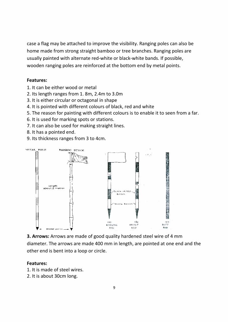
case a flag may be attached to improve the visibility. Ranging poles can also be
home made from strong straight bamboo or tree branches. Ranging poles are
usually painted with alternate red-white or black-white bands. If possible,
wooden ranging poles are reinforced at the bottom end by metal points.
Features:
1. It can be either wood or metal
2. Its length ranges from 1. 8m, 2.4m to 3.0m
3. It is either circular or octagonal in shape
4. It is pointed with different colours of black, red and white
5. The reason for painting with different colours is to enable it to seen from a far.
6. It is used for marking spots or stations.
7. It can also be used for making straight lines.
8. It has a pointed end.
9. Its thickness ranges from 3 to 4cm.
3. Arrows: Arrows are made of good quality hardened steel wire of 4 mm
diameter. The arrows are made 400 mm in length, are pointed at one end and the
other end is bent into a loop or circle.
Features:
1. It is made of steel wires.
2. It is about 30cm long.

10
3. One end of the pin is curved into a ring.
4. During usage, a red cloth is tied to the ring end.
5. The red cloth enables the pin to be seen from afar.
6. It is used for marking off chain lengths as measured.
7. It can also be use for marking spots or stations.
8. It has a thin pointed end.
4. Chain: A chain is used to measure distance on the field. The chain is composed
of 100 or 150 pieces of connected galvanized mild steel segments, 4mm in
diameter and 20cm called links. The ends of each link are bent into a loop and
connected together by means of three oval rings. The ends of the chain are
provided with handles for dragging the chain on the ground, each wire with a
swivel joint so that the chain can be turned without twisting.
Usually, a chain has a total length of 20 meters, including one handle at each end.
The length of the chain is measured from the outside of one handle to the outside
of another handle.
Types of chains:
The following are the various types of chains used in surveying:
1) Metric chain
2) Gunter`s chain or surveyors chain
3) Engineers chain
4) Revenue chain
5) Steel band or Band chain

11
Features of a Metric chain:
1. Metric chains are made in lengths 20m and 30m.
2. Tallies are fixed at every five-meter length and brass rings are provided at every
meter length except where tallies are attached.
Features of a Gunter’s chain:
1. This is surveyor’s chain that was used before tapes were discovered.
2. It is made of steel wires which are dumb-bell in shape.
3. Each chain is joined together by links of three small rings.
4. A Gunter’s chain is about 66ft or 20. 13m in length.
5. Each chain is made of about 100 links and each link is about 19.8cm or 7.92
inches.
6. It is used in taking detailed measurement of the length and breadth of land.
7. The handle at each end is made of brass.
8. A link is the distance between two central rings.
9. It is majorly used in taking short or detailed measurement of length and
breadth.
12
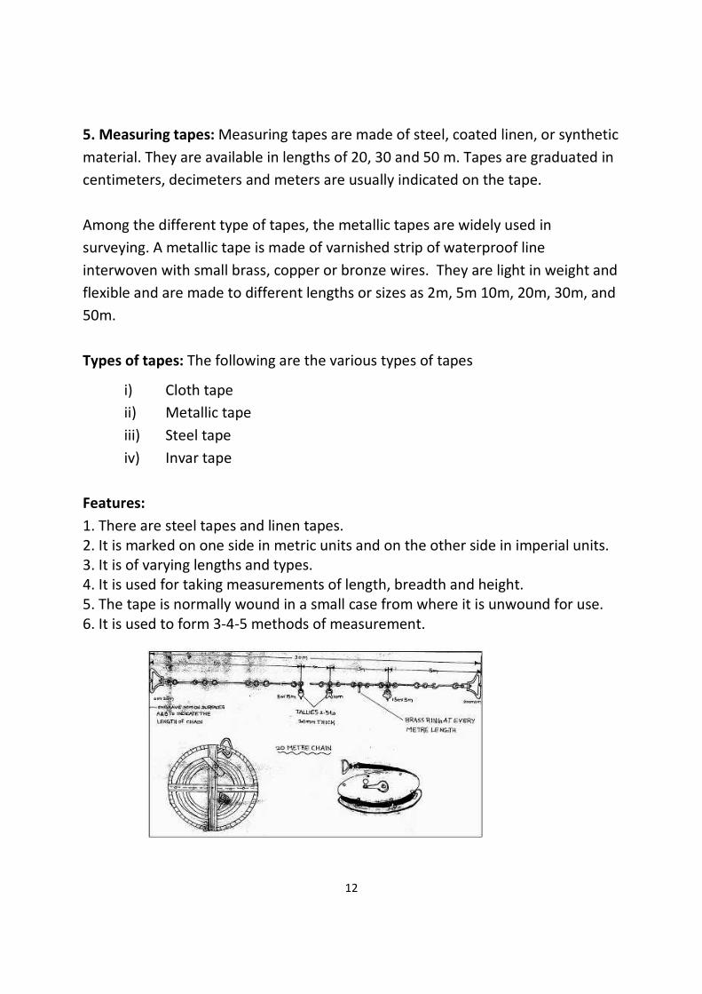
5. Measuring tapes: Measuring tapes are made of steel, coated linen, or synthetic
material. They are available in lengths of 20, 30 and 50 m. Tapes are graduated in
centimeters, decimeters and meters are usually indicated on the tape.
Among the different type of tapes, the metallic tapes are widely used in
surveying. A metallic tape is made of varnished strip of waterproof line
interwoven with small brass, copper or bronze wires. They are light in weight and
flexible and are made to different lengths or sizes as 2m, 5m 10m, 20m, 30m, and
50m.
Types of tapes: The following are the various types of tapes
i) Cloth tape
ii) Metallic tape
iii) Steel tape
iv) Invar tape
Features:
1. There are steel tapes and linen tapes.
2. It is marked on one side in metric units and on the other side in imperial units.
3. It is of varying lengths and types.
4. It is used for taking measurements of length, breadth and height.
5. The tape is normally wound in a small case from where it is unwound for use.
6. It is used to form 3-4-5 methods of measurement.

13
6. Pegs: Pegs are used when certain points on the field require more permanent
marking. Pegs are generally made of wood; sometimes pieces of tree-branches,
properly sharpened, are good enough. The size of the pegs depends on the type
of survey work they are used for and the type of soil they have to be driven in.
The pegs should be driven vertically into the soil and the top should be clearly
visible.
7. Cross staff:
This is the simplest instrument used for setting out a right angle. The common
forms of cross staff are:
• Open cross staff
• French cross staff

14
8. Offset rod:
The offset rod is used for measuring the off set of short lengths. It is similar to a
ranging rod and is usually of 3m lengths.
Features:
1. It is a graduated rod.
2. It is about 3m long.
3. A hook may be attached to the top, which helps in the pulling of chains through
hedges.
4. It is used for taking short off-set measurements.
5. There is a telescopic link which is 0.3m (30cm) in length.
9. Theodolite:
A theodolite is a precision instrument for measuring angles in the horizontal and
vertical planes. A modern theodolite consists of a movable telescope mounted
within two perpendicular axes—the horizontal or trunnion axis, and the vertical
axis. When the telescope is pointed at a desired object, the angle of each of these
axes can be measured with great precision, typically on the scale of arcseconds.
Types of theodolite
1. Transit and non-transit theodolite
2. Vernier and Micrometer Theodolite
3. Electronic Theodolite
4. Optical Theodolite

15
10. Dumpy Level:
A dumpy level is an instrument used to measure, transfer or set horizontal lines.
It is an instrument that is often used in surveying buildings. A dumpy level is used
to establish relative height, distance and bearings from different parts of a site.
Using this instrument requires a certain amount of skill.
Uses of Dumpy Level
• Determining the height of a particular point.
• Determining differences in height between points.
• Drawing contours on a land.
• Providing data to calculate volumes for earthworks.
• Setting out level surfaces for construction.
• Setting out inclined surfaces for construction.
Setting up the dumpy
• Choose a position for the dumpy with a good
sightline to the datum and also to as much of
the ground to be surveyed as possible. Further
up the slope is more useful than too low down
on the slope. Use the full height of the staff
where possible.
• Set up the tripod – it has adjustable feet to
allow it to be upright on uneven ground. Ensure
the tripod is secure, its feet pressed into the
ground if possible. Do not disturb the tripod until it is time to move it again.
• Attach the dumpy to the tripod.
• Level the dumpy using the spirit level – the bubble must be centered in its
circle. Turn 2 of the adjustable screws towards or away from each other until
the bubble is near the centre. Turn the dumpy 90° towards the untouched
screw and adjust this till the bubble is centered.

16
STUDY OF THEODOLITE
Aim: To Study different components of Theodolite
Apparatus: Theodolite
Theory: The theodolite is an instrument designed for the measurement of
horizontal and vertical angles. Theodolite is the most precise instrument; it is also
used for laying off horizontal angles, locating points on the line, prolonging the
survey lines, establishing grades, determination of difference of elevation setting
out curves, observation of bearings etc.
Types of theodolite:
The theodolites may be primarily of two types:
• Transit Theodolite
• Non Transit Theodolite
In a transit theodolite the telescope can be revolved through a complete
revolution about its horizontal axis in a vertical plane.
In non transit theodolite, the telescope is mounted in such a manner that the line
of sight cannot be reversed by revolving the telescope.
COMPONENTS PARTS OF A THEODOLITE:
Leveling head: It supports the main working parts of the instrument and screw on
the tripod. The head comprises of two parts:
• Leveling base or tribrach fitted with leveling foot screws for leveling the
instrument.
• Movable head or centering arrangement for centering the vertical axis
accurately over the station.
Lower circular horizontal metal plate: It carries a circular graduated arc. It is
silvered and graduated from 00 to 3600 in a clock wise direction.
Upper circular horizontal metal plate: The upper plate carries an index and
vernier to Read fine reading on the graduated horizontal circle.
17
Telescope: Fitted to a horizontal axis, it consists of eye piece and diaphragm at
one end and objective glass at the other end. The telescope has focusing screw by
which any Object can be bisected.
Circular graduated arc on a vertical circle: It is attached to the horizontal axis of
the telescope. It is usually divided into 4 quadrants, but in some instruments it is
graduated from 00 to 3600 the sub divisions of the vertical circle are similar to
those of horizontal circle.
Vernier frame: carrying an index and verniers to measure vertical angles.
Lower clamp and lower tangent screw: A lower clamp, clamps the lower plate
and the lower tangent screw enables finely controlled circular motion of lower
plate.
Upper clamp and upper tangent screw: An upper clamp, clamps the upper plate
to lower one, and the upper tangent screw enables finely controlled circular
motion about vertical axis.
Vertical circle clamp and tangent screw: A vertical circle clamp, clamps the
vertical circle and its tangent screw enables a finely controlled circular movement
to be given to the combined telescope and vertical circle about the horizontal
axis.
Circular level: It is located on the top of tribrach.
Plate level: It consist of plate bubble, which keeps the instrument parallel to
horizontal axis.
Compass: A circular or trough compass may be mounted on the vernier plate
between the standards for observing bearings.
Tripod: Theodolite is mounted and fixed on the tripod for each set up. As tripod
has adjustable legs, theodolite can roughly leveled with the adjusting the legs of
tripod.
18
STUDY OF PLANIMETER
Aim: To Study Planimeter and to find constants of the Planimeter.
Apparatus: Planimeter
Theory: A Planimeter is used by engineers for measuring area of any figure which
has been plotted to scale particularly when the boundaries are irregular or
curved. Planimeter is largely used for finding the area of contours in determining
the capacity of storage reservoirs.
CONSTRUCTION OF PLANIMETER:
• The Planimeter consists of two arms, the tracing arm and anchor arm.
The tracing arm is of adjustable length and has a tracing point which is
moved round the periphery of the area to be measured.
• The amount by which tracing arm is moved is known on the wheel or
roller which has its axis parallel to the tracing arm. The wheel has a
roller divided into 100 equal parts and 1/100th of drum division is read
from the vernier having graduations from 0 to 9. The complete
revolution of the wheel is recorded from 0 to 9. While taking the
reading on the planimeter, the reading will be in 4 digits. Let the
reading be 4.375
• The 1st digit (4) is read on the disc.
• The second digit (3) is read on the rolling wheel (main scale).
• The third digit (7) is read on the rolling wheel (main scale).
• And the last digit (5) is read on the vernier scale besides the main scale
of rolling wheel.

19
• Setting of tracing arm: The setting arm has calibrations on it and which
facilitates the setting of tracing arm to given scale of the plan or map.
• The adjustment which is to be made on the tracing arm as per scale of
figure is given by the manufacturer. The multiplying and additive
constants are also provided by manufacturer.
• While rotating the tracing arm round the periphery of the plan, the
anchor point may be kept inside or outside the plan depending on the
size of the figure. For large area the anchor arm is kept inside the figure
for small area the anchor arm is placed outside the area.
Procedure:
• Make the adjustments of the tracing arm as per scale of the plan.
• The anchor is placed inside or outside of figure such that the tracing
point can be conveniently moved on the periphery of the plan.
• Any point on the periphery of the plan can be taken as the starting
point and from where the tracing point moves along the periphery and
closes back.
• Before the start of tracing work the initial reading (I.R) is recorded and
the final reading (F.R) at the end of tracing is noted down.
• While moving the tracing point around the periphery it is necessary to
note down the number of times the zero of the counting disc has
passed the fixed index mark in clock wise (+ve) and anticlockwise (-ve)
directions.
• Compute the area by using the formula:
A=M (F.R – I.R ±10 N +C)

20
Where,
A= Area of the plan to be computed.
M=Multiplying constant.
F.R= Final reading on the disc.
I.R=Initial reading on the disc.
N= No of times the zero mark of the dial or disc crosses the fixed index
mark .Positive sign should be used if in clockwise and negative sign if it
crosses in anticlockwise direction.
C= Constant to be added if the anchor point is inside the plan of figure.
C=0, if the anchor point is outside the figure.
OBSERVATION TABLE
WHEN ANCHOR POINT IS OUTSIDE THE
FIGURE
WHEN ANCHOR POINT IS INSIDE THE
FIGURE
S.NO. I.R. F.R. N M S.NO. I.R. F.R. N M
CALCULATIONS AND RESULTS
CONCLUSION

21
ANGULAR MEASUREMENT
Aims:
• Understand that theodolites and total stations measure horizontal and
vertical angles.
• Assess the accuracy of a theodolites and total station for site work.
• Describe all the components of a theodolites and explain how these are
used when measuring and setting out angles.
• Outline the differences between electronic and optical theodolites.
• Describe the field procedures that are used to set up and measure angles
with a theodolites or total station.
• Book and calculate horizontal and vertical angles from theodolites readings.
• Understand the sources of error in using a theodolites and how to control
these.
Theory:
Definition of horizontal and vertical angles:
Horizontal angles are used to determine bearings and directions in control
surveys, for locating detail when mapping and for setting out all types of
structure. Horizontal angle is the difference between two intersecting lines when
they are projected onto the datum plane.
Vertical angles are used when determining the heights of points and to calculate
slope corrections. Vertical angle is the angle of elevation or depression between
the line of collimation and the horizontal plane which passes through the
horizontal axis of the theodolite.
To measure horizontal and vertical angles, a theodolite or a total station is used.

22
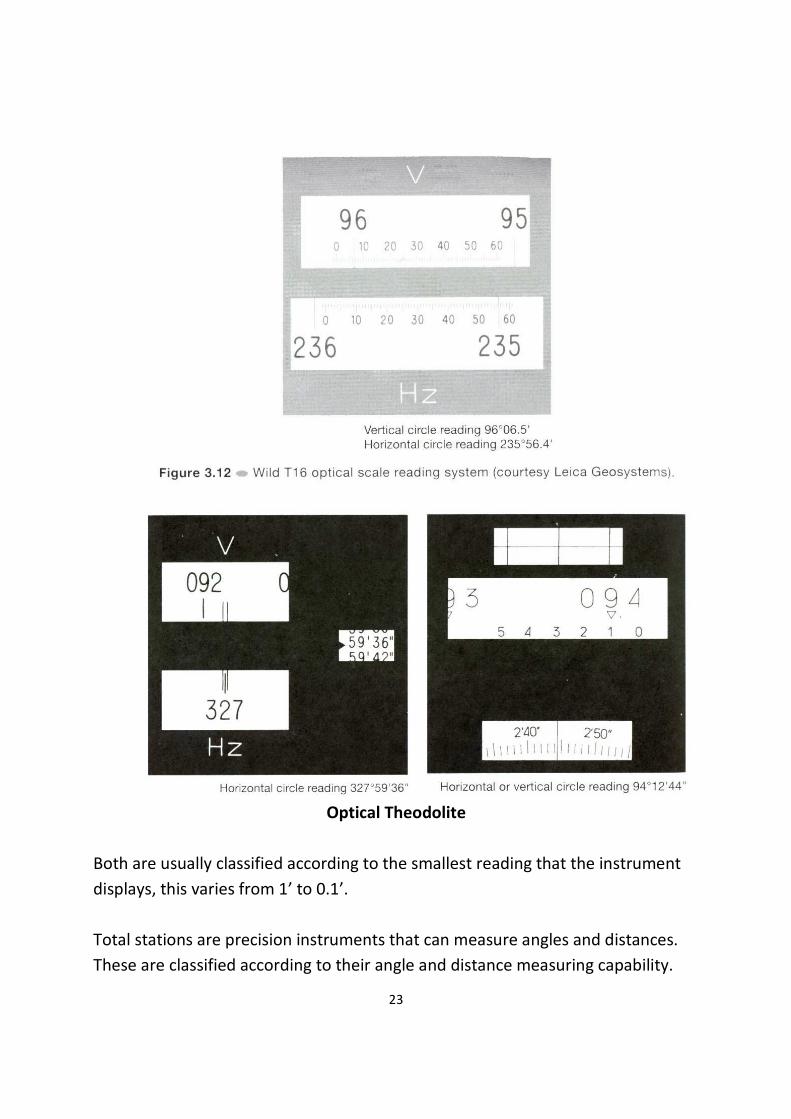
Theodolites are precision instruments used for measuring both vertical and
horizontal angles. Two examples of theodolites are: electronic theodolites (which
read and display angles automatically) and Optical theodolites (which read and
display angles manually).
Electronic theodolite
23
Optical Theodolite
Both are usually classified according to the smallest reading that the instrument
displays, this varies from 1’ to 0.1’.
Total stations are precision instruments that can measure angles and distances.
These are classified according to their angle and distance measuring capability.

24
Errors in angular measurement
1. Instrumental errors
2. Human errors
3. Natural errors
Instrumental Errors:
• Also called systematic errors, can be corrected through permanent
adjustment of the theodolite.
• 5 types: Vertical axis error; Horizontal axis error; Horizontal collimation
error; Vertical collimation error; Optical plummet error.
Natural Errors:
• Smaller in magnitude and in a random pattern.
• They are:
1. Unequal atmospheric refraction (choose cool days or night time);
2. Differential expansion in certain of the theodolite (insulation);
3. Vibration of the theodolite due to strong wind
4. Improper settlement of the tripod (pushing tripod legs firmly into the
grounds)
5. Limitations of the theodolite reading systems and human eyesight
6. Heat shimmer
(Note: minimize time spent on the observations and movements around
the theodolite).
Human Errors:
• These are mistakes caused by poor observational techniques or
carelessness.
• They are serious and significant as it is impossible to correct or make
adjustments.

25
• They can be avoided if proper field procedure is adopted such as observing
more than one round of observations.
These errors include:
1. Setting up the theodolite on a wrong station.
2. Sighting a wrong target.
3. Failing to recognize the settlement of the tripod.
4. Transcribing errors and interchanging digit in booking.
5. Reading the wrong circle in the reading system.
6. Ignoring the movement of the plate bubble during observation.
7. Failing to adjust the eyepiece to eliminate parallax completely.
Sources of Errors:
1. Errors in the equipment: Plate level not in adjustment
The purpose of levelling a theodolite or total station is to make its vertical axis
coincide with the vertical through the instrument. If the plate level is not in
adjustment, it is possible that when the instrument appears to be level and the
plate level bubble centered, the vertical axis may be tilted.
26
If the instrument is not level, it is not possible to remove any errors caused by this
when observing and setting angles on both faces.
If the theodolite is levelled electronically, it will usually be fitted with a dual-axis
compensator and it can calculate corrections for any errors caused by vertical axis
tilt and will apply these to displayed horizontal and vertical angles.
However, the compensator itself may be out of adjustment. To correct for this,
an on-board electronic calibration can be carried out in which the compensator
index errors are measured and then automatically applied to all readings.
It can be shown that the error in horizontal angles caused by the theodolite not
being level is proportional to the tangent of the vertical angle of the line of sight.
Consequently, it is important to ensure that the theodolite is carefully levelled for
any steep sightings such as those taken to tall buildings and into deep excavations
when on site.
2. Errors in the equipment: Horizontal collimation error
This error occurs when the line of sight is not perpendicular to the tilting axis -
this detected by taking face left and face right horizontal circle readings to the
same point – if these do not differ by exactly 180˚, the theodolite has a horizontal
collimation error.
The error is removed by taking the average of face left and face right readings to
any given point and by taking the mid-point when setting out angles on both
faces. It can also be removed in an electronic calibration.
3. Errors in the equipment: Tilting Axis not horizontal
If the tilting axis of the theodolite is not perpendicular to the vertical axis, it will
not be horizontal when the theodolite has been levelled. Since the telescope
rotates about the tilting axis it will not move in a vertical plane which will give rise
to errors in measured horizontal angles.

27
As with the horizontal collimation error, this error is also removed by taking the
average of face left and face right readings, by setting out on two faces or by
carrying out an electronic calibration on the instrument.
4. Errors in the equipment: Vertical Collimation error
When a theodolite is levelled, it is assumed that the automatic vertical circle index
sets the vertical circle to read 90˚ when horizontal on face left and 270˚ when
horizontal on face right. To detect this error, the same point is sighted on face left
and face right and a vertical circle reading taken – when added these should be
exactly 360˚ or a vertical collimation error is present in the theodolite.
The vertical collimation error is cancelled by taking the mean of face left and face
right readings. To remove this error, an electronic calibration can be carried out.
5. Errors in the equipment: Plummet error
The line of collimation of an optical or laser plummet must coincide with the
vertical axis of the theodolite. Tests should be carried out on site to check this.
6. Errors in the equipment: Tripods and Tribach
The clamping mechanism and circular bubbles of tribrachs should be checked
regularly. All of the parts of a tripod should also be inspected regularly to check
that they have not become loose.
7. Field or on site errors: Instrument not levelled properly
Failure to level a theodolite properly will cause the vertical axis to be tilted
If the instrument has been poorly levelled, errors will occur in measured angles
that are not eliminated by observing on face left and face right.
Although instruments fitted with dual-axis compensators can correct for the
effects of a tilted vertical axis, it is still good practice to take some care when
levelling theodolite that have a compensator.

28
If a theodolite is found to be off level whilst measuring or setting out an angle, it
is best to re-level the instrument and repeat the measurements.
8. Field or on site errors: Mis-centering
If a theodolite is not centered exactly over a point incorrect horizontal angles will
be measured. This error increases as the line of sight gets shorter, consequently,
great care must be taken with centering when sighting over the short distances
that are often used on site and in engineering surveying.
The same errors can occur if a tripod mounted target is not centered properly and
when a detail pole is either mis-centered or is not held vertical.
9. Field or on site errors: not using theodolite properly
• Make sure parallax is removed
• Change the focus for each target sighted
• Use the tangent (slow motion) screws to intersect targets
• Don’t lean on the tripod
10. Field or on site errors: ground and weather conditions
• Avoid setting the instrument up on soft ground
• When working in hot sunshine shade the instrument
• Do not take measurements when refraction is a problem
• Let the instrument adjust to atmospheric conditions
Observing and setting out angles in windy conditions is not recommended
MEASURING ANGLES AND SETTING OUT ANGLES
Setting up a theodolite
This is carried out in three stages: Centering the theodolite; Levelling the
theodolite; Removal of parallax.

29
The following procedure is recommended where it is assumed that the theodolite
is to be centered over a nail in the top of a peg. This is a typical point or reference
mark used in construction and setting out.
a. Leaving the instrument in its case, the tripod is first set up over the peg.
The legs of the tripod are placed an equal distance from the peg and are
extended to suit the height of the observer.
b. The tripod head should be made as level as possible by eye. Standing back a
few paces from the tripod, the centre of the tripod head is checked to see if
it is vertically above the peg – this should be done by eye from two
directions at right angles.
c. If the tripod is not centered, each leg is moved a distance equal to the
amount the tripod is judged to be off centre and in the same direction in
which it is not centered. It is important to keep the tripod head level when
changing its position.
d. When the tripod has been centered in this way, the tripod legs are pushed
firmly into the ground.
e. If one foot goes in more than the others making the tripod head go off
level, this can be allowed for by loosening the clamp of the tripod leg
affected, adjusting the length and then re-clamping.
f. The theodolite is carefully taken out of its case, its exact position being
noted to help in replacement, and it is securely attached to the tripod head.
Whenever carrying a theodolite, always hold it by the standards and not
the telescope. Never let go of the theodolite until it is firmly screwed onto
the tripod.
g. The ground mark under the theodolite is now observed through the optical
plummet. The plummet is adjusted such that the nail in the peg and the
plummet’s reference mark are seen together in clear focus.
h. By adjusting the three foot screws, the image of the nail seen through the
plummet is moved until it coincides with the reference mark. If the
instrument is fitted with a laser plummet, the foot screws are adjusted so
that the beam is centered on the ground mark (nail).

30
i. The circular bubble on the tribrach is now centered by adjusting the length
of individual tripod legs, as required.
j. At this stage, the theodolite is almost centered and is almost level. To level
the instrument exactly, the plate level is used.
k. The procedure for this is as follows and is the only one recommended for a
three-foot screw instrument. To level a theodolite it is rotated until the
plate level axis is parallel to the line through any two foot screws as shown
l. These two foot screws are turned until the plate bubble is brought to the
centre of its run. The levelling foot screws should be turned in opposite
directions simultaneously, remembering that the bubble will move in a
direction corresponding to the movement of the thumb. The instrument is
turned 90°and the bubble centered again but using the third foot screw
only.

31
m. This process is repeated in both positions until the plate level bubble is
central in both positions. The instrument is now turned until the plate is in
a position 180°from the first. If the plate level bubble is still in the centre of
its run, the theodolite is level and no further adjustment is needed.
n. If the bubble is not centered, it has an error equal to half the amount the
bubble has run off centre. If, for example, the bubble moves off centre by
two plate level divisions to the left, the error in the bubble is one to the
left. If the plate level has an error, the theodolite is returned to its original
position and the plate level bubble is moved off centre an amount equal to
the error in the bubble.
o. This is done using the two foot screws in line with the axis of the level.
Using the example already quoted, the bubble would be placed one division
to the left. The instrument is then turned 90°and the plate level bubble is
again moved off centre an amount equal to the error in the bubble but
using the third foot screw. Once again, the bubble would be placed one
division to the left.
p. The instrument is now slowly rotated through 360°and the plate level
bubble should remain in the same position throughout (one division to the
left in this case).
32
q. The theodolite has now been levelled and the vertical axis with the vertical
through the instrument.
r. When the theodolite has been levelled and centered, parallax is eliminated
by accurately focusing the cross hairs of the telescope against a light
background and focusing the instrument on a distant target.
s. At this stage the theodolite is ready for reading angles or for setting out. If
any point is occupied for a long time, it is necessary to check the levelling
and centering at frequent intervals, especially when working on soft ground
or in hot sunshine.
t. All of the procedures given in this section for setting up a theodolite are
also used when centering and levelling a total station. They are also used
for setting up a tripod-mounted GPS antenna or laser scanner over a
control point.
Measuring angles:
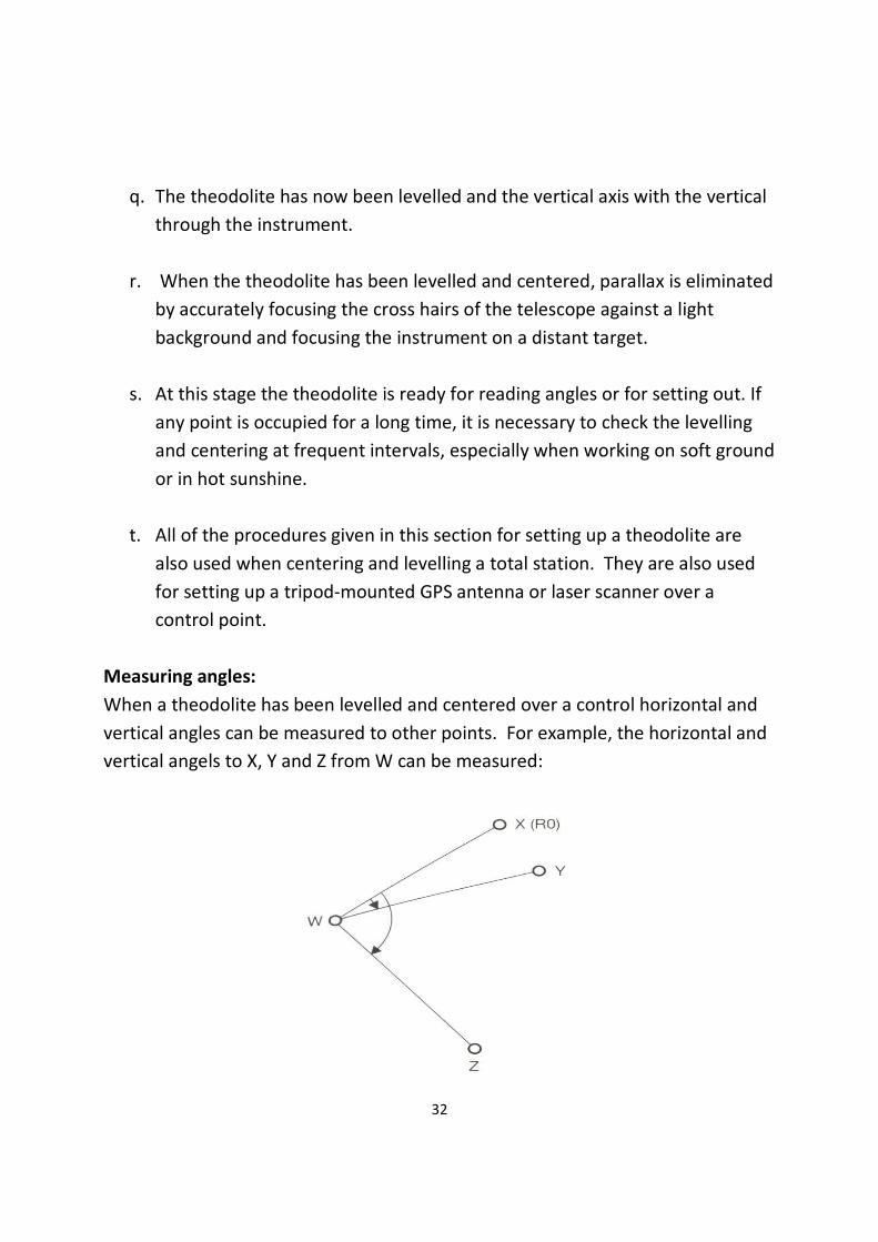
When a theodolite has been levelled and centered over a control horizontal and
vertical angles can be measured to other points. For example, the horizontal and
vertical angels to X, Y and Z from W can be measured:

33
In order to be able to measure angles to these it may be necessary to establish
targets at X, Y and Z. Targets can be tripod mounted, pole mounted or hand held.

34
Booking Angles:
1. Starting with the horizontal angles at W, one point is chosen as the reference
object (RO). Point X is chosen and angles are referred to this point i.e. the angles
XWY and XWZ.
2. To begin, a reading is set along the RO direction in the Face Left Position, and is
recorded in the Face Left (FL) column (the theodolite can be zeroed in this
position is required).
3. Points Y and Z are then sighted and FL readings of 17°22’10’’ and 83°58’50’’ are
recorded. The telescope is transited so that the theodolite is now in the face right
position and the horizontal angles are recorded again in reverse order Z, Y and X.
4. At this stage one set of angles has been completed. The theodolite is changed
back to face left and sighted at Point X. The horizontal circle is set to a different
reading from the first reading of X 45°12’30’’ in this case, such that the degrees
minutes and seconds are different.
5. The process is repeated as before with FL and FR readings are taken.
Repeating this process is carried out to detect and minimize errors in the survey.
Note: the procedure for measuring the vertical or zenith angles is similar to that
for the horizontal angles except that the vertical circle is used in this case.
Reducing angles:
1. The face left and face right measurements are first averaged to obtain the
mean horizontal readings. To simplify these calculations the degrees of the face
left readings are carried through and only the minutes and seconds are averaged.
2. The horizontal angles are then reduced to the RO by subtracting its reading.
The final horizontal readings are obtained by taking the average of the two
rounds.

35
3. In this case, for the vertical readings the vertical circle was set at 0°at the zenith
angle. When reducing zenith angles it is usual to convert them to vertical angles
as follows:
FL vertical angle = 90°- zenith angle
FR vertical angle = FR zenith angle - 270°
On the booking form these are computed by:
Reduced face left = 90°- face left
Reduced face right = Face right – 270°
Each final vertical angle is then obtained by average the reduced FL and FR values.
Final check for errors are carried following these calculations, firstly each FL and
FR reading should differ by 180°. Secondly, considering minutes and seconds only
the difference (FL – FR) is computed, e.g. for the first round of horizontal
readings.
Station (FL-FR)
X -00’40’’
Y -01’00’’
Z -01’10’’
Assuming a 10’’ theodolite was used this is satisfactory as the reading taken
should agree to within 30’’ for each point.
For the vertical circle readings the FR and FL values should sum to 360°. In this
example:
Station (FL + FR)
X 88°10’30’’ + 270°51’20’’ = 360°01’50’’
Y 360°02’20’’
Z 360°02’00’’

36
All of these values agree very closely and therefore the readings are consistent
and acceptable.
All the procedures given above for measuring angles are also used with to
measure angles with a total station.
Setting out angles:
Line extensions
For some types of construction work, it is often necessary to prolong a straight
line AB.
The theodolite is set up at B and point A is sighted on face left. Keeping the
horizontal clamp locked, the telescope is transited to face right and because the
instrument is likely to have a horizontal collimation error, point C’ is established
on the line of sight instead of C.
The horizontal clamp is now released, the instrument is rotated and A sighted
once again. When the telescope is transited back to face left, point C’’ is
established next to C’. Point C is midway between C’ and C’’.
Grids or intermediate points
To set out intermediate points in between two fixed points A and B, a theodolite
is set up at A, B is sighted on either face and all intervening points can then
established directly on the line sight of the telescope. A good example of this on
site occurs when establishing column or other positions on such a grid. In this
case, two theodolite positions are fixed at the intersection of these two lines.

37
COMPASS SURVEY
STUDY OF COMPASS USED IN COMPASS SURVEYING
Aim: To study the different types of compass used in compass surveying.
Instrument:
• Compass
Theory:
What is compass survey?
Compass survey is a method of surveying by taking bearings and linear distances
to produce plan. Bearing is measured using prismatic compass, while the linear
distance is measured using measuring tape.
Compass surveying is recommended for use to survey a large area to include:
• The course of a river (or) coast line.
• An area crowded with many details and triangulation is not possible
Definition of a few compass terms:
1. MERIDIAN – it is the fixed direction in which the bearings of survey lines are
expressed
2. BEARING – it is horizontal angle between the reference meridian and the
survey line measured in clockwise or anticlockwise direction
3. TRUE MERIDIAN – The true meridian passing through a point on the earth
surface is the line in which a plane passing through and the north and south
poles, intersects the surface of the earth.
4. TRUE BEARING – The horizontal angle measured clockwise between the
true meridian and the line is called true bearing of the line.
5. MAGNETIC MERIDIAN – the direction indicated by a freely suspended and
balanced magnetic needle unaffected by local attractive forces
6. MAGNETIC BEARING – The horizontal angle which a line makes with the
magnetic meridian.
SOURCES OF ERROR IN COMPASS WORK
• Instrumental errors

38
• Observational or personal errors
• Errors due to External Influences (natural causes)
Instrumental Errors:
They are those which rise due to the faulty adjustments of the instruments. They
may be due to the following reasons:
• The needle not being perfectly straight.
• Pivot being bent
• Sluggish needle
• Blunt pivot point
• Improper balancing weight
• Plane of sight not being vertical
• Line of sight not passing through the center of graduated ring
Observational or Personal Errors:
They may be due to the following reasons:
•Inaccurate leveling of the compass box.
• Inaccurate centering.
• Inaccurate bisection of signals.
• Carelessness in reading and recording.
Natural Errors:
They may be due to following reasons:
• Variation in declination
• Local attraction due to proximity of local attraction forces.
• Magnetic changes in the atmosphere due to clouds and storms.
• Irregular variations due to magnetic storms etc. TYPES OF COMPASS:
There are two types of compass, namely:
1. Prismatic Compass (0 to 360 Degrees)
2. Surveyor’s Compass (0 to 90 Degrees)
The working of a Prismatic compass involves the following three steps: centering,
leveling and observation of bearing.

39
Fore Bearing and Back Bearing: The bearing of the line in the direction of
progress of the survey is called Fore-Bearing (FB), while the bearing in the
opposite direction is called Back Bearing (BB). Therefore BB of a line differs from
FB by exactly 180o.
Designations of bearings
Bearings are expressed in the following ways;
• Whole circle bearing: In this system, the bearing of a line is measured with
the magnetic north in clockwise direction. The value of bearing thus varies
from 0o to 360
o.
• Quadrant bearing: In this system, the bearing of a line is measured
eastward or westward from north or south whichever is near. The
directions can be either clock wise or anti clockwise depending upon the
position of the line. It will have value up to 90o.
DIFFERENCE BETWEEN THE PRISMATIC COMPASS AND THE SURVEYOR'S
COMPASS.
1. Prismatic Compass
1. The sighting of an object and reading of the bearing are done
simultaneously
2. This can be used without stand
3. The graduated ring is attached to the magnetic needle
4. Graduation are marked 0o and 360
o in clockwise direction
5. 0o is marked at south, 180o at north, 90o at west and 270o is marked
at east.
6. It measures or gives the whole circle bearing of a line.
2. Surveyor’s Compass
1. An object is sighted first and the bearing is then read by going
vertically over the middle point
2. This cannot be used without a stand
3. The graduated ring and needle are free to move with respect to each
other
4. Graduation are marked 0o to 90o in each quadrant
5. In this compass, east and west are interchanged

40
6. It measures or gives the quadrant bearing of a line
DESCRIPTION OF THE PARTS OF A COMPASS
1. Compass Box 2. Magnetic Needle
3. Graduated Ring 4. Pivot
5. Objective Vane 6. Eye Vane
7. Adjustable Mirror 8. Spring Brake
9. Brake Pin 10. Lifting Lever
11. Lifting Pin 12. Prism
13. Focusing Stud 14. Glass Cover
15. Prism Dust Cap 16. Sun Glasses
COMPASS BOX:
It is a circular box of diameter 85 to 110 mm having pivot at the center and
covered with plain glass at top.
MAGNETIC NEEDLE:
It facilitates in taking the bearings of survey lines with reference to the magnetic
north.

41
GRADUATED RING:
The bearings are marked inverted on the graduated Rings from 0° to 360° in a
clock-wise starting 0° from south.
PIVOT:
Magnet is freely held with this.
OBJECT VANE:
It consists of prism with a sighting slit at the top. The prism magnifies and erects
the inverted graduations.
BRAKE PIN:
It is pressed to stop the oscillations of the graduated ring.
LIFTING PIN:
On pressing it brings the lifting lever into action.
COLOUR GLASSES:
Red and blue glasses are provided with the prism to sight luminous objects
42
PRISMATIC COMPASS
Aim:
- To study the prismatic compass and
- To determine,
• Fore and back bearing of line AB, BC, CA.
• The included angles.
Apparatus: Tripod, prismatic compass, ranging rods, measuring tapes, wooden
pegs, hammer.
Theory:
Fore Bearing: The bearing of a line measured in the direction of progress of
survey is called Fore-Bearing.
Back Bearing: The bearing of a line measured in the opposite direction of progress
of survey is called Fore-Bearing.
Parts of a prismatic compass
Compass Box:
1. Circular 8 to 10 cm (80mm to 100mm) metallic
2. At the center of box pivot is provided.
Magnetic Needle and Graduated Ring:
1. On pivot the magnetic needle rests
2. Aluminum graduated ring is attached to needle
3. Graduated ring has 0 degree to 360 degrees clockwise
4. i.e. 00 at south, 900 at west, 1800 at north, 2700 at east
5. Least count is 30minutes

43
Sight Vane and Object Vane Of Compass:
• These are fixed diametrically opposite to the each other.
• Object vane consists of vertical hair attached to the frame
• Sight vane (or eye slit) consists of vertical slit cut into upper assembly of the
prism unit. Prism unit is hinged to the box
• Adjustments of Prismatic Compass
• Fixing the compass with tripod stand.
• Centering
• Leveling
• Adjustment of prism
• Observation of bearing
• Bearings are designated by two systems
• Whole Circle Bearing (WCB )
• Quadrantal Bearing or Reduced bearings( QB / RB )
• Whole circle bearing (W.C.B.)
• The bearing of a line measured from the north in clockwise direction.
• The value of WCB may vary from 00 to 3600

44

45
PROCEDURE:
TEMPORARY ADJUSTMENTS OF A PRISMATIC COMPASS
The Prismatic Compass is set up at a point say station A.
The following temporary adjustments are needed to be carried out at each set up
of Instrument.
• Centering: Centering is the process of keeping the instrument exactly over
the station. It is carried out by dropping a piece of stone so that it falls on
the top of the pegs fixed at station point.
• Leveling: Prismatic compass is leveled by means of ball and socket
arrangement so that the graduated ring may swing freely.
• Focusing the prism: The reflecting prism is adjusted to the eye sight of the
observer by raising or lowering then stud until the graduations are seen
sharp and clear.
CALCULATION OF FORE AND BACK BEARING
• Suppose the bearing of line AB, BC, CA of a triangle is to be observed. Set
up the instrument at station A and carry out all the temporary adjustments.
Fix the ranging rod at B.
• Turn the prismatic compass until the ranging rod at station B is bisected by
the horse hair when seen through the vertical slit above the prism.
• When the needle comes to rest bisect ranging rod at B exactly and note the
reading. The reading observed is the Fore bearing of line AB i.e. Angle
measured with respect to north.
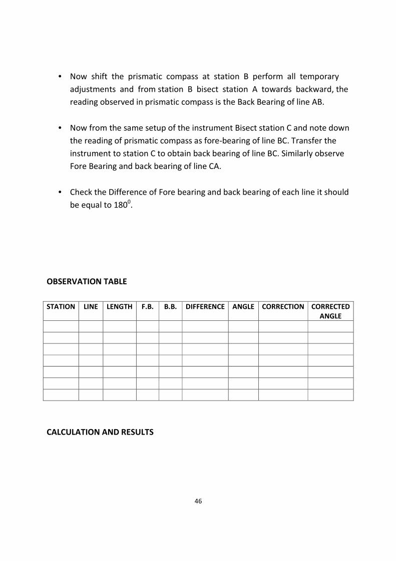
46
• Now shift the prismatic compass at station B perform all temporary
adjustments and from station B bisect station A towards backward, the
reading observed in prismatic compass is the Back Bearing of line AB.
• Now from the same setup of the instrument Bisect station C and note down
the reading of prismatic compass as fore-bearing of line BC. Transfer the
instrument to station C to obtain back bearing of line BC. Similarly observe
Fore Bearing and back bearing of line CA.
• Check the Difference of Fore bearing and back bearing of each line it should
be equal to 1800.
OBSERVATION TABLE
STATION LINE LENGTH F.B. B.B. DIFFERENCE ANGLE CORRECTION CORRECTED
ANGLE
CALCULATION AND RESULTS

47
TO FIND INCLUDED ANGLES
• Included Angles of a triangle are calculated from observed FB and BB of line
AB, BC, CA.
• Included angle is determined by following formula.
• ∠= Back Bearing of Previous Line- Fore Bearing of next line i.e. for triangle
ABC
∠ A= BB of CA – FB of AB
∠ B=BB of AB – FB of BC
∠C=BB of BC – FB of CA
• Check: Sum of all included angles Should be Equal to (2n-4) x 900
CONCLUSION

48
THEODOLITE TRANSVERSING
DIRECT ANGLE, DEFLECTION ANGLE AND MAGNETIC BEARING OF A LINE
Aim: To measure direct angle, deflection angle and magnetic bearing of a line by
using theodolite.
Apparatus: Transit thedolite, ranging rod, pegs etc.
(1) Measurement of Direct Angle:
The angle measured clockwise from preceding line to the following line. They
may vary 0° to 360°.
Procedure:
- Set up the thedolite at O and level it accurately set vernier A to 0°0΄0˝.Loose the
lower plate and take back sight on A.
- Loose upper plate rotate telescope clockwise and bisect B exactly read both
vernier. Plunge the telescope turns the instrument about its outer axis and take
back sight on A the reading on vernier A will be same as in Step 1.
- Loose the upper plate, turn the telescope clockwise and again bisect B exactly.
- Read both verniers. The reading will be twice the previous, <AOB will be obtain
by dividing the final reading by 2.
Observation table:
Station
Object
Face
Reading Reading Mean
Vernier
A
Mean
Vernier
B
Mean
Face
Angle
Vernier A Vernier B
Initial Final Initial Final

49
(2) Deflection Angle:
Deflection angle is the angle which the survey line makes with the prolongation of
preceding line.
Procedure:
- Set up the theodolite at B and level it accurately.
- With both plates clamp the vernier A reading 0°0΄0˝take back sight on A. Plunge
the telescope to direct the line of sight AB. Loosen the upper plate and turn the
telescope clockwise to take fore sight C. Read both verniers. The mean of two
verniers reading gives the approximate value of deflection at B &clamp upper
clamp.
- Loosen the lower clamp and turns the telescope horizontally to back sight on A.
The vernier will read the same reading as in step 4 and telescope transited.
Plunge the telescope and unclamped the plates and again bisect C. Read both
verniers. Find the mean of final readings. Thus the deflection angle is doubled and
hence one half of its average value given accurate value of deflection angle at B.
Deflection Angle

50
Observation table:
Station
Object
Face
Reading Reading Mean
Vernier
A
Mean
Vernier
B
Mean
Face
Angle
Vernier A Vernier B
Initial Final Initial Final
(3) Magnetic Bearing:
The angle which a line makes with the magnetic meridian is called a magnetic
bearing of a line.
Procedure:
For measuring, hearing through compass or tabular compass is attached to
theodolite.
- Set the vernier A to 0°0΄0˝ of the horizontal circle after setting theodolite over 0
and level it.
- Loosen the lower clamp magnetic needle is then realized to swing on pivot of
compass. Rotate the instrument till needle roughly point to the north by using
lower tangent screw and correct direction of magnetic needle is obtain.
- Loose the upper clamp and direct the telescope towards A and bisect it exactly
by using upper clamp and upper tangent screw. Read both verniers.
- Change the face and repeat the process. The average of two values gives correct
bearing of line AB.

51
Magnetic bearing of line
Observation table:
Station
Object
Face
Reading Reading Mean
Vernier
A
Mean
Vernier
B
Mean
Face
Angle
Vernier A Vernier B
Initial Final Initial Final
Result:
Direct angle between A & C = …………………….
Deflection Angle between A & C = ……………………..
Magnetic Bearing of a line OA = …………………….

52
HORIZONTAL AND VERTICAL ANGLES BETWEEN TWO POINTS
Aim: To measure horizontal and vertical angle between two points using
theodolite.
Apparatus: Transit theodolite, Tripod, ranging rod, pegs etc.
(1) Measurement of horizontal angles:
Procedure:
- Set the theodolite over ΄0΄. Take make the vernier at 0°0΄0˝.
- To set the reading at 0°0΄0˝ loose the upper plate till zero of vernier plate
coincide with lower horizontal circle at 0°.
- Turn the telescope to bisect ranging rod at P using clamp screw to exact bisect P
point.
- Now unclamp the upper plate and turn the telescope in clockwise direction to
bisect ranging rod at R is bisected, clamp upper plate.
- Read both reading, vernier A gives reading directly, vernier B reading detecting
from 180°.
- Change the face to repeat the process, mean of the face reading gives <POR.

53
Observation table:
Station
Object
Face
Reading Reading Mean
Vernier
A
Mean
Vernier
B
Mean
Face
Angle
Vernier A Vernier B
Initial Final Initial Final
(2) Measurement of vertical angle: To measure the vertical angle of an object P
Procedure:
- Set up the instrument over station O and level it carefully with respect to
altitude bubble.
- By means of vertical circle clamp and tangent screw, set 0 of the vertical circle
exactly to 0 of the circle.
- Bring the bubble of the altitude level to the centre of its run by means of foot
&clip screw. The line of sight is thus made horizontal.
- Loose the vertical circle clamp and direct the telescope in vertical plane towards
the object P, and bisect exactly using vertical tangent screw.

54
- Read both the verniers C and D, the mean of two readings gives angle for that
face.
- Change the face and repeat the above process, and get the face reading.
- The average of two face values gives exact value of required vertical angle.
Observation table:
Station
Object
Face
Reading Reading Mean
Vernier
A
Mean
Vernier
B
Mean
Face
Angle
Vernier A Vernier B
Initial Final Initial Final

55
MEASURING HORIZONTAL ANGLES BY REPITITION AND REITERATION METHODS
Aim: To measure horizontal angle by repetition and reiteration methods.
Apparatus: Vernier theodolite, pegs, ranging rod etc.
(1) Repetition Method:
Procedure:
1. Set up instrument at ‘O’ with face left or right.
2. Make the vernier ‘A’ at 0°0΄0 ˝ to vernier ‘B’ at 180°0΄0˝ with upper clamp to
lower unclamp.
3. Bisect ‘A’ point exacting by using lower clamp screw.
4. Unclamp the upper, clamp to lower screw. Clamp rotate clockwise bisect ‘B’
5. After bisecting ‘B’ point make upper clamp to lower unclamp and read both the
verniers.
6. Swing the telescope towards ‘A’ clockwise by leaving verniers unchanged. Using
lower tangent screws i.e. initial reading is final reading of first round.
7. Apply the same procedure as per ‘A’ for bisecting B swing the telescope
towards ‘A’.
8. After three rounds face is changed same three rounds are taken on changed
face. Average reading is calculated in each face. Mean of two faces is final
reading.
Observation table:
Station
Object
Face
Reading Reading Mean
Vernier
A
Mean
Vernier
B
Mean
Face
Angle
Vernier A Vernier B
Initial Final Initial Final
56
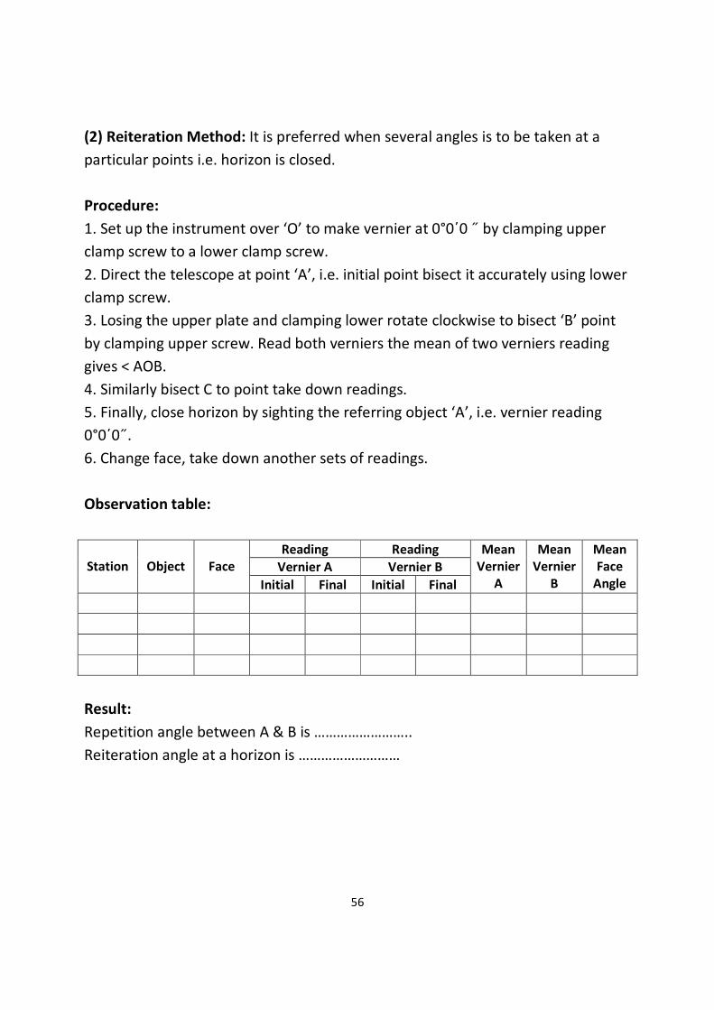
(2) Reiteration Method: It is preferred when several angles is to be taken at a
particular points i.e. horizon is closed.
Procedure:
1. Set up the instrument over ‘O’ to make vernier at 0°0΄0 ˝ by clamping upper
clamp screw to a lower clamp screw.
2. Direct the telescope at point ‘A’, i.e. initial point bisect it accurately using lower
clamp screw.
3. Losing the upper plate and clamping lower rotate clockwise to bisect ‘B’ point
by clamping upper screw. Read both verniers the mean of two verniers reading
gives < AOB.
4. Similarly bisect C to point take down readings.
5. Finally, close horizon by sighting the referring object ‘A’, i.e. vernier reading
0°0΄0˝.
6. Change face, take down another sets of readings.
Observation table:
Station
Object
Face
Reading Reading Mean
Vernier
A
Mean
Vernier
B
Mean
Face
Angle
Vernier A Vernier B
Initial Final Initial Final
Result:
Repetition angle between A & B is ……………………..
Reiteration angle at a horizon is ………………………

57
PLANE TABLE SURVEY
INTRODUCTION TO PLANE TABLE EQUIPMENTS AND ACCESSORIES
Aim: Study of plane table equipments and accessories.
INTRODUCTION TO PLANE TABLE:
Plane table surveying is a graphical method of surveying in which field work and
plotting are done simultaneously in the field.
The plain table consists of the following:
1. Drawing board mounted on a tripod
2. Straight edge called an alidade.
The Drawing Board:
The board is made of well-seasoned wood and varies in size from 40cm x 30 cm to
75cm x 60cm or 50 – 60 cm square.
The Alidade:
The alidade consists of metal or box wood straight edge or ruler about 50cm long.
The welled edge of the alidade is called the fiducially edge.
Accessories to the plane table
1. Trough compass
2. U – frame or plumbing fork
3. Water proof cover.
4. Spirit level or level tube
5. Drawing sheet
6. Pencil or eraser
Trough compass: The compass is used to mark the direction of the meridian on
the paper.

58
U-frame or Plumbing fork: U frame with a plumb bob used for centering the
table.
Water Proof Cover: Water Proof cover protects the sheet from rain.
Spirit level or level tube: A level tube is used to level the plane table.
Drawing sheet: The drawing sheet is fixed on the top of the drawing board.
Pencil and eraser: A pencil is used for constructing lines and eraser is used for
erasing lines after completion of the plan.
SETTING UP THE PLANE TABLE
The setting up the plane table includes the following three operations.
1. Centering the plane table
2. Leveling the plane table
3. Orientation of plane table
CENTERING THE PLANE TABLE:
The table should be set up at a convenient height for working say about 1m. The
legs of tripod should be spread well apart and firmly fixed in to the ground. The
table should be approximately leveled by tripod legs and judging by the eye.
Then the operation of centering is carried out by means of U-frame and plumb
bob. The plane table is exactly placed over the ground station by U-frame and
plumb bob.
LEVELING THE PLANE TABLE:
The process of leveling is carried out with the help of level tube. The bubble of
level tube is brought to center in two directions, which are right angles to each
other. This is achieved by moving legs.
59
ORIENTATION OF PLANE TABLE:
The process of keeping the plane table always parallel to the position, which is
occupied at the first station, is known as orientation. When the plane table is
oriented, the lines on the board are parallel to the lines on the ground.
60
SETTING UP THE PLANE TABLE AND PLOTTING A FEW POINTS BY RADIATION
METHOD
Aim: Setting up the plane table and plotting a few objects by radiation method.
Apparatus:
1) Plane table
2) Tripod
3) Alidade
Theory:
RADIATION: The plane table is set up over only one station from which the
whole traverse can be commanded. It is suitable for survey of small areas.
Procedure:
1) Select a point “O” so that all points to be located are visible from it.
2) Set up the table at “O”, level it, and do centering.
3) SELECT A POINT “O” on the sheet so that it is exactly over station “O” on the
ground.
4) Mark the direction of the magnetic meridian.
5) Centering the alidade on “O”, BISECT the objects of traverse A, B, C and D.
6) Measure the distances OA, OB, OC and OD and plotted to convenient scale to
locate a, b, c and d respectively.
7) Join the points a, b, c and d on the paper.
Result:
61
PLOTTING BUILDING AND OTHER FEATURES OF THE COMPASS BY INTERSECTION
METHOD
Aim: Plotting building and other features of the compass by Intersection method.
Apparatus:
1) Plane table
2) Tripod
3) Alidade
Procedure:
1) Select two points P and Q such that the points (building corners) to be plotted
are visible from their stations.
2) Set the table on P and locate on the sheet.
3) Pivot on P bisect Q draw a ray.
4) Measure the distance PQ and locate Q on the sheet to a convenient scale.
5) Now ‘PQ’ is known as the base line.
6) Pivot ‘p’ bisects the inaccessible objects A and B (building corners) and draw
rays.
7) Shift the table to ‘a’ such that ‘q’ is over Q and do temporary adjustments.
8) Place the alidade along ‘qp’ and the rotate the table till p is bisected clamp
table.
9) Pivot on ‘q’, bisect the objects A and B and draw rays.
10) The instruction of rays drawn from P and Q will give the points ‘a’ and ‘b’.
11) To check the accuracy measured AB and compare with plotted distance ab.
12) The same procedure is applied for other features of the campus. Each point is
bisected from two stations.
Result:

62
TRAVERSING AN AREA BY PLANE TABLE
Aim: Traversing method is used for running survey lines of a closed or open
traverse.
Apparatus:
1. Plane table
2. Tripod
3. Alidade
Procedure:
1) Select the traverse stations A,B,C,D,E etc on the ground.
2) Set the table on starting station ‘a’ and perform temporary adjustments.
3) Mark the magnetic meridian.
4) Locate A on the sheet as ‘a’.
5) Pivot on ‘a’ bisect the next station B and draw a ray
6) Measure the distance AB and locate ‘b’ on the sheet with a suitable scale.
7) Shift the table to next station B, set the table over B, and do temporary
adjustments.
8) Place the alidade along ‘ba’ and bisect A for doing orientation of plane table.
9) Pivot on b bisect c draw a ray
10) Measure the distance BC and locate ‘c’ on the sheet with the suitable scale.
11) Report the same procedure at every successive station until the traverse is
completed.
NOTE: by using radiation method, intersection and traversing methods we can
locate the points on the paper, which were already on the ground. By using
algebraic formulae, we can calculate the area of the given land.
FORMULAE:
1) Area of a triangle = ½ * base *height
2) Area of a square = side * side
3) Area of a rectangle = length * breadth

63
4) Area of a trapezium = ½ * (a + b) * h
a, b are the parallel sides. h is the distance between parallel sides.

64
CHAIN TRIANGULATION AROUND A BUILDING
Aim: To chain around the building to cover small area by chain triangulation
Apparatus:
• Chain 20m / 30m 1 No.
• Arrows 10 Nos.
• Ranging rods 4 Nos.
• Pegs 4 Nos.
• Tape 20m/30m
• Cross staff 1 No.
Procedure:
• Select three survey stations A, B and C such that from each survey station
the other two Stations are visible.
• Mount ranging rods at survey stations A, B and C.
• Fix the intermediate stations along the chain line AB, BC and CA by ranging.
• Measure the offsets of the corners of the building either perpendicular or
oblique.
• Each point requires two measurements from two definite reference points
on the same line or from two adjacent chain lines.
• Measure the points which are very far away from the main chain lines from
tie line i.e. the corners points of building R and S.
• Measure the check line CD.
65
Result:
From the recorded measurements of the building, calculate area.
Note:
The student should prepare a layout of the given area covering building roads etc
66
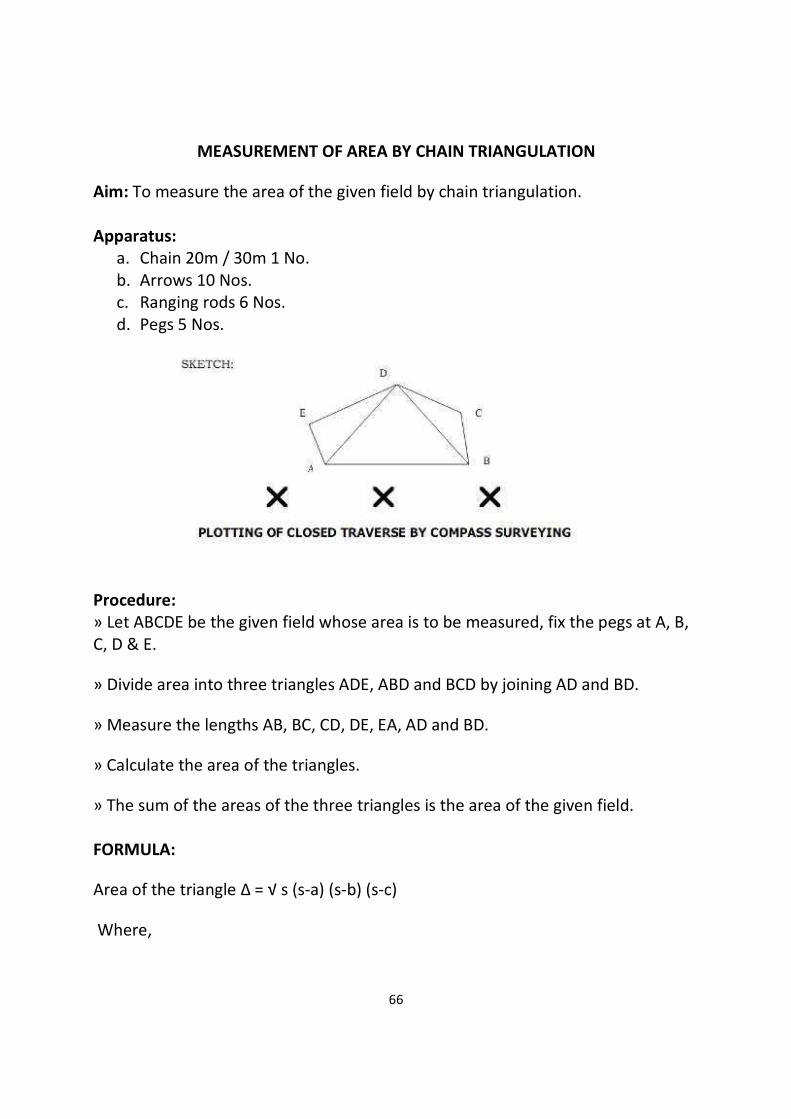
MEASUREMENT OF AREA BY CHAIN TRIANGULATION
Aim: To measure the area of the given field by chain triangulation.
Apparatus:
a. Chain 20m / 30m 1 No.
b. Arrows 10 Nos.
c. Ranging rods 6 Nos.
d. Pegs 5 Nos.
Procedure:
» Let ABCDE be the given field whose area is to be measured, fix the pegs at A, B,
C, D & E.
» Divide area into three triangles ADE, ABD and BCD by joining AD and BD.
» Measure the lengths AB, BC, CD, DE, EA, AD and BD.
» Calculate the area of the triangles.
» The sum of the areas of the three triangles is the area of the given field.
FORMULA:
Area of the triangle ∆ = √ s (s-a) (s-b) (s-c)
Where,

67
S = (a + b+ c) / 2
A, b, c, are the sides of the triangle.
Result:
The area of the given field = _______ Square meter.

68
SETTING OUT STRAIGHT LINES AROUND A BUILDING
Aim:
To measure the distance between two points on a level ground by direct ranging
To set out straight lines around a building
To measure the offset distance from the building
Apparatus: ranging poles, chain, arrows, pegs, measuring tape.
Procedure:
• Fix the ranging rods at the two given stations, where pegs are already
driven on the ground.
• The follower stands behind station A and directs the leader, with ranging
rod to come in line with AB by signals of ranging.
• When the ranging rod comes in the line of AB the follower directs the
leader to fix the ranging rod in position.
• Let the intermediate point be C which should be less than 20m / 30 m
• Now the leader takes another ranging rod and stands between A and B
about 2/3 distance from A
• The follower directs the leader to come in line of AB by using signals of
ranging.
• As and when the point is located in the line of AB the follower instructs to
fix the ranging rod in position.

69
• Let the other intermediate position be D which is less than 20 m / 30 m
from B
• Now A, B, C and D are in a straight line. Now the leader and follower
measure the distance by measuring along A, C, D, B.
Results:
The distance between AB = __________ m.
The distance between AC = __________ m.
The distance between CD = __________ m.
The distance between DB = __________ m.
The offset distance is = __________ m.
From the recorded measurements of the building, calculate area.

70
DETERMINATION OF DISTANCE AND REDUCE LEVEL OF ELEVATION POINT BY
TACHOMETRIC OBSERVATIONS.
Aim: To determined distance and reduce level of elevation point by Tachometric
observations.
Apparatus: Tachometer, leveling staff, pegs, etc.
Theory:
There are two constants i.e. multiplying constant (K), and additive constant(C)
these are computed by taking observations.
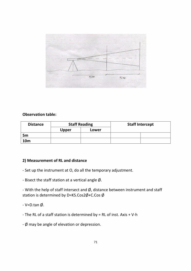
(1) Determination of Tachometric Constants
Procedure:
- Measure a line OA 10 m long on a fairly level ground with a steel tape and fixed
pegs along a distance of 5m.
- Set up the instrument over O, obtained the staff intersect by taking stadia
reading on the staff truly vertical on each peg.
- On substituting values of D and S in equation D=KS+C, we get a equation when
showed in pairs and get the values of k and C.
71
Observation table:
Distance Staff Reading Staff Intercept
Upper Lower
5m
10m
2) Measurement of RL and distance
- Set up the instrument at O, do all the temporary adjustment.
- Bisect the staff station at a vertical angle Ø.
- With the help of staff intersect and Ø, distance between instrument and staff
station is determined by D=KS.Cos2Ø+C.Cos Ø
- V=D.tan Ø.
- The RL of a staff station is determined by = RL of inst. Axis + V-h
- Ø may be angle of elevation or depression.

72
Station
Point
Staff
Station
Vertical
Angle
Staff Reading H.I.
Upper Middle Lower
O P
Result:
R.L of P point is ………..
Distance of P point from station is………

73
SETTING UP THE COMPASS – OBSERVATION OF BEARINGS
Aim: To perform station adjustments and to observe magnetic bearings using a
prismatic compass.
Apparatus: Prismatic compass, Tripod and Ranging rods etc.
Sketch:
Procedure:
The following station adjustments are to be done at each station where the
compass is set up.
1. CENTERING:
a. Centering is the process of keeping the prismatic compass over the
station point.
b. By moving the legs of the tripod suitably, centering will be done.
c. Centering is checked by dropping a stone so that it falls on the top of the
peg.
2. LEVELING:
a. Leveling is the process of making the compass exactly horizontal.
b. Level the compass by means of a ball and socket arrangements.
c. When the compass is leveled, the aluminum ring swings freely.
3. FOCUSSING: To adjust the height of the prism so that the observations can be
read clearly.
N A
B
S c
O
74
4. OBSERVING BEARINGS:
a. Set up the prismatic compass over station “O” and perform station
adjustments.
b. Rotate the compass till the line of sight bisects the object at “A”.
c. Read the graduated ring through prism. The reading directly gives the
magnetic bearing of “OA” in whole circle bearing system.
d. Follow the same procedure to observe the magnetic bearings “OB” and
“OC”.
Calculations and Results:
Tabular form
S/N. STATION SIGHTED TO W.C.B.

75
TRAVERSING WITH PRISMATIC COMPASS AND CHAIN - CALCULATION OF
INCLUDED ANGLES
Aim: To find the bearings of various station points and to calculate the included
angles.
Apparatus: Prismatic compass, tripod, ranging rods etc.
Sketch:
Procedure:
a. Let “O” be the instrument station selected from which other points are
visible.
b. Complete all station adjustments like setting, centering and leveling
accurately.
c. Sight the object “A” looking through the prism vane while the object
vane is directed towards the object.
d. Observe the bearing by looking through the prism. Enter the readings in
a tabular form.
e. Repeat the process at all objects stations B,C,D etc and enter the
readings.
Formula:
Included angle: bearing of 2nd line bearing of first line. (If the value is more than
180o, then, subtract the value from 360
o).
N A
B
S c
O

76
Calculations and Results:
Tabular form
S/N. STATION SIGHTED TO W.C.B.
77
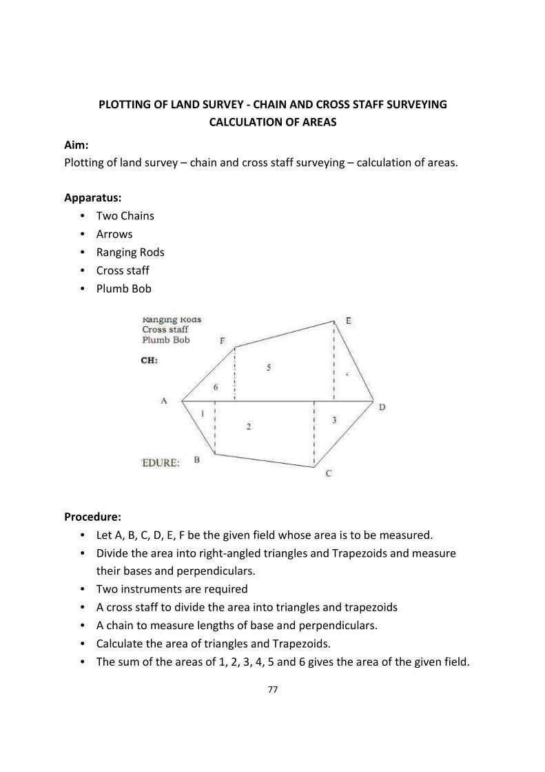
PLOTTING OF LAND SURVEY - CHAIN AND CROSS STAFF SURVEYING
CALCULATION OF AREAS
Aim:
Plotting of land survey – chain and cross staff surveying – calculation of areas.
Apparatus:
• Two Chains
• Arrows
• Ranging Rods
• Cross staff
• Plumb Bob
Procedure:
• Let A, B, C, D, E, F be the given field whose area is to be measured.
• Divide the area into right-angled triangles and Trapezoids and measure
their bases and perpendiculars.
• Two instruments are required
• A cross staff to divide the area into triangles and trapezoids
• A chain to measure lengths of base and perpendiculars.
• Calculate the area of triangles and Trapezoids.
• The sum of the areas of 1, 2, 3, 4, 5 and 6 gives the area of the given field.
78
Formula:
Area of the right angled triangle = ½ Base x Height
Area of Trapezoid = ½ ( a + b) h
Where,
a, b are the parallel sides
h is the distance between the parallel sides.
Result:
The area of the measured field is ……………………………… m

79
PLOTTING OF PERPENDICULAR AND OBLIQUE OFFSETS
Aim: Plotting of perpendicular and oblique offsets
Apparatus:
• Metric chain
• Cross staff
Procedure:
• Run a chain line between the given station A and B
• Hold cross staff vertically on the chain line where the perpendicular from
point “p” is expected to meet.
• Turn the cross staff until one pair of opposite slit is directed to a ranging
rod fixed at B (forward point)
• Look through the other pair of slits and see that the point ‘p’ bisect to
which the offset is to be taken.
• If not, the cross staff is moved in forward or backward on the chain line AB
until the line of sight bisects the point ‘p’.
• Measure the perpendicular offset distance PQ.
Result:
a. Perpendicular offset distance PQ = ………………………………… m
b. Represent the accomplished task diagrammatically.

80
FLY LEVELING (SIMPLE LEVELING)
Aim: To find the difference in elevation between two points
Apparatus:
• Dumpy level
• Leveling staff
Procedure:
• Let A and B be the two given points whose difference in elevation is to be
found.
• Set the level at a convenient point O1, perform temporary adjustments and
take B.S on A
• Take FS on the Point C
• Shift the instrument to point O2, perform temporary adjustments and take
B.S on C.
• Take F.S. on D.
• Shift the instrument to point O3, perform temporary adjustments and take
B.S on D
• Take F.S on B.
• Find the difference in elevation between A and B by both the methods.
Result:
Difference in elevation between A and B = ……………

81
DIFFERENTIAL LEVELING INVOLVING INVERT LEVELS REDUCTION BY H.I AND RISE
AND FALL METHODS
Aim: To find the levels of certain points, which lie above the line of collimation.
Theory:
When the point under observation is higher than the line of Sight, should be kept
inverted on the overhead point Keeping the foot of the staff touching the point,
and read should be taken and recorded in the field book with a Negative sign
indicating invert level.
Apparatus:
• Dumpy level
• Leveling staff
Procedure:
• Setup the instrument at a convenient point and take the B.S on the
benchmark.
• Place the staff in the inverted position at the required staff stations, which
are lying above the line of collimation.
• Take the reading on the staff and note it in the field book with a negative
sign.
• Calculate the R.L of the required ff station.
• Repeat the process for all invert staff readings.
• For all other points the procedure to find R.L is similar to that in the
previous exercises.
Result:
Difference in elevation between A and B = ……………

82
TAKING OUT LEVELS OF VARIOUS POINTS AND BOOKING IN A LEVEL FIELD BOOK
Aim: Taking the levels of various points with Single setup, booking in a level field
book.
Apparatus:
• Dumpy level
• Leveling staff
Procedure:
• Set the level at a convenient point.
• Perform the temporary adjustments.
• Hold the staff vertically over the Benchmark, observe the staff reading and
write in the B.S column of the field book.
• Hold the staff at other points and note the staff reading in the I.S column of
the field book.
• Hold the staff on the last point and enter the staff reading in the F.S column
of the field book.
• Find R.L. of all the points using both methods.
• Apply arithmetical check.
Calculations and Results:
ST. NO.
B.S.(M) I.S.(M) F.S.(M) R.L.(M) REMARKS
ARITHEMETIC CHECK:
∑B.S. - ∑F.S. = Last R.L. – First R.L.

83
FLY LEVELING (DIFFERENTIAL LEVELING)
Aim: To ascertain the difference of elevation between any two points.
Apparatus:
• Dumpy level
• Leveling staff
• Tripod
Theory:
Differential leveling is the method of direct leveling the object of which is to
determine difference in elevations of two points regardless of horizontal position
of point with respect to each other, when points are apart it may be necessary to
set up the instrument several times. This type of Leveling is also known as “FLY-
LEVELLING”.
Procedure:
• Instrument level is setup at convenient positions near first point (say A).
• Temporary adjustments should be done, (setting up, leveling up,
elimination of a par-allot) are Performed.
• First sight of B.M (point of known elevation) is taken and reading is entered
in Back Sight column, Intermediate sight column.
• If distance is large instrument is shifted, the instrument becomes turning
point (or) changing point.
• After setting up instrument at new position, performing temporary
adjustment and Take back sight as turning point.
• Thus turning point will have both back sight and fore sight readings.
• Link wise the process is repeated till last point (say B) is reached.
• Readings are entered in a tabular form and Reduced levels are calculated
either by height of instrument method (or) and fall method.
ARITHEMETIC CHECK:
∑B.S. - ∑F.S. = ∑Rise - ∑Fall = Last R.L. – First R.L.

84
Result:
Difference of elevation between two given points is ______ M.
SIMPLE LEVELING
ST. NO.
B.S.(M) I.S.(M) F.S.(M) H.I.(M) R.L.(M) REMARKS
Result:
Difference between points = ___________m.
DIFFERENTIAL LEVELING
ST. NO. B.S.(M) I.S.(M) F.S.(M) H.I.(M) R.L.(M) REMARKS
ARITHEMETIC CHECK:
∑B.S. - ∑F.S. = Last R.L. – First R.L.
Result:
Difference of level A and B is = ___________m.

85
PROFILE LEVELLING (Longitudinal section & cross section, L.S & C.S)
Aim: Determining the elevation at various points on ground at regular interval
Apparatus:
• Dumpy level
• Leveling staff
• Tripod
• Peg
Procedure:
• Divide the proposed center line of a given work at regular intervals
• Fix the level and do station adjustments
• BS on Bench Mark
• IS on intermediate points
• FS on Change points and End point
• Record the values in field book in respective columns
Calculations and Results:
PROFILE LEVELING:
ST.
NO.
LEFT CENTER RIGHT B.S.(M) I.S.(M) F.S.(M) H.I.(M) R.L. REMARKS
ARITHEMETIC CHECK:
∑B.S. - ∑F.S. = Last R.L. – First R.L.

86
STUDY OF DUMPY LEVEL AND LEVELING STAFF
Aim: To study the components of a dumpy level and leveling staff.
Apparatus:
• Dumpy level
• Leveling staff
Theory:
DUMPY LEVEL
KEY
1. Leveling head
2. Telescope
3. Eye-piece
4. Diaphragm
5. Focusing screw
6. Ray-shade
The Major Components of a Dumpy Level
87
TELESCOPE:
It contains two metal tubes, one of which slides within the other one-tube carries
the object glass and the second one carries eyepiece and diaphragm.
FOCUSSING SCREW:
The telescope is focused by turning the focusing screw either forward or
backward.
BUBBLE TUBES:
The telescope is attached with two bubble tubes. One is longitudinal and the
other is cross bubble tube. These two are placed at right angles to each other.
DIAPHRAGM: It carries cross hairs.
TRIBRACH & TRIVET:
The telescope with vertical spindle is supported by two parallel triangular Plates.
The upper plate is called tribrach and the lower plate is called trivet.
FOOT SCREWS:
By turning the foot screws, the tribrach can be raised or lowered to bring the
bubble to the center of its run.
LEVELLING STAFF
It is used for measuring the vertical distance of the points above or below the
horizontal line of sight. The different staves in use are;
1. Sop with telescope staff 2. Folding staff
3. Solid staff 4. Target staff
SOP WITH TELESCOPE STAFF:
It is usually arranged in three telescopic lengths. The staff is 4m long when fully
extended. The top length 12.5m is solid slides into the central box of length
12.5m, which again slides in the bottom box of 1.50m long. The staff is provided

88
with brass spring catches to keep the extended length in position. The meter
numerals are marked on the left side and are red. The decimeter numerals are
marked on the right side and are pointed in black. The background is painted in
white. The smallest division on this staff is 5mm. The graduations are marked
erect and are seen inverted when viewed through the Telescope.
FOLDING STAFF:
It is made of well-seasoned timber such as deodar, blue pine or aluminum. It is
4m long, 75mm wide, 18mm thick. It has two lengths of 2m each which are
connected at the middle by a hinge so that the upper portion can be folded over
the lower one. The minimum division on the staff is 5mm. lengths of meter in
numerals are marked on the left and painted in black. The entire background is
painted in white. The graduations are inverted and hence when viewed through
the telescope, they appear erect.
SOLID STAFF:
It consist only one length and is usually 3m long. It is also graduated in Divisions of
5mm. This is used for precise leveling work.
TARGET STAFF:
It consists of two lengths, one sliding over the other. It is graduated from top
downwards. The target is equipped with venire, which is adjusted by the staff
man. The target is to be moved along the rod until its center is bisected by the
line of sight. The target is then clamped and reading is taken. Target staves are
used when the Sights are long, say more than 100m.
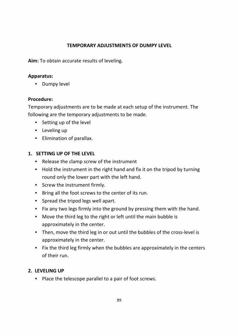
89
TEMPORARY ADJUSTMENTS OF DUMPY LEVEL
Aim: To obtain accurate results of leveling.
Apparatus:
• Dumpy level
Procedure:
Temporary adjustments are to be made at each setup of the instrument. The
following are the temporary adjustments to be made.
• Setting up of the level
• Leveling up
• Elimination of parallax.
1. SETTING UP OF THE LEVEL
• Release the clamp screw of the instrument
• Hold the instrument in the right hand and fix it on the tripod by turning
round only the lower part with the left hand.
• Screw the instrument firmly.
• Bring all the foot screws to the center of its run.
• Spread the tripod legs well apart.
• Fix any two legs firmly into the ground by pressing them with the hand.
• Move the third leg to the right or left until the main bubble is
approximately in the center.
• Then, move the third leg in or out until the bubbles of the cross-level is
approximately in the center.
• Fix the third leg firmly when the bubbles are approximately in the centers
of their run.
2. LEVELING UP
• Place the telescope parallel to a pair of foot screws.

90
• Bring the bubble to the center of its run by turning the foot screws equally
either both inwards and both outwards.
• Turn the telescope through 90º so that it lies over the third foot screw.
• Turn this third foot screw so that the bubble corners to the center of its
run.
• Bring the telescope back to the original position without reversing the eye-
piece and object glass.
• Repeat the above operations until the bubble remains in the center of its
run in both the positions.
• Turn the telescope through 180º and check whether the bubble remains
central.
3. ELIMINATION OF PARALLAX:
• Remove the lid from the object glass.
• Hold a sheet of white paper in front of the object glass.
• Move the eyepiece in or out until the cross hairs are distinctly visible.
• Direct the telescope towards the staff.
• Turn the focusing screw until a clear and sharp image in formed in the
plane of the cross hairs.
TABLE FOR HEIGHT OF INSTRUMENT (H.I.) METHOD
STATION
READINGS HEIGHT OF
INSTRUMEN
T
REDUCE
D
LEVEL
REMARK
S
BACK
SIGHT
INTER
SIGHT
FORE
SIGHT
H.I. = R.M. of B.M. + B.S.
R. L. of other station points = H.I. – I.S. of F.S.
ARITHMETIC CHECK:
∑B.S. - ∑F.S. = Last R.L. – First R.L.

91
FOR RISE AND FALL METHOD
STATIO
N
READINGS
RISE
FALL
R.L.
REMARKS BACK
SIGHT
INTER
SIGHT
FORE
SIGHT
ARITHEMETIC CHECK:
∑B.S. - ∑F.S. = ∑Rise - ∑Fall = Last R.L. – First R.L.
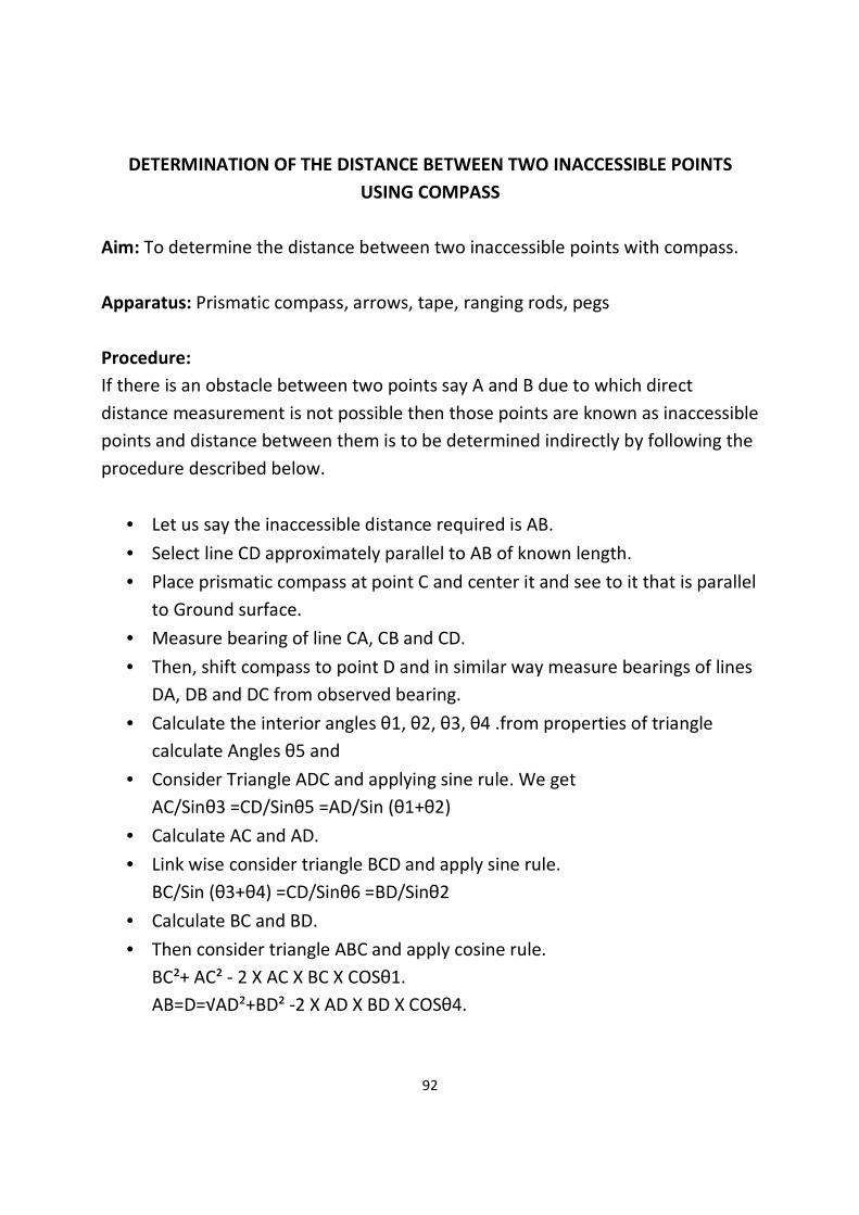
92
DETERMINATION OF THE DISTANCE BETWEEN TWO INACCESSIBLE POINTS
USING COMPASS
Aim: To determine the distance between two inaccessible points with compass.
Apparatus: Prismatic compass, arrows, tape, ranging rods, pegs
Procedure:
If there is an obstacle between two points say A and B due to which direct
distance measurement is not possible then those points are known as inaccessible
points and distance between them is to be determined indirectly by following the
procedure described below.
• Let us say the inaccessible distance required is AB.
• Select line CD approximately parallel to AB of known length.
• Place prismatic compass at point C and center it and see to it that is parallel
to Ground surface.
• Measure bearing of line CA, CB and CD.
• Then, shift compass to point D and in similar way measure bearings of lines
DA, DB and DC from observed bearing.
• Calculate the interior angles θ1, θ2, θ3, θ4 .from properties of triangle
calculate Angles θ5 and
• Consider Triangle ADC and applying sine rule. We get
AC/Sinθ3 =CD/Sinθ5 =AD/Sin (θ1+θ2)
• Calculate AC and AD.
• Link wise consider triangle BCD and apply sine rule.
BC/Sin (θ3+θ4) =CD/Sinθ6 =BD/Sinθ2
• Calculate BC and BD.
• Then consider triangle ABC and apply cosine rule.
BC²+ AC² - 2 X AC X BC X COSθ1.
AB=D=√AD²+BD² -2 X AD X BD X COSθ4.
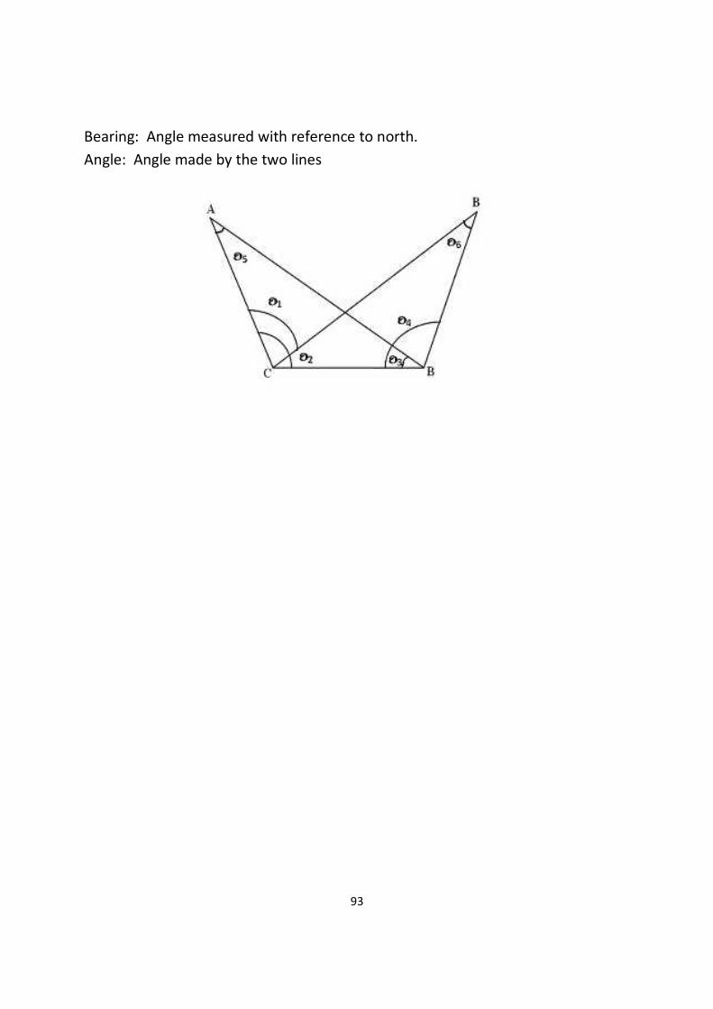
93
Bearing: Angle measured with reference to north.
Angle: Angle made by the two lines

94
SURVEYING A GIVEN AREA BY PRISMATIC COMPASS (CLOSED TRAVERSE) AND
PLOTTING AFTER ADJUSTMENT
Aim: To run a closed traverse by prismatic compass and plot the same
Apparatus: Prismatic compass, tape, chain, arrows, pegs, ranging rods.
Theory:
Closed traverse is generally run around a structure. It is fined as a series of
connected lines whose directions and lengths are determined precisely.
Procedure:
The following procedure is adopted to run a closed compass traverse.
• Let us say we have to run a closed compass traverse ABCDEA.
• Set the prismatic compass at point A. center it and level it.
• Take bearings of traverse lines AB and AE.
• Shift the compass to point B center it and level it. Take the bearings BC and
BA.
• Link-wise complete the traverse as shown in the figure below.
• Measure the length of traverse line AB, BC, CD, DE, and EA.
• Record the observation in tabular form.
• Care must be taken to see that the stations are not affected by local
attractions. If they are affected corrections to local attractions should be
applied first and then, the traverse should be plotted with corrected
bearings.
• Simplest method of plotting is angle and distance method with a
protractor. If last point is falling short by some distance in meeting the first
point then it means that there is a closing error. So, traverse should be
adjusted by “Bow ditch’s graphical method”.

95
Calculations:
LINE FORE BEARING BACK BEARING LENGTH (M)
Results:
The adjusted traverse with bearings and length is to be shown on a Drawing
sheet.

96
TRAVERSING WITH PRISMATIC COMPASS AND CHAIN, OPEN TRAVERSE AND
RECORDING
Aim: To perform the compass survey in open traverse formed by series of
connected straight lines.
Apparatus: Prismatic compass, tripod, tape, chain, arrows and ranging rods.
Procedure:
• Set the instrument at the starting station ‘A’ and perform all the necessary
adjustments.
• Sight the next station ‘B’, take fore bearing of ‘AB’ and measure the
distance ‘AB’.
• Take F.B of ‘AE which provides check; similarly bearing of any line AC, CE,
etc. also provides the check.
• Shift the instrument to subsequent station ‘B’ after fixing the instrument.
• Sight the previous station ‘A’ and observe the reading, which gives the B.B.
of AB.
• Sight next station ‘C’ observe F.B of BC and measure the distance BC.
• Locate the details surrounding the traverse station if necessary, by taking
Bearings or lengths or both from chains line.
• Repeat the process at every station.
• It is to be noted that first and last stations have only fore bearing and back
Bearings respectively.

97
• Take back bearings of the first point from the last point.
• Enter the reading in a tabular form.
S/No. LINE LENGTH F.B. B.B. REMARKS
1.
2.
3.
4.
Results:
The difference between fore bearing and back bearing of each line should be
180º, if no local attraction exists at either station.
QUESTIONS
• What is the purpose of prismatic compass in surveying?
• State when do you go for compass surveying?
• For what a mirror is provided to the object vane?
• Where is the 180º marked on the graduated ring?
• What is the least reading that can be read from a compass?
• State the reason why the graduations of prismatic compass are written
inverted.
• Define the whole circle bearing?
• Define the reduced bearing?
• Define fore bearing and back bearing?
• What is the difference between fore bearing and back bearing?
• The fore bearing of a line 60º 30’, find its back bearing?
• Convert 80º30’, 130º40’into reduced bearing?
• Convert 52º30’ into whole circle bearing?
• What is meant by traverse? Explain the check applied to a closed traverse?
• Define local attraction. How do you detect it?
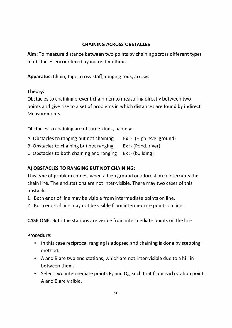
98
CHAINING ACROSS OBSTACLES
Aim: To measure distance between two points by chaining across different types
of obstacles encountered by indirect method.
Apparatus: Chain, tape, cross-staff, ranging rods, arrows.
Theory:
Obstacles to chaining prevent chainmen to measuring directly between two
points and give rise to a set of problems in which distances are found by indirect
Measurements.
Obstacles to chaining are of three kinds, namely:
A. Obstacles to ranging but not chaining Ex :- (High level ground)
B. Obstacles to chaining but not ranging Ex :- (Pond, river)
C. Obstacles to both chaining and ranging Ex :- (building)
A) OBSTACLES TO RANGING BUT NOT CHAINING:
This type of problem comes, when a high ground or a forest area interrupts the
chain line. The end stations are not inter-visible. There may two cases of this
obstacle.
1. Both ends of line may be visible from intermediate points on line.
2. Both ends of line may not be visible from intermediate points on line.
CASE ONE: Both the stations are visible from intermediate points on the line
Procedure:
• In this case reciprocal ranging is adopted and chaining is done by stepping
method.
• A and B are two end stations, which are not inter-visible due to a hill in
between them.
• Select two intermediate points P1 and Q1, such that from each station point
A and B are visible.

99
• Two persons take up the positions P1 and Q1 with ranging rods.
• First the person standing at P1 directs the person at Q1 to come in line of P1
B, and his new position will be Q2.
• Next, the person standing at Q2, directs the person at pi, to come in line of
Q2 A, and his new position will be P2.
• Next, the person standing at P2, directs the person at Q2, to come in line of
P2B, and his new position will be Q3.
• This process is continued until the intermediate points P and Q are located
in such a way that the person standing at P, see Q and B in the line, and
the person standing at Q, see P and A in the line.
• Distance AB = AP+PQ+QB
CASE TWO:
The end stations are not visible from the intermediate points on the line. This is
the case when trees, bushes or jungle comes across the chain line. In this case the
method of random line is most suitable.
Procedure:
• In the figure above, let PQ be the line in which P and Q are not visible from
intermediate point on it.
• Through P draw a random line PQ in any convenient direction but as nearly
to Towards Q as possible.
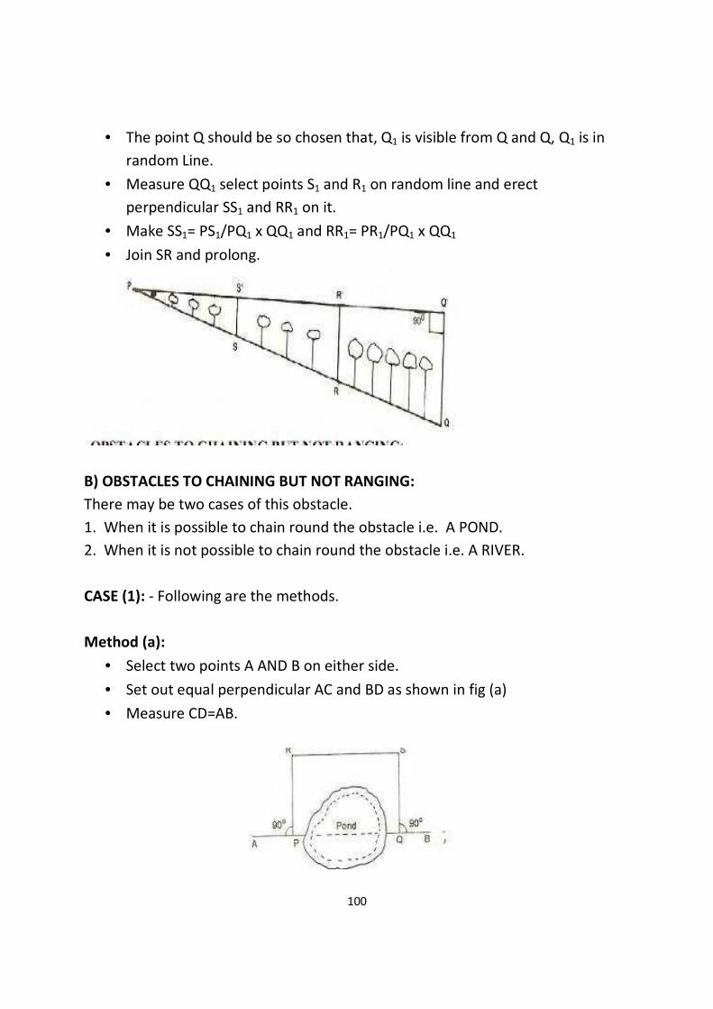
100
• The point Q should be so chosen that, Q1 is visible from Q and Q, Q1 is in
random Line.
• Measure QQ1 select points S1 and R1 on random line and erect
perpendicular SS1 and RR1 on it.
• Make SS1= PS1/PQ1 x QQ1 and RR1= PR1/PQ1 x QQ1
• Join SR and prolong.
B) OBSTACLES TO CHAINING BUT NOT RANGING:
There may be two cases of this obstacle.
1. When it is possible to chain round the obstacle i.e. A POND.
2. When it is not possible to chain round the obstacle i.e. A RIVER.
CASE (1): - Following are the methods.
Method (a):
• Select two points A AND B on either side.
• Set out equal perpendicular AC and BD as shown in fig (a)
• Measure CD=AB.

101
Method (b):
• Set out AC perpendicular to chain line as shown in fig (b)
• Measure AC and BC
• The length AB is calculated from the relation
AB=√BC²-AC²
Method (c):
• By cross staff find a point C which subtends 90° with A and B as Shown In fig
(C). AC and BC.
• The length AB is calculated from relation AB= √AC²+BC².
Method D:
• Select any point E and range C in line with AE, making AE = EC
• Range D in line with BE and make BE=ED as shown in fig (d).
• Measure CD then AB=CD.

102
CASE (2): - Following are the methods.
Method (a):
• Select point B on one side and A and C on the other side.
• Erect AD and CE as perpendicular to AB and range B, D and E in One line as
shown in fig (e).
• Measure AC, AD and CE.
• If a line DF is drawn parallel to AB cutting CE in F perpendicularly.
• The triangle ABD and FDE will be similar.
Method (b):
• Locate a point R in such a way that it makes 900 with PQ.
• Range S in line with PR and make PS = PR.
• At S erect a perpendicular ST to cut the line AB at T.
• Then PQ =PT
C) OBSTACLES TO BOTH CHAINING AND RANGING:-
A Building is the typical example of this type of obstacles. The problem lies in
prolonging the line beyond the obstacle and determines the distance across it
Method (a):
• Choose two points A and B to one side erect perpendicular AC and BD of
equal length.
• Join CD and prolong It pass the obstacles.

103
• Choose two points E and F on CD and erect perpendicular EG and FH equal
to AC or BD as shown in fig (g).
• Join GH and prolong it. Measure DE.
• BG=DE.
Method (b):
• Point A and erect a perpendicular AC of any convenient Length.
• Select other point B on chain line such that AB=AC.
• Join B and C and prolong it. To any convenient point D.
• At D set a right angle DE such that DE=DB.
• Choose another point F on DE such that DF=DC with F as centre and AB as
radius. Draw an arc with E as center draw another arc of same Radius to cut
previous arc in G.
• Join GE which will be in range with chain line. Refer the fig (h).
• Measure CF then AG=CF.
104
QUESTIONS
1) What is surveying?
2) What are the principles of surveying?
3) How many links are provided in a 20-meter metric chain?
4) Differentiate between ranging rod and offset rod.
5) Define the terms base line tie line and check line.
6) When is the reciprocal ranging adopted?
7) What is meant by perpendicular and oblique offset?
8) What are the instruments required for erecting perpendicular offset.
9) What is meant by survey station?
10) What is meant by ranging?

105
CHAINING A LINE BY INDIRECT RANGING
Aim: To chain a line across a hill or high ground that obstructs visibility of both
ends of the line.
Apparatus:
• Chain 20m / 30m - 1 No.
• Arrows - 10 Nos.
• Ranging rods - 4 Nos.
Procedure:
• Fix the two ranging rods at the given stations A and B which are not visible
due to raising ground.
• Select two intermediate points M1 and N1 such that from each point both
A and B are visible.
• The person at M1 directs the person at N1 to move to a new position N2 in
line with M1B.
• The person at N2 then directs the person at M1 to move to a new position
M2 in line with N2A.
• The person at M2 directs the person at N2 to a new position N3 in line with
M2B.
• The person at N3 directs the person at M2 to a new position M3 in line with
N3A.

106
• The process is repeated till the points M and N are located in such a way
that M finds the person at N in line with AB and the person at N finds the
person at M in line with AB.
• After fixing the points M and N, other points are also fixed by direct ranging
and the length of the line is measured.
Results:
Length of AM = ____ m.
Length of MN = ____ m.
Length of NB = ____ m.
Therefore distance of AB = distance AM + distance MN + distance NB
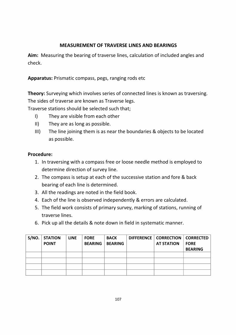
107
MEASUREMENT OF TRAVERSE LINES AND BEARINGS
Aim: Measuring the bearing of traverse lines, calculation of included angles and
check.
Apparatus: Prismatic compass, pegs, ranging rods etc
Theory: Surveying which involves series of connected lines is known as traversing.
The sides of traverse are known as Traverse legs.
Traverse stations should be selected such that;
I) They are visible from each other
II) They are as long as possible.
III) The line joining them is as near the boundaries & objects to be located
as possible.
Procedure:
1. In traversing with a compass free or loose needle method is employed to
determine direction of survey line.
2. The compass is setup at each of the successive station and fore & back
bearing of each line is determined.
3. All the readings are noted in the field book.
4. Each of the line is observed independently & errors are calculated.
5. The field work consists of primary survey, marking of stations, running of
traverse lines.
6. Pick up all the details & note down in field in systematic manner.
S/NO.
STATION
POINT
LINE FORE
BEARING
BACK
BEARING
DIFFERENCE CORRECTION
AT STATION
CORRECTED
FORE
BEARING

108
CORRECTED BACK
INCLUDED ANGLE
CORRECTION
CORRECTED ANGLE

109
TOTAL STATION – HORIZONTAL AND ZENITH ANGLE MEASUREMENT AND
CALCULATION OF X, Y COORDINATES
Aim:
1) To practice setting up a Total Station over a point.
2) To practice measuring horizontal angles to 30” accuracy and measure zenith
angles.
3) To record distances of ‘to’ stations from base station.
4) To determine X, Y coordinates of ‘to’ stations knowing coordinates of occupied
station.
Procedure:
1) Setup Total Station on station assigned to you in the lab (follow the field
demonstration).
Follow the instructions given to you in the last lab (see “Basic Operation
Procedure of Total Station” section of this handout).
2) Enter atmospheric conditions for ‘ppm’ correction and occupied station
information in the Total Station and make it ready for lab experiments.
Steps for Measuring Horizontal Angles
1) Back sight the specified point (Bench Mark GA02) and set Hz angle to zero, as
demonstrated by the instructor.
2) Measure and record distance from this point.
3) Measure and record angle right between this BM and foresight point 11 (Direct
and Reversed). Calculate the average angle. Also, record distance between base
station and point 11.
4) Repeat steps 1-3, except this time you will set Hz angle zero to the last point
you shot at and calculate angle. Keep doing this until you are back to first back
sight station.
5) Close the Horizon: You and your crew mates will take turns to measure angles
as mentioned in step 3. Now compute the horizon closure,
HC = Sum of mean angles - 360°
6) Perform the quality check: HC<Allowable Closure

110
Where Allowable Closure (AC) = ±30”√n; where n= number of angles
Zenith Angles
1) Level the instrument as accurately as possible
2) Point the station you are shooting at and record the Zenith angle in Direct
mode (ZD)
3) Put Total station in reverse mode and shoot that point again and record Zenith
angle in
Reverse mode (ZR)
4) Verify that ZD + ZR = 360 ± 60”
Basic Operation Procedure of Total Station

111
TOTAL STATION – TRAVERSE SIDES & INTERIOR ANGLES
Aim:
1) Tie in all traverse stations: This will be done while you are not involved in taking
measurements.
2) Measure traverse interior angle: Each student will measure at least one interior
traverse angle. This will be done in “shifts”. The first shift stays in the field to take
measurements while other shifts take recovery/ tie-in notes for each station.
3) Write field notes for horizontal angle measurements by repetition: Each
student will use tab sheet provided to report: horizontal angle direct 1D, and the
2nd repetition 1D1R value and the average horizontal angle.
4) Compile data for a complete traverse: Upon the completion of the field work,
you all will share their measurements with other crews and compile data for a
complete traverse. You will have multiple readings for same distance and angles.
Procedure:
Basic Operation Procedure of Total Station
Measuring Horizontal Angles
1) Back sight a given point (B.S. point) and set Hz angle to zero, as shown by the
instructor. Measure and record right interior angles. Always take readings in
clockwise direction.
2) Measure and record distance between the vertex (Total Station point) and the
B.S. point.
3) Measure and record angle right between the B.S. point and foresight (F.S.)
point.
4) Obtain direct and reversed angle readings and calculate their mean for each
angle.
5) Record distances between base station (vertex) and adjoining traverse stations.

112
Recovery Notes
1) Write description of each traverse station (what is it, where is it and also
provide tie-in notes)
2) Provide at least one direction and one distance info or two distances for the
same station from two well known, visible and stable points.
3) Use one complete spread of your field book.