federation and interoperability · 2 1.3.4 background material 3 1.4 relation to other ... 16 5.1.3...
TRANSCRIPT

Copyright 1995 Architecture Projects Management LimitedThe copyright is held on behalf of the sponsors for the time being of the ANSA Workprogramme.
Poseidon HouseCastle ParkCambridge CB3 0RDUnited Kingdom
TELEPHONE: Cambridge (01223) 515010INTERNATIONAL: +44 1223 515010
FAX: +44 1223 359779E-MAIL: [email protected]
ANSA Phase III
Distribution:
Supersedes :
Superseded by :
APM.1514.00.03 Draft 13th September 1995
Request for Comments (confidential to ANSA consortium for 2 years)
Federation and Interoperability
Yigal Hoffner and Ben Crawford
Abstract
The need to exploit new markets as they are opened up by new technology, combined with greatercompetition and greater market accessibility, are causing business processes to change at anever-increasing rate.
To survive in this environment, organisations must become capable of rapid and flexiblereorganisation, and must be ready at very short notice to trade in new markets with differentsuppliers. In order to achieve this, their information systems must be able to accommodatediversity in technology, administrative policies and procedures, and incompatibilities betweenapplications.
This document presents a clear and comprehensive model of interoperability issues. It is intendedto help anyone wishing to understand the general issues raised by interoperability requirements,and to provide strategic guidance. It also provides context and expansion of the issues containedin the OMG Interoperability proposal and contains much information of practical benefit to platformdesigners and system integrators.


Federation and Interoperability


Federation and Interoperability
Yigal Hoffner and Ben Crawford
APM.1514.00.03
13th September 1995

The material in this Report has been developed as part of the ANSA Architec-ture for Open Distributed Systems. ANSA is a collaborative initiative, managedby Architecture Projects Management Limited on behalf of the companiessponsoring the ANSA Workprogramme.
The ANSA initiative is open to all companies and organisations. Further infor-mation on the ANSA Workprogramme, the material in this report, and on otherreports can be obtained from the address below.
The authors acknowledge the help and assistance of their colleagues, in spon-soring companies and the ANSA team in Cambridge in the preparation of thisreport.
Architecture Projects Management Limited
Poseidon HouseCastle ParkCAMBRIDGECB3 0RDUnited Kingdom
TELEPHONE UK (01223) 515010INTERNATIONAL +44 1223 515010FAX +44 1223 359779E-MAIL [email protected]
Copyright 1995 Architecture Projects Management LimitedThe copyright is held on behalf of the sponsors for the time being of the ANSAWorkprogramme.
Architecture Projects Management Limited takes no responsibility for the con-sequences of errors or omissions in this Report, nor for any damages resultingfrom the application of the ideas expressed herein.
APM.1514.00.03 Federation and Interoperability i
Contents
1 1 Introduction1 1.1 The business problem1 1.2 The technical problem2 1.3 This document2 1.3.1 Audience2 1.3.2 Aims2 1.3.3 Structure2 1.3.4 Background material3 1.4 Relation to other documents3 1.5 Acknowledgements
4 2 Overview4 2.1 Document summary5 2.2 Document overview5 2.2.1 Chapter 3: Co-operation between systems5 2.2.2 Chapter 4: Heterogeneity and incompatibility5 2.2.3 Chapters 5-6: Domains, boundaries and transformations5 2.2.4 Chapter 7: Application level transformations and gateways5 2.2.5 Chapter 8: Using gateways to manage domain relationships5 2.2.6 Chapters 9-12: Using interception to manage transformation of
information6 2.2.7 Chapters 13-14: Binding and interface references
7 3 Co-operation between systems7 3.1 Processes necessary to establish co-operation9 3.2 Agreement/Contractual relationship9 3.3 Scenarios of co-operation set up9 3.3.1 Scenario 1
10 3.3.2 Scenario 210 3.3.3 Issues concerning scenarios11 3.4 Hierarchy and Federation
12 4 Heterogeneity and incompatibility12 4.1 Differences between systems12 4.1.1 Authority and contracts13 4.1.2 Administrations and management13 4.1.3 Accounting, billing and remuneration13 4.1.4 Infrastructures and technical relation14 4.1.5 Applications and service description14 4.1.6 Models, semantics and naming
15 5 Domains and boundaries15 5.1 Terminology15 5.1.1 Domains

Contents ANSA Phase III
ii Federation and Interoperability APM.1514.00.03
16 5.1.2 Boundaries16 5.1.3 Paths and gateways17 5.2 Model of interconnected domains17 5.3 A classification of domain boundaries17 5.3.1 Technology boundaries18 5.3.2 Administrative boundaries19 5.3.3 Application boundaries
20 6 Transformations at domain boundaries20 6.1 Types of transformations carried at boundaries20 6.2 Scenarios for information crossing domain boundaries20 6.2.1 Marshalling and unmarshalling20 6.2.2 Activation and passivation21 6.2.3 Addition of information21 6.2.4 Removal of information21 6.2.5 Encryption and decryption21 6.2.6 Name translation22 6.2.7 Transferring information between type systems22 6.2.8 Transferring information between different applications
24 7 Application level transformations and gateways24 7.1 Application level transformations24 7.2 Application level gateways25 7.3 Using Application level gateways25 7.3.1 Gateway as a way of overcoming differences25 7.3.2 Gateway as a way of creating administrative domains26 7.3.3 Gateway as a way of monitoring domain crossing
27 8 Using gateways to manage inter-domain relationships27 8.1 Contracts and relationship between domains28 8.2 Propagation of the inter-domain relationship28 8.3 Trading and interception29 8.4 A computational model of interception
31 9 The phases of the Interception process31 9.1 Interception process phases31 9.1.1 Detection phase31 9.1.2 Recognition phase32 9.1.3 Marking phase32 9.1.4 Resolution phase
33 10 Interception resolution strategies33 10.1 Immediate resolution strategy34 10.2 Deferred resolution strategy34 10.3 Leave-and-Forward resolution strategy34 10.4 Choosing a resolution strategy35 10.5 Level of resolution
36 11 Passing interface references through domain boundaries36 11.1 Crossing domain boundaries36 11.2 Immediate resolution strategy and interface reference passing36 11.2.1 The immediate resolution strategy sequence

ANSA Phase III Contents
APM.1514.00.03 Federation and Interoperability iii
37 11.2.2 Advantages and disadvantages of the immediate resolution strategy37 11.2.3 Requirements placed on distributed platform design38 11.3 Deferred resolution strategy and interface reference passing38 11.3.1 The deferred resolution strategy sequence39 11.3.2 Advantages and disadvantages of the deferred resolution strategy39 11.3.3 Requirements placed on distributed platform design39 11.4 Leave-and-Forward resolution strategy and interface reference passing40 11.4.1 The Leave-and-Forward strategy sequence40 11.4.2 Advantages and disadvantages of the Leave-and-Forward strategy41 11.4.3 Requirements placed on distributed platform design
42 12 Interception implementation issues42 12.1 Overview of design issues for interception and gateways43 12.2 Choosing gateway design options43 12.3 Gateway design options43 12.3.1 Distribution of information about transformations44 12.3.2 Distribution of bindings across gateways44 12.3.3 Distribution of information about bindings45 12.3.4 Resource allocation46 12.3.5 Ordering of composite gateways48 12.4 Impact of design choices on infrastructures
49 13 Binding49 13.1 Binding and interface references49 13.2 Binder policy50 13.3 Binder algorithm
51 14 Interface references and interception51 14.1 Introduction52 14.2 Minimal requirements for interface references52 14.2.1 End-point Naming52 14.3 Interoperability requirements on interface references52 14.3.1 Accommodating alternative routes53 14.3.2 Accommodating different interception strategies54 14.3.3 Manipulating and passing interface references54 14.4 Recommended interface reference structure55 14.4.1 Tagged Profile55 14.4.2 IOR56 14.5 Additional requirements on interface references56 14.5.1 Migration and Relocation56 14.5.2 Integrity checking57 14.5.3 Replication

APM.1514.00.03 Federation and Interoperability 1
1 Introduction
1.1 The business problem
The need to exploit new markets as they are opened up by new technology,combined with greater competition and greater market accessibility, arecausing business processes to change at an ever-increasing rate [HAMMER &CHAMPY 93].
To survive in this environment, organisations must become capable of rapidand flexible reorganisation, and must be ready at very short notice to trade innew markets with different suppliers.
As IT systems become increasingly fundamental to businesses, rapiddeployment and reconfiguration of information systems will be a significantfactor in realising this capability.
In order to achieve this, information technology must support:
• rapid interconnection of diverse applications to enable new and changingbusiness relationships
• cheap and reliable integration of new systems with existing systems topreserve investment and business stability
• interworking across national and organisational boundaries in worldwidedistributed systems.
To achieve the above, information systems must be able to accommodatediversity in technology, administrative policies and procedures, andincompatibility between applications.
1.2 The technical problem
With the maturing of distributed systems technology and standards initiativessuch as CORBA [OMG 92], there is an inevitable proliferation of distributedplatform implementations in the market. The reasons for this are as follows:
• new technology is appearing at an ever-faster rate; the need to deploy thisrapidly is at odds with the need to preserve investment in existingsystems
• many non-functional requirements such as autonomy and uniformity areoften in conflict. No single distributed platform can provide completeflexibility in the trade-off between them, and so in practice, there is amarket for different platforms offering different ranges of options
• different organizations will inevitably follow different procurementpolicies for political, economic or technological reasons, resulting in theuse of different technologies.
The technical aspects of diversity are currently of greatest relevance to mostorganisations, particularly those involving legacy systems. Once these have

ANSA Phase III Introduction
APM.1514.00.03 Federation and Interoperability 2
been addressed, increased interest in administrative issues and applicationincompatibilities is anticipated.
1.3 This document
1.3.1 Audience
This document presents a clear and comprehensive model of interoperabilityissues. It is intended to help anyone wishing to understand the general issuesraised by interoperability requirements, and to provide strategic guidance aswell as information of practical benefit to platform designers and systemintegrators.
The document should be of use to:
• designers and developers of distributed platforms and applications
• platform and application integrators
• standards bodies concerned with the distributed systems arena
• system managers and administrators.
1.3.2 Aims
The aims of this document are:
• to be a state of the art summary of the federation work done to date by theANSA team
• to provide context, explanation and expansion of the issues addressed inthe OMG interoperability (UNO) proposal [UNO 95].
1.3.3 Structure
This document:
• describes a process by which co-operation between different systems canbe defined and agreed
• provides a policy-independent framework for solving specific federationproblems
• discusses issues which should be taken into consideration whendeveloping a corporate strategy for managing diversity
• classifies and explain the differences encountered in heterogeneousfederations, and discuss what must be done to overcome them
• explains the design and implementation options and trade-off available tosystem integrators producing interoperability solutions.
The structure of the document is discussed in more detail in the overview (§2Overview).
1.3.4 Background material
Some familiarity with the following is a useful prerequisite of this document:
• ODP [ODP 93] computational and engineering models
• OMG CORBA specification [OMG 92]
• ORB Interoperability RFP submission [UNO 95].

Introduction ANSA Phase III
3 Federation and Interoperability APM.1514.00.03
Where possible OMG terminology is followed, the main exception being theuse of the term “interface” which is used here with the ODP connotation of “anaccess point to a set of operations provided by an object”, rather than the OMGconnotation of a “type”. Each interface has a type; there may be severalinterfaces of the same type in a typical system.
1.4 Relation to other documents
This document supersedes “ORB Inter-operability” [APM.1021 93].
A shorter and more concise discussion of the ANSA interception model withparticular emphasis on the affect it has on distributed platform design can befound in “Interoperability and Distributed Platform Design” [APM.1507 95].
More information concerning design and implementation issues for gatewaysis given along with illustrative case studies in “Gateway Design andImplementation” [APM.1303 95].
1.5 Acknowledgements
The authors would like to acknowledge the contributions of the membersANSA Federation team over a number of years.
They would also like to thank the following people for their input and help:Professor Peter Linington and Chris Scott from the University of Kent atCanterbury, Nic Holt and Tony Drahota from ICL (UK) Ltd., and DavidIggulden.
Many thanks also to Dave Otway, Mike Beasley, Mark Madsen, NigelEdwards, Rob van der Linden and Andrew Herbert from the ANSA core teamat APM in Cambridge, UK, who reviewed and commented on the document.

APM.1514.00.03 Federation and Interoperability 4
2 Overview
This chapter gives a brief summary of the issues addressed by this document.It is intended to help the reader to determine which areas may be of interest,and to clarify the structure of the document.
2.1 Document summary
In order to set up co-operation between organizations and their informationsystems, the parties must define and agree a relationship and then undertaketo maintain it. In commercial environments, this relationship often takes theform of a contract.
In practice this will be difficult because the parties will differ in many aspectssuch as technology, administrative policies, management procedures, security,fault tolerance, performance and others.
In order to manage the multiplicity of differences it is convenient to treat eachpocket of homogeneity as a domain - an area of similarity which exists by theinfluence of an authority and the enforcement of its policies.
When information crosses domain boundaries it may be necessary totransform it; different kinds of domains and boundaries require differentkinds of transformations to be applied. The agents which carry out thesetransformations are called gateways or bridges.
In distributed systems, links between objects will be created, used anddiscarded dynamically. Where such links are created across domainboundaries, the relationship defined between the domains has to bepropagated to all the created links.
In order to achieve this, gateways must be used not only as transformers ofinformation, but also have to act as interceptors of information which may beused to set up links across the domain boundary and as creators of subsequentgateways.
The different approaches to the creation and placing of gateways providedesigners and system integrators with different implementation options forresource allocation and QoS issues such as performance.
Some of these approaches have implications for the design andimplementation of distributed applications platforms, and in particular thebehaviour of binders and the structure and content of interface references.

Overview ANSA Phase III
5 Federation and Interoperability APM.1514.00.03
2.2 Document overview
2.2.1 Chapter 3: Co-operation between systems
In order to achieve cooperation between systems, initial contact must takeplace, agreements must be made, contracts negotiated, and interfaces defined,created and made available. Any incompatibility between the systems must bebridged. The process of exchanging information to achieve these goals mustoccur, no matter whether it is performed inside or outside computer systems.This process and the activities within it are described in §3 Co-operationbetween systems.
2.2.2 Chapter 4: Heterogeneity and incompatibility
Much of the effort required to construct and reconfigure co-operation is due toincompatibilities between the systems, which must be bridged. Classificationand description of these incompatibilities helps to facilitate the managementof diversity, and provides context for the separation of issues in both standardsand software (§4 Heterogeneity and incompatibility).
2.2.3 Chapters 5-6: Domains, boundaries and transformations
A domain is an area of homogeneity in one or more respects; these may betechnical, business related or administrative. A federation consists of a set ofautonomous domains that have established a contract for co-operationamongst themselves.
In order to manage diversity, there is a need to be able to bound domains ofhomogeneity and describe them using appropriate terminology andmechanisms (§5 Domains and boundaries).
Transformations have to be applied to information as it is exchanged acrossdomain boundaries; knowledge of these helps designers to characterise themechanisms needed to make systems interwork, and helps in estimations ofeffort and feasibility (§6 Transformations at domain boundaries).
2.2.4 Chapter 7: Application level transformations and gateways
The transformations required at domain boundaries can be implementedusing gateways. It is preferable to express and implement many of thesetransformations in terms of application models. Gateways are also aconvenient place to provide other facilities such as monitoring and theenforcement of administrative policies (§7 Application level transformationsand gateways).
2.2.5 Chapter 8: Using gateways to manage domain relationships
Once contracts have been agreed, gateways must be put in place between theco-operating systems to ensure that the agreed relationship is maintained.The agreed relationships must be propagated from one binding to another bythe appropriate creation and configuration of gateways (§8 Using gateways tomanage inter-domain relationships).
2.2.6 Chapters 9-12: Using interception to manage transformation of information
Information requiring action at boundaries must be detected and recognised.Some actions may then be performed on the information to make it

ANSA Phase III Overview
APM.1514.00.03 Federation and Interoperability 6
compatible. Such actions may be performed at different times, by differentagents and using information held in different places (§9 The phases of theInterception process).
Dividing the interception process into phases allows the development of arange of different strategies for intercepting information and acting on it. Thedescription of interception helps to identify and describe these strategies (§10Interception resolution strategies).
Interface references, or object references, are a case of special interest,because exchange of interface references is a prerequisite for cooperation.Interface references passing is used to illustrate the interception process (§11Passing interface references through domain boundaries).
A structured approach to management of non-functional trade-off is offered(§12 Interception implementation issues).
2.2.7 Chapters 13-14: Binding and interface references
In order to support different interception strategies, some enhancements tothe binding process are required (§13 Binding).
It is important to consider the requirements which interoperable interfacereferences should meet, and agree what aspects should be standardised andwhat may remain diverse. The CORBA interoperable object reference is a goodstart, but further refinements are needed (§14 Interface references andinterception).

APM.1514.00.03 Federation and Interoperability 7
3 Co-operation between systems
Protocols are needed for agreeing the relationships between systems. A singlesuch protocol is unlikely to suffice for all situations, because many factors mayvary, such as the set of things which must be agreed on and the way in whichthe relevant information is distributed among the agents. This chapterdiscusses the issues which should be considered when a specific protocol is tobe developed.
A set of processes for reaching agreement are described. In different contexts,these may be conducted in different orders and by different agents, eitherinside or outside the system, and some of the processes may be null. Co-operation is described in the context of two systems but could be generalised toany number.
3.1 Processes necessary to establish co-operation
The processes necessary to establish co-operation between two systems areshown in Figure 3.3.
The processes involved in co-operation set up are described below. Note that inthe following processes the client and server can be any two objects such as theauthorities or managers, not just the client and service shown in Figure 3.3.
• Trading (broking) is primarily concerned with:
— clients finding out sufficient information about servers to provide aninitial point of contact from which further exchange of informationand negotiation can take place
Figure 3.1: The processes necessary to establish co-operation between two differentsystems
ServiceClient
Admin Admin
Client
Authority
Account/agency
mgrService
mgr
Authority
Exchange, NegotiationContract, Resourcealloc, Interaction
Exchange, NegotiationContract, Resourcealloc, Interaction
Exchange, NegotiationContract, Resourcealloc, Interaction
Exchange, NegotiationContract, Resourcealloc, Interaction
Exchange, NegotiationContract, Resourcealloc, Interaction
BillingAccount/agencyBilling

ANSA Phase III Co-operation between systems
APM.1514.00.03 Federation and Interoperability 8
— preliminary decisions about benefit to the parties involved. Tradingcan involve different levels of match-making depending on heinformation provided by the client and server, and should preferablybe based on conformance or substitutability of types and properties
• Exchange of information is a two way dialogue concerning:
— what the server offers to the client and what it requires from a client
— what the client requires from the server and what the client offers asa service consumer
— what happens if things go wrong because of failure or a decision not tocontinue to cooperate
This exchange of information may supplement the information suppliedduring an earlier process of trading, for example in cases where it is notappropriate to advertise such information publicly. Also, it allows theservers to find out more about the clients, for example, their identity,credentials and ability to pay
• Negotiation: the process of reaching an agreement acceptable to bothparties concerning service provision, consumption, remuneration and anyother issues which may effect their co-operation.
Automating negotiation is a complicated task and human interventionmay be required. Negotiation is often simplified to selection from a rangeof options presented in the information exchange stage. Negotiation aimsto finish with a contract or with an agreement to cease interaction
• Agreement/Contract: a bilateral statement of promises made by theparties to the contract. At its simplest one party agrees to do somethingand in return the other party promises to pay, for example. The idea of acontract can be generalised to consider more than two parties and willgenerally include statements about duration, liability and arbitration inthe case of disputes.
A contract defines the relationship which the entities (usuallyauthorities) signing it undertake to uphold. All subsequentinteractions are affected by the contract
• Resource allocation (Binding): setting up the binding between theclient and server requires the allocation of resources in order to providethe required quality of service
• Interaction or Service provision and consumption: delivery andacceptance of services. In client server terms this is when the clientinvokes the server
• Remuneration: it is necessary to set up the links between theremuneration agents. These measure the amount of work carried out,calculate the payment due, issue the bill, pay and send of the receipt
• Termination of co-operation: dismantling of the binding and theresources associated with it (garbage collection).
•

Co-operation between systems ANSA Phase III
9 Federation and Interoperability APM.1514.00.03
3.2 Agreement/Contractual relationship
A model of the contractual relationship resulting from the processes describedin section 3.1 is shown in Figure 3.2.
Note that although conceptually the negotiations and contracts are carried outby different objects in Figure 3.2, in practice they may be carried out entirelyby the authorities or the managers as shown in Figure 3.3.
3.3 Scenarios of co-operation set up
The steps necessary to ensure that effective (i.e. purposeful, meaningful andsuccessful) co-operation between objects can take place can be described bydifferent scenarios. The following are two such possible scenarios.
3.3.1 Scenario 1
This scenario assumes that an introduction between the authorities of the twosystems forms the necessary preliminary step to any subsequent interactionbetween objects in the two systems.
This scenario sequence is:
1. the authorities of the system are introduced to each other
2. the system authorities can now exchange information and negotiate acontract for the co-operation between the two systems
Figure 3.2: The contract defines the relationship between the systems
Figure 3.3: The relationship between agents is defined by the contract
Billingagency
ServiceClient
Admin Admin
Client
Accountingagency
mgrService
mgr
Authority Contract
Contract
Contract
Contract
Contract
Authority
Agent
Domainauthority
Relationship
Contract
Defines a
Agent
Domainauthority

ANSA Phase III Co-operation between systems
APM.1514.00.03 Federation and Interoperability 10
3. the contract describes a relationship both systems agree to adhere to anduphold in all subsequent interactions between objects in the two systems
4. the contract is then given to the system administrators who areexpected to fulfil it within the remit of the system policy laid out by thesystem authority
5. the system administrators establish a link between client and servicemanagers
6. the client and service managers provide the client and the server withthe information necessary to establish a binding between them
7. the client and the server establish the binding and set up the accountingand billing agents for dealing with remuneration
8. the client can then proceed with consuming the service provided by theserver.
If the client and server in this scenario are traders, then the scenarioestablishes co-operation between them, enabling clients and servers of the twosystems to find out about each other.
3.3.2 Scenario 2
This scenario assumes that the client obtained information about a potentialserver either through explicit trading or through a third party.
This scenario sequence is:
1. the client gets hold of an interface reference for the server
2. the client asks for an interface reference for the service manager andpasses the result to its client manager
3. the client manager asks the server management for a reference to itsauthority. The client management then passes this interface reference toits authority
4. the client and server authorities exchange information about themselvesand the two systems, and negotiate a contract
5. once a contract is established, the authorities instruct their respectiveclient and service managers to proceed in accordance with the contractand the system policy
6. the managements can set up the appropriate accounting and billingagents for dealing with remuneration, and then instruct the client andserver to proceed.
3.3.3 Issues concerning scenarios
The following issues arise from the two scenarios:
• additional variants of the above scenarios are possible
• the processes involved may take place at different times. For example,when setting up the binding between the client and server, the bindingmanagers may communicate with each other. It is thus possible to have amore specialized and detailed information exchange and negotiationdialogues at different stages of overall process
• the functionality of some agents (e.g. authority, management, client/servermanagers, accounting and billing) may be embedded in other objects, or

Co-operation between systems ANSA Phase III
11 Federation and Interoperability APM.1514.00.03
completely bypassed where inappropriate. For example, in simpleapplications, the client or service managers may not actually exist and theclient and server will manage themselves. In some applications, there isno payment required and therefore it is not necessary to set up theremuneration configuration
3.4 Hierarchy and Federation
Where two systems have a common authority, the situation described inFigure 3.3 and section 3.1 can be simplified into a hierarchical configurationwhere a single administration exists (Figure 3.3). Variants of thisconfiguration are possible.
The negotiations between client and server managers, the client and serverand the remuneration facilities may be subsumed in the policy laid out by theauthority. They may therefore not take place explicitly.
Figure 3.4: The relationship between two different systems
Billingagency
ServiceClient
Client
Accountingagency
mgrService
mgr
Authority
Exchange, NegotiationResource alloc,
Interaction
Exchange, NegotiationResource alloc,
Interaction
Exchange, NegotiationResource alloc,
Interaction
Admin

APM.1514.00.03 Federation and Interoperability 12
4 Heterogeneity and incompatibility
A variety of incompatibilities may be found between organizations andinformation systems. The classification of differences given in this chapter canbe used as a checklist to help ensure that all the different aspects of theorganisations and systems being interconnected are analysed forincompatibilities. It also suggests a structure for specifications and contracts.
4.1 Differences between systems
The relationship between organizations and their information systems isshown in Figure 4.1. This highlights the areas where incompatibility betweenthem is likely to occur. Almost always there will be differences in theinformation, procedures and mechanisms used in each one of thoseareas in different systems.
4.1.1 Authority and contracts
In a federated system there are multiple authorities, each responsible fordifferent parts of the federated system. The contractual relationship betweenthe authorities will:
• reflect the institutional and legal context in which the contract betweenthem is made, for example, whether international or local law has to bereferred to, whether the agreement is between some union members ornot (e.g. EEC, commonwealth, etc.)
• reflect the relationship the authorities are undertaking with respect totheir organizations/systems. This can be expressed in terms of the areasdiscussed in the following sections: Administrations and management,
Figure 4.1: The relationship between organizations and their systems - possibleareas of incompatibility
Server & its environment
Client & its environment
AuthorityAccounting
BillingAdministration Infrastructure Application Model
Contractualrelation
Remunerationrelation
Managemntrelation
Technicalrelation
Interface &
descriptionrelation
Naming andsemanticrelation
Authority
AccountingBilling
Administration Infrastructure Application Model
service

Heterogeneity and incompatibility ANSA Phase III
13 Federation and Interoperability APM.1514.00.03
Accounting, billing and remuneration, Infrastructures and technical,Applications and service description and Models, semantics and naming.
4.1.2 Administrations and management
An administration is a body of people and facilities which manages operations,subject to the constraints and policies laid out by its authority.
In a federated system there are multiple administrations, responsible to themultiple authorities. In a federation, each administration is responsible forachieving what was undertaken in the contract between the relevantauthorities and ensuring that guarantees given by the clients and servers arekept.
There are several areas where guarantees have to be met end-to-end and aretherefore dependent on the combined behaviour of the client and server sides,as well as the communications between them and any other intermediateobjects.
In those cases, the federated administrations will have to co-operate in orderto achieve the combined effect. Therefore it is not only functional data whichhas to be exchanged between the client and server but also non-functionalsuch as QoS/transparency, security, fault-tolerance, remuneration,configuration, and monitoring and debugging.
4.1.3 Accounting, billing and remuneration
Remuneration consists of four primary steps:
• accounting: measuring the amount of work carried out by a server andcalculating the charge for the service
• billing: charging the user for services provided
• paying: transferring some currency from the user to the provider of theservice
• receipt sending and receiving: exchanging proof of payment.
Different systems may have different views and implementations of each ofthese processes. In particular, conflicts may arise between systems which havedifferent accounting and billing strategies.
An important issue raised by remuneration is that of accountability. This inturn raises the need for monitoring to be performed where interactions occurbetween different organizations, so that disputes can be resolved by anexternal arbitrator (e.g. a court of law).
4.1.4 Infrastructures and technical relation
Distributed system infrastructures provide generic facilities which arecommon to a wide range of distributed applications and are used by thedistributed application programmer.
Different infrastructures provide different facilities through differentinterfaces. We can classify the differences between such infrastructuresaccording to the categories of information necessary for binding objects:
• interface references: DCE binding handle [OSF 92], ANSA interfacereference [ARM 93], or CORBA object reference [OMG 92]

ANSA Phase III Heterogeneity and incompatibility
APM.1514.00.03 Federation and Interoperability 14
• communications protocols: different protocols are used, with differentguarantees and features
• RPC protocols: e.g. DCE [OSF 92], CORBA based [OMG 92], ANSAware [ARM93] RPC
• transparency mechanisms: declarative Quality of Service (QoS)requirements translate into the information, procedures and mechanismsnecessary to provide the service with the required guarantees. Differentsystems will use different and often incompatible mechanisms.
4.1.5 Applications and service description
Functional and non-functional specifications of services have to be available ina form which allows a match-making process to compare them and to findcompatible objects. Service descriptions can be broken down into the followingmajor parts:
• language of description: what characteristics of services are described, andhow different characteristics are named
• interface type (signature): description of interfaces in terms of operationsand data types, for example, with interface definition languages (IDLs)and abstract data types. Such descriptions can be used to check that theoperations provided by a server meet the requirements of the client hasthe benefit of preventing interaction errors
• quality of service (QoS): how to specify QoS requirements in a declarativemanner which is translatable to a variety of platforms and mechanisms.Also, how to translate the mechanism specific information from oneplatform to another
• semantics: this is the hardest to achieve as describing semantics formallyis still an open area of research.
4.1.6 Models, semantics and naming
Modelling concerns the way people describe the world around them. The majorproblem with semantics and naming in federated systems is that use ofdifferent models, different languages for describing models and differentnaming schemes, makes it difficult to compare names to discover whether theobjects, or properties, denoted by those names are compatible. Differences insemantics result in identical or similar concepts being represented infundamentally different ways, and conversely, in different things beingrepresented in the same way.
It may be difficult to discover whether the semantics of an operation offered bya server is compatible with the semantics required by a client. This may bebecause a sufficiently complete semantic description is not available to theclient, or it may be because the description is not understandable by the client.
Given these problems with semantic descriptions, it is likely that it willalways be necessary to integrate automated compatibility checking withmanual negotiation; for example:
• lack of semantic knowledge will cause automated checking to acceptinterfaces with correct syntax and incorrect semantics
• lack of information about incompatibilites will cause automated checkingto reject cases where incompatibilities could be resolved throughnegotiation and information exchange.

APM.1514.00.03 Federation and Interoperability 15
5 Domains and boundaries
This chapter introduces terminology which is required in order to enablenegotiation about differences, and to understand how they should bemanaged. A discussion of domain management is given, to encouragedesigners to avoid the design errors commonly introduced by the assumptionthat there is only a single authority with a single set of policies.
The multitude of potential differences between organizations and theirsystems produces different pockets of homogeneity which must be connected.Immediate questions arise from this:
• how are the relationships between these pockets to be modelled?
• how are links and the subsequent interactions between them to beconstructed, maintained, managed and terminated?
5.1 Terminology
5.1.1 Domains
A domain comprises of a set of entities that are under a common authorityand administration; this enforces some common policy on the members of theset. This results in a pocket of homogeneity with respect to the issuesdetermined by the enforced policy. There may be areas of homogeneity whichare not co-terminus with domains of authority and this may have implicationsconcerning changes
5.1.1.1 Internal view of a domain
This view of a domain is in terms of the management of the entities whichbelong to or are in the domain (Figure 5.2). This is a provincial view ofmanagement and is concerned with:
• membership (joining and leaving): creation, destruction and migration
• resource allocation and binding to local resources
• object creation and destruction
• garbage collection
• other administrative procedures.

ANSA Phase III Domains and boundaries
APM.1514.00.03 Federation and Interoperability 16
5.1.1.2 External view of a domain
This view of a domain is in terms of the management of the interactionsbetween objects in the domain and in others (Figure 5.2). It takes into accountthe existence of other domains and the possibility of control of interactionsbetween their members in terms of:
• trading across the domain boundary
• binding across the domain boundary
• interacting across the domain boundary.
5.1.2 Boundaries
A logical boundary delineates a domain, i.e. that which defines the extent ofthe authorities’ control (on the characteristics of the domain); beyond this,other domains exist which may or may not adhere to the same policies. Alogical boundary is a delineation of a homogeneous environment, and thus ofone or more common characteristics.
A physical boundary (border, fence, wall, firewall, encapsulation) is aphysical implementation of a logical boundary and is concerned with theencapsulation of a domain. The setting up of physical boundaries is usuallyclosely linked to the notion of protection and issues of trust.
Systems need to incorporate facilities for crossing these boundaries where thisis desirable, and prevent it where it is undesirable.
A reason for distinguishing logical and physical boundaries is that a boundarymay have no physical manifestation, or it may have one or more wallsassociated with it.
5.1.3 Paths and gateways
A gateway is a recognized and controlled opening in a physical boundarywhich can control and monitor information passing into or out of a domain.
Paths (or bindings) are access routes which lead to a physical boundary.Where encapsulation is used paths should lead to a gateway.
Figure 5.1: Internal view: a domain in terms of the management of its members
Figure 5.2: Domain in terms of the management of external interactions
Domain
Client Client Server Server
DomainManager
Mgt i/fMgt i/f
Domain
GateClient
Domain AManager

Domains and boundaries ANSA Phase III
17 Federation and Interoperability APM.1514.00.03
In computers, physical boundaries and gateways are almost invariablyassociated with communications mechanisms due to the fact that theboundaries between entities are often accompanied by physical separation, i.e.they manifest themselves by a subroutine, macro call, library procedure orremote object.
5.2 Model of interconnected domains
In the general case where autonomous domains are being interconnected, eachdomain has a gateway at its entry and exit points (Figure 5.3).
The benefits of this model are:
• each domain retains control of interaction: This enables each domain tocheck interactions and/or prevent interactions from crossing the domainboundary, carry out information transformations and perform monitoring
• domains allocate their own resources: Each domain retains authority overits own gateways and control of their creation and destruction, therebyretaining full control of how and when its resources are allocated and de-allocated
• protecting domains from changes in other domains: In cases wheregateways are used as translators to overcome differences between thedomains, the intermediate representation between the two domaingateways buffers changes in one domain from the other domain
• O(n) versus O(n2) translators: By agreeing on intermediate forms forcommunication between domain gateways it is possible to reduce thenumber of translators which have to be created in order to interconnectmultiple domains.
5.3 A classification of domain boundaries
This classification divides domains and boundaries into classes concernedwith:
• technology differences
• administrative differences
• application differences.
5.3.1 Technology boundaries
Technology or “Ability/Compatibility” boundaries raise the question:can we interact safely?
Figure 5.3: Interconnected domains and domain management
Domain A Domain B
GateClient Server
InterDomainAManager
InterDomainBManager
Gate

ANSA Phase III Domains and boundaries
APM.1514.00.03 Federation and Interoperability 18
Technology boundaries deal primarily with issues such as:
• are we talking in the same language, dialogue structures and encoding
• do we talk about and do things the same way: issues of informationmodelling, policy and management procedures.
A technology domain is generally established by managers exercising aprocurement policy or authorities controlling the use of a particulartechnology. A technology domain may include several diverse technologies ordistributed platforms, such as DCE, ANSAware or CORBA. Within thedomain, support for interaction and conversion across the platforms will benecessary. In a technology federation, neither party is prepared to (or has theability to) introduce the other domain’s technology into its own.
Examples of technical types of domains are:
• different distributed system platforms such as DCE [OSF 92], ANSAware[ARM 93], CORBA [OMG 92]
• communication domains: the variety of communication protocols createtechnical boundaries. For example, the RPC communication protocols ofthe different distributed system platforms
• data representation domains. Examples of such domains are:
— language specific data representation: the way in which data isencoded in the system, for example, language bindings and problemssuch as little and big-endian ordering of bytes
— interface reference domains: different structure and representation ofinformation necessary for a client to be able to bind and invoke aserver (e.g. ANSAware Interface references [ARM 93], DCE bindinghandles [OSF 92] and CORBA object pointers [OMG 92])
• quality of service (QoS) domains: where guarantees of performance differit may be necessary to intercept any attempts to create bindings acrosssuch boundaries depending on the requirements of the client and server
• descriptive languages: type description languages such as IDLs. There aretwo possible differences among them:
— syntactic: e.g. ANSAware versus CORBA IDL
— semantic: e.g. CORBA versus DCE.
5.3.2 Administrative boundaries
Administrative or “Permission and Management” boundaries raise thequestion: do we want to interact, are we allowed to interact, and alsohow are we allowed to interact?
An administrative domain consists of a set of objects whose security,accounting, monitoring and other management functions are under a singleadministration and are subject to policies enforced by the administration.
Administrations may wish to impose their own access controls for suchpurposes as security, accounting and monitoring, in addition to controlsimposed by the objects themselves. Similarly, objects will want to add theirown restrictions and conditions to those imposed by an administration.
Examples of administrative domains are:
• authority, permission and control:

Domains and boundaries ANSA Phase III
19 Federation and Interoperability APM.1514.00.03
— where it is necessary to receive the permission of the management ofthe domain in order to interact with objects outside a domain
— the right to create and destroy (resource allocation), to provide, chargeor withhold a service
• resource management: areas of responsibility for such things as resourceallocation and dependability guarantees
• security: where a common security policy is applied for issues such asauthentication, secure communication channels and access controls
• remuneration: where differences exist in notions of measurement of work,the relation between work and pay, costing of effort, billing and paymentstrategies, receipt exchange procedures, and so on.
5.3.3 Application boundaries
Application boundaries raise questions:
• are we talking about the same things (semantic issues)
• do we know what we are interacting about.
Different applications are based on different models and may also describesuch models in different ways. In order for applications to interactmeaningfully, translation between different models and different languages ofdescriptions must occur.

ANSA Phase III Transformations at domain boundaries
APM.1514.00.03 Federation and Interoperability 20
6 Transformations at domain boundaries
The nature of the transformations required at different kinds of domainboundaries are examined in this chapter. This is intended to give support todesigners and system integrators for determining the characteristics oftransformation mechanisms and the information which they require. Thisknowledge is important in determining the feasibility and difficulty ofestablishing cooperation between systems.
6.1 Types of transformations carried at boundaries
In general, information can be considered in terms of three different aspects:representation, language and model.
1. The representation describes how information is physically encoded. Forexample, an integer may be represented using different byte ordering, orusing a character to denote each digit.
2. The language describes how information is structured (its syntax), andhow information types are composed from other information types. Oneexample of such a language is an IDL; different IDLs may be used todescribes the same interface in different ways.
3. The model describes the meaning of the information itself (its semantics),and the types used to represent it. As a very simple example, one domainmight use a SignStatus with values {STOP, GO} to represent the state of atraffic signal, whilst another might use RedLightStatus,AmberLightStatus and GreenLightStatus with values {ON, OFF}.Movement of information from one model to another may involvealteration of both value and structure.
A transformation at a domain boundary may include alterations in any or allof these characteristics.
6.2 Scenarios for information crossing domain boundaries
6.2.1 Marshalling and unmarshalling
When information passes across a remote link, it is marshalled andunmarshalled to and from an agreed common representation, to overcomedifferences of concrete representations of data used by different environments.
6.2.2 Activation and passivation
Often, different media necessitate use of incompatible data formats, so thephysical representation of the information must be translated as it is movedfrom one physical media to another.

Transformations at domain boundaries ANSA Phase III
21 Federation and Interoperability APM.1514.00.03
6.2.3 Addition of information
It may be appropriate to add information items to a collection of informationpassing a domain boundary because:
• assumptions are made in the source domain that do not hold true in otherdomains, so information to describe the assumed values may be needed.Within a domain, characteristics such as the physical location may beassumed to remain constant and known, but must be added explicitly toinformation which is passed outside the domain boundary; for example, byadding headers to RPC messages
• the information cannot be represented, or cannot be used, in the targetdomain without further information from the source domain being addedFor example, where two instances on the source side of a boundary aremodelled as one on the target side, it may be impossible to instantiate theinstance on the target side unless information taken from both sourceinstances is available. Consequently, whenever one of the source instancesis migrated across the boundary, the other one must also be supplied
• the information is transformed as it passes the boundary and extrainformation is needed to describe how the transformation can be reversedin the target domain, for example by adding a specification ofdecompression algorithm to information which has been compressed.
6.2.4 Removal of information
It may be appropriate to remove information items from a collection ofinformation passing a domain boundary because:
• there is no way of representing the information in the target domain
• there is no use for the information in the target domain
• the information is confidential to the source domain.
6.2.5 Encryption and decryption
Information may be translated into an encrypted representation for security,to be decrypted at the recipient side. It may also be done to compel therecipient to go back to a known and trusted agent in order to decode theinformation; for example, encryption of interface references.
This involves transformation of the representation, but also addition andremoval of information needed to perform the correct encryption anddecryption, such as a key.
6.2.6 Name translation
Names which pass across naming domain boundaries into domains where theyare not recognised must be transformed into one of the following:
1. A name for a proxy for the named entity.
2. A name in the new naming domain for the named entity.
3. A name for a different entity which is located in the new domain, andwhich is conformant to the named entity in the old domain.
None of these alternatives have any semantic impact, as the name retains itsmeaning after transformation, at least in terms of its conformance to theexpectations of users of the name [APM.1003 93].

ANSA Phase III Transformations at domain boundaries
APM.1514.00.03 Federation and Interoperability 22
The third approach described here should be used with extreme caution: inorder to be able to deduce that one entity conforms to another, a large amountof (often application specific) information about the semantics and intendeduse of the named entity is required: information of this kind is not commonlyavailable in systems, and so this approach must usually be considered on acase-by-case basis, where there is some difficulty with the other approaches.
6.2.7 Transferring information between type systems
A type system provides a language for describing the structure and physicalrepresentation of information in software: a set of primitive types, and a set ofoperators for building complex types from primitive types. Two softwarecomponents using different primitive types and operators cannot representeach other’s information types directly.
If an information item is to pass a type system boundary, the description of thetype of the information must have already been passed from the sourcedomain to the target domain and translated from the source type system tothe target type system; only then can target domain know how to representthe translated information item.
Where software components use different complex types, an applicationdomain boundary is being crossed, irrespective of whether there is anydifference in type systems or not.
In cases where two components exist in different application domains,information about different types should preferably be exchanged by passingreferences to type specifications, rather than by agreeing the meanings of typenames, as this places fewer constraints and allows different applicationdomains to use independent type repositories. This approach may be difficultto apply across a type system domain boundary, as it requires that thedifferences between the type systems be resolved by gateways at run-time.
In general, any language which describes a model, for example as a typesystem describes an application model, also embodies a model in itself whichcan be described using another language; for example, a language could bedeveloped to describe type systems. This regress may be infinite, and inpractice, type systems have been chosen as the most practical point fromwhich to begin.
6.2.8 Transferring information between different applications
When information passes an application domain boundary, it must betransformed from one model to another. In each domain, some language ortype system is used to describe the model: usually in practice this describeshow the information in the model is structured but not what it means.
Since semantics are not usually defined by type systems, different applicationsmay use types which are structurally identical for different purposes, orstructurally different types for the same purpose. This means thattransformations of information exchanged across application domainboundaries are often application-specific rather than type-specific.
6.2.8.1 Approaches to structural differences in models
Structural differences may be surmounted by adding new types to the modelin the target domain so that the information may be represented as is.However, this may not be possible, for example where static models are used.

Transformations at domain boundaries ANSA Phase III
23 Federation and Interoperability APM.1514.00.03
The alternative is to map the information into one or more types in the targetdomain which are (partially) equivalent.
In the latter case, removal and/or addition of information may be required, inaddition to translations. Such translations between models can be divided intotwo categories; value-generic and value-specific.
6.2.8.2 Value-generic and value-specific mappings
Some translations are value-generic in the sense that a mapping function canbe defined between two groups of types, which holds no matter what valuesthe instances of the types take. For example, “the value of the engine load isequal to the engine r.p.m. divided by the gear ratio for the current gear”.Translations of this kind can be modelled in gateways using virtual types torepresent the two sets of types being mapped: these virtual types are shared inthe sense that they are present as independent concepts in both domains.
Some care must be taken to manage ranges with such mappings, sincepermitted values on one side may be transformed into values which are out ofrange on the other.
Some translations cannot be described with value-generic rules. In thesecases, transformations must be described for all the different values whichinstances can take. For example “DEFCOM 1 = Red Alert; DEFCOM 2 =Yellow Alert; DEFCOM 3 = Yellow Alert”.

APM.1514.00.03 Federation and Interoperability 24
7 Application level transformations andgateways
Gateways can be used to implement and manage the relationships betweensystems, by performing the type of translations described in Chapter 6 and byenforcing policies and monitoring interactions.
7.1 Application level transformations
The transformations described in Chapter 6 which occur at technology,administrative or application domain boundaries, require knowledge of one ormore of the following:
• the type of information passed
• the value of the information passed
• the source and destination of the information passed.
The inspection and transformation of the information therefore have to bedone in the same terms of the description of application interfaces In otherwords not encoded for communication, transparency or security purposes, butdirectly interpretable in terms of the client/server interface definition.
Application level transformations can be described in terms of applicationmodel(s). This links the transformations to client-server interface descriptions(e.g. IDL specifications).
Coupled with the generic model of domain federation shown in Chapters 5 and8, the model of application level transformations is shown in Figure 7.2.
7.2 Application level gateways
Gateways which perform application level transformations are calledapplication level gateways (Figure 7.2).
There are a number of advantages to application level gateways:
• transformations are carried out in terms of application models.Application semantics can therefore be used where available and wherenecessary
Figure 7.1: Application level transformations
ClientServer Transformation Transformation
Domain YDomain X

Application level transformations and gateways ANSA Phase III
25 Federation and Interoperability APM.1514.00.03
• transformations carried out in the gateway can be specified in termscomprehensible to the application and platform builders
• since interface type information is available, gateways can detect thepassing of interface references and therefore act as interceptor to thepotential creation of subsequent bindings (thus the link to trading andgateway propagation explained in Chapter 8)
• IDL descriptions are sufficient to generate the gateways skeleton,although they are not sufficient for generating the transformationsautomatically
• application level transformations can be made independent of the lowerlevels translations carried out in protocol stacks (provided the invocationparameters are not encrypted before transformation takes place). Thismay result in better maintainability.
7.3 Using Application level gateways
The following sections describe how application level gateways can be used.
7.3.1 Gateway as a way of overcoming differences
Gateways can act as a domain crossing enabler in cases where there exists adifference between the domains which has to be overcome to enable objectswithin the respective domains to interact (Figure 7.3).
7.3.2 Gateway as a way of creating administrative domains
In some cases where there are no technological differences between systems, itis possible to create administrative domains by inserting gateways in thecommunication paths between them (Figure 7.4).
Figure 7.2: Application level gateways
Figure 7.3: Translation to overcome differences
Figure 7.4: Gateways as a way of creating administrative boundaries
ClientServer Gateway Gateway
Domain YDomain X
ClientServer
DPE YDPE X
Translation Translation
ClientServer
Administrative Administrative
Managementcheck
Managementcheck
Domainmanager
Domainmanagerdomain 1 domain 2

ANSA Phase III Application level transformations and gateways
APM.1514.00.03 Federation and Interoperability 26
7.3.3 Gateway as a way of monitoring domain crossing
Gateways can help in observing the interaction between domains. Applicationlevel gateways are particularly suited for this task as the information passingthrough the gateway is available in a form amenable to inspection byprograms or humans (Figure 7.5).
Figure 7.5: Gateways as observers of interactions between domains
ClientServer Observationpost
Observationpost
Domain BDomain AMonitoringinformation
Monitoringinformation

Using gateways to manage inter-domain relationships ANSA Phase III
27 Federation and Interoperability APM.1514.00.03
8 Using gateways to manage inter-domainrelationships
Initial gateways must be constructed so that cooperation between systems cancommence, but it is critical to ensure that the agreed relationship ismaintained as new bindings are created to support subsequent interactions.Failure to do this may result in contractual breaches such as lapses in securityor failure to deliver the required QoS. This chapter shows how gateways canbe used to propagate established relationships to new bindings andinteractions.
8.1 Contracts and relationship between domains
Domains and their administrations can help to construct, maintain anddismantle relationships prescribed by the contract between the authorities,and in agreement with the policy of the respective authority (Chapter 3).
There are fundamentally two ways to connect different domains:
• agree standards for protocols, processes, models and so on, which allmembers of a federation incorporate directly into their systems
• let each member choose its own approach independently and buildgateways to map between differences.
Ideally, standards are preferable because they reduce the interconnection andmaintenance workload in the long term, if they are successful and widelyadopted. However, in practice:
• a single universal standard which completely describes all aspects ofsystems is impractical, and it seems inevitable that there will always be arange of alternatives to accommodate
• it may not be economically and technically feasible to support thenecessary range of alternatives in each different system
• for administrative boundaries, common protocols do not offer a solution.
This implies that transformations or at least administrative checks willusually be required for different domains to interact. The bindings betweendifferent objects in the two domains are all subject to the contractualrelationship between the domains, and therefore to the necessarytransformations at the domain boundaries.
It is important to note that:
• transformations and checks at domain boundaries must be derivable fromthe specification of the domains and the relationship defined in thecontract between the domains
• necessary transformations and checks must be implemented in all thesubsequent bindings established across the domain boundaries.

ANSA Phase III Using gateways to manage inter-domain
APM.1514.00.03 Federation and Interoperability 28
8.2 Propagation of the inter-domain relationship
The problem of federating two domains using gateways can be summarised as:
• how to set up the initial link between the domains with the necessarygateways. Some of the gateways may have to be put in manually, at leastin the initial bindings between the domain managers or domain traders
• how to propagate the necessary gateways to all the subsequent bindingsbetween objects in the two domains as shown in Figure 8.1.
Thus, the role of gateways is two fold:
• to manage and transform information crossing domain boundaries
• to create subsequent gateways where necessary.
8.3 Trading and interception
A starting point for describing how to approach the problem of relationpropagation is the trading process. The trading process facilitates thetransfer of information about services to allow bindings between clients andservers to be set up dynamically [APM.1005 93], [APM.1387 94]. One essential pieceof information which must be passed to the client is the server’s interfacereference which contains the information necessary for the client to bind tothe server. The passing of the interface reference is part of the trading process.Trading may be done explicitly through a trading service or by a third partyexchange of interface references.
Figure 8.2 shows a situation where a client and a server reside in two differentdomains A and B. Each domain has its own trader and these are connectedthrough gateways which deal with the differences between the two domains1.
1. The federation agreement between Domains A and B has led to the establishment oftrader to trader gateways embodying the policies for sharing the services across theboundaries. The scenarios described in Chapter 3 show how this can be done.
Figure 8.1: Propagation of the inter-domain relationship
Trader
Clientdomainmanager
Servicedomainmanager
DomainTrader
DomainTrader
DomainA DomainB
GateGate
GateGate
GateGate Accountingagency
Billingagency
GateGate
ServiceClient GateGate

Using gateways to manage inter-domain relationships ANSA Phase III
29 Federation and Interoperability APM.1514.00.03
The server in domain B exports its interface reference to its local trader(Trader B) which in turn exports it to the trader in domain A. As aconsequence of trading for a service, a gateway for that service must beestablished as in Figure 8.3. This is a computational view - issues of how andwhen to implement the gateways are discussed in the engineering model.
8.4 A computational model of interception
To achieve the configuration shown in Figure 8.3, both gateways in Figure 8.2(TGateA and TGateB) between the traders must be able to detect the transferof interface references and insert the appropriate gateways capable of carryingout the required transformations, in the invocation path of the potential linkbefore or when it is actually used.
This can be made transparent to the application programmers: interceptionmay not appear in the computational model presented to them at all. Rather,this is a description of how the programmer would have to deal with it if itwere not provided transparently.
Figure 8.4 shows the relationship between the trader gateways and thegateways between the client and server which result from the interceptionprocess being applied at the gateways between the traders.
Figure 8.2: Passing interface references across domain boundaries
Figure 8.3: Binding across domain boundaries
Figure 8.4: Setting up the gateways when interface references pass betweendifferent domains
Trader A Trader BTGateA TGate B
? = Import() Export( Sifref ,...)SIfref
Export(?)Export(?)
Domain A Domain B
Export(?)
Client Service
GateA GateB
SIfrefIFGBIFGA
ServiceClientDomain A Domain B
Trader A Trader B
GateA GateB
Import() Export( Ifref ,...)
Ifref
Ifref
TGateA TGateB
IFGAIFGA
ServiceClient
CreateCreate
Domain A Domain B
Export(Ifref1)Export(IF GB)Export(IF GA)

ANSA Phase III Using gateways to manage inter-domain
APM.1514.00.03 Federation and Interoperability 30
The process of interception may also occur in the child gateways, if any of theparameters of the client-server invocations themselves contain an interfacereference (third party trading). Thus gateways may create gateways which inturn create more gateways. The parent-child lineal1 nature of the process canbe seen as gateway cloning (Figure 8.5).
Note that the computational model of interception is only a model which canbe implemented in a variety of different ways. Different implementationstrategies for interception will be discussed in detail in the following chapters.
1. Lineal describes a relation among a series of causes or arguments such that thesequence does not come back to the starting point [BATESON 79]. The opposite of linealis recursive.
Figure 8.5: Computational model of interception: the cloning nature of setting up thegateways
Trader A Trader B
Import() Export( ifref 1, ...)
Ifref1
IFGA
Export(Ifref1)Export(IF GB)Export(IF GA)
IFGBIFGA
Ifref2Ifref2
GateD
IFGCService2
GateBGateA
TGateBTGateA
Client
GateC
Service1
APM.1514.00.03 Federation and Interoperability 31
9 The phases of the Interception process
This chapter examines the action which a gateway has to take as informationpasses through it on the way to another domain. Dividing the action intodistinct phases helps designers to decouple the issues associated with theaction taken.
The phases are used in subsequent chapters to devise different interceptionstrategies, to show how designers and system integrators can distribute thedifferent activities to give different options for resource allocation,performance and other non-functional issues.
9.1 Interception process phases
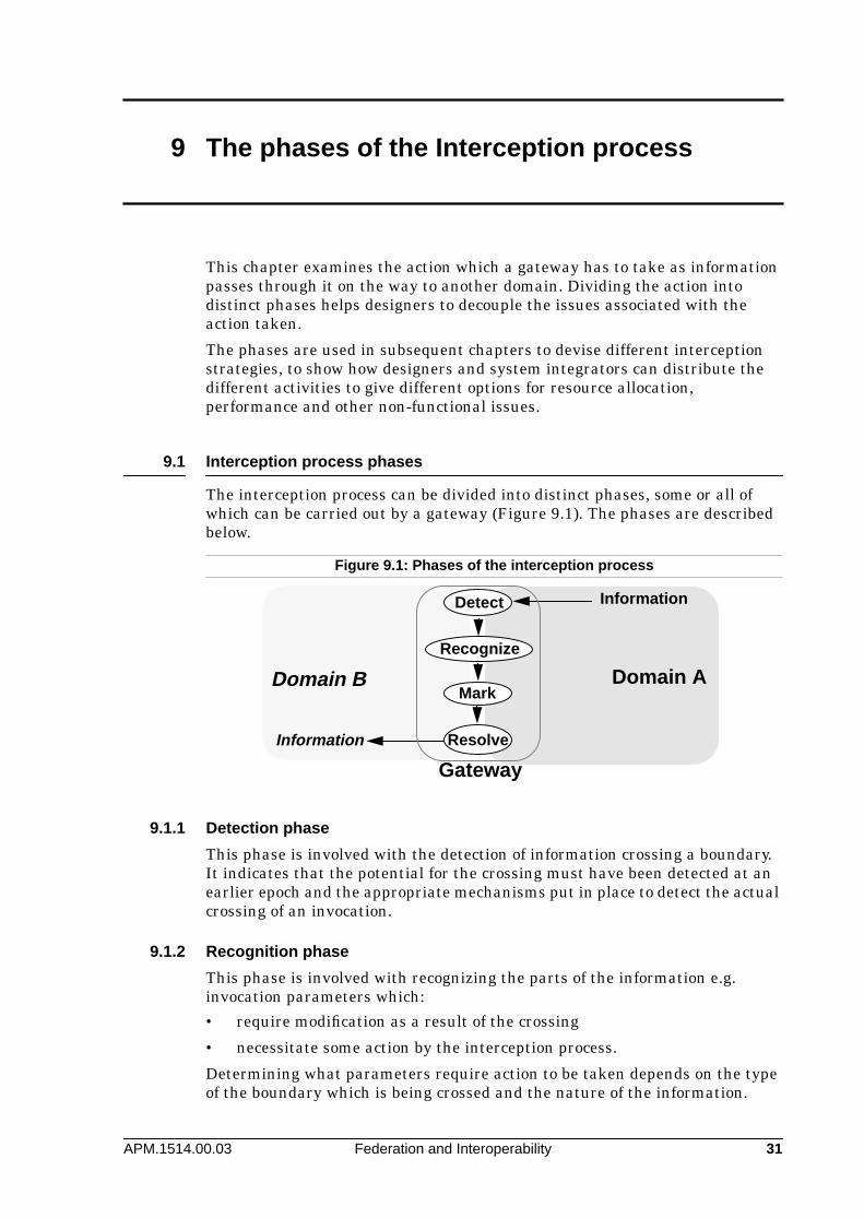
The interception process can be divided into distinct phases, some or all ofwhich can be carried out by a gateway (Figure 9.1). The phases are describedbelow.
9.1.1 Detection phase
This phase is involved with the detection of information crossing a boundary.It indicates that the potential for the crossing must have been detected at anearlier epoch and the appropriate mechanisms put in place to detect the actualcrossing of an invocation.
9.1.2 Recognition phase
This phase is involved with recognizing the parts of the information e.g.invocation parameters which:
• require modification as a result of the crossing
• necessitate some action by the interception process.
Determining what parameters require action to be taken depends on the typeof the boundary which is being crossed and the nature of the information.
Figure 9.1: Phases of the interception process
Information
Information
Domain B Domain A
Detect
Recognize
Mark
Resolve
Gateway

ANSA Phase III The phases of the Interception process
APM.1514.00.03 Federation and Interoperability 32
9.1.3 Marking phase
This phase is involved with the marking of information which needs actingupon by identifying what needs to be transformed and adding informationabout where or how this is to be done (Figure 9.2).
The different ways of marking can determine or at least constrain:
• which objects can request the resolution
• where the resolution will be carried out, and how and when
9.1.4 Resolution phase
This phase is involved with carrying out the necessary action required by thecrossing of a boundary. The resolution phase may be one or a combination ofthe steps shown in Figure 9.3 (some of these, but not all, are mutuallyexclusive):
• rejection of the crossing with or without notification to the source
• passing the invocation without changes
• transforming the content of the invocation
• creating any appropriate gateway (or gateways) in case of an interfacereference being passed
• monitoring: notifying some interested agent or recording the event.
For example, a rejection of a crossing is unlikely to be accompanied by thecreation of any gateways, whilst translation and creation of gateways do notnecessarily exclude each other.
Figure 9.2: The marking phase
Figure 9.3: Phases of the interception process
x, y,z+ Resolution-information
x, y, zDetect
Recognize
Mark
Detect Recognize Mark Resolve
Passas is
Transform Creategateway
Interception
MonitorReject
bouncedrop notify record

Interception resolution strategies ANSA Phase III
33 Federation and Interoperability APM.1514.00.03
10 Interception resolution strategies
The question of when translation occurs at domain boundaries affects variousnon-functional issues such as latency, throughput and the effectiveness ofresource allocation. For example, it is undesirable to translate informationthat is unlikely to be used. This chapter presents different strategies formanaging whether different activities are done, when, and by whom, anddiscusses their impact on the design of gateways and infrastructures.
Three resolution strategies are presented, which are based on different waysin which the marking and the resolution phase of the interception process canbe joined.
10.1 Immediate resolution strategy
Where the resolution process immediately follows the Detect/Recognize/Markphases of the interception process, the result is the Immediate Resolutionstrategy (Figure 10.1).
The resources required for the resolution process are allocated to it regardlessof whether the transformed information passing through the domainboundary will be used in Domain B or not. This is wasteful in cases where itwill not be used. The example of interface reference passing domainboundaries will be described in detail in Chapter 11.
One advantage of the immediate resolution strategy is that the informationpassed into Domain B will require no further transformations: these may betime consuming and cause initialisation delays at a later stage.
Another advantage of this strategy is that the infrastructure of Domain B andthe recipient object will require no changes as it will receive information in theform it is expecting. The entire transformation is carried out in the gatewayprior to the information crossing the boundary. This is important in legacysystems - where it is not possible to modify an application or an environment.
Figure 10.1: The Immediate resolution strategy
Detect
Recognize
Mark
Resolve
x, y, z
x, Ψ, z
Domain B Domain A
x, Resolve [ y], zResolution- info
(1)(2)
(3)
(4)(5)

ANSA Phase III Interception resolution strategies
APM.1514.00.03 Federation and Interoperability 34
10.2 Deferred resolution strategy
If the Detect/Recognize/Mark phases are separated from the Resolution phase,allowing an object in Domain B to decide if and when (and sometimes where)the resolution process will take place, the result is the Deferred Resolutionstrategy1 (Figure 10.2).
In step (4) the gateway’s marked information is forwarded to a recipient inDomain B. The recipient object (or any object it passes this information to) candecide to use the information (5) and request the resolution (6). This strategywill require a Resolver which can accept invocations from objects in domain B.
10.3 Leave-and-Forward resolution strategy
If information marked as deferred at a domain boundary, is sent by an objectin the recipient domain back to the sending domain (as an invocationparameter, for example), it may not be necessary to resolve the deferredmarking at all if at some later stage it is to be sent back to the originatingdomain without any changes2.
The Resolver in this case acts as a bounce-forward agent and has to be able torecognize the marked information and be able to strip the marking off,forwarding it to the domain from which it originated (Figure 10.3).
10.4 Choosing a resolution strategy
The decision as to whether to use the immediate, deferred or Leave-and-Forward resolution strategy will be dictated by the policy of the domainswhich the gateway spans, and the gateway management and maintenancepolicy. Choosing the deferred or leave-and-forward strategy will require therecipient domain to be capable of receiving marked information and dealing
1. This is similar to a situation where a tourist goes on holiday with home currencyand decides not to convert the money back until she needs it.
2. This is similar to a situation where a tourist decides not to convert her home moneyto the local currency because the person she has to pay plans to visit her countryshortly and will need money in that currency. Both gain from not having to convert thecurrency and pay commission.
Figure 10.2: The Deferred resolution strategy
Detect
Recognize
Mark
ResolverΨ
Domain B
Domain ADeferredresolutionrequest Resolve [y]
+ Resolution- info
X, Deferred [y] , Z+ Resolution- info
(1)(2)
(3)(4)
(5)
(6)
(7)(8)
x, y, z

Interception resolution strategies ANSA Phase III
35 Federation and Interoperability APM.1514.00.03
with it. This may not always be acceptable since it will either require a changein the interface definition of the client or an agreed way to mark information.
The resolver or forwarding agent may not necessarily reside in the gateway aslong as it is accessible from the recipient domain. It is also possible to have adefault resolver for one or more types of boundaries crossed, so that themarking does not necessarily have to include the reference to the resolver inthe marked information.
10.5 Level of resolution
There following are examples of the different places where resolution can berequested and carried out:
• a server or server manager: these can create a gateway for a service wherea boundary between incompatible applications is to be crossed
• a server binder: when creating the interface reference for a service thebinder can consult a domain manager and create a technical oradministrative gateway
• a trader: can detect a difference between the properties of a client andserver and act to create a gateway to perform the required conversion. InANSAware, for example, the trader acts as a gateway interceptor whichinserts a relocator interface reference into the server’s interface reference[ARM 93]
• a domain manager: can create a technical or administrative gateway oneither the client or the server side
• client or client manager: similarly to the server and server manager theclient side can create a gateway when it receives the server interfacereference
• client binder: when binding the client to a server in a different applicationdomain
Figure 10.3: The”Leave-and-Forward” resolution strategy
Detect
Recognize
Mark
Domain B
Domain A
(1)(2)
(3)
(4)(5)
(6)Op(Leave[y], args) Forward
gate
requestResolution
X, Leave [y], Z+ Resolution- info
x, y, z
Op(y, args)

ANSA Phase III Passing interface references through domain
APM.1514.00.03 Federation and Interoperability 36
11 Passing interface references through domainboundaries
This chapter illustrates the interception strategies described in §9 The phasesof the Interception process by showing how each strategy handles interfacereferences which are exchanged across domain boundaries. It aims to assistplatform designers and system integrators in determining the mostappropriate approach by highlighting the non-functional benefits of eachstrategy and the design implications for infrastructures.
11.1 Crossing domain boundaries
In order to describe what happens when interface references cross domainboundaries, the example of connecting two different distributed applicationplatforms is used. Most existing platforms (DCE [OSF 92], CORBA based [OMG92], ANSAware [ARM 93] for example), use different RPC mechanisms and alsodifferent notions of the information and structure of interface references (e.g.interface references in ANSAware, Binding handles in DCE and Objectpointers in CORBA). Both differences have to be accommodated by thegateways bridging the two domains.
Three strategies are illustrated:
• immediate resolution strategy
• deferred resolution strategy
• leave-and-Forward strategy
In the following figures, interface references are shown in a graphical manner.The exact nature of their structure and information will be discussed in detailin chapter 14.
11.2 Immediate resolution strategy and interface reference passing
The immediate resolution strategy shown in Figure 11.1 supports thecreation of the necessary gateway as the interface reference is passing theboundary.
11.2.1 The immediate resolution strategy sequence
The sequence of operations in the immediate resolution strategy (Figure 11.1)is:
1. the server interface reference is sent from the sender domain to therecipient domain but gets intercepted by the gateway
2. the gateway resolver, according to the immediate resolution strategy,requests a gateway factory to create an appropriate gateway, and passes itthe interface reference of the server in the sender domain

Passing interface references through domain boundaries ANSA Phase III
37 Federation and Interoperability APM.1514.00.03
3. the factory creates the requested gateway with its interface in therecipient domain. The new gateway can bind to the server at this point
4. the created gateway passes its interface reference to the factory5. the factory returns the gateway interface reference to the originating
gateway resolver and interceptor6. the new interface reference is passed to the client in the recipient domain7. the client passes the gateway interface reference to its Binder8. the binder creates and returns a local handle for the client9. the client performs invocations on the created gateway.
11.2.2 Advantages and disadvantages of the immediate resolution strategy
The main disadvantage of the immediate resolution strategy lies in the factthat resources are allocated for constructing the gateway regardless ofwhether the service will be used from the recipient domain.
The main advantage of the strategy is that once the resources are allocated tothe gateway, it is possible to guarantee that the gateway will be availablewhen necessary. Also, no additional time has to be spent in setting up thegateway when the binding is created. This may be important in real-timeapplications.
This strategy also has the advantage that it provides a way of dealing withlegacy systems as it does not require any changes to be made to the supportingplatforms or applications in order to deal with boundary crossing. To therecipient domain, the interface reference will appear as if it is supported by aservice in the same domain.
11.2.3 Requirements placed on distributed platform design
None.
Figure 11.1: immediate resolution strategy
Resolver
(1)
(6)
Factory
Client
(9)(2)
(3)(4)
(5)
Domain (protocol P1)
Domain (protocol P2)
Binder
(7) Bind(Ifref)(8)Localhandle
Ifref=
AW P1
AW P1
AW P1
AW P1
ORB P2
ORB P2
ORB P2
Gateway
Gateway
ANSAware
CORBA
ORBRes
ORB P2
Service
Interceptor
Gateway

ANSA Phase III Passing interface references through domain
APM.1514.00.03 Federation and Interoperability 38
11.3 Deferred resolution strategy and interface reference passing
The deferred resolution strategy (Figure 11.2) intercepts the passing of theinterface reference through the domain boundary. It then marks the interfacereference to indicate that it has crossed a domain boundary and that it willultimately require the creation of the appropriate gateway before being usedto invoke the server in the other domain. At some time before the invocationtakes place, the marked information will have to be passed to a gateway-resolver capable of creating the gateway.
The request to resolve the deferred interface reference can take place eitherwhen client requests the binder to set up the binding, or it can take place onfirst invocation attempt.
11.3.1 The deferred resolution strategy sequence
The sequence of operations in the deferred resolution strategy (Figure 11.2) is:
1. the server interface reference is sent from the sender domain to therecipient domain but gets intercepted by the gateway
2. the gateway interceptor, according to the deferred resolution strategy,marks the information as deferred (“defer”), adding the reference of thegateway resolver where the deferred interface reference can be resolvedwhen required. The marked interface reference is then passed to therecipient domain
3. the client requests Binder to bind to the interface using the passedinterface reference
4. the binder recognizes the interface record marked as deferred, extractsthe gateway resolver reference and sends the deferred interface record (orthe entire interface reference) to the gateway resolver
Figure 11.2: Deferred resolution strategy
Resolver
(1)
(2)
Factory
Client
(9)
(11)
(4)
(5)
(6)(7)
(8)
Domain
Domain (protocol P2)
Binder
(3) Bind(Ifref)(10)Localhandle
Ifref=
AW P1
AW P1
Defer AW P1 ORBRes P2
AW P1
AW P1
ORB P2
ORB P2
ORB P2
ORB P2
Gateway
ANSAware
CORBA
Defer AW P1
ORBRes
Service
Interceptor
(Protocol P1)
Gateway
Gateway
Passing interface references through domain boundaries ANSA Phase III
39 Federation and Interoperability APM.1514.00.03
5. the gateway resolver requests a gateway factory to create an appropriategateway, passing it the interface reference of the server
6. the factory creates the requested gateway with its interface in therecipient domain; the new gateway can bind to the server at this point
7. the created gateway passes its interface reference to the factory8. the factory returns the gateway interface reference to the gateway
resolver9. the new interface reference is passed to the Binder in the recipient domain10. the binder creates a binding to the gateway and returns a local handle for
the client11. the client performs an invocation on the created gateway.
11.3.2 Advantages and disadvantages of the deferred resolution strategy
The deferred resolution strategy is more efficient with regard to resourceutilization than the immediate resolution strategy as the creation of gatewaysonly takes place when a client requests their creation, i.e. when it wishes touse the service.
The main disadvantage of this strategy is that it places overheads on thecreation of the client-server binding in terms of the time taken to set up thegateway. Also this strategy requires changes to the supporting distributedplatform.
11.3.3 Requirements placed on distributed platform design
The interface reference has to be able to hold foreign interface referenceswithin it together with gateway-resolver references. The Binder has to be ableto extract and use this information to invoke the appropriate gateway-resolver.
11.4 Leave-and-Forward resolution strategy and interface reference passing
When an interface reference is passed through a domain boundary and ismarked as “Leave”, it is possible to have the marked interface reference usedfor invoking the service it is referring to, by passing it as one of the invocationparameters without having to resolve it. The gateway resolver can thenforward the invocation to the relevant service.
This however, will require a change in the interface definition of the client andthe gateway to include the interface reference as a parameter and is unlikelyto be acceptable. One possible implementation is to carry the destinationinterface reference in the RPC header so that the gateway resolver can obtainit and use it. This will not require a change in the interface definition andstubs but will require the RPC protocol and mechanisms to carry and dealwith the information as necessary. Implementation of the Leave-and-Forward strategy at the RPC level with use of the gateway-resolver as abounce-forward agent is shown in Figure 11.3.
The allocation of resources in this strategy leaves the following choice to thedesigner:
• a binding between the gateway and server can be established and heldover more than one invocation from the client. This implies the gateway-resolver holds client-server specific state

ANSA Phase III Passing interface references through domain
APM.1514.00.03 Federation and Interoperability 40
• a binding between the gateway and server can be established for eachinvocation and discarded after response is delivered to client.
11.4.1 The Leave-and-Forward strategy sequence
The sequence of operations in the Leave-and-Forward strategy (Figure 11.3)is:
1. the server interface reference is sent from the sender domain to therecipient domain but gets intercepted by the gateway
2. the gateway interceptor, according to the Leave-and-Forward strategy,marks the information as “leave”, adding the reference of the bounce-forward resolver where the invocations are to be sent to, and forwards it tothe client
3. the client passes its Binder the interface reference4. the binder returns a local handle for the bounce-forward resolver, having
set up the appropriate communications5. the client invokes the bounce-forward resolver passing it the interface
reference of the server as part of the RPC header information6. the bounce-forward resolver requests the binder in sender Domain to
create a binding to the service7. a local handle for the server is returned to the bounce-forward resolver8. the bounce-forward resolver forwards the invocation to the server.
11.4.2 Advantages and disadvantages of the Leave-and-Forward strategy
The main advantage of the Leave-and-Forward strategy is that it does notrequire holding any state in the gateway concerning bindings between clientsand servers. This will make re-starting such a gateway after failure easier asno mappings between clients and servers will be lost.
If the binding between the server and gateway is established and discarded onper invocation basis, the overheads of establishing a binding for eachinvocation will be prohibitive in some real-time applications.
Figure 11.3: The Leave-and-Forward strategy
ForwardResolver
(1)
(2)Client
(5)
Domain
Domain (protocol P3)
Binder
(3) Bind(Ifref)(4)Localhandle
AW P1
AW P1
Bounce
Gateway
ANSAware
CORBA
Service
Interceptor
Ifref= Leave AW P1 ORBRes P3
RPC packet
PayloadHdr(ORBRes)
Binder
(6) Bind(SIfref)(7)Localhandle
AW P1
(8)
(protocol P1)
Passing interface references through domain boundaries ANSA Phase III
41 Federation and Interoperability APM.1514.00.03
11.4.3 Requirements placed on distributed platform design
This method places requirements on distributed platform:
• a gateway interceptor must be able to mark an interface reference toindicate that the Leave-and-Forward strategy is to be used
• the binder has to be able to recognize the marking and act on itaccordingly
• an RPC protocol supported by the platform must carry the full interfacereference of the destination in an agreed part of its header
• the gateway bounce-forward resolver must support the same RPCprotocol.

ANSA Phase III Interception implementation issues
APM.1514.00.03 Federation and Interoperability 42
12 Interception implementation issues
The design of gateways determines the extent to which the non-functionalcharacteristics of links can be managed, and constrains the non-functionalcharacteristics of interactions occurring across those links.
This chapter discusses design options for gateways, discussing their impact onnon-functional issues and showing how they relate to the interception issuesintroduced in previous chapters. It then discusses issues for ordering andcombination of gateways and highlights potential problems.
12.1 Overview of design issues for interception and gateways
The computational model of interception shown in Figure 8.5 may beimplemented by creating a private gateway for each interface reference whichis passed through bindings across each domain boundary; each gateway mighthold all the information and resources it requires privately.
This may be unacceptable in engineering terms because of inefficient resourceusage and duplication of information. The computational gateway, generatedby a parent gateway, may be implemented differently, depending on theengineering decisions taken. The interception strategy adopted may impactthe design of both gateways and infrastructures.
A gateway can be viewed as:
1. information about the transformations that have to be applied at theboundary.
2. an interface for managing a set of bindings.
3. information enabling bindings to be set up and maintained (how to bind toservers; e.g. hold server interface references or the actual bindings).
4. the resources required to implement the appropriate interactions andtransformations.
A gateway can thus be implemented in a variety of ways and theimplementation options can be derived from the different possible answers tothe following inter-related questions:
1. how should the information describing transformations be distributed?
2. what sets of bindings can be managed by one gateway?
3. how should the information about bindings be distributed?
4. what resources are allocated, when, and for how long?
5. when many transformations are applied, how should they be ordered?
In practice, there is a spectrum of design options for the design of a gateway,and for the ways in which different gateways may be positioned and combined.

Interception implementation issues ANSA Phase III
43 Federation and Interoperability APM.1514.00.03
12.2 Choosing gateway design options
Which design options are most appropriate for any particular gateway will bedetermined by the following issues:
• Performance and QoS guarantees: early versus late allocation ofresources may affect trade-offs of latency versus throughput, andefficiency of resource usage versus latency. Consequently, it may constrainthe QoS guarantees which can be given, particularly with regard toavailability and performance
• Management of domain boundaries: boundaries may need to be madevisible for enterprise, administrative or technical reasons; as aconsequence, information exchanged between gateways may need to bemonitored in specific forms. It may be important to be able to trace theparenthood relationships of gateways for management, security or billingpurposes; this implies a need to make distinctions between differentclient-server bindings.
• Technical issues: for example, the availability of interface specific versustype generic stubs can have a significant effect on gateway design andimplementation (generic stub facilities such as CORBA DSI/DII [UNO 95]).Sharing of resources as in the case of type generic gateways may alsoaffect performance and influence the QoS guarantees. Availability ofmulti-threading together with performance requirements may dictateresource allocation issues.
• Application semantics: the specific requirements of the application mayplace constraints or indicate which option is most appropriate.Applications with extreme requirements may merit specific mechanisms.
12.3 Gateway design options
This section discusses the options for design of a single gateway. Furtherdetail concerning gateway design options can be found in [APM.1303 95].
12.3.1 Distribution of information about transformations
Information specifying which transformations should be applied at whichboundaries, to which types and values of information and under whichcircumstances, must be available to each gateway. Such information may bephysically held:
1. privately by each gateway.
2. shared between many gateways.
3. in shared repositories, but with some specific information held privately.
No matter whether information is shared or not, it must be organised in someway. Options are:
1. per-type: all information describing transformations that should beapplied to transform to or from particular type is held together.
2. per-boundary: all information describing transformations that should beapplied at a particular boundary is held together.
3. per-domain: all information describing transformations that should beapplied at all boundaries of a particular domain is held together.

ANSA Phase III Interception implementation issues
APM.1514.00.03 Federation and Interoperability 44
4. various combinations of the above.
In general, information should be shared wherever this does not compromisemaintainability or performance. Performance requirements may dictate thattransformations be represented as executable code, in which case sharing mayonly occur prior to compilation. If the shared information may alter for somebut not all of the parties sharing it, the sharing may be a maintainabilityproblem.
The per-domain option will usually be the first one to be applied, since it isusually desirable for domains to remain autonomous. Usually it is a questionof whether per-type information should be held on a per-boundary basis, orvice-versa. This depends upon where the greatest commonality is to be found,which in turn is dependant upon the nature of the differences, but in mostcases will be per-boundary.
More general gateways (e.g. type generic stubs) allow the use of a singleinterface to act as a gateway for different types of bindings, therebycircumventing the need to create more gateways as interface references ofdifferent service types cross the boundary and enabling more efficient resourceusage. However, during conditions of high load in a gateway which sharesresources between bindings, the creation and use of private resources may benecessary to maintain performance.
12.3.2 Distribution of bindings across gateways
There are various options for the allocation of bindings to gateway instances:
1. Multiple simultaneous clients and servers for each gateway instance.
2. Multiple simultaneous clients and one server for each gateway instance.
3. One client and multiple simultaneous servers for each gateway instance.
4. One client and one server at a time for each gateway instance.
Support for multiple simultaneous clients implies that some state aboutserver invocations is held, either in the invocation messages to servers or ingateways, to relate these invocations to clients, so that a response from aserver can be returned to the correct client.
If a single gateway instance manages multiple bindings, either with clients orservers, there is the question of which set of bindings are shared. This may beconstrained by the strategy selected for the distribution of information abouttransformations. For example, an instance of a type specific gateway may notmaintain bindings of different types.
This choice affects the granularity with which certain management policiescan be applied to different bindings. It may have security implications due topossible interactions between different bindings. Reliability, performance andefficiency of resource usage may be affected depending upon the assignment ofresources to gateways.
Further discussion of these issues can be found in [APM.1303 95].
12.3.3 Distribution of information about bindings
Information about bindings may be held entirely in a gateway, so there is noinformation about the server in the client invocation message.
Alternatively, some or all of the information about the servers nature andlocation may be held in the client invocation message (e.g. in an RPC header)

Interception implementation issues ANSA Phase III
45 Federation and Interoperability APM.1514.00.03
in which case the gateway acts as a router, processing and forwarding clientinvocation messages solely on the basis of the information contained in eachsingle invocation message. Note that the client infrastructure may obtain thisinformation via an interface reference for the server.
This is analogous to the distinction between connection-oriented andconnectionless protocols.
With the connection-oriented approach, the gateway must maintain a bindingconstantly until it is terminated, which means that the resources it requiresremain allocated. The connectionless approach allows the binding to bediscarded and re-created upon a later invocation, so resource allocation maybe managed in a more flexible manner.
12.3.4 Resource allocation
12.3.4.1 What resources are allocated to each binding?
Essentially, there are four different kinds of resource which may be sharedbetween bindings:
• capsules, or in other words address spaces
• threads
• interfaces
• implementations; sharing of implementations between bindings occurswhen interactions across different bindings are processed using the sameexecutable code.
Sharing in each of these aspects may be altered independently of the others.
12.3.4.2 When are resources allocated to bindings?
The allocation of resources to bindings can happen at different points:
• immediate resolution strategy: there is immediate allocation of resourcesto create gateways when an interface reference crosses a domainboundary
• deferred resolution strategy: this involves deferring gateway creation to
— any object which recognizes the deferment of the resolution andknows how to extract the information necessary to request theresolution
— first invocation only, with the gateway remaining in place, orinitialisation on every invocation
• leave-and-forward strategy: this may result in no permanent allocation ofresources for a client-server binding if used on a per invocation basis
12.3.4.3 For how long are resources allocated to bindings?
The resources required for a binding may be maintained for various differentdurations:
• a single invocation
• one session with one client; the end of the session must be indicated bysome means
• all sessions with a client, in which case the client must signal its demiseor intent not to interact with the server again

ANSA Phase III Interception implementation issues
APM.1514.00.03 Federation and Interoperability 46
Where information about bindings is held in the gateway rather than in serverinvocation message (see 12.3.3), it is usually preferable to maintain a singlebinding for the duration of a session.
Where the server holds state, it may be necessary to maintain a client-serverbinding for the lifetime of a client.
12.3.5 Ordering of composite gateways
Objects belong to several domains of different types, so multipletransformations are likely to be needed when they interact with other objects(Figure 12.1). It is usually inefficient to implement successive transformationsusing different gateways, so transformations are usually collocated inside asingle gateway. Care should be taken:
• to retain low coupling between transformations
• to order the transformations in such a way that they will not adverselyeffect the transformations or prevent them from being carried out.
The order in which transformations are applied places constraints on theaccessibility of the information, and there are often performance issues. Theseare discussed below.
Two examples of the ordering of unmarshalling and marshalling with respectto other transformations are given below as an illustration. RPC stubs are awell-understood form of gateway.
12.3.5.1 Marshalling and unmarshalling first
Gateways may be implemented as stand-alone and therefore potentiallyremote from clients and servers; this may be useful where for legacy reasonsthe client and/or server cannot be modified (Figure 12.2). This implies thatmarshalling and unmarshalling must occur before other transformations.
Figure 12.1: Clients and servers in a multiple domain environment
Figure 12.2: Distributed stand-alone gateway implementation
DomainManager
Domain Type1 Domain Type1
Transform TransformClient Server
DomainManager
Domain Type2
Transform
DomainManager
Transform
DomainManager
Domain Type 3
Transform
IDomainManager
Transform
IDomainManager
Domain Type 2Domain Type 3
Server
Protocolstack Platform YPlatform X
TransformationTransformation Client
RPCx RPCy
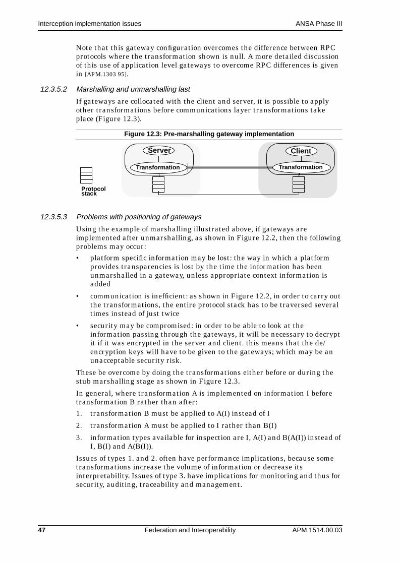
Interception implementation issues ANSA Phase III
47 Federation and Interoperability APM.1514.00.03
Note that this gateway configuration overcomes the difference between RPCprotocols where the transformation shown is null. A more detailed discussionof this use of application level gateways to overcome RPC differences is givenin [APM.1303 95].
12.3.5.2 Marshalling and unmarshalling last
If gateways are collocated with the client and server, it is possible to applyother transformations before communications layer transformations takeplace (Figure 12.3).
12.3.5.3 Problems with positioning of gateways
Using the example of marshalling illustrated above, if gateways areimplemented after unmarshalling, as shown in Figure 12.2, then the followingproblems may occur:
• platform specific information may be lost: the way in which a platformprovides transparencies is lost by the time the information has beenunmarshalled in a gateway, unless appropriate context information isadded
• communication is inefficient: as shown in Figure 12.2, in order to carry outthe transformations, the entire protocol stack has to be traversed severaltimes instead of just twice
• security may be compromised: in order to be able to look at theinformation passing through the gateways, it will be necessary to decryptit if it was encrypted in the server and client. this means that the de/encryption keys will have to be given to the gateways; which may be anunacceptable security risk.
These be overcome by doing the transformations either before or during thestub marshalling stage as shown in Figure 12.3.
In general, where transformation A is implemented on information I beforetransformation B rather than after:
1. transformation B must be applied to A(I) instead of I
2. transformation A must be applied to I rather than B(I)
3. information types available for inspection are I, A(I) and B(A(I)) instead ofI, B(I) and A(B(I)).
Issues of types 1. and 2. often have performance implications, because sometransformations increase the volume of information or decrease itsinterpretability. Issues of type 3. have implications for monitoring and thus forsecurity, auditing, traceability and management.
Figure 12.3: Pre-marshalling gateway implementation
ClientServer
Protocolstack
Transformation Transformation

ANSA Phase III Interception implementation issues
APM.1514.00.03 Federation and Interoperability 48
12.4 Impact of design choices on infrastructures
Many of the issues described above only affect the design of the gatewaysthemselves, and the non-functional characteristics of gateways.
However, some of the issues may affect the design of the client and serverinfrastructures, and these should be given special attention.
• Deferred resolution: implies that the server infrastructure must be able totransport foreign binding information, and recognise markings indicatingforeign information, and be able to pass foreign information to designatedresolvers.
• Binding information in invocation message: implies that the clientinfrastructure must be able to hold binding information in invocationmessages. This binding information must enable a binding to a foreignobject, so either the foreign information itself must be included directly, ora complete translation of the foreign information must be used.

APM.1514.00.03 Federation and Interoperability 49
13 Binding
In order to support different interception options, some enhancements toinfrastructures may be required. In particular, the resolution process chosenwill influence the design of resolvers. Binders resolve interface references intolocal handles, and are thus affected by different interception strategies in thesame way as any other kind of resolver.
The impact of the interception strategies on the design of binders is consideredin this chapter, as an illustration of the influence on resolvers in general. Theinformation which is resolved may also be affected, and the relationshipbetween binders and interface references demonstrates this.
13.1 Binding and interface references
Since interface references may be nested, and are likely to be exchangedwidely and frequently, it may be appropriate to modify the internal structureof interface references to support the interception options efficiently (§14Interface references and interception). The binding process must support suchmodifications:
• recognise interface records nested within interface records
• recognise interface records marked as deferred or leave-as-is
• recognise relocation information
• extract information about where to resolve the marked information, i.e.the gateway resolver (or use a default gateway-resolver) in the case ofdeferred resolution
• extract information about where to send the forwarded invocation in thecase of the leave-as-is strategy
• allow for other information concerning issues such as relocation, andpassivation and activation.
13.2 Binder policy
As the order of interface records is not necessarily indicative of preferences orpriorities of either the producer or the consumer of the interface reference, thebinder’s policy has to determine:
• whether to deal with each record at a time or adopt some other approachsuch as searching for immediately usable references before trying toresolve marked ones
• under what circumstances to look for short cuts in invocation pathsdescribed by marked interface records (this will be discussed in Chapter14).

ANSA Phase III Binding
APM.1514.00.03 Federation and Interoperability 50
13.3 Binder algorithm
In order to construct a binding using an interface reference, a binder has to:
1. determine what order in which to try the available interface recordsaccording to dictated policy
2. process each interface record in order:
— immediately usable records: set up communications resources andpass the client a local handle to invoke
— records marked as deferred: extract the resolver interface referenceand use it pass the interface reference which is currently beingprocessed to the resolver. The returned interface reference isprocessed from the beginning; it too may be marked
— records marked as leave-as-is: extract resolver interface reference andset up the appropriate communications resources and RPC with thedestination interface reference in the RPC header, and pass the clienta local handle to invoke.

APM.1514.00.03 Federation and Interoperability 51
14 Interface references and interception
Interface references are crucial for co-operation between systems, because theexchange of interface references is a pre-requisite for interaction betweenthem.
In accord with §13 Binding, this chapter considers the requirements whichinteroperability places on interface references. For interface references whichare to be exchanged between different systems, there are a range of otherdesirable requirements which are also identified. These characteristics are ofgreat importance for platform designers.
14.1 Introduction
An interface reference contains the engineering information needed toestablish a remote connection between a client object and a server object or setof server objects [ARM 93]. Note that it is not a capability: the service maydecline to respond to invocations, for example for security reasons.
This chapter describes the kinds of information that must be present in aninterface reference and how it is used in establishing and maintaining aconnection.
An interface reference may contain information that:
1. names, in the context of the client’s binding manager, the end-point towhich requests should be sent.
2. identifies alternative routes for reaching the same end-point.
3. enables integrity checking of end-to-end bindings against errors intransparency and network management mechanisms.
4. supports transparent migration of the interface which it refers to.
5. supports transparent replication of the interface which it refers to.
6. supports different interception strategies.
7. enables heterogeneous interface references to be exchanged betweendifferent DPEs.
The requirements which should be met for each of these aspects are discussedin three different categories:
• minimal requirements, which any interface reference must meet
• requirements for interoperability, which any interface reference shouldmeet if it is to be exchanged between different systems. This suggests astructure for interoperable interface references (see §14.4 Recommendedinterface reference structure).
• requirements to support other transparencies; whilst these are notdirectly associated with interoperability, they may affect and be affectedby the interoperability strategy adopted.

ANSA Phase III Interface references and interception
APM.1514.00.03 Federation and Interoperability 52
14.2 Minimal requirements for interface references
14.2.1 End-point Naming
This is the only mandatory function of an interface reference. Interfacereferences name end-points which represent destinations for messages. Thenature of the end-point is not constrained; for example it might be:
• a network port, which might be named by a protocol name and a portname. Here, the protocol name also implicitly identifies a naming context
• an instance of an interface, which might be named by a node name, acapsule name and an interface name. Here, the node name might alsoimplicitly identify a naming context.
Different processing environments should be free to employ differentstrategies for naming end-points. The only general requirement is that thenaming scheme employed should be completely context relative.
This gives an evolutionary approach to systems integration and makes itpossible to combine new applications with existing applications (legacysystems) and to enable interworking over a range of distributed systemsplatforms.
14.3 Interoperability requirements on interface references
Interoperability places the following requirements on interface references:
• Accommodating alternative routes
• Accommodating different interception strategies
• Manipulating and passing interface references.
14.3.1 Accommodating alternative routes
The interface to which an interface reference enables access may be reachedvia many different routes. These routes may be different in that:
• They allow the interface to be invoked via different protocols.
• They allow the interface to be invoked via a different sequence ofintermediate interfaces, such as proxies, interceptors and gateways.
An interface reference may have one or more interface records, each providinginformation about possible paths between the client and server (Figure 14.1).
Routes involving proxies, interceptors and gateways are discussed insubsequent subsections.
Binders will be able to choose whichever option best matches the availablecomms infrastructure, QoS constraints and cost in terms of resources.
Figure 14.1: Interface Reference structure - one or more alternative paths
AW Px1 (1) Single option
AW Px3 ORB Py (2) Alternative optionsDCE Pz

Interface references and interception ANSA Phase III
53 Federation and Interoperability APM.1514.00.03
14.3.2 Accommodating different interception strategies
The deferred resolution and leave-as-is approaches are discussed in §10Interception resolution strategies.
14.3.2.1 Deferred resolution strategy
Where the deferred resolution method is used, the information about thecascade of gateways can be represented in a nested fashion with the referenceto the gateway-resolver appended.
The label “defer” tells the Binder that the marked information is not to beinterpreted by the Binder directly but passed to the resolver (whose referenceis appended to the marked information) to be resolved.
14.3.2.2 Leave-and-Forward strategy
Where the leave-and-forward method is used, the information is marked withthe “leave” label. This tells the Binder that it should be used in the RPCheader of the invocation sent to the gateway resolver whose reference isappended to the marked information.
The gateway in this case could be a type generic gateway implemented so thatit receives the destination of the invocation from the RPC header and passesthe invocation on.
14.3.2.3 Short cuts and optimisations
When using the deferred resolution method, a Binder can try and skipgateway nesting of interface references and go directly to the service, providedof course that it has access to suitable communication protocols. There aretherefore two cases to consider:
• where the nested records are NOT options, binders must not try to skip agateway and bind directly to an interface nested inside the structure
• where short cuts can be made, binders may be permitted to take a moredirect route (e.g. to prevent circularity of reference), but sometimes thenon-functional characteristics of a longer route may be desired.
Whether the nesting indicates a compulsory path or not depends on the type ofboundary crossed and the enterprise or management issues associated withthe crossing of the boundary. Either way it should be left to the gateway-resolver to decide.
The information marked as deferred can also be encrypted so as to prevent itsresolution by unauthorised agents. This can help prevent taking any short-cuts where it is necessary to force the use of a gateway.
Figure 14.2: Deferred resolution information inside an Interface Reference
Figure 14.3: Leave-as-is information inside an Interface Reference
defer AW Px12 DCERes Pz Deferred option (single nesting)
leave AW Px12 ORBRes Py Leave-as-is option

ANSA Phase III Interface references and interception
APM.1514.00.03 Federation and Interoperability 54
14.3.3 Manipulating and passing interface references
Interoperability requires the ability to manipulate interface references andhence some agreement on structure and content of interface references isnecessary.
Different processing environments have adopted different kinds of interfacereferences, and this seems likely to continue. Support for interoperabilitymust therefore include the ability for platforms to manipulate, or at least toexchange, foreign interface references.
This can be achieved by allowing interface records and interface references ofdifferent types to be nested in a single interface reference, which acts as aninteroperable wrapper. Each specific wrapped interface record or interfacereference is prepended with a platform flag (e.g. “ANSAware RT” or “OODCE”), a version and a length, which allows it to be ignored efficiently byinfrastructures that do not understand it.
Labels for marking interception options, such as “deferred” and “leave”, arewrapped along with the interface records or references which they mark, sothere is no need for these to be globally agreed.
14.4 Recommended interface reference structure
The OMG has defined an interoperable wrapper of the kind described above,called the interoperable object reference (IOR) [UNO 95]. Figure §14.4 is apictorial representation of this, and partial IDL is given in Figure 14.5.
Figure 14.4: Interoperable Object Reference (IOR)
type_id:string
TaggedProfile
tag : unsigned long
length :unsigned long
Octet
IOR
Profile_data
length : unsigned long
Profiles
TaggedProfile
tag : unsigned long
length :unsigned long
Profile_data
Octet Octet Octet

Interface references and interception ANSA Phase III
55 Federation and Interoperability APM.1514.00.03
Figure 14.5: IDL for IOR structure
14.4.1 Tagged Profile
The TaggedProfile structure leaves the contents of profile_data unconstrained.The profile_data should hold sufficient information to enable interaction withsome object, but this may vary from a complete interface reference tosomething much more lightweight, e.g. a protocol identifier and an address.
The tag should identify the type of the profile, e.g. ‘CORBA/IIOP’ or‘ANSAware’.
Tag administration should be handled with care. To minimise the overheads oftag allocation, the tag may be divided into:
• tag-foundary field
• tag-family field.
This avoids the need for a single foundary for handing out tags: each foundary,identified by a unique value for the tag-foundary field, is assigned its ownsubset of the tag space which is called a tag-family, and it may then allocate itsreserved space autonomously, without the possibility of contention.Foundaries may be arranged hierarchically if required.
The profile_data includes the length of the profile_data in bytes, whichimproves efficiency by allowing infrastructures to skip profile_data for recordsof encoding types which are not understood. It should also include any otherinformation about the wrapped record(s) which is required by specificplatforms, such as version numbers or flags to indicate whether the recordsare for resolvers or gateways.
14.4.2 IOR
This is simply a sequence of TaggedProfiles, which will of course include thelength of the sequence.
Profiles in a single IOR may hold information describing several interfaces, inarbitrary forms; this allows free interchange of interface references betweenDPEs.
The type_id in the IOR may prove problematic if used incorrectly. It is notthought practical to standardise names for types globally, so great care mustbe taken to identify types using context relative naming at least, to ensurethat type names are not misinterpreted. This might be achieved by:
module IOR {typedef unsigned long ProfileId;
struct TaggedProfile {ProfileId tag;sequence<octet> profile_data;
};
struct IOR {string type_idsequence <TaggedProfile> profiles;
};};

ANSA Phase III Interface references and interception
APM.1514.00.03 Federation and Interoperability 56
• prepending the type name with a repository name where the interfacereference passed outside the assumed scope of the original repository
• identifying the type using an interface record for a type object in arepository; this could then be resolved into a gateway at a domainboundary if required.
Type names not treated in this fashion should be held in profile_data, as theyare effectively type domain specific.
14.5 Additional requirements on interface references
These requirements, whilst not directly concerned with interoperability, areoften desired. The solutions used for these requirements may constrain or beconstrained by solutions to interoperability requirements, but detailedanalysis of the issues has not yet been conducted.
14.5.1 Migration and Relocation
Migration or failure of the server invalidates interface references whichreferred to it. Interface references can include information that can be used forboth detecting the change in location and relocating the interface. This can berepresented as a sequence of interface references in increasing order of scopemarked accordingly (Figure 14.6).
When an invocation fails, the client infrastructure can request the Binder tointervene. The Binder then searches the interface reference either for analternative path (in case of comms failure) or for a resolver interface reference(in case the server relocated). The Binder then invokes the Resolver/Relocatorgiving it the interface reference. If successful, the Resolver/Relocator willreturn a new interface reference of the relocated service.
14.5.2 Integrity checking
An interface reference contains a nonce that can be used to perform an end-to-end check.
When a request arrives at a server, it is necessary for the server to check thatthe request arose from the use of an interface reference that was generated bythe server, and not by the interface reference of another server. This isnecessary because where servers are mobile, the location of a server offers noguarantee about the kind of service or the service instance that is provided.The end-to-end check is performed using the nonce, in the context of theconnection that has been established with the help of the address and protocolinformation.
The server will refuse to establish a connection with a client that cannot quotethe nonce for the interface being connected. These failures should be reportedto system management since they are indicative of a configuration error in thesystem. Since nonces are random and generated locally by each DPE theyprovide an overall statistical integrity check, not an absolute guarantee.
Figure 14.6: Relocation information in Interface Reference
AW Pr-T3 AWRes Pr-T1 relocator references (AWRes)AWRes Pr-T2

Interface references and interception ANSA Phase III
57 Federation and Interoperability APM.1514.00.03
Under no circumstances should the nonce be used as part of any nameresolution process.
14.5.3 Replication
The structure of the interface reference should accommodate the possibility ofa service being offered by a group [APM.1002 93].
Where a service is transparently provided by a group of servers, perhaps toincrease dependability for instance, the interface reference should appear as ifa single server is involved from the client application point of view, but containall the information required to allow the orderly progression of groupexecution protocols by the client ORB.
This can be achieved by allowing each interface record to hold a list of lists ofend-points, one list for each member of the group. The size of the group (itscardinality) is held, along with a count of how many times the membership ofthe group has changed (its incarnation). There is only one nonce for the group.
The number of replies expected to each request is the cardinality, but thenumber of requests to be sent may be less than the number of recipients,because some of the recipient addresses may be multi-cast.
The relationship between replication and iterception is beyond the scope ofthis paper.

APM.1514.00.03 Federation and Interoperability 58
References
[APM.1002 93]
Oskiewicz, E. & Edwards, N. “A Model for Interface Groups”, APM.1002, APMLtd, Poseidon House, Castle Park, Cambridge CB3 0RD U.K., February 1993.
[APM.1003 93]
van der Linden, R., “The ANSA Naming Model”, APM.1003, APM Ltd, PoseidonHouse, Castle Park, Cambridge CB3 0RD U.K., February 1993.
[APM.1005 93]
Deschrevel, J-P., “The ANSA Model for Trading and Federation”, APM.1005,Architecture Projects Management, APM Ltd., Poseidon House, Castle Park,Cambridge CB3 0RD U.K., 1993.
[APM.1021 93]
Herbert, A.J., “ORB Interoperability”, APM.1021, Architecture ProjectsManagement, Poseidon House, Castle Park, Cambridge CB3 0RD U.K., 1993.
[APM.1303 95]
Crawford, B., “Gateway Design and Implementation”, APM.1303, APM Ltd.,Poseidon House, Castle Park, Cambridge CB3 0RD U.K., 1995.
[APM.1387 94]
Hoffner, Y. “A Designers’ Introduction to Trading”, APM.1387, APM Ltd.,Poseidon House, Castle Park, Cambridge CB3 0RD U.K., 1994.
[APM.1392 95]
Otway, D. J., “The ANSA Binding Model”, APM.1392, APM Ltd., PoseidonHouse, Castle Park, Cambridge CB3 0RD U.K., 1995
[APM.1404 95]
Hoffner, Y. & Crawford, B., “Federation Work Plan”, APM.1404, APM Ltd.,Poseidon House, Castle Park, Cambridge CB3 0RD U.K., 1995.
[APM.1427 95]
Hoffner, Y. “The ANSA Interception Model”, APM.1427, APM Ltd., PoseidonHouse, Castle Park, Cambridge CB3 0RD U.K., 1995.
[APM.1446 95]
Hoffner, Y., “Using the Interception Model to Describe Architectural Issues”,APM.1446, APM Ltd., Poseidon House, Castle Park, Cambridge CB3 0RDU.K., 1995.
[APM.1507 95]
Hoffner, Y., “Interoperability and Distributed Platform Design”, APM.1507,APM Ltd., Poseidon House, Castle Park, Cambridge CB3 0RD U.K., 1995.

References ANSA Phase III
59 Federation and Interoperability APM.1514.00.03
[ARM 93]
“The ANSAware 4.1 manual set”, Architecture Projects Management, PoseidonHouse, Castle Park, Cambridge CB3 0RD U.K., 1993.
[BATESON 79]
Bateson, G., “Mind and Nature: a Necessary Unity”, Bantam Books, ISBN 0-553-34575-3, 1979.
[BULL 93]
Bull J. A., Gong L. & Sollins K. R., “Towards Security in an Open SystemsFederation”, European Symposium for Research in Computer Security -ESORICS ’92. Springer Verlag Lecture Notes in Computer Science, pp 2 - 20.ISBNs 3-540-56246-X, 0-387-56246-X
[HAMMER & CHAMPY 93]
Hammer, M. & Champy, J. “Reengineering the corporation”, HarperCollinsPublishers, Inc., ISBN 0-88730-640-3, 1993.
[IONA 93]
Orbix: Programmer’s Guide, Iona Technologies Ltd., Dublin, Republic ofIreland, 1993.
[ODP 93]
“Open Distributed Processing Reference Model”, ISO/IEC 10476, ITU-TReccomendation X.900 (1995) Parts 1, 2, 3.
[OMG 92]
“The Common Object Request Broker: Architecture and Specification”,Document Number 91.12.1, Object Management Group and X/Open, 1992.
[OSF 92]
OSF, “DCE Application Development Guide”, Open Software Foundation, 11Cambridge Centre, Cambridge, MA 02142, USA, 1992.
[SALTZER 84]
Saltzer J. H., Reed D. P. & Clark D., “End-To-End Arguments in SystemDesign”, ACM Transactions on Computer Systems, Vol. 2, No. 4, November1984, pp. 277-288.
[UNO 95]
“CORBA 2.0/Interoperability - Universal Networked Objects”, BNR EuropeLtd., Digital Equipment Corporation, Expersoft Corporation, Hewlett PackardCorporation, IBM Corporation, ICL, plc., IONA Technologies, Sunsoft Inc.,OMG Document number 95.3.10, March 20, 1995.