feet sp2016-013- care now t a t e 3 0 05 12 i n t e r ... cases/2016...10'txu esmt horizon...
TRANSCRIPT

HORIZONINTERSTATE 30
PINNACLE
INTERSTATE 30
INTERSTATE 30
C
PD-32
SP2016-013- CARE NOWSITE PLAN - LOCATION MAP =
The City of Rockwall GIS maps are continually under developmentand therefore subject to change without notice. While we endeavor
to provide timely and accurate information, we make noguarantees. The City of Rockwall makes no warranty, express
or implied, including warranties of merchantability and fitness for aparticular purpose. Use of the information is the sole responsibility of
the user.
City of Rockwall
0 50 100 150 20025Feet
Planning & Zoning Department385 S. Goliad StreetRockwall, Texas 75032(P): (972) 771-7745(W): www.rockwall.com I

5
5
5
5
5
2
5
5
3
5
5
4
5
5
6
5
5
0
5
4
9
5
5
1
5
5
1
5
6
0
556
5
5
7
558
559
5
6
0
5
5
7
5
5
8
5
5
9
5
6
1
550
5
4
7
5
4
8
549
5
5
1
545
550
546
547
548
549
OWNER:
PARCEL ID NO. 66428
J BR2 LLC
VOL 6916, PG. 313
D.R.R.C.T.
LOT 1, BLOCK A
CHRISTIAN CHURCH SUBDIVISION
CAB A, PG. 213
P.R.R.C.T.
OWNER:
PARCEL ID NO. 51180
BRISCO OIL INC.
VOL 0995, PG. 254
D.R.R.C.T.
LOT 1, BLOCK A
BRISCOE/HILLCREST ADDITION
CAB D, PG. 245
P.R.R.C.T.
OWNER:
PARCEL ID NO. 51181
BRISCO OIL INC.
VOL 0877, PG. 221
D.R.R.C.T.
LOT 2, BLOCK A
BRISCOE/HILLCREST ADDITION
CAB D, PG. 245
P.R.R.C.T.
OWNER:
PARCEL ID NO. 86823
J BR2 LLC
DOC NO. 2015-0000016428
D.R.R.C.T.
LOT 2, BLOCK A
HARBOR DISTRICT ADDITION
DOC NO. 20140000003301
P.R.R.C.T.
OWNER:
PARCEL ID NO. 19920
ETHEL REED MOTON
VOL 0979, PG. 245
D.R.R.C.T.
LOT 1, BLOCK 1
GEORGE MORTON ESTATES
CAB A, PG. 47
P.R.R.C.T.
OWNER:
PARCEL ID NO. 19921
ALVIN D. SR. & ETHEL MOTON
VOL 0940, PG. 196
D.R.R.C.T.
LOT 2, BLOCK 1
GEORGE MORTON ESTATES
CAB A, PG. 47
P.R.R.C.T.
OWNER:
PARCEL ID NO. 19925
SPATEX JV - CULPEPPER
D.R.R.C.T.
LOT 1, BLOCK 2
GEORGE MORTON ESTATES
CAB A, PG. 47
P.R.R.C.T.
OWNER:
PARCEL ID NO. 19925
SPATEX JV - CULPEPPER
D.R.R.C.T.
LOT 2, BLOCK 2
GEORGE MORTON ESTATES
CAB A, PG. 47
P.R.R.C.T.
GRAVEL
OWNER:
PARCEL ID NO. 53842
(CALLED 0.18 ACRE)
THOMAS R. & JENNIFER BRISCOE
VOL 1921, PG. 102
D.R.R.C.T.
OWNER:
REMAINDER OF
CITY OF ROCKWALL
VOL 4324, PG. 290
D.R.R.C.T.
2
5
' B
.L
.
3
5
'
R
.
O
.
W
D
E
D
I
C
A
T
I
O
N
5
.
1
8
'
S
L
O
P
E
E
S
M
T
2
5
'
B
.
L
.
2
2
' P
U
B
L
IC
A
C
C
E
S
S
E
S
M
T
T
O
B
E
A
B
A
N
D
O
N
E
D
1
0
'
T
X
U
E
S
M
T
1
0
'
T
X
U
E
S
M
T
H
O
R
I
Z
O
N
D
R
I
V
E
(
V
A
R
I
A
B
L
E
W
I
D
T
H
R
.
O
.
W
.
)
(
C
O
N
C
R
E
T
E
P
A
V
E
M
E
N
T
)
I
N
T
E
R
S
T
A
T
E
H
I
G
H
W
A
Y
3
0
(
V
A
R
I
A
B
L
E
W
I
D
T
H
R
.
O
.
W
.
)
(
C
O
N
C
R
E
T
E
P
A
V
E
M
E
N
T
)
EXISTING
ALLEGIANCE TITLE ROCKWALL
EXISTING
PARKING GARAGE
FUTURE
PARKING
ADDITION
P
I
N
N
A
C
L
E
W
A
Y
D
R
I
V
E
(
9
0
'
W
I
D
T
H
R
.
O
.
W
.
)
PROPOSED CARENOW
5,550 SF
FFE = 552.20
1
8
'
2
4
'
1
8
'
3
'
1
8
'
2
4
'
3
'
9
'
T
Y
P
9
'
T
Y
P
2
4
'
P
R
O
P
.
A
C
C
E
S
S
D
R
I
V
E
R
3
8
'
R
3
8
'
R
5
'
EXISTING
CONC. PVMT
EXISTING
24 HOUR FITNESS
±
3
4
3
.
6
9
'
±
3
7
4
.
5
4
'
T
O
S
U
M
M
E
R
L
E
E
D
R
.
E
D
G
E
O
F
P
A
V
E
M
E
N
T
EXISTING DRIVE TO
BE REMOVED
2
'
5
'
S
I
D
E
W
A
L
K
N
4
6
°
2
6
'
0
8
"
W
1
8
1
.
6
5
'
N44°12'38"E
22.44'
N82°59'28"E
20.68'
S
7
6
°
0
3
'2
8
"
E
1
8
8
.6
2
'
S45°31'16"E
144.59'
N
4
5
°
3
1
'
4
8
"
W
1
5
8
.
5
5
'
N41°27'59"E
50.07'
N44°05'58"E
5.13'
1
0
'
L
A
N
D
S
C
A
P
E
B
U
F
F
E
R
N
4
4
°
1
2
'
4
4
"
E
1
4
1
.
4
7
'
8
'
1
2
'
1
2
'
8
.
5
'
3
.
5
'
5
'
5
'
B
.
L
.
4
4
'
9
'
9
'
9
'
9
'
9
'
9
'
5
'
5
'
R
2
0
'
R
1
0
'
R20'
R20'
R20'
R30'
R
30'
R
2
0
'
7
8
.
7
1
'
5
'
3
.
5
'
8
6
'
8
9
'
2
4
'
F
I
R
E
L
A
N
E
2
4
'
R10'
4
4
'
R
.
O
.
W
.
D
E
D
I
C
A
T
I
O
N
1
6
'
1
7
'
1
0
.
6
8
'
2
4
'
1
8
'
1
0
.
7
6
'
5
5
.
0
2
'
7
0
.
2
2
'
4
8
.
4
7
'
4
2
.
1
'
1
2
2
2
2
3
3
4
TYP.
5
5
5
5
6
6
6
7
8
9
TYP.
8
8
8
10
7
8
.
6
5
'
EXIST. 2-6" PIPES
ABOVE GROUND
EXIST. OVERHEAD
POWER LINE TO BE
RELOCATED
EXIST. POWER POLE
TO BE RELOCATED
EXIST. FH
EXIST. FH
EXIST. SSWR MH
EXIST. STORM MH
4'-5' RETAINING WALL
4'-5' RETAINING
WALL
EX.HILL TOP LANE
R.O.W. TO BE
ABONDONED
F.D.C.
EXIST. POWER
POLE
PROP. FH
PROP. WATER LINE
PROP. SEWER LINE
EXTENSION
7'-8' RETAINING WALL
W/ GUARD RAIL
2
0
'
B
.
L
.
3
2
.
1
9
'
R
1
0
'
PINNACLE WAY
DRIVE
(44' WIDTH R.O.W.)
EX. ROAD CL
EX. ROAD CL
PROP. ROAD CL
EX. ROAD CL
PROP. MONUMENT SIGN
(NOT TO EXCEED 9' AFF
AND 60 SF)
DA
TE
No
.R
EV
IS
IO
NB
Y
DATE:
SHEET
File No. 2016-029
05/12/2016
CHECKED: CLC
DRAWN: JEV
DESIGN: JEV
CA
RE
NO
WL
OT
1 &
2, B
LO
CK
AB
RIS
CO
E/H
ILC
RE
ST
AD
DIT
ION
RO
CK
WA
LL
, TX
19
03
C
EN
TR
AL
D
R. S
UIT
E #
40
6P
HO
NE
: 8
17
.2
81
.0
57
2
BE
DF
OR
D, T
X 7
60
21
W
WW
.C
LA
YM
OO
RE
EN
G.C
OM
TEXAS REGISTRATION #14199
P R E L I M I N A R Y
CLAYMOORE ENGINEERING
OWNER:
APPLICANT:
CITY CASE #:
LEGAL DESCRIPTION:
LOT 1, LOT 2 & LOT 3, BLOCK A
BRISCOE / HILLCREST ADDITION
CITY OF ROCKWALL, ROCKWALL COUNTY, TEXAS
TOM R BRISCOE AND BRISCOE OIL, INC.
2323 STEVENS ROAD,
HEALTH, TX, 75032
CONTACT: DAVID ENGLISH
PH: 972.961.8532
CLAYMOORE ENGINEERING, INC.
1903 CENTRAL DR., SUITE #406
BEDFORD, TX 76021
PH: 817.281.0572
CARENOW I-30 & HILLTOP DRIVE
DEVELOPER:
CRESTVIEW REAL ESTATE, LLC.
12720 HILLCREST RD., SUITE #650
DALLAS, TX 75230
CONTACT: GRAY STOGNER
PH: 214.343.4477
SUBMITTED: 5/13/16
CIT
Y S
ITE
PL
AN
SP-1
0
GRAPHIC SCALE
1 inch = ft.
30 30 60
30
15
BENCH MARKS
BENCH MARK NO. 6-1
CONCRETE MONUMENT WITH BRASS CAP AT THE
SOUTHWEST CORNER OF MARINA AND VILLAGE ROAD
ELEV: 506.05
BENCH MARK NO. RESET 1
AT THE WEST END OF SUMMER LEE AND WEST OF FM 740.
ELEV: 567.70
LEGEND
PROPOSED 5" LIGHT DUTY CONCRETE
PAVEMENT
PROPOSED 6" HEAVY DUTY CONCRETE
PAVEMENT
PROPOSED SIDEWALK
PROPOSED CONCRETE CURB AND GUTTER
PARKING COUNT
PROPOSED FIRE LANE
HILL TOP LANE R.O.W. TO BE ABANDONED
PUBLIC SIDEWALK
3-INCH CALIPER 65 GALLON CANOPY TREE
VICINITY MAP
N.T.S.
N
SITE
ACCORDING TO MAP NO. 48397C0040L, DATED SEPTEMBER 26, 2008 OF THE
NATIONAL FLOOD INSURANCE PROGRAM MAP, FLOOD INSURANCE RATE MAP
OF ROCKWALL COUNTY, TEXAS, FEDERAL EMERGENCY MANAGEMENT
AGENCY, FEDERAL INSURANCE ADMINISTRATION, THIS PROPERTY IS WITHIN
ZONE "X" (UNSHADED) AND IS NOT WITHIN A SPECIAL FLOOD HAZARD AREA.
FLOODPLAIN NOTE
H
O
R
I
Z
O
N
R
D
I
N
T
E
R
S
T
A
T
E
H
I
G
H
W
A
Y
3
0
R
I
D
G
E
R
D
S
U
M
M
E
R
L
E
E
D
R
CONSTRUCTION SCHEDULE
SAW CUT FULL DEPTH EXISTING PAVEMENT
HANDICAP SYMBOL
PAVEMENT STRIPING
HANDICAP SIGN
4" PARKING STALL
SIDEWALK
PROPOSED DUMPSTER AREA ENCLOSURE
HANDICAP RAMPS
CURB STOP
LIGHT POLE
1
2
3
4
5
6
7
8
9
10
SITE DATA TABLE
SITE AREA
1.11 ACRES (48,281 SF) GROSS
0.92 ACRES (39,856 SF) AFTER R.O.W.
ZONING PD-32
PROPOSED USE MEDICAL OFFICE
BUILDING SIZE5,550 SF
LOT COVERAGE 11.5%
FLOOR TO AREA RATIO 0.11 : 1
BUILDING HEIGHT 1 STORY
PARKING TABLE
PARKING REQUIREMENTS 1 PER 200 SQ FT
PARKING REQUIRED28 SPACES (2 ADA)
PARKING PROVIDED
47 SPACES (4 ADA)

554
5
5
5
5
5
7
5
5
5
5
5
4
5
5
3
5
5
2
5
5
1
5
5
0
5
5
1
5
5
2
553
5
5
6
5
5
7
5
5
8
5
5
9
5
6
0
5
6
1
550
5
5
1
5
4
8
549
5
4
7
5
4
9
555
5
5
4
5
5
3
5
5
2
5
5
1
5
5
0
5
4
9
5
4
8
5
4
7
546
545
544
543
542
541
5
4
2
5
4
3
5
4
4
5
4
6
5
4
7
5
4
8 5
4
9
5
5
0
5
5
1
5
5
4
5
5
3
5
5
2
5
5
6
5
5
8
5
6
0
5
6
1
5
5
2
5
5
3
5
5
4
5
5
5
5
5
6
5
5
7
5
5
8
5
5
9
5
6
0
5
6
0
5
5
9
5
5
8
5
5
7
5
5
6
5
5
5
5
5
4
553
5
5
2
5
5
5
5
5
5
5
5
4
N
4
3
°
5
6
'
5
6
"
E
4
0
.
0
6
'
N46°53'50"W
15.55'
OWNER:
PARCEL ID NO. 66428
J BR2 LLC
VOL 6916, PG. 313
D.R.R.C.T.
LOT 1, BLOCK A
CHRISTIAN CHURCH SUBDIVISION
CAB A, PG. 213
P.R.R.C.T.
OWNER:
PARCEL ID NO. 51180
BRISCO OIL INC.
VOL 0995, PG. 254
D.R.R.C.T.
LOT 1, BLOCK A
BRISCOE/HILLCREST ADDITION
CAB D, PG. 245
P.R.R.C.T.
OWNER:
PARCEL ID NO. 51181
BRISCO OIL INC.
VOL 0877, PG. 221
D.R.R.C.T.
LOT 2, BLOCK A
BRISCOE/HILLCREST ADDITION
CAB D, PG. 245
P.R.R.C.T.
OWNER:
PARCEL ID NO. 86823
J BR2 LLC
DOC NO. 2015-0000016428
D.R.R.C.T.
LOT 2, BLOCK A
HARBOR DISTRICT ADDITION
DOC NO. 20140000003301
P.R.R.C.T.
OWNER:
PARCEL ID NO. 19920
ETHEL REED MOTON
VOL 0979, PG. 245
D.R.R.C.T.
LOT 1, BLOCK 1
GEORGE MORTON ESTATES
CAB A, PG. 47
P.R.R.C.T.
OWNER:
PARCEL ID NO. 19921
ALVIN D. SR. & ETHEL MOTON
VOL 0940, PG. 196
D.R.R.C.T.
LOT 2, BLOCK 1
GEORGE MORTON ESTATES
CAB A, PG. 47
P.R.R.C.T.
OWNER:
PARCEL ID NO. 19925
SPATEX JV - CULPEPPER
D.R.R.C.T.
LOT 1, BLOCK 2
GEORGE MORTON ESTATES
CAB A, PG. 47
P.R.R.C.T.
OWNER:
PARCEL ID NO. 19925
SPATEX JV - CULPEPPER
D.R.R.C.T.
LOT 2, BLOCK 2
GEORGE MORTON ESTATES
CAB A, PG. 47
P.R.R.C.T.
3
5
'
E
A
S
E
M
E
N
T
T
O
T
H
E
C
I
T
Y
O
F
R
O
C
K
W
A
L
L
V
O
L
1
0
8
2
,
P
G
.
1
6
5
D
.
R
.
C
.
C
.
T
R
O
W
D
E
D
I
C
A
T
I
O
N
C
A
B
D
,
P
G
.
2
4
5
P
.
R
.
R
.
C
.
T
.
5
.
1
3
'
S
L
O
P
E
E
S
M
T
.
V
O
L
1
0
8
2
,
P
G
.
1
6
7
D
.
R
.
C
.
C
.
T
C
A
B
D
,
P
G
.
2
4
5
P
.
R
.
R
.
C
.
T
.
1
0
'
T
X
U
E
S
M
T
.
C
A
B
D
,
P
G
.
2
4
5
P
.
R
.
R
.
C
.
T
.
2
5
'
B
U
I
L
D
I
N
G
L
I
N
E
C
A
B
D
,
P
G
.
2
4
5
P
.
R
.
R
.
C
.
T
.
2
0
'
B
U
I
L
D
I
N
G
L
I
N
E
C
A
B
D
,
P
G
.
2
4
5
P
.
R
.
R
.
C
.
T
.
1
0
'
T
X
U
E
S
M
T
.
C
A
B
D
,
P
G
.
2
4
5
P
.
R
.
R
.
C
.
T
.
2
0
'
B
U
I
L
D
I
N
G
L
I
N
E
C
A
B
D
,
P
G
.
2
4
5
P
.
R
.
R
.
C
.
T
.
1
0
'
T
X
U
E
S
M
T
.
C
A
B
D
,
P
G
.
2
4
5
P
.
R
.
R
.
C
.
T
.
2
2
' P
U
B
L
IC
A
C
C
E
S
S
E
S
M
T
.
C
A
B
D
, P
G
. 2
4
5
P
.R
.R
.C
.T
.
2
5
' B
U
IL
D
IN
G
L
IN
E
C
A
B
D
, P
G
. 2
4
5
P
.R
.R
.C
.T
.
1
0
' T
X
U
E
S
M
T
.
C
A
B
D
, P
G
. 2
4
5
P
.R
.R
.C
.T
.
I N
T
E
R
S
T
A
T
E
H
I G
H
W
A
Y
3
0
(
A
V
A
R
IA
B
L
E
W
ID
T
H
P
U
B
L
IC
R
IG
H
T
-
O
F
-
W
A
Y
)
(
C
O
N
C
R
E
T
E
P
A
V
E
M
E
N
T
)
A
P
P
R
O
X
I
M
A
T
E
L
O
C
A
T
I
O
N
A
B
S
T
R
A
C
T
L
I
N
E
A
P
P
R
O
X
I
M
A
T
E
L
O
C
A
T
I
O
N
A
B
S
T
R
A
C
T
L
I
N
E
S
4
4
°
0
2
'
0
2
"
W
7
9
.
0
2
'
S41°20'44"E
3.24'
2
-
6
"
P
I
P
E
S
A
B
O
V
E
G
R
O
U
N
D
OWNER:
PARCEL ID NO. 53842
(CALLED 0.18 ACRE)
THOMAS R. & JENNIFER BRISCOE
VOL 1921, PG. 102
D.R.R.C.T.
H
O
R
I
Z
O
N
D
R
I
V
E
(
A
V
A
R
I
A
B
L
E
W
I
D
T
H
P
U
B
L
I
C
R
I
G
H
T
-
O
F
-
W
A
Y
)
(
C
O
N
C
R
E
T
E
P
A
V
E
M
E
N
T
)
T
E
X
A
S
P
O
W
E
R
&
L
I
G
H
T
C
O
.
V
O
L
4
8
,
P
G
.
2
3
6
D
.
R
.
R
.
C
.
T
.
(
R
E
F
E
R
E
N
C
E
B
E
A
R
I
N
G
)
(
D
C
S
4
4
°
1
2
'
3
8
"
W
5
0
.
0
0
'
)
(
D
C
N
4
1
°
4
1
'
4
9
"
W
1
5
8
.
5
5
'
)
(
D
C
N
4
1
°
4
1
'
4
9
"
E
5
0
.
0
7
'
)
(
D
C
S
4
5
°
1
7
'
5
8
"
E
1
6
0
.
7
5
'
)
(
P
C
S
4
5
°
3
1
'
4
8
"
E
1
6
0
.
7
5
'
)
OWNER:
REMAINDER OF
CITY OF ROCKWALL
VOL 4324, PG. 290
D.R.R.C.T.
1
LO
1
LO1
LO
6
IH
1
LO
80
LIR
27
DBH
8
TS
10
IH
1
LO
19
TS
17
DWM
9
IH
11
DR
275
LIR
1
LO
9
TS
17
IH
17
DWM
11
IH
LAWN SOLID SOD
BERMUDAGRASS, TYP.
LAWN SOLID SOD
BERMUDAGRASS, TYP.
24" MULCH BED,
TYP, AT B.O.C.
24" MULCH BED,
TYP. BTW BUILDING
AND SHRUBS
LAWN SOLID SOD
BERMUDAGRASS, TYP.
7
SO
3
LE
4
SO
3
CO
635
LIR
1
EXISTING TREE
TO REMAIN, TYP.
LA
ND
SCA
PE P
LA
N
L2.01
LANDSCAPE NOTES
1. CONTRACTOR SHALL VERIFY ALL EXISTING AND
PROPOSED SITE ELEMENTS AND NOTIFY LANDSCAPE
ARCHITECT OF ANY DISCREPANCIES. SURVEY DATA
OF EXISTING CONDITIONS WAS SUPPLIED BY OTHERS.
2. CONTRACTOR SHALL LOCATE ALL EXISTING
UNDERGROUND UTILITIES AND NOTIFY LANDSCAPE
ARCHITECT OF ANY CONFLICTS. CONTRACTOR SHALL
EXERCISE CAUTION WHEN WORKING IN THE VICINITY
OF UNDERGROUND UTILITIES.
3. CONTRACTOR SHALL PROVIDE A MINIMUM 2% SLOPE
AWAY FROM ALL STRUCTURES.
4. CONTRACTOR SHALL FINE GRADE AREAS TO ACHIEVE
FINAL CONTOURS AS INDICATED. LEAVE AREAS TO
RECEIVE TOPSOIL 3" BELOW FINAL FINISHED GRADE IN
PLANTING AREAS AND 1" BELOW FINAL FINISHED
GRADE IN LAWN AREAS.
5. ALL PLANTING BEDS AND LAWN AREAS SHALL BE
SEPARATED BY STEEL EDGING. NO STEEL EDGING
SHALL BE INSTALLED ADJACENT TO BUILDINGS,
WALKS, OR CURBS. CUT STEEL EDGING AT 45 DEGREE
ANGLE WHERE IT INTERSECTS WALKS AND CURBS.
6. TOP OF MULCH SHALL BE 1/2" MINIMUM BELOW THE
TOP OF WALKS AND CURBS.
7. ALL LAWN AREAS SHALL BE SOLID SOD
BERMUDAGRASS, UNLESS OTHERWISE NOTED ON THE
DRAWINGS.
8. ALL REQUIRED LANDSCAPE AREAS SHALL BE
PROVIDED WITH AN AUTOMATIC UNDERGROUND
IRRIGATION SYSTEM WITH RAIN AND FREEZE SENSORS
AND EVAPOTRANSPIRATION (ET) WEATHER-BASED
CONTROLLERS AND SAID IRRIGATION SYSTEM SHALL
BE DESIGNED BY A QUALIFIED PROFESSIONAL AND
INSTALLED BY A LICENSED IRRIGATOR.
9. CONTRACTOR SHALL PROVIDE BID PROPOSAL LISTING
UNIT PRICES FOR ALL MATERIAL PROVIDED.
10. CONTRACTOR SHALL BE RESPONSIBLE FOR OBTAINING
ALL REQUIRED LANDSCAPE AND IRRIGATION PERMITS.
MAINTENANCE NOTES
1. THE OWNER, TENANT AND THEIR AGENT, IF ANY,
SHALL BE JOINTLY AND SEVERALLY RESPONSIBLE FOR
THE MAINTENANCE OF ALL LANDSCAPE.
2. ALL LANDSCAPE SHALL BE MAINTAINED IN A NEAT
AND ORDERLY MANNER AT ALL TIMES. THIS SHALL
INCLUDE MOWING, EDGING, PRUNING, FERTILIZING,
WATERING, WEEDING AND OTHER SUCH ACTIVITIES
COMMON TO LANDSCAPE MAINTENANCE.
3. ALL LANDSCAPE AREAS SHALL BE KEPT FREE OF
TRASH, LITTER, WEEDS AND OTHER SUCH MATERIAL
OR PLANTS NOT PART OF THIS PLAN.
4. ALL PLANT MATERIAL SHALL BE MAINTAINED IN A
HEALTHY AND GROWING CONDITION AS IS
APPROPRIATE FOR THE SEASON OF THE YEAR.
5. ALL PLANT MATERIAL WHICH DIES SHALL BE
REPLACED WITH PLANT MATERIAL OF EQUAL OR
BETTER VALUE.
6. CONTRACTOR SHALL PROVIDE SEPARATE BID
PROPOSAL FOR ONE YEAR'S MAINTENANCE TO BEGIN
AFTER FINAL ACCEPTANCE.
GENERAL LAWN NOTES
1. CONTRACTOR SHALL COORDINATE OPERATIONS AND
AVAILABILITY OF EXISTING TOPSOIL WITH ON-SITE
CONSTRUCTION MANAGER.
2. CONTRACTOR SHALL LEAVE LAWN AREAS 1" BELOW
FINAL FINISHED GRADE PRIOR TO TOPSOIL
INSTALLATION.
3. CONTRACTOR SHALL FINE GRADE AREAS TO ACHIEVE
FINAL CONTOURS AS INDICATED ON CIVIL PLANS.
ADJUST CONTOURS TO ACHIEVE POSITIVE DRAINAGE
AWAY FROM BUILDINGS. PROVIDE UNIFORM
ROUNDING AT TOP AND BOTTOM OF SLOPES AND
OTHER BREAKS IN GRADE. CORRECT IRREGULARITIES
AND AREAS WHERE WATER MAY STAND.
4. ALL LAWN AREAS SHALL BE FINE GRADED, IRRIGATION
TRENCHES COMPLETELY SETTLED AND FINISH GRADE
APPROVED BY THE OWNER'S CONSTRUCTION
MANAGER OR LANDSCAPE ARCHITECT PRIOR TO LAWN
INSTALLATION.
5. CONTRACTOR SHALL REMOVE ALL ROCKS 3/4"
DIAMETER AND LARGER, DIRT CLODS, STICKS,
CONCRETE SPOILS, ETC. PRIOR TO PLACING TOPSOIL
AND LAWN INSTALLATION.
6. CONTRACTOR SHALL MAINTAIN ALL LAWN AREAS
UNTIL FINAL ACCEPTANCE. THIS SHALL INCLUDE, BUT
NOT BE LIMITED TO: MOWING, WATERING, WEEDING,
CULTIVATING, CLEANING AND REPLACING DEAD OR
BARE AREAS TO KEEP PLANTS IN A VIGOROUS,
HEALTHY CONDITION.
7. CONTRACTOR SHALL GUARANTEE ESTABLISHMENT OF
ACCEPTABLE TURF AREA AND SHALL PROVIDE
REPLACEMENT FROM LOCAL SUPPLY IF NECESSARY.
SOLID SOD NOTES
1. PLANT SOD BY HAND TO COVER INDICATED AREAS
COMPLETELY. ENSURE EDGES OF SOD ARE TOUCHING.
TOP DRESS JOINTS BY HAND WITH TOPSOIL TO FILL
VOIDS.
2. ROLL GRASS AREAS TO ACHIEVE A SMOOTH, EVEN
SURFACE, FREE FROM UNNATURAL UNDULATIONS.
3. WATER SOD THOROUGHLY AS SOD OPERATION
PROGRESSES.
4. IF INSTALLATION OCCURS BETWEEN SEPTEMBER 1
AND MARCH 1, OVER-SEED BERMUDAGRASS SOD
WITH WINTER RYEGRASS, AT A RATE OF FOUR (4)
POUNDS PER ONE THOUSAND (1000) SQUARE FEET.
0 15 30 60
SCALE: 1" = 30'-0"
N
DATE:
SHEET
File No. 2016-029
05/12/2016
CHECKED: KAH
DRAWN: MUA
DESIGN: MUA
CA
RE
NO
WL
OT
1 &
2, B
LO
CK
AB
RIS
CO
E/H
ILC
RE
ST
AD
DIT
ION
RO
CK
WA
LL
, TX
19
03
C
EN
TR
AL
D
R. S
UIT
E #
40
6P
HO
NE
: 8
17
.2
81
.0
57
2
BE
DF
OR
D, T
X 7
60
21
W
WW
.C
LA
YM
OO
RE
EN
G.C
OM
TEXAS REGISTRATION #14199
5/13/16
S
T
A
T
E
OF
T
E
X
A
S
TC
E
T
H
I
R
C
A
E
P
A
CSDN
A
L
D
E
E
GE
IS
R
R
T
42
2
6
KO
R
I
N
H
A
U
G
A
N
LANDSCAPE TABULATIONSTHE CITY OF ROCKWALL, TEXAS
STREET LANDSCAPING
1. 10' wide landscape buffer with one tree per 50 l.f.
HORIZON DR.: 144 l.f.
Required Provided
(3) trees, 3" cal. (3) trees, 3" cal.
PARKING LOT LANDSCAPING
1. 5% of the interior parking lot shall be landscape.
Total interior parking lot area: 16,286 s.f.
Total parking spaces: 46 spaces
Required Provided
814 s.f. (5%) 1,404 s.f. (8%)
SITE LANDSCAPING
1. 15% of the total site shall be landscaped for
COMMERCIAL.
2. 50% of the total requirements shall be located in the
front of and along side buildings for COMMERCIAL.
Total site: 1.10 AC; 48,268 s.f.
Required Provided
7,240 s.f. (15%) 11,646 s.f. (24%)
3,620 s.f. (50%) 10,454 s.f.
NO TREES WITHIN 5'-0" OF ANY UTILITIES

DA
TE
No
.R
EV
IS
IO
NB
Y
DATE:
SHEET
File No. 2016-029
05/12/2016
CHECKED: KAH
DRAWN: MUA
DESIGN: MUA
CA
RE
NO
WL
OT
1 &
2, B
LO
CK
AB
RIS
CO
E/H
ILC
RE
ST
AD
DIT
ION
RO
CK
WA
LL
, TX
19
03
C
EN
TR
AL
D
R. S
UIT
E #
40
6P
HO
NE
: 8
17
.2
81
.0
57
2
BE
DF
OR
D, T
X 7
60
21
W
WW
.C
LA
YM
OO
RE
EN
G.C
OM
TEXAS REGISTRATION #14199
5/13/16
S
T
A
T
E
OF
T
E
X
A
S
TC
E
T
H
I
R
C
A
E
P
A
CSDN
A
L
D
E
E
GE
IS
R
R
T
42
2
6
KO
R
I
N
H
A
U
G
A
N
L2.02
LA
ND
SCA
PE S
PEC
IFIC
AT
ION
SA
ND
DE
TA
ILS
PREPARED SOIL MIX PER
SPECIFICATIONS; TILL 6" MINIMUM
OF PREPARED SOIL MIX INTO
6" DEPTH OF EXISTING SOIL
3/16" X 4" BLACK EDGING,
STAKES ON INSIDE; EDGING SHALL
BE 1/2" MAXIMUM HEIGHT
ABOVE FINISH GRADE
TOP OF MULCH 1/2"
MINIMUM BELOW TOP OF
CONCRETE WALK / CURB
CONCRETE WALK LAWN / FINISH GRADE
NOTE:
NO STEEL EDGING SHALL
BE INSTALLED ALONG
SIDEWALKS OR CURBS
ROOTBALL,
DO NOT DISTURB
NATIVE SOIL
POCKET PLANTING
NOT ALLOWED
SHRUBS / GROUNDCOVER;
REFER TO LANDSCAPE PLAN
TOPDRESS MULCH PER
SPECIFICATIONS; 2" MINIMUM
SETTLED THICKNESS
SCARIFY SIDES
REFER TO LANDSCAPE PLAN
FOR SPACING6"
A.
E.
C. B.
I.
H.
F.
G.
D.
TREE PLANTING DETAIL LEGEND
AND NOTES
A. TREE: TREES SHALL CONFORM WITH
LATEST AMERICAN STANDARD FOR
NURSERY STOCK. www.anla.org
B. TREE PIT: WIDTH TO BE AT LEAST TWO
(2) TIMES THE DIAMETER OF THE ROOT
BALL CENTER TREE IN HOLE & REST
ROOT BALL ON UNDISTURBED NATIVE
SOIL.
C. ROOT BALL: REMOVE TOP 13 BURLAP
AND ANY OTHER FOREIGN OBJECT;
CONTAINER GROWN STOCK TO BE
INSPECTED FOR GIRDLING ROOTS.
D. ROOT FLARE: ENSURE THAT ROOT
FLARE IS EXPOSED, FREE FROM MULCH,
AND AT LEAST TWO INCHES ABOVE
GRADE. TREES SHALL BE REJECTED
WHEN GIRDLING ROOTS ARE PRESENT &
ROOT FLARE IS NOT APPARENT.
E. ROOTBALL ANCHOR RING: REFER TO
MANUFACTURER'S GUIDELINES FOR
SIZING. PLACE ROOTBALL ANCHOR
RING ON BASE OF ROOTBALL, TRUNK
SHOULD BE IN THE CENTER OF THE
RING.
F. 'U' BRACKET.
G. NAIL STAKE: REFER TO
MANUFACTURER'S GUIDELINES FOR
SIZING. INSTALL NAIL STAKES WITH
HAMMER OR MALLET FIRMLY INTO
UNDISTURBED GROUND. DRIVE NAIL
STAKES FLUSH WITH "U" BRACKET
ADJACENT TO ROOTBALL (DO NOT
DISTURB ROOTBALL).
H. BACKFILL: USE EXISTING NATIVE SOIL
(no amendments) WATER THOROUGHLY
TO ELIMINATE AIR POCKETS.
I. MULCH: DOUBLE SHREDDED
HARDWOOD MULCH 2 INCH SETTLED
THICKNESS, WITH 2" HT. WATERING
RING; ENSURE THAT ROOT FLARE IS
EXPOSED. BELOW GROUND STAKE
SHOULD NOT BE VISIBLE.
J. TREE STAKES:
TREE STAKE SOLUTIONS 'SAFETY
STAKE' BELOW GROUND MODEL
AVAILABLE FROM:
Tree Stake Solutions
ATTN: Jeff Tuley
(903) 676-6143
www.treestakesolutions.com
OR APPROVED EQUAL. TREES SHALL BE
STAKED BELOW GROUND WHERE
NECESSARY; ABOVE GROUND STAKING
IS EXPRESSLY PROHIBITED.
K. IT SHALL BE THE RESPONSIBILITY OF
THE CONTRACTOR TO OBTAIN A COPY
OF THE MANUFACTURER'S
SPECIFICATIONS PRIOR TO
INSTALLATION OF TREE STAKES.
CONTRACTOR SHALL ADHERE TO
MANUFACTURER'S INSTALLATION
GUIDELINES, SPECIFICATIONS, AND
OTHER REQUIREMENTS FOR TREE STAKE
INSTALLATION.
01TREE PLANTING DETAILNOT TO SCALE 02
SHRUB / GROUNDCOVER DETAILNOT TO SCALE
SECTION 32 9300 - LANDSCAPE
PART 1 - GENERAL
1.1 REFERENCED DOCUMENTS
A. Refer to Landscape Plans, notes, details, bidding requirements,
special provisions, and schedules for additional requirements.
1.2 DESCRIPTION OF WORK
A. Work included: Furnish all supervision, labor, materials, services,equipment and appliances required to complete the work covered
in conjunction with the landscaping covered in these
specifications and landscaping plans, including:
1. Planting (trees, shrubs and grasses)
2. Bed preparation and fertilization
3. Notification of sources
4. Water and maintenance until final acceptance
5. Guarantee
1.3 REFERENCE STANDARDS
A. American Standard for Nursery Stock published by American
Association of Nurserymen: 27 October 1980, Edition; by
American National Standards Institute, Inc. (Z60.1) – plant
material
B. American Joint Committee on Horticultural Nomenclature: 1942
Edition of Standardized Plant Names.
C. Texas Association of Nurserymen, Grades and Standards
D. Hortis Third, 1976 - Cornell University
1.4 NOTIFICATION OF SOURCES AND SUBMITTALS
A. Samples: Provide representative quantities of sandy loam soil,
mulch, bed mix material, gravel and crushed stone. Samples
shall be approved by Owner's Authorized Representative beforeuse on the project.
1.5 JOB CONDITIONS
A. General Contractor to complete the following punch list: Prior to
Landscape Contractor initiating any portion of landscape
installation, General Contractor shall leave planting bed areas
three (3") inches below final finish grade of sidewalks, drives andcurbs as shown on the drawings. All lawn areas to receive solid
sod shall be left one (1") inch below the final finish grade ofsidewalks, drives and curbs. All construction debris shall be
removed prior to Landscape Contractor beginning any work.
B. Storage of materials and equipment at the job site will be at the
risk of the Landscape Contractor. The Owner cannot be held
responsible for theft or damage.
1.6 MAINTENANCE AND GUARANTEE
A. Maintenance:
1. The Landscape Contractor shall be held responsible for the
maintenance of all work from the time of planting until final
acceptance by the Owner. No trees, shrubs, groundcover orgrass will be accepted unless they show healthy growth and
satisfactory foliage conditions.
2. Maintenance shall include watering of trees and plants,
cultivation, weeding spraying, edging, pruning of trees,
mowing of grass, cleaning up and all other work necessary
of maintenance.
3. A written notice requesting final inspection and acceptance
should be submitted to the Owner at least seven (7) days
prior to completion. An on-site inspection by the Owner'sAuthorized Representative will be completed prior to writtenacceptance.
B. Guarantee:
1. Trees, shrubs and groundcover shall be guaranteed for a
twelve (12) month period after final acceptance. The
Contractor shall replace all dead materials as soon as
weather permits and upon notification of the Owner. Plants,including trees, which have partially died so that shape, size,
or symmetry have been damaged, shall be considered
subject to replacement. In such cases, the opinion of the
Owner shall be final.
a. Plants used for replacement shall be of the same sizeand kind as those originally planted and shall be planted
as originally specified. All work, including materials,labor and equipment used in replacements, shall carry a
twelve (12) month guarantee. Any damage, including
ruts in lawn or bed areas, incurred as a result of makingreplacements shall be immediately repaired.
b. At the direction of the Owner, plants may be replaced
at the start of the next year's planting season. In such
cases, dead plants shall be removed from the premisesimmediately.
c. When plant replacements are made, plants, soil mix,
fertilizer and mulch are to be utilized as originally
specified and re-inspected for full compliance with the
contract requirements. All replacements are to be
included under "Work" of this section.
2. The Owner agrees that for the guarantee to be effective, hewill water plants at least twice a week during dry periods
and cultivate beds once a month after final acceptance.
3. The above guarantee shall not apply where plants die after
acceptance because of injury from storms, hail, freeze,
insects, diseases, injury by humans, machines or theft.
4. Acceptance for all landscape work shall be given after final
inspection by the Owner provided the job is in a complete,
undamaged condition and there is a stand of grass in all
lawn areas. At that time, the Owner will assumemaintenance on the accepted work.
C. Repairs: Any necessary repairs under the Guarantee must be
made within ten (10) days after receiving notice, weather
permitting. In the event the Landscape Contractor does not
make repairs accordingly, the Owner, without further notice to
Contractor, may provide materials and men to make such repairs
at the expense to the Landscape Contractor.
1.7 QUALITY ASSURANCE
A. General: Comply with applicable federal, state, county and localregulations governing landscape materials and work.
B. Personnel: Employ only experienced personnel who are familiar
with the required work. Provide full time supervision by a
qualified foreman acceptable to Landscape Architect.
C. Selection of Plant Material:1. Make contact with suppliers immediately upon obtaining
notice of contract acceptance to select and book materials.
Develop a program of maintenance (pruning and fertilization)which will ensure the purchased materials will meet and / or
exceed project specifications.
2. Substitutions: Do not make plant material substitutions. If
the specified landscape material is not obtainable, submit
proof of non-availability to Landscape Architect, together
with proposal for use of equivalent material. At the time
bids are submitted, the Contractor is assumed to havelocated the materials necessary to complete the job as
specified.
3. Landscape Architect will provide a key identifying each tree
location on site. Written verification will be required todocument material selection, source and delivery schedules
to site.
4. Measurements: Measure trees with branches and trunks orcanes in their normal position. Do not prune to obtain
required sizes. Take caliper measurements six inches above
ground for trees up to and including 4" caliper size, and
twelve inches above ground for larger sizes. Measure main
body of all plant material of height and spread dimensions,
do not measure from branch or root tip-to-tip.
5. Owner's Authorized Representative shall inspect all plant
material with requirements for genus, species, cultivar /variety size and quality.
6. Owner's Authorized Representative retains the right to
further inspect all plant material upon arrival to the site and
during installation for size and condition of root balls androot systems, limbs, branching habit, insects, injuries and
latent defects.
7. Owner's Authorized Representative may reject
unsatisfactory or defective material at any time during the
process work. Remove rejected materials immediately from
the site and replace with acceptable material at no additional
cost to the Owner. Plants damaged in transit or at job siteshall be rejected.
1.8 PRODUCT DELIVERY, STORAGE AND HANDLING
A. Preparation:
1. Balled and Burlapped (B&B) Plants: Dig and prepareshipment in a manner that will not damage roots, branches,
shape and future development.
2. Container Grown Plants: Deliver plants in rigid container tohold ball shape and protect root mass.
B. Delivery:
1. Deliver packaged materials in sealed containers showing
weight, analysis and name of manufacturer. Protect
materials from deterioration during delivery and while storedon site.
2. Deliver only plant materials that can be planted in one day
unless adequate storage and watering facilities are availableon job site.
3. Protect root balls by heeling in with sawdust or other
approved moisture retaining material if not planted within 24
hours of delivery.
4. Protect plants during delivery to prevent damage to root
balls or desiccation of leaves. Keep plants moist at all
times. Cover all materials during transport.
5. Notify Owner's Authorized Representative of delivery
schedule 72 hours in advance job site.
6. Remove rejected plant material immediately from job site.
7. To avoid damage or stress, do not lift, move, adjust to
plumb, or otherwise manipulate plants by trunk or stems.
PART 2 - PRODUCTS
2.1 PLANTS
A. General: Well-formed No. 1 grade or better nursery grown stock.
Listed plant heights are from tops of root balls to nominal tops of
plants. Plant spread refers to nominal outer width of the plant,
not to the outer leaf tips. Plants will be individually approved by
the Owner's Authorized Representative and his decision as to
their acceptability shall be final.
B. Quantities: The drawings and specifications are complimentary.
Anything called for on one and not the other is as binding as if
shown and called for on both. The plant schedule is an aid to
bidders only. Confirm all quantities on plan.
C. Quality and size: Plant materials shall conform to the size given
on the plan, and shall be healthy, symmetrical, well-shaped, full
branched and well rooted. The plants shall be free from injuriousinsects, diseases, injuries to the bark or roots, broken branches,
objectionable disfigurements, insect eggs and larvae, and are to
be of specimen quality.
D. Approval: All plants which are found unsuitable in growth, or arein any unhealthy, badly shaped or undersized condition will be
rejected by the Owner's Authorized Representative either before
or after planting and shall be removed at the expense of the
Landscape Contractor and replaced with acceptable plant as
specified at no additional cost to the Owner.
E. Trees shall be healthy, full-branched, well-shaped, and shall meet
the minimum trunk and diameter requirements of the plant
schedule. Balls shall be firm, neat, slightly tapered and wellwrapped in burlap. Any tree loose in the ball or with a broken
root ball at time of planting will be rejected. Balls shall be ten
(10") inches in diameter for each one (1") inch of trunk diameter,
measured six (6") inches above ball. (Nomenclature confirms to
the customary nursery usage. For clarification, the term
"multi-trunk" defines a plant having three (3) or more trunks ofnearly equal diameter.)
F. Pruning: All pruning of trees and shrubs, as directed by the
Landscape Architect prior to final acceptance, shall be executed
by the Landscape Contractor at no additional cost to the Owner.
2.2 SOIL PREPARATION MATERIALS
A. Sandy Loam:
1. Friable, fertile, dark, loamy soil, free of clay lumps, subsoil,
stones and other extraneous material and reasonably free of
weeds and foreign grasses. Loam containing Dallasgrass orNutgrass shall be rejected.
2. Physical properties as follows:
a. Clay – between 7-27 percent
b. Silt – between 15-25 percent
c. Sand – less than 52 percent
3. Organic matter shall be 3%-10% of total dry weight.
4. If requested, Landscape Contractor shall provide a certified
soil analysis conducted by an approved soil testinglaboratory verifying that sandy loam meets the above
requirements.
B. Organic Material: Compost with a mixture of 80% vegetative
matter and 20% animal waste. Ingredients should be a mix of
course and fine textured material.
C. Premixed Bedding Soil as supplied by Vital Earth Resources,
Gladewater, Texas; Professional Bedding Soil as supplied by
Living Earth Technology, Dallas, Texas or Acid Gro Municipal Mix
as supplied by Soil Building Systems, Dallas, Texas or approved
equal.
D. Sharp Sand: Sharp sand must be free of seeds, soil particles and
weeds.
E. Mulch: Double Shredded Hardwood Mulch, partially decomposed,
dark brown. Living Earth Technologies or approved equal.
F. Organic Fertilizer: Fertilaid, Sustane, or Green Sense or equal as
recommended for required applications. Fertilizer shall be
delivered to the site in original unopened containers, each
bearing the manufacturer's guaranteed statement of analysis.
G. Commercial Fertilizer: 10-20-10 or similar analysis. Nitrogen
source to be a minimum 50% slow release organic Nitrogen
(SCU or UF) with a minimum 8% sulfur and 4% iron, plus
icronutrients.
H. Peat: Commercial sphagnum peat moss or partially decomposed
shredded pine bark or other approved organic material.
2.3 MISCELLANEOUS MATERIALS
A. Steel Edging: All steel edging shall be 3/16" thick x 4" deep x
16' long with 6 stakes per section, painted black at the factory
as manufactured by The J.D. Russell Company and under its
trade name DURAEDGE Heavy Duty Steel.
B. Staking Material for Shade Trees: refer to details.
C. Gravel: Washed native pea gravel, graded 1 inch to 1-1/2 inch.
D. Filter Fabric: 'Mirafi Mirascape' by Mirafi Construction Products
available at Lone Star Products, Inc., (469) 523-0444 or
approved equal.
E. River Rock: 'Colorado' or native river rock, 2" - 4" dia.
F. Decomposed Granite: Base material shall consist of a natural
material mix of granite aggregate not to exceed 1/8" diameter in
size and shall be composed of various stages of decomposedearth base.
PART 3 - EXECUTION
3.1 BED PREPARATION & FERTILIZATION
A. Landscape Contractor to inspect all existing conditions and
report any deficiencies to the Owner.
B. All planting areas shall be conditioned as follows:
1. Prepare new planting beds by scraping away existing grass
and weeds as necessary. Till existing soil to a depth of six
(6") inches prior to placing compost and fertilizer. Apply
fertilizer as per Manufacturer's recommendations. Add six
(6") inches of compost and till into a depth of six (6") inches
of the topsoil. Apply organic fertilizer such as Sustane or
Green Sense at the rate of twenty (20) pounds per one
thousand (1,000) square feet.
2. All planting areas shall receive a two (2") inch layer of
specified mulch.
3. Backfill for tree pits shall be as follows: Use existing top soil
on site (use imported topsoil as needed) free from large
clumps, rocks, debris, caliche, subsoils, etc., placed in nine
(9") inch layers and watered in thoroughly.
C. Grass Areas:
1. Blocks of sod should be laid joint to joint (staggered joints)
after fertilizing the ground first. Roll grass areas to achieve
a smooth, even surface. The joints between the blocks of
sod should be filled with topsoil where they are evidentlygaped open, then watered thoroughly.
3.2 INSTALLATION
A. Maintenance of plant materials shall begin immediately after each
plant is delivered to the site and shall continue until all
construction has been satisfactorily accomplished.
B. Plant materials shall be delivered to the site only after the beds
are prepared and areas are ready for planting. All shipments of
nursery materials shall be thoroughly protected from the dryingwinds during transit. All plants which cannot be planted at once,
after delivery to the site, shall be well protected against the
possibility of drying by wind and Balls of earth of B & B plants
shall be kept covered with soil or other acceptable material. All
plants remain the property of the Contractor until final
acceptance.
C. Position the trees and shrubs in their intended location as per
plan.
D. Notify the Owner's Authorized Representative for inspection and
approval of all positioning of plant materials.
E. Excavate pits with vertical sides and horizontal bottom. Treepits shall be large enough to permit handling and plantingwithout injury to balls of earth or roots and shall be of such
depth that,when planted and settled, the crown of the plant shall
bear the same relationship to the finish grade as it did to soil
surface in original place of growth.
F. Shrub and tree pits shall be no less than twenty-four (24")
inches wider than the lateral dimension of the earth ball and six
(6") inches deeper than it's vertical dimension. Remove and haul
from site all rocks and stones over three-quarter (34") inch indiameter. Plants should be thoroughly moist before removingcontainers.
G. Dig a wide, rough sided hole exactly the same depth as the
height of the ball, especially at the surface of the ground. The
sides of the hole should be rough and jagged, never slick or
glazed.
H. Percolation Test: Fill the hole with water. If the water level does
not percolate within 24 hours, the tree needs to move to another
location or have drainage added. Install a PVC stand pipe per
tree planting detail as approved by the Landscape Architect if the
percolation test fails.
I. Backfill only with 5 parts existing soil or sandy loam and 1 part
bed preparation. When the hole is dug in solid rock, topsoil from
the same area should not be used. Carefully settle by watering
to prevent air pockets. Remove the burlap from the top 13 of theball, as well as all nylon, plastic string and wire. Container trees
will usually be root bound, if so follow standard nursery practice
of ‘root scoring’.
J. Do not wrap trees.
K. Do not over prune.
L. Mulch the top of the ball. Do not plant grass all the way to the
trunk of the tree. Leave the area above the top of the ball and
mulch with at least two (2") inches of specified mulch.
M. All plant beds and trees to be mulched with a minimum settled
thickness of two (2") inches over the entire bed or pit.
N. Obstruction below ground: In the event that rock, or
underground construction work or obstructions are encountered
in any plant pit excavation work to be done under this section,
alternate locations may be selected by the Owner. Where
locations cannot be changed, the obstructions shall be removed
to a depth of not less than three (3') feet below grade and no
less than six (6") inches below the bottom of ball when plant is
properly set at the required grade. The work of this section shall
include the removal from the site of such rock or underground
obstructions encountered at the cost of the Landscape
Contractor.
O. Trees and large shrubs shall be staked as site conditions require.
Position stakes to secure trees against seasonal prevailing winds.
P. Pruning and Mulching: Pruning shall be directed by theLandscape Architect and shall be pruned in accordance with
standard horticultural practice following Fine Pruning, Class I
pruning standards provided by the National Arborist Association.
1. Dead wood, suckers, broken and badly bruised branches
shall be removed. General tipping of the branches is not
permitted. Do not cut terminal branches.
2. Pruning shall be done with clean, sharp tools.
3. Immediately after planting operations are completed, all tree
pits shall be covered with a layer of organic material two
(2") inches in depth. This limit of the organic material for
trees shall be the diameter of the plant pit.
Q. Steel Curbing Installation:
1. Curbing shall be aligned as indicated on plans. Stake out
limits of steel curbing and obtain Owners approval prior to
installation.
2. All steel curbing shall be free of kinks and abrupt bends.
3. Top of curbing shall be 12" maximum height above final
finished grade.
4. Stakes are to be installed on the planting bed side of the
curbing, as opposed to the grass side.
5. Do not install steel edging along sidewalks or curbs.
6. Cut steel edging at 45 degree angle where edging meets
sidewalks or curbs.
3.3 CLEANUP AND ACCEPTANCE
A. Cleanup: During the work, the premises shall be kept neat and
orderly at all times. Storage areas for all materials shall be so
organized so that they, too, are neat and orderly. All trash and
debris shall be removed from the site as work progresses. Keep
paved areas clean by sweeping or hosing them at end of each
work day.
END OF SECTION
554
5
5
5
5
5
7
5
5
5
5
5
4
5
5
3
5
5
2
5
5
1
5
5
0
5
5
1
5
5
2
553
5
5
6
5
5
7
5
5
8
5
5
9
5
6
0
5
6
1
550
5
5
1
5
4
8
549
5
4
7
5
4
9
555
5
5
4
5
5
3
5
5
2
5
5
1
5
5
0
5
4
9
5
4
8
5
4
7
546
545
544
543
542
541
5
4
2
5
4
3
5
4
4
5
4
6
5
4
7
5
4
8 5
4
9
5
5
0
5
5
1
5
5
4
5
5
3
5
5
2
5
5
6
5
5
8
5
6
0
5
6
1
5
5
2
5
5
3
5
5
4
5
5
5
5
5
6
5
5
7
5
5
8
5
5
9
5
6
0
5
6
0
5
5
9
5
5
8
5
5
7
5
5
6
5
5
5
5
5
4
553
5
5
2
5
5
5
5
5
5
5
5
4
N
4
3
°
5
6
'
5
6
"
E
4
0
.
0
6
'
N46°53'50"W
15.55'
OWNER:
PARCEL ID NO. 66428
J BR2 LLC
VOL 6916, PG. 313
D.R.R.C.T.
LOT 1, BLOCK A
CHRISTIAN CHURCH SUBDIVISION
CAB A, PG. 213
P.R.R.C.T.
OWNER:
PARCEL ID NO. 51180
BRISCO OIL INC.
VOL 0995, PG. 254
D.R.R.C.T.
LOT 1, BLOCK A
BRISCOE/HILLCREST ADDITION
CAB D, PG. 245
P.R.R.C.T.
OWNER:
PARCEL ID NO. 51181
BRISCO OIL INC.
VOL 0877, PG. 221
D.R.R.C.T.
LOT 2, BLOCK A
BRISCOE/HILLCREST ADDITION
CAB D, PG. 245
P.R.R.C.T.
OWNER:
PARCEL ID NO. 86823
J BR2 LLC
DOC NO. 2015-0000016428
D.R.R.C.T.
LOT 2, BLOCK A
HARBOR DISTRICT ADDITION
DOC NO. 20140000003301
P.R.R.C.T.
OWNER:
PARCEL ID NO. 19920
ETHEL REED MOTON
VOL 0979, PG. 245
D.R.R.C.T.
LOT 1, BLOCK 1
GEORGE MORTON ESTATES
CAB A, PG. 47
P.R.R.C.T.
OWNER:
PARCEL ID NO. 19921
ALVIN D. SR. & ETHEL MOTON
VOL 0940, PG. 196
D.R.R.C.T.
LOT 2, BLOCK 1
GEORGE MORTON ESTATES
CAB A, PG. 47
P.R.R.C.T.
OWNER:
PARCEL ID NO. 19925
SPATEX JV - CULPEPPER
D.R.R.C.T.
LOT 1, BLOCK 2
GEORGE MORTON ESTATES
CAB A, PG. 47
P.R.R.C.T.
OWNER:
PARCEL ID NO. 19925
SPATEX JV - CULPEPPER
D.R.R.C.T.
LOT 2, BLOCK 2
GEORGE MORTON ESTATES
CAB A, PG. 47
P.R.R.C.T.
3
5
'
E
A
S
E
M
E
N
T
T
O
T
H
E
C
I
T
Y
O
F
R
O
C
K
W
A
L
L
V
O
L
1
0
8
2
,
P
G
.
1
6
5
D
.
R
.
C
.
C
.
T
R
O
W
D
E
D
I
C
A
T
I
O
N
C
A
B
D
,
P
G
.
2
4
5
P
.
R
.
R
.
C
.
T
.
5
.
1
3
'
S
L
O
P
E
E
S
M
T
.
V
O
L
1
0
8
2
,
P
G
.
1
6
7
D
.
R
.
C
.
C
.
T
C
A
B
D
,
P
G
.
2
4
5
P
.
R
.
R
.
C
.
T
.
1
0
'
T
X
U
E
S
M
T
.
C
A
B
D
,
P
G
.
2
4
5
P
.
R
.
R
.
C
.
T
.
2
5
'
B
U
I
L
D
I
N
G
L
I
N
E
C
A
B
D
,
P
G
.
2
4
5
P
.
R
.
R
.
C
.
T
.
2
0
'
B
U
I
L
D
I
N
G
L
I
N
E
C
A
B
D
,
P
G
.
2
4
5
P
.
R
.
R
.
C
.
T
.
1
0
'
T
X
U
E
S
M
T
.
C
A
B
D
,
P
G
.
2
4
5
P
.
R
.
R
.
C
.
T
.
2
0
'
B
U
I
L
D
I
N
G
L
I
N
E
C
A
B
D
,
P
G
.
2
4
5
P
.
R
.
R
.
C
.
T
.
1
0
'
T
X
U
E
S
M
T
.
C
A
B
D
,
P
G
.
2
4
5
P
.
R
.
R
.
C
.
T
.
2
2
' P
U
B
L
IC
A
C
C
E
S
S
E
S
M
T
.
C
A
B
D
, P
G
. 2
4
5
P
.R
.R
.C
.T
.
2
5
' B
U
IL
D
IN
G
L
IN
E
C
A
B
D
, P
G
. 2
4
5
P
.R
.R
.C
.T
.
1
0
' T
X
U
E
S
M
T
.
C
A
B
D
, P
G
. 2
4
5
P
.R
.R
.C
.T
.
I N
T
E
R
S
T
A
T
E
H
I G
H
W
A
Y
3
0
(
A
V
A
R
IA
B
L
E
W
ID
T
H
P
U
B
L
IC
R
IG
H
T
-
O
F
-
W
A
Y
)
(
C
O
N
C
R
E
T
E
P
A
V
E
M
E
N
T
)
A
P
P
R
O
X
I
M
A
T
E
L
O
C
A
T
I
O
N
A
B
S
T
R
A
C
T
L
I
N
E
A
P
P
R
O
X
I
M
A
T
E
L
O
C
A
T
I
O
N
A
B
S
T
R
A
C
T
L
I
N
E
S
4
4
°
0
2
'
0
2
"
W
7
9
.
0
2
'
S41°20'44"E
3.24'
2
-
6
"
P
I
P
E
S
A
B
O
V
E
G
R
O
U
N
D
OWNER:
PARCEL ID NO. 53842
(CALLED 0.18 ACRE)
THOMAS R. & JENNIFER BRISCOE
VOL 1921, PG. 102
D.R.R.C.T.
H
O
R
I
Z
O
N
D
R
I
V
E
(
A
V
A
R
I
A
B
L
E
W
I
D
T
H
P
U
B
L
I
C
R
I
G
H
T
-
O
F
-
W
A
Y
)
(
C
O
N
C
R
E
T
E
P
A
V
E
M
E
N
T
)
T
E
X
A
S
P
O
W
E
R
&
L
I
G
H
T
C
O
.
V
O
L
4
8
,
P
G
.
2
3
6
D
.
R
.
R
.
C
.
T
.
(
R
E
F
E
R
E
N
C
E
B
E
A
R
I
N
G
)
(
D
C
S
4
4
°
1
2
'
3
8
"
W
5
0
.
0
0
'
)
(
D
C
N
4
1
°
4
1
'
4
9
"
W
1
5
8
.
5
5
'
)
(
D
C
N
4
1
°
4
1
'
4
9
"
E
5
0
.
0
7
'
)
(
D
C
S
4
5
°
1
7
'
5
8
"
E
1
6
0
.
7
5
'
)
(
P
C
S
4
5
°
3
1
'
4
8
"
E
1
6
0
.
7
5
'
)
OWNER:
REMAINDER OF
CITY OF ROCKWALL
VOL 4324, PG. 290
D.R.R.C.T.
1
2
3
4
5
6
7
8
9
10
11
12
13
14
15
16
17
18
19
20
21
22
23
24
2526
27 28
EXISTING TREE
TO BE REMOVED,
TYP.
EXISTING TREE
TO BE REMOVED,
TYP.
EXISTING TREE
TO BE REMOVED,
TYP.
EXISTING TREE
TO BE REMOVED,
TYP.
29
EXISTING TREE
TO REMAIN, TYP.
X
X
TREE PROTECTION
FENCING TO REMAIN,
REFER TO 01/L1.01
DATE:
SHEET
File No. 2016-029
05/12/2016
CHECKED: KAH
DRAWN: MUA
DESIGN: MUA
CA
RE
NO
WL
OT
1 &
2, B
LO
CK
AB
RIS
CO
E/H
ILC
RE
ST
AD
DIT
ION
RO
CK
WA
LL
, TX
19
03
C
EN
TR
AL
D
R. S
UIT
E #
40
6P
HO
NE
: 8
17
.2
81
.0
57
2
BE
DF
OR
D, T
X 7
60
21
W
WW
.C
LA
YM
OO
RE
EN
G.C
OM
TEXAS REGISTRATION #14199
5/13/16
S
T
A
T
E
OF
T
E
X
A
S
TC
E
T
H
I
R
C
A
E
P
A
CSDN
A
L
D
E
E
GE
IS
R
R
T
42
2
6
KO
R
I
N
H
A
U
G
A
N
TR
EE
PR
ESE
RV
AT
ION
PL
AN
L1.010 15 30 60
SCALE: 1" = 30'-0"
N
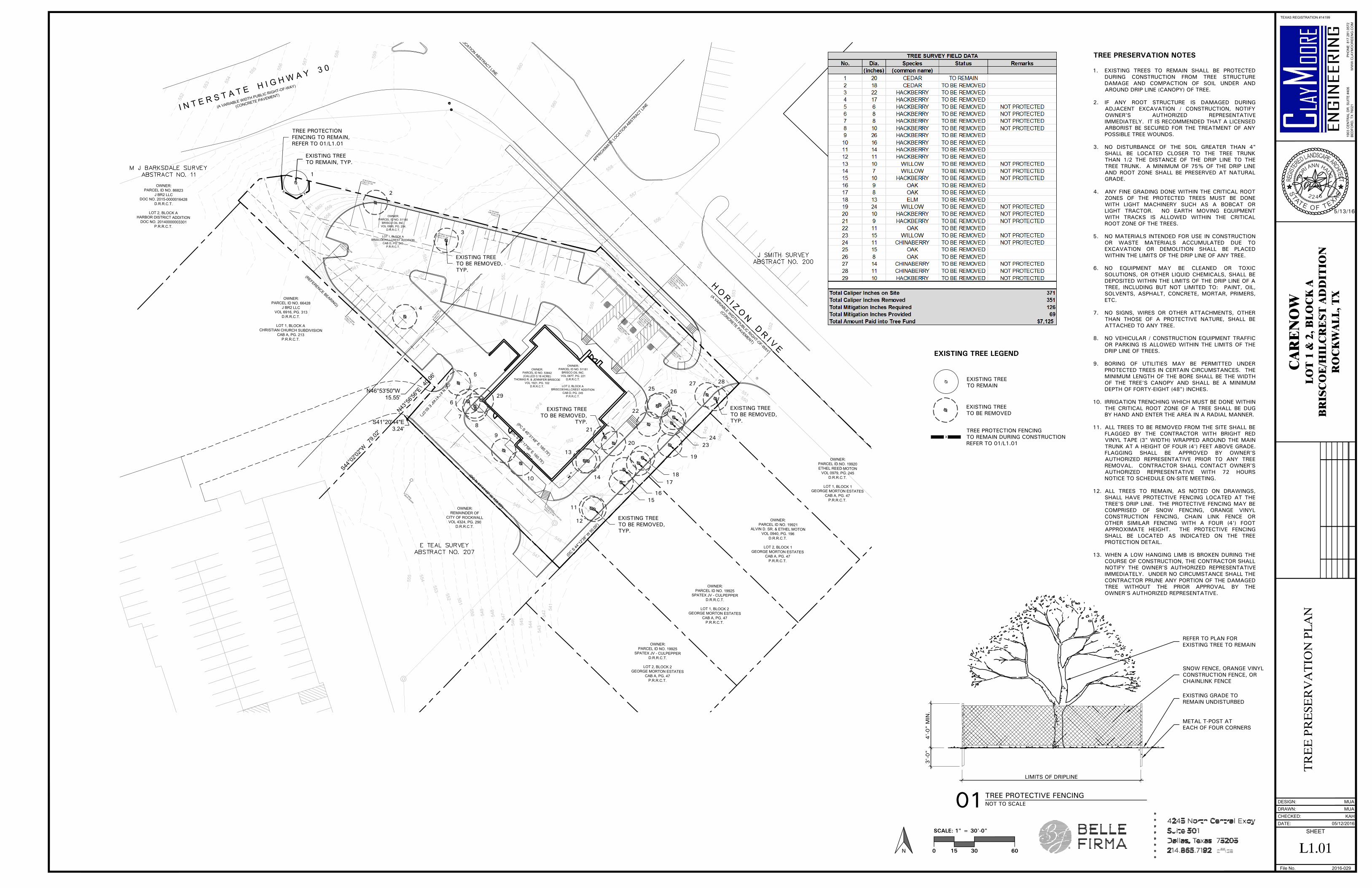
TREE PRESERVATION NOTES
1. EXISTING TREES TO REMAIN SHALL BE PROTECTED
DURING CONSTRUCTION FROM TREE STRUCTURE
DAMAGE AND COMPACTION OF SOIL UNDER AND
AROUND DRIP LINE (CANOPY) OF TREE.
2. IF ANY ROOT STRUCTURE IS DAMAGED DURING
ADJACENT EXCAVATION / CONSTRUCTION, NOTIFY
OWNER'S AUTHORIZED REPRESENTATIVE
IMMEDIATELY. IT IS RECOMMENDED THAT A LICENSED
ARBORIST BE SECURED FOR THE TREATMENT OF ANY
POSSIBLE TREE WOUNDS.
3. NO DISTURBANCE OF THE SOIL GREATER THAN 4"
SHALL BE LOCATED CLOSER TO THE TREE TRUNK
THAN 1/2 THE DISTANCE OF THE DRIP LINE TO THE
TREE TRUNK. A MINIMUM OF 75% OF THE DRIP LINE
AND ROOT ZONE SHALL BE PRESERVED AT NATURAL
GRADE.
4. ANY FINE GRADING DONE WITHIN THE CRITICAL ROOT
ZONES OF THE PROTECTED TREES MUST BE DONE
WITH LIGHT MACHINERY SUCH AS A BOBCAT OR
LIGHT TRACTOR. NO EARTH MOVING EQUIPMENT
WITH TRACKS IS ALLOWED WITHIN THE CRITICAL
ROOT ZONE OF THE TREES.
5. NO MATERIALS INTENDED FOR USE IN CONSTRUCTION
OR WASTE MATERIALS ACCUMULATED DUE TO
EXCAVATION OR DEMOLITION SHALL BE PLACED
WITHIN THE LIMITS OF THE DRIP LINE OF ANY TREE.
6. NO EQUIPMENT MAY BE CLEANED OR TOXIC
SOLUTIONS, OR OTHER LIQUID CHEMICALS, SHALL BE
DEPOSITED WITHIN THE LIMITS OF THE DRIP LINE OF A
TREE, INCLUDING BUT NOT LIMITED TO: PAINT, OIL,
SOLVENTS, ASPHALT, CONCRETE, MORTAR, PRIMERS,
ETC.
7. NO SIGNS, WIRES OR OTHER ATTACHMENTS, OTHER
THAN THOSE OF A PROTECTIVE NATURE, SHALL BE
ATTACHED TO ANY TREE.
8. NO VEHICULAR / CONSTRUCTION EQUIPMENT TRAFFIC
OR PARKING IS ALLOWED WITHIN THE LIMITS OF THE
DRIP LINE OF TREES.
9. BORING OF UTILITIES MAY BE PERMITTED UNDER
PROTECTED TREES IN CERTAIN CIRCUMSTANCES. THE
MINIMUM LENGTH OF THE BORE SHALL BE THE WIDTH
OF THE TREE'S CANOPY AND SHALL BE A MINIMUM
DEPTH OF FORTY-EIGHT (48") INCHES.
10. IRRIGATION TRENCHING WHICH MUST BE DONE WITHIN
THE CRITICAL ROOT ZONE OF A TREE SHALL BE DUG
BY HAND AND ENTER THE AREA IN A RADIAL MANNER.
11. ALL TREES TO BE REMOVED FROM THE SITE SHALL BE
FLAGGED BY THE CONTRACTOR WITH BRIGHT RED
VINYL TAPE (3" WIDTH) WRAPPED AROUND THE MAIN
TRUNK AT A HEIGHT OF FOUR (4') FEET ABOVE GRADE.
FLAGGING SHALL BE APPROVED BY OWNER'S
AUTHORIZED REPRESENTATIVE PRIOR TO ANY TREE
REMOVAL. CONTRACTOR SHALL CONTACT OWNER'S
AUTHORIZED REPRESENTATIVE WITH 72 HOURS
NOTICE TO SCHEDULE ON-SITE MEETING.
12. ALL TREES TO REMAIN, AS NOTED ON DRAWINGS,
SHALL HAVE PROTECTIVE FENCING LOCATED AT THE
TREE'S DRIP LINE. THE PROTECTIVE FENCING MAY BE
COMPRISED OF SNOW FENCING, ORANGE VINYL
CONSTRUCTION FENCING, CHAIN LINK FENCE OR
OTHER SIMILAR FENCING WITH A FOUR (4') FOOT
APPROXIMATE HEIGHT. THE PROTECTIVE FENCING
SHALL BE LOCATED AS INDICATED ON THE TREE
PROTECTION DETAIL.
13. WHEN A LOW HANGING LIMB IS BROKEN DURING THE
COURSE OF CONSTRUCTION, THE CONTRACTOR SHALL
NOTIFY THE OWNER'S AUTHORIZED REPRESENTATIVE
IMMEDIATELY. UNDER NO CIRCUMSTANCE SHALL THE
CONTRACTOR PRUNE ANY PORTION OF THE DAMAGED
TREE WITHOUT THE PRIOR APPROVAL BY THE
OWNER'S AUTHORIZED REPRESENTATIVE.
4'-
0" M
IN.
3'-
0"
LIMITS OF DRIPLINE
01TREE PROTECTIVE FENCINGNOT TO SCALE
REFER TO PLAN FOR
EXISTING TREE TO REMAIN
EXISTING GRADE TO
REMAIN UNDISTURBED
METAL T-POST AT
EACH OF FOUR CORNERS
SNOW FENCE, ORANGE VINYL
CONSTRUCTION FENCE, OR
CHAINLINK FENCE
X
EXISTING TREE
TO BE REMOVED
TREE PROTECTION FENCING
TO REMAIN DURING CONSTRUCTION
REFER TO 01/L1.01
EXISTING TREE
TO REMAIN
EXISTING TREE LEGEND

0.0 0.0 0.0 0.0 0.0 0.0 0.0 0.0
0.0 0.0 0.0 0.1 0.1 0.1 0.1 0.0 0.0 0.0
0.0 0.0 0.1 0.1 0.2 0.2 0.2 0.1 0.0 0.0 0.0 0.0
0.0 0.0 0.0 0.1 0.2 0.5 0.7 0.4 0.2 0.1 0.0 0.0 0.0 0.0
0.0 0.0 0.0 0.1 0.2 0.5 1.2 1.3 1.0 0.5 0.2 0.0 0.0 0.0 0.0 0.0
0.0 0.0 0.0 0.1 0.1 0.6 1.2 1.5 2.3 2.3 1.4 0.2 0.1 0.0 0.0 0.0 0.0 0.0
0.0 0.0 0.0 0.1 0.2 0.5 1.8 2.9 1.6 1.8 2.4 1.7 0.7 0.4 0.1 0.0 0.0 0.0 0.0 0.0
0.0 0.0 0.0 0.1 0.1 0.5 1.4 2.6 3.1 3.1 2.3 2.5 1.1 0.5 0.1 0.0 0.0 0.0 0.0 0.0
0.0 0.0 0.0 0.1 0.1 0.4 1.3 2.5 3.1 2.2 2.6 2.6 0.9 0.3 0.1 0.1 0.1 0.0 0.0 0.0
0.0 0.0 0.0 0.1 0.1 0.3 0.9 2.4 2.7 3.1 2.4 2.0 0.9 0.3 0.1 0.1 0.1 0.1 0.0 0.0
0.0 0.0 0.0 0.1 0.1 0.2 0.7 1.3 2.6 3.0 2.2 4.0 1.9 0.7 0.3 0.2 0.1 0.1 0.1 0.0 0.0
0.0 0.0 0.0 0.1 0.2 0.6 1.4 1.9 1.7 3.1 1.9 2.6 1.1 0.6 0.3 0.2 0.1 0.1 0.0 0.0 0.0
0.0 0.0 0.0 0.0 0.1 0.3 0.7 1.3 2.4 3.0 2.5 2.0 0.9 0.6 0.3 0.2 0.1 0.1 0.0 0.0 0.0
0.0 0.0 0.0 0.1 0.1 0.2 0.7 1.3 2.1 3.2 1.5 1.2 1.0 0.5 0.3 0.1 0.1 0.0 0.0 0.0 0.0
0.0 0.0 0.0 0.1 0.1 0.5 1.2 1.5 1.8 1.7 3.1 0.6 0.6 1.1 1.1 0.7 0.4 0.2 0.1 0.0 0.0 0.0 0.0
0.0 0.0 0.0 0.1 0.8 1.2 2.0 2.5 1.9 2.0 2.5 3.3 0.6 0.8 1.2 1.6 1.7 1.0 0.5 0.1 0.0 0.0 0.0 0.0
0.0 0.0 0.0 0.1 0.3 1.1 1.2 1.6 2.5 2.1 2.1 2.0 2.2 1.9 0.4 0.6 0.8 1.3 1.3 1.1 1.5 1.0 0.3 0.0 0.0 0.0 0.0
0.0 0.0 0.0 0.1 0.3 1.1 1.5 1.4 1.8 2.1 2.0 1.7 1.5 1.4 1.6 0.4 0.7 1.1 1.2 1.8 1.3 1.1 1.1 0.3 0.0 0.0 0.0 0.0
0.0 0.0 0.0 0.1 0.3 0.9 1.2 1.7 1.8 1.5 1.6 1.9 1.7 1.4 1.3 1.6 1.7 0.9 0.7 1.0 1.5 1.4 1.7 1.4 1.1 0.5 0.0 0.0 0.0 0.0
0.0 0.0 0.1 0.1 0.4 1.2 1.3 1.2 1.4 1.3 1.0 1.3 1.7 1.8 1.6 1.7 1.7 1.9 1.7 1.2 1.0 1.2 1.5 1.2 1.3 1.1 0.2 0.1 0.0 0.0 0.0
0.0 0.0 0.1 0.1 0.9 1.1 1.6 1.8 1.4 1.4 1.2 0.9 1.2 1.7 2.0 2.0 1.8 1.9 1.9 1.9 1.7 1.6 1.7 1.8 1.2 0.8 0.4 0.0 0.0 0.0 0.0
0.0 0.0 0.0 0.1 0.1 0.6 1.2 1.2 1.5 1.9 1.5 1.4 1.2 1.1 1.2 1.8 2.1 2.0 1.8 2.0 1.9 1.6 1.8 1.2 1.2 1.4 1.0 0.3 0.1 0.0 0.0 0.0
0.0 0.0 0.0 0.0 0.1 0.7 1.2 1.9 1.3 1.8 1.6 1.4 1.2 1.4 1.6 1.5 1.8 2.2 2.0 2.0 1.8 1.6 1.7 1.9 1.2 1.2 0.8 0.2 0.0 0.0 0.0 0.0
0.0 0.0 0.0 0.0 0.1 0.3 0.6 1.3 2.0 1.8 1.7 1.6 1.6 1.5 1.6 1.8 1.8 2.1 1.4 1.3 2.0 1.7 1.2 1.2 1.2 1.0 0.6 0.1 0.0 0.0 0.0 0.0
0.0 0.0 0.0 0.0 0.0 0.1 0.3 0.5 0.9 1.5 1.6 1.5 1.8 1.8 1.6 2.2 1.8 1.8 1.8 1.3 1.3 1.2 1.2 0.9 0.7 0.7 0.2 0.0 0.0 0.0 0.0 0.0
0.0 0.0 0.0 0.0 0.1 0.1 0.2 0.4 0.7 1.1 1.3 1.7 2.0 1.3 1.3 1.6 1.5 1.3 1.3 0.9 1.0 0.4 0.3 0.3 0.2 0.1 0.0 0.0 0.0 0.0 0.0
0.0 0.0 0.0 0.0 0.1 0.1 0.2 0.3 0.4 0.7 0.8 1.3 1.4 1.2 1.4 0.9 0.7 0.4 0.2 0.1 0.1 0.1 0.1 0.0 0.0 0.0 0.0 0.0 0.0 0.0
0.0 0.0 0.0 0.0 0.0 0.1 0.1 0.2 0.3 0.4 0.5 0.7 0.7 0.3 0.2 0.1 0.1 0.1 0.0 0.0 0.0 0.0 0.0 0.0 0.0 0.0 0.0 0.0 0.0
0.0 0.0 0.0 0.0 0.0 0.1 0.1 0.1 0.2 0.2 0.1 0.1 0.1 0.1 0.1 0.1 0.0 0.0 0.0 0.0 0.0 0.0 0.0 0.0 0.0 0.0 0.0 0.0
0.0 0.0 0.0 0.0 0.0 0.0 0.0 0.0 0.1 0.1 0.1 0.0 0.0 0.0 0.0 0.0 0.0 0.0 0.0 0.0 0.0 0.0 0.0 0.0 0.0 0.0 0.0
fh
555.428
36
wv
555.547
37
wv
555.428
39
wv
556.173
55
gasplm
562.346
119
gasplm
561.488
124
fh
559.630
137
wv
560.320
138
pp
542.807
232
pp
556.597
233
stmh
551.373
329
W
Calculation Summary
Label UnitsAvg Max
Min Avg/Min Max/MinPtSpcLr PtSpcTb
10 10MAIN PARKING SUMMARY Fc1.49 2.5 0.6 2.48 4.17
REAR AND DRIVE Fc1.04 3.2 0.1 10.40 32.00
WLS11149 CARE NOW ROCKWALL, TX PM: DAVID PLEASE EMAIL FOR PRICING AT [email protected]
Symbol Qty Label Total Lamp Lumens LLFDescription
Lum. Watts
6A N.A.
0.950 WLS-CLS-30L-1-5K-4-BC 20' MOUNTING HEIGHT 70.4
1 B N.A.0.950 WLS-CLS-30L-1-5K-5M 20' MOUNTING HEIGHT 73.3
4 C N.A.0.950 WLS-WMKL-WT-LED-28-350-CW-UE 16' MOUNTING HEIGHT 34
4 D N.A.0.950 WLS-WMKL-FP-LED-28-350-CW-UE 16' MOUNTING HEIGHT 34
Luminaire Schedule
Based on the information provided, all dimensions and luminaire locationsshown represent recommended positions. The engineer and/or architectmust determine applicability of the layout to existing or future fieldconditions.This lighting pattern represents illumination levels calculated fromlaboratory data taken under controlled conditions utilizing currentindustry standard lamp ratings in accordance with IlluminatingEngineering Society approved methods. Actual performance of anymanufacturer's luminaire may vary due to variation in electrical voltage,tolerance in lamps and other variable field conditions.
REVISIONSRev # Date BY:
80
0-6
33
-87
11
DATE - 5
/12/1
6
CAR
E N
OW
RO
CKW
ALL,
TX
WLS
- 11149
scale: 1"=
20'
19
19
WIN
DS
OR
PLAC
EFO
RT W
OR
TH
, TX 7
61
10
www.w
lslig
htin
g.c
om
PM
:DAVID
BY: D
.T.
SH
EET 1
OF 1
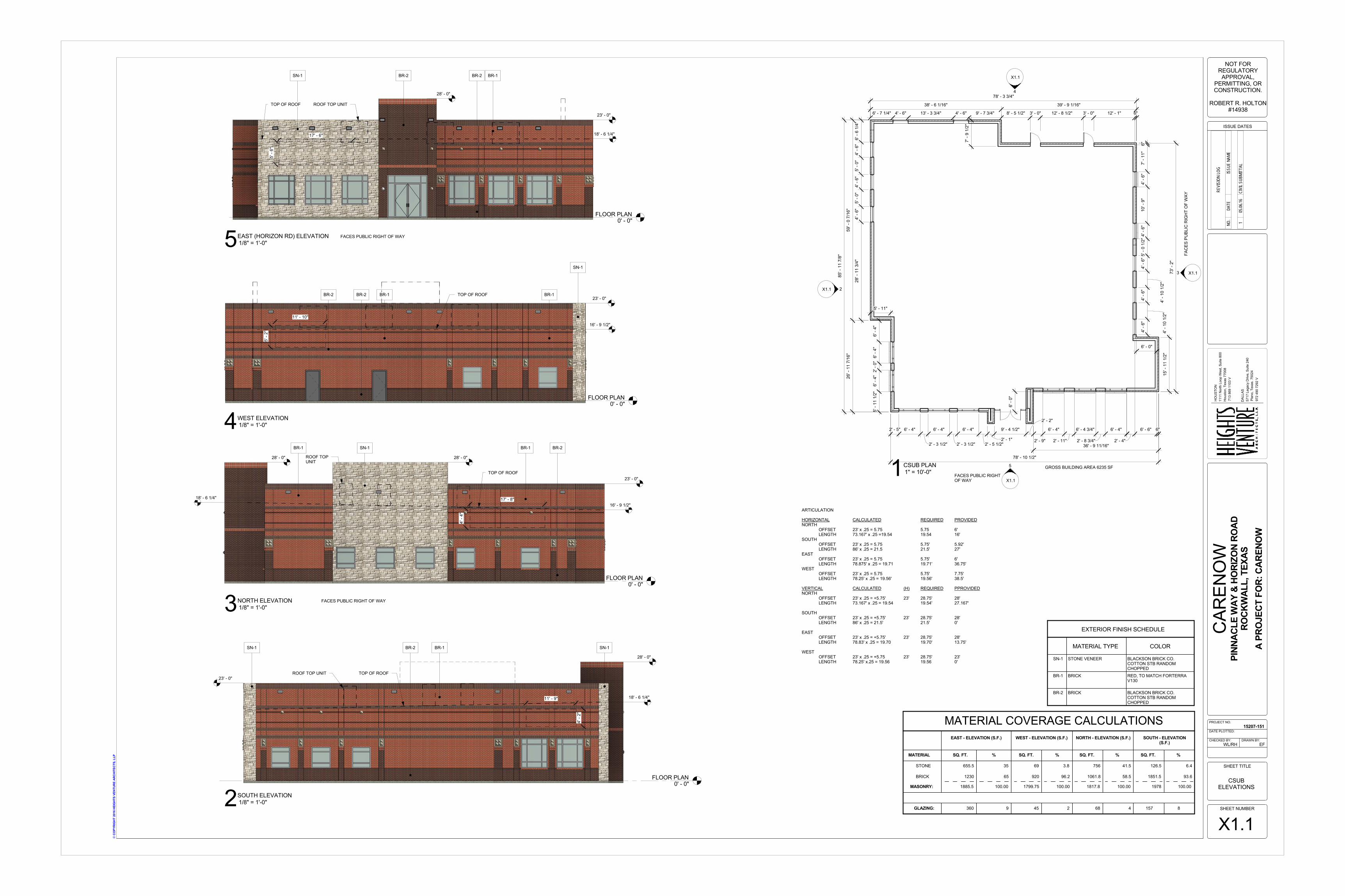
2' - 5" 6' - 4"
2' - 3 1/2"
6' - 4"
2' - 3 1/2"
6' - 4"
2' - 5 1/2"2' - 1"
9' - 4 1/2"
2' - 2"
2' - 9"
6' - 4"
2' - 11"
6' - 4 3/4"
2' - 8 3/4"
6' - 4"
6' -
6 1/
4"4'
- 6"
5' -
0"4'
- 6"
5' -
0"4'
- 6"
28' -
11
3/4"
X1.1
4
X1.13
X1.1
5
X1.1 2
6' -
4"6'
- 4"
2' -
0"6'
- 4"
5' -
11 1
/2"
4' -
6"
4' -
10 1
/2"
4' -
6"
4' -
10 1
/2"
4' -
6"5'
- 0
1/2"
4' -
6"10
' - 9
"4'
- 6"
7' -
11"
6"
6' - 0"
78' - 3 3/4"
6' - 7 1/4" 4' - 6" 13' - 3 3/4" 4' - 6" 9' - 7 3/4" 8' - 5 1/2" 3' - 0" 12' - 8 1/2" 3' - 0" 12' - 1" 6"
5' - 11"
6' -
0"
78' - 10 1/2"
2' - 4"
6' - 6" 6"
7' -
9 1/
2"
85' -
11
7/8"
59' -
0 7
/16"
26' -
11
7/16
"
GROSS BUILDING AREA 6235 SF
15' -
11
1/2"
73' -
2"
38' - 6 1/16" 39' - 9 1/16"
36' - 9 11/16"
FACES PUBLIC RIGHTOF WAY
FAC
ES P
UBL
IC R
IGH
T O
F W
AY
FLOOR PLAN0' - 0"
BR-2
SN-1
BR-2
16' - 9 1/2"
5' -
2"
11' - 10"
23' - 0"BR-1 TOP OF ROOF BR-1
FLOOR PLAN0' - 0"
SN-1 BR-1
17' - 8"
4' -
4"
23' - 0"
28' - 0"
BR-1
TOP OF ROOF
28' - 0"
BR-2
18' - 6 1/4"
ROOF TOPUNIT
16' - 9 1/2"
FLOOR PLAN0' - 0"
SN-1 BR-2 BR-1
5' -
6"
17' - 6"
28' - 0"
TOP OF ROOF
BR-2
23' - 0"
18' - 6 1/4"
ROOF TOP UNIT
FLOOR PLAN0' - 0"
SN-1 BR-1
11' - 9"
4' -
2"
28' - 0"
23' - 0"TOP OF ROOF
SN-1BR-2
18' - 6 1/4"
ROOF TOP UNIT
MATERIAL COVERAGE CALCULATIONSEAST - ELEVATION (S.F.) WEST - ELEVATION (S.F.) NORTH - ELEVATION (S.F.) SOUTH - ELEVATION
(S.F.)
MATERIAL
MASONRY:
GLAZING:
STONE
SQ. FT. % SQ. FT. % SQ. FT. % SQ. FT. %
1817.8
756
1978
126.5
1799.75
69
45
1885.5
655.5
360
100.00
35
9
100.00
3.8
2
100.00
41.5
100.00
6.4
68 4
BRICK 1061.8 1851.59201230 65 96.2 58.5 93.6
157 8
SN-1 STONE VENEER
BRICK
BRICK
BLACKSON BRICK CO.COTTON STB RANDOMCHOPPEDRED, TO MATCH FORTERRAV130
BLACKSON BRICK CO.COTTON STB RANDOMCHOPPED
MATERIAL TYPE COLOR
EXTERIOR FINISH SCHEDULE
BR-1
BR-2
DAL
LAS
5717
Leg
acy
Driv
e, S
uite
240
Plan
o, T
exas
. 750
2497
2 49
0 72
92 V
HO
UST
ON
1111
Nor
th L
oop
Wes
t, Su
ite 8
00H
oust
on, T
exas
770
0871
3 86
9 11
03 V
©CO
PYRI
GHT
201
6 HE
IGHT
S VE
NTUR
E AR
CHIT
ECTS
, LLP
DRAWN BY:CHECKED BY:
DATE PLOTTED:
PROJECT NO.
SHEET NUMBER
SHEET TITLE
ISSUE DATES
NOT FORREGULATORY
APPROVAL,PERMITTING, ORCONSTRUCTION.
ROBERT R. HOLTON#14938
WL/RH EF
15207-151
CSUBELEVATIONS
X1.1
CAR
ENO
WPI
NNAC
LE W
AY &
HO
RIZO
N RO
ADRO
CKW
ALL,
TEX
ASA
PRO
JECT
FO
R: C
AREN
OW
1" = 10'-0"1CSUB PLAN
1/8" = 1'-0"4WEST ELEVATION
1/8" = 1'-0"3NORTH ELEVATION
1/8" = 1'-0"5EAST (HORIZON RD) ELEVATION
1/8" = 1'-0"2SOUTH ELEVATION
REVI
SION
LOG
NO.
DATE
ISSU
E NA
ME
105
.06.16
CIVI
L SUB
MITT
AL
ARTICULATION
HORIZONTAL CALCULATED REQUIRED PROVIDEDNORTH
OFFSET 23' x .25 = 5.75 5.75 6'LENGTH 73.167' x .25 =19.54 19.54 16'
SOUTHOFFSET 23' x .25 = 5.75 5.75' 5.92'LENGTH 86' x .25 = 21.5 21.5' 27'
EASTOFFSET 23' x .25 = 5.75 5.75' 6'LENGTH 78.875' x .25 = 19.71 19.71' 36.75'
WESTOFFSET 23' x .25 = 5.75 5.75' 7.75'LENGTH 78.25' x .25 = 19.56' 19.56' 38.5'
VERTICAL CALCULATED (H) REQUIRED PPROVIDEDNORTH
OFFSET 23' x .25 = +5.75' 23' 28.75' 28'LENGTH 73.167' x .25 = 19.54 19.54' 27.167'
SOUTHOFFSET 23' x .25 = +5.75' 23' 28.75' 28'LENGTH 86' x .25 = 21.5' 21.5' 0'
EASTOFFSET 23' x .25 = +5.75' 23' 28.75' 28'LENGTH 78.83' x .25 = 19.70 19.70' 13.75'
WESTOFFSET 23' x .25 = +5.75 23' 28.75' 23'LENGTH 78.25' x.25 = 19.56 19.56 0'
FACES PUBLIC RIGHT OF WAY
FACES PUBLIC RIGHT OF WAY

CARENOWNEW MEDICAL CARE ROCKWALL, TX
NOT FOR REGULATORY APPROVAL, PERMITTING, OR CONSTRUCTION. ROBERT R. HOLTON #14938
SN-1 BR-2 BR-1
SN-1 STONE-BLACKSON BRICK- COTTON STB RANDOM CHOPPED
BR-2 BRICK-BURGANDY, TO MATCH FORTERRA V180
BR-1 BRICK-RED, TO MATCH FORTERRA V130