feko release notes - alloptic designs
TRANSCRIPT
Release Notes for FEKO Suite 6.3October 2013
(Changes since FEKO Suite 6.2)FEKO Suite 6.3 boasts many extensions to both the user interface and the electromagnetic solver.Highlights of the Suite 6.3 release include support for higher order basis functions (HOBF) oncurvilinear surface elements for both the method of moments (MoM) and multilevel fast multipolemethod (MLFMM). CAD import and export filters are now part of the default FEKO installation forall licenced FEKO users. CADFEKO also includes advanced CAD healing and reconstruction tools.Significant extensions were also implemented for cable and windscreen modelling that simplifymodel construction and configuration. Application automation has been extended to CADFEKOand application macros have been introduced to CADFEKO and POSTFEKO allowing users to ex-tend the applications by means of macro scripts. Characteristic modes have been extended tocalculate the modal excitation coefficients as well as to perform mode tracking by correlatingmodes calculated at different frequencies. Speed improvements have been made to the calcula-tion of far fields and the option to compute continuous far fields versus angle is now supported.These are just a few of the features available in the Suite 6.3 release. The sections that follow willelaborate on these and other improvements.
Note that you will require a new licence file that supports FEKO Suite 6.3. This licence file is alsovalid for older FEKO releases, thus conveniently allowing the usage of multiple FEKO versions ifrequired.
The more prominent new features are listed below. Many smaller bug fixes and extensions havebeen included in addition to the listed items.
Prominent features in FEKO Suite 6.3
1. Higher order basis functions (HOBF) for the method of moments (MoM) were included inthe previous release. The support for HOBF has been extended to curvilinear surface meshes(second order curvilinear triangles with 6 vertex points). Curvilinear surface meshes allowusers to utilise large HOBF elements on models that previously had to use lower order ortraditional basis functions to accurately represent the model curvature. Higher order basisfunctions are now supported for the multilevel fast multipole method (MLFMM) furtherreducing the memory requirement for large models. Significant speed improvements for theHOBF matrix fill phase have been achieved which reduces the required solution time.
2. The CAD import and export filters are now available to all licensed users without any addi-tional costs. The CAD and mesh import tools have been improved by automatically selectingthe appropriate file type and import settings. The import tools provide easy access to theimport log and import settings. All import settings have been revised and optimised for thevarious import formats.
3. CAD healing tools have been developed that allow the most common CAD errors to becorrected swiftly. The tools include the following:

• Repair part: Heals a body by removing and repairing common geometry faults in anattempt to create a valid solid.
• Simplify part representation: Simplifies a curve or a surface by using analytical andmore robust representations of the entities.
• Repair edges: Repairs inaccuracies in the edges of a sheet or a solid body by recalculat-ing edge and vertex geometry to a specified precision wherever possible.
• Repair and sew faces: Repairs problems in the faces of the selected part then tries tosew them into a solid or sheet part.
• Remove small features: Removes small features such as edges, faces, spikes and gashesfrom the input parts.
A hole-filling tool has been included that allows a face to be reconstructed from its boundingedges. This tool is often useful in cases where the face cannot be healed or is missing. Anew selection tool has been developed for selecting the smallest loop of laminar edges thatinclude the currently selected edges.
The CAD healing tools, including the hole-filling tool, only work on primitive parts and don’tsupport parametric re-evaluation.
4. The application automation framework that was already powerful has been extended fur-ther. Application automation has been included in CADFEKO allowing users to create geom-etry using scripts. Only a subset of CADFEKO is accessible through the Lua scripting interfaceand the rest will be made available in future releases.
Application macros are available in CADFEKO and POSTFEKO allowing users to create theirown tools or download scripts from the FEKO website and then have them readily availablein the GUI interface. Forms or dialogs can be used to obtain user input during the executionof the script. This allows users to expand the capabilities of POSTFEKO without having toopen the scripting editor each time a custom script is executed.
5. A new set of windscreen construction tools have been developed. The main new feature isa constrained surface tool that creates a windscreen work surface analogous to a CADFEKOwork plane. This surface is easily specified and conforms to the shape of the windscreen.Antennas in the windscreen can then be defined in this work surface, using a regular 2Dwork plane which is then automatically mapped to the shape of the windscreen in 3D space.Antennas in this work surface can be specified using wires, Bézier curves and regularlyspaced wires.
6. EDITFEKO has been completely rewritten and now boasts a number of new features. Theseinclude:
• A new ribbon interface similar to the other GUI components.
• A search bar allows users to quickly find the correct card.
• Window tabs (multiple files) can be re-ordered.
• Support for drag and drop of files.
• Syntax highlighting that makes editing files easier.
• Request, source and load names are included on the card panels (not just a commentat the end of the first line of the card).
7. The calculation of far fields has been accelerated by implementing a new method based ona spherical wave expansion. This allows in particular the plotting of continuous far fielddata that can be sampled to any resolution in POSTFEKO. The feature is attractive for thesimulation of large gain antennas or RCS of large objects, where normally the far field/RCSversus angle would show a ripple requiring a fine angular resolution.

User interface
The GUI components have been extended to support new features and solution techniques in theFEKO kernel. In addition to supporting new kernel features, other new features have also beenimplemented. These features are listed in the sections that follow.
3D CAD modeller - CADFEKO
The prominent new features that have been implemented in CADFEKO, in addition to the featureslisted earlier, are highlighted in the following list.
1. More than 450 smaller extensions and bug fixes.
2. Geometry and mesh parts can be excluded from the model. An excluded part can remainpart of the model, but will not be meshed, taken into account during CEM validation or beincluded as part of the simulation.
3. Configurations can be excluded from a model. Excluded configurations will remain part ofthe model, but will not be solved.
4. Support for curvilinear surface mesh elements has been added to all components:
• Curvilinear surface meshes can be generated when the solution method supports curvi-linear elements.
• Both geometry and mesh parts of surfaces can be used to generate curvilinear meshes.
• Visualisation support was implemented for curvilinear surface meshes.
5. Numerous extensions and improvements were made to the cable modelling interface. Someof these are listed below:
• Cables and cable components can be selected in the 3D view.
• The snapping tool allows a snap offset to be set allowing users to quickly add cablepaths at a constant distance from the model faces. It is also possible to snap to cablepaths.
• Searching for cables by specifying a subset of the names of the relevant cable harness,connector, path and cable instance is possible with the “Find cable” tool.
• Cable conductors can be combined into more complex cable bundles.
• Rectangle selection has been implemented for the schematic view allowing multipleitems to be selected at the same time.
• The projection of the cable network in 3D view to cable schematic view has been ex-tended by allowing the user to select the most appropriate projection.
• The distance between connectors displayed on the schematic view can be varied toprevent connectors from overlapping.
6. All dialogs that create entities allow the user to create a single entity or multiple entities.These dialogs now have “Create”, “Add” and “Close” buttons.
7. The ribbon in CADFEKO has a new “Home” tab, similar to POSTFEKO and EDITFEKO.
8. The performance of rendering table contents in the dialogs has been improved.
9. The command line option in CADFEKO_BATCH to change the cable seed value has changedfrom -cable_seed=SEEDVALUE to --cable-seed SEEDVALUE.

Post-processor - POSTFEKO
The major new features that have been implemented in POSTFEKO, in addition to the featureslisted earlier, are highlighted in the following list.
1. More than 300 smaller extensions and bug fixes.
2. Curvilinear and HOBF mesh support have been added to POSTFEKO.
• Curvilinear surface meshes are visualised in the 3D view.
• Currents and charges can be displayed on flat or curvilinear meshes when using higherorder basis functions.
3. The application automation and Lua scripting interface in POSTFEKO has been extended. Inaddition to the items listed under the prominent features, the following improvements arealso available.
• Dataset improvements: The structure used for containing math results has been im-proved for performance and memory overhead. Datasets are now also accessible fromthe application automation framework. This change could cause scripts to stop workingdue to changes in the the syntax, but they can be corrected with minor changes.
• POSTFEKO can be launched in a non-interactive mode to execute an application au-tomation script using --non-interactive as a command line argument. In thismode no dialogs are displayed and default options are selected for any dialogs thatwould have required a user to select an option. If the script execution fails, the appli-cation exits with an error code.
• Two new matrix manipulation objects have been developed that allow complex anddouble (real) matrix operations from the scripting environment.
• Extended automation API for the renaming of window tabs.
• Parameters can be sent to scripts when launching POSTFEKO from a command line.
• A batch modify function for Lua objects has been implemented.
• A number of commonly used Lua scripting modules have been included by default withthe FEKO installation. These include LuaFileSystem, LuaXml, winapi and the toolsprovided by PenLight. This is in addition to the luacom module that was also shippedwith earlier version for COM manipulation of application on Windows.
• Further improvements and extensions have been made to the documentation examplesmaking it easier to develop scripts.
4. When displaying port impedances in Smith charts or when calculating insertion losses, thereference impedance specified for the port will be used instead of defaulting to 50 Ω. It isstill possible to use an alternative reference impedance.
5. Standing wave ratio and mismatch loss quantities are now available for waveguide andmodal excitations.

Importing and exporting
1. External mesh import using the ABAQUS file format has been improved (by adding supportfor additional keywords and updating to the latest ABAQUS specification).
2. The support of both KEYOPT and KEYOP for the external ANSYS CDB mesh file formatimport has been extended. Numerous other improvements such as non-continuous nodenumbering and splitting of quadrangles into triangles have also been included.
3. The CONCEPT file import has been updated to support their latest file format (includingwire radius and number of segments)
4. Exported NASTRAN mesh files support curvilinear triangles (CTRIA6 element type).
Electromagnetic solution kernel
In addition to the prominent features mentioned above, the following new features have beenimplemented.
General kernel improvements and extensions
1. More than 400 smaller extensions and bug fixes.
2. Performance has been improved by updating to the latest math libraries and compilers. (ForAMD platforms it was confirmed that ACML is superior in performance to Intel MKL, keepingdifferent binaries for each platform).
3. A check has been included to prevent optimisation runs when adaptive frequency interpola-tion is used.
4. Continuous frequency interpolation settings (which blocks to include etc.) in connectionwith characteristic mode analysis have been adjusted.
5. The treatment of cases with singular fields (e.g. near field calculation when observationpoints intersect with mesh surfaces) has been improved.
6. Series and parallel RLC circuits are now also supported for edge ports.
7. Closed FEM problems, i.e. completely confined by PEC and/or modal port boundaries, arenow detected and the MoM solver is deactivated automatically resulting in faster solutions.
8. Large parallel MLFMM and FEM/MLFMM iterative solutions suffered from problems duringthe distributed, sparse LU preconditioner calculation (crashes, memory spikes, 4-Byte integerlimitation, etc.). Changes to improve robustness and stability include:
• An alternate parallel, distributed sparse library, the MUltifrontal Massively ParallelSolver (MUMPS), as default for the calculation of the sparse LU preconditioners ofthe MLFMM and FEM has been introduced.
• Out-of-core sparse LU factorisation is employed when the memory requirement for anin-core factorisation is too high.
• Sparse LU preconditioner out-of-core capability is supported for sequential runs on IntelMKL platforms (PARDISO) and for parallel, distributed runs (MUMPS).
9. A number of cable modelling extensions have been included:

• The concept of a cable harness has been introduced.
– Grouping of cable paths that are connected via circuit elements and not necessarilyconnected.
– A cable harness affects coupling calculations since LC coupling only between con-ductors/signals that are grouped in a bundle cross section.
– Field coupling only between different harnesses, i.e. not between cables in a singleharness.
• Multiple signals may be connected to a single connector and pin.
• Reading of previous solution results is supported (*.str file), i.e. cable radiation/irradiationresults can be re-used.
• SPICE circuit files including the equivalent model for MTL harnesses can be exported,allowing post-processing in an external circuit simulator.
10. Parallel performance and scaling of MPI-based FEKO MoM solutions have been improvedfor large problems and/or a large number of parallel processes by changing the process gridlayout from 1D block cyclic row distribution to a 2D block cyclic distribution scheme.
11. Calculation time for extracting spherical mode coefficients has been reduced significantly.
12. The number of spherical modes required to capture the full radiated power can automaticallybe determined.
13. The internal formulations for spherical modes have been changed to avoid numerical stabil-ity problems for higher mode indices.
14. The ideal receiving antenna now also supports definitions using spherical modes or nearfield apertures in addition to the far field pattern that has been available.
15. Domain decomposition techniques such as the numerical Green’s function and the fast arraysolver support higher order basis functions and curvilinear triangle elements.
16. The finite antenna array solver has been extended to support discrete loads on wires, coat-ings and lossy metals.
17. The finite antenna array solver also now supports rotated elements in the array.
18. Characteristic mode calculations have been extended to support calculating modal excitationcoefficients.
19. Characteristic modes are now tracked by correlating modes between frequency runs.
20. Characteristic mode calculations are available for dielectric and magnetic materials and alsofor Green’s function aperture elements.
21. The performance of the periodic boundary condition calculation has been improved greatly.
22. Finite conductivity of metallic faces, thin dielectric sheets, and coated PEC surfaces are nowsupported for UTD (reflection only, no transmission is taken into account).
23. Coatings on the surface of dielectric bodies supported with MoM. This is not supported forMLFMM.
Support components, installation, and licensing
1. The date and time when the “secfeko.dat” licence file was created is now available for sup-port purposes in the secfeko -p output and also in SECFEKO_GUI.
2. Updated the Sentinel dongle handling by disabling the check for terminal services (avoidsdelays at startup and works with remote desktops automatically, no longer need to set aspecial environment variable in this case).
3. A new setting -1 is available for the environment variable FEKO_SECFEKO_USE_DONGLEto disable the usage of the dongle (i.e. functions will not be called). 0 is default and 1 wasalready there to force using a dongle (and then trigger fatal errors).
4. A check for synchronous times has been included when using multiple floating licenceservers.
5. Similar to 32-bit, for 64-bit the Intel and AMD versions are now integrated into one singleinstallation archive (applies to both Windows and Linux). The detection of which FEKOkernel to launch on which platform is done at run-time.
6. The Catia V5 import/export filter (only available for Windows) used to be a separate instal-lation (a separate download). It is now integrated into the main FEKO installation.
7. A unified versioning scheme 6.3-xxx is used across all the FEKO components where 6.3indicates the FEKO Suite and xxx is a build number of each individual component.
8. Please note that the FEKO installer now requires Windows Installer version 4.5 or newer,which is available on Windows Vista SP2 and later systems. Where required it is automati-cally installed by the setup executable. However when using the MSI database directly, thesetup executable is not used, so please ensure that the required version has been installed onthe target system. For more information, please refer to support.microsoft.com/kb/942288.
Release Notes for FEKO Suite 6.2September 2012
(Changes since FEKO Suite 6.1)
FEKO Suite 6.2 boasts many extensions to both the user interface and the electromagnetic solver.Highlights of the Suite 6.2 release include direct support for characteristic mode analysis, fastsolution for large (but finite) arrays with irregular spacing, higher order basis function supportand many extensions and improvements to cable modelling. CADFEKO has been extended toallow multiple solution configurations to be defined, allowing models with more than one sourceor load configuration to be created and solved efficiently. POSTFEKO now has support for timedomain results (based on FFT/IFFT), replacing the old TIMEFEKO component. POSTFEKO alsoboasts a powerful scripting application programming interface that enable users to access andcontrol all the features available in POSTFEKO. These are just a few of the features available inthe Suite 6.2 release. The sections that follow elaborate on these and other improvements.
Note that you will require a new licence file that supports Suite 6.2. This licence file is not valid forolder FEKO releases. Please ask for a licence file that is compatible with an older version shouldyou need to use an earlier version of FEKO.
The more prominent new features are listed below. Many smaller bug fixes and additions havebeen included in addition to the listed items.
Prominent features in FEKO Suite 6.2
1. Characteristic mode analysis (CMA) has been possible in FEKO for a long time, but directsupport for the analysis has now been included in FEKO. This makes it very quick and easyto calculate and visualise the results in POSTFEKO. Characteristic mode analysis is the nu-merical calculation of a weighted set of orthogonal current-modes that are supported onconducting bodies (similar to waveguide modes). The eigencurrents are independent of anyspecific source or excitation and thus only depend on the shape and size of the conductingbody.
CMA allows for a systematic (i.e. non brute-force) CEM design approach and provides phys-ical insight regarding antenna operating principles. It is also possible to determine the res-onating frequency of specific modes or determine optimum feeding arrangements to excitedesired modes while suppressing other unwanted modes.
CMA is supported for MoM models containing only metallic structures such as metallic tri-angles, wires and connections but does not yet support dielectric materials or any othersolution techniques (no SEP, VEP, waveguide ports, MLFMM or FEM).
2. Support for large, but finite antenna arrays has been included. It allows easier creationof finite antenna arrays by preselecting from various array layouts, such as linear, planar,circular, cylindrical or custom array layouts. Arrays can also be imported from an *.xml fileas created by Antenna Magus. The individual array elements are permitted to have arbitraryorientation as well as magnitude and phase scaling (excitations are automatically added toeach element).
The solution time for the array is greatly reduced when utilising the new fast array solverknown as the domain Green’s function method (DGFM). For comparison with standard so-lution techniques such as MoM and MLFMM, a feature was implemented where the samearray can be solved without utilising the DGFM using the same model.

3. Higher-order basis functions (HOBF) have been implemented for MoM metallic and dielec-tric surfaces. Hierarchical HOBF allow triangle sizes to be increased while still accuratelymodelling the current distribution of the model. A coarser mesh results in fewer trianglesand fewer unknowns, while allowing accurate solutions with reduced memory and run-time.
Automatic meshing in CADFEKO has also been extended to automatically mesh larger trian-gles where it is applicable for HOBF to be used. The display of currents in the 3D view inPOSTFEKO is not yet supported for HOBF, but will be made available in future versions.
4. Support for cable simulation has been extended considerably in the last few releases and thiscontinues in Suite 6.2. The cable extensions that have been implemented are listed below.
• Support has been added for twisted pair and twisted multiple cable types.
• Cable paths can be loaded, excited, or connected using SPICE circuits.
• Full support for S-parameter calculations in connection with cable ports added (can beactive or passive).
• A new cable solution option is available that allows radiation from cables while takingirradiation into account.
• Support for cable harness, connectors and cable instances has been implemented thatallow cables to be routed and combined efficiently. This representation is similar to thedescription of cables in a *.kbl file.
• A new cable schematic view is available that allows sources, complex loads, resistors,capacitors, inductors, external spice circuits and probes to be included in the model.Different cables can also be connected to one another using the cable schematic view.
• Cable probes can be placed along a cable, giving access to the currents and voltages atany point along a cable.
• The cable bundle definition allows users to auto-bundle cables. This allows cables tobe created much faster when the exact orientation of the cables in the bundle is notknown or possibly not important. Auto-bundling of cables is also used when routingcables between connectors. The bundling can be randomised or re-bundled at any timeto allow stochastic analysis.
• Auto-routing has been implemented that chooses (by default) the shortest route be-tween the cable instance extremities (cable connectors). The user can choose any ofthe available routes, but the shortest route will be selected by default.
• The cable path definition has changed to import cable paths from NASTRAN files andnot link to the external NASTRAN file. This allows the cable path to be displayedimmediately in CADFEKO without requiring PREFEKO to be run to see the cable pathin POSTFEKO.
• Cable paths, connectors and cable instances can be imported from complex *.kbl files.
5. FEKO has supported multiple solutions or configurations for a long time, but support forthis has now been included in CADFEKO. Multiple configuration support in CADFEKO hasallowed the improvement and simplification of the CADFEKO tree while extending its func-tionality.
Multiple configurations allow a user to model different excitation, load or request configu-rations over different frequency ranges within a single model. The geometry and thus themesh are required to remain the same for all of the configurations.
6. Time domain analysis support has been implemented in POSTFEKO, replacing the old TIME-FEKO component. Support for time domain modelling is included not using a time domain

solver, but with intelligent FFT/IFFT conversions that are hidden from the user. This allowsall methods such as cable coupling, PO, MLFMM, MoM, FEM and planar GF to be read-ily available. The input pulse waveform can be changed after the simulation with instantresults. The new time domain modelling also takes advantage of adaptive frequency sam-pling (AFS), allowing a wide frequency range to be simulated using a very small number offrequency samples.
7. A powerful and comprehensive application programming interface (API) has been developedfor POSTFEKO, allowing all aspects of POSTFEKO to be controlled using Lua scripts. As partof the API, POSTFEKO provides access to all features, simulation data and meshes that areavailable to be manipulated and exported.
The script editor has been extended to facilitate the powerful new POSTFEKO API. Theextensions are listed below.
• Support for files that are stored on disk, rather than in the POSTFEKO session. Thisallows multiple users to share scripts and multiple sessions to utilise the same scripts.
• Drag and drop support has been added for Lua files.
• External Lua scripts can be run directly from the command line for automated applica-tions.
• Breakpoint support has been added, allowing the user to pause the script at any pointto inspect variables and find logic errors. This greatly improves development speed andefficiency.
• An active console has been included that allows the user to run commands and inspectthe values of variables or to simply test the effect of commands before adding them toa script.
• A search and replace tool has been included as part of the script editor.
• When a script terminates with an error, the user can quickly “jump” to the point wherethe error occurred.
• New settings on the Preferences dialog allow the user to configure Lua search directo-ries. This allows external Lua packages and common scripts to be used and re-used.
User interface
The GUI components have been extended to support new features and solution techniques in theFEKO kernel. In addition to supporting new kernel features, other new features have also beenimplemented. These features are listed in the sections that follow.

3D CAD modeller - CADFEKO
The prominent new features that have been implemented in CADFEKO, in addition to the featureslisted earlier, are highlighted in the following list.
1. One of the biggest changes in CADFEKO is not readily visible when opening CADFEKO. TheCADFEKO geometry modeller has been improved to be more robust, improve speed andbe memory efficient while allowing more features in the future. As part of the geometrymodeller improvement it is required to re-evaluate all models that were created in earlierversions of CADFEKO. Problems with the older model files, even from Suite 6.1, becomevisible during the re-evaluation and may need small corrections. The re-evaluation processwill warn the user about any elements that become suspect. Once the model has beenopened and saved in CADFEKO in Suite 6.2, then the modeller can take advantage of thenew features.
2. Multiple configuration support in CADFEKO has required further extensions to the modeltree. The model tree has been split into multiple sub-trees allowing the user to concentrateon either the model geometry or the model solution configuration. This reduces the amountof tree elements that are visible at a time and should greatly improve efficiency.
3. A new face snapping tool was developed that allows a user to snap to the surface of a face.It is also possible to snap to a point that is offset from the face. This tool makes routingcables in complex geometry very easy, but can be used in many other applications where itis required to create a wire or edge on or close to an existing geometry face.
4. Label selective near and far field requests have been extended and included in CADFEKOallowing the user to calculate near and far fields due to the effect of a subset of the modelgeometry.
5. Sources were modified so that the user may specify the port impedance that should be usedfor realised/effective gain calculations.
6. Stored model currents (*.str files) are used by default, allowing very fast simulations in caseswhere the requests are modified without changing the rest of the model.
7. Dielectric media that use the SEP solution method are allowed to be used in a model thathas a planar multilayer substrate. The dielectric region may be embedded in the multilayersubstrate.
8. A planar multilayer substrate can be confined to regions making it possible to simulate afinite planar multilayer substrate very efficiently.
9. Meshing has been improved to ensure that triangles and segments do not cross planar mul-tilayer substrate layers.
10. The near field request has been extended to allow the user to request near field potentialsthat are available in the kernel. The near field points on the surface of tetrahedral areexported to an XML file (*.fse) that can be imported into SPARK3D from AuroraSAT.
11. Frequency requests have been extended to allow a discrete list of arbitrary frequencies.
12. Optimisation has been extended to allow new field polarisations for RCS as well as LudwigIII co- and cross-polarisations.
Post-processor - POSTFEKO
The major new features that have been implemented in POSTFEKO, in addition to the featureslisted earlier, are highlighted in the following list.
1. 2D Graphs and charts have been extended to support the display of images. The images canbe loaded from file or generated from a 3D view.
2. Polar graphs can include a representation of the model on the polar graph that indicates theorientation of the model with respect to the far field trace. When the trace is modified, thenthe model representation will be updated automatically.
3. Automatic reports were improved and extended. The image and report quality has beenconsiderably improved. A new landscape orientation is also available. Titles and captionshave improved integration with the reports and can be modified prior to generating thereport.
4. Chart titles, legends, captions and axis titles now support Greek symbols as well as any uni-code character. Superscript, subscript, bold, italics and underline is supported for individualcharacters (a subset of these were supported earlier, but could not be set for individualcharacters).
5. The 3D view legend titles are user editable.
6. Window tabs can be re-ordered by simply dragging them around.
7. The level of extrusion used for far field displays can be manipulated for a range of farfield display possibilities. Conversely, custom/imported data that is stored in a sphericalcoordinate system can be extruded to be displayed in the same way as far field results in the3D view.
8. A power scale option was added in the POSTFEKO display for near fields and Poynting vectordisplays.
9. Power lost or dissipated is available per medium in the SAR information box.
10. RCS display in POSTFEKO has been extended to allow additional polarisations such as RHC,LHC, S, Z, Ludwig III co- and cross-polarisations.
11. Static copies of imported results can be stored as part of the POSTFEKO session (*.pfs files).
12. Support for image exporting to the *.emf format has been implemented. Images will alsoexport with a transparent background when the image type supports transparency.
13. Incomplete *.bof files can be loaded and the results displayed. Results for discrete frequencycalculations are displayed as they become available. This allows simulations that terminateddue to system failure to be loaded and displayed (showing the results that were computedprior to the failure).
Importing and exporting
1. The data import tool in POSTFEKO has been extended considerably. The following changescan be highlighted:
• A dramatic speed improvement has been made to the import process.
• A column can be ignored during the import process allowing the import to continue asif that column was not present.
• POSTFEKO notifies the user when the external file has changed and allows the file tobe imported again without requiring the settings for the import to be set again.
• Mistakes in the import settings can be fixed and the file re-imported without having toconfigure the entire import again.
• Support has been added to allow importing Touchstone (*.snp) files.
• Improved the support for importing internal FEKO files (*.ffe, *.efe, *.hfe).
• Import templates are automatically selected based on the file type (file extension).
2. Various file formats can now also be exported from POSTFEKO. These include:
• Touchstone (*.snp) files
• Near field files (*.efe, *.hfe)
• Far field files (*.ffe)
• Currents and charges files (*.os, *.ol)
3. CADFEKO has support for Gerber file exporting.
4. CAD import and export is now also available on 64bit Linux platforms. This excludes theCATIA format since it is not supported on Linux.
5. The import process has been modified to be more robust as well as including more importoptions (option not to simplify the geometry during the import process).
General interface changes
1. CADFEKO and POSTFEKO now boast a new search bar allowing the user to search for anyterm. The search result allows the user to both see where the control is used (location onthe ribbon or context menu) as well as access to the tooltip; these controls can then beactivated directly. This greatly improves productivity for new users or users who don’t usethese components on a daily basis, but also for expert users to quickly access the desiredcontrol. The search bar also allows the user to search for the term in the FEKO help.
2. 3D Mouse devices support (3D connexion) has been included for CADFEKO and POSTFEKO.
3. The run dialog has been extended, providing the user with full access to the output generatedby the kernel. This information is hidden by default, leaving only the necessary informationbeing displayed (errors, warnings and other significant notices). Notes, warnings and errorsare listed separately so that they can be accessed and assessed quickly.
4. The updater shows detailed progress information (download speed and estimated time re-maining) while downloading new updates and also now includes an overview of the installedcomponents’ versions.
5. The crash reporting facility has been extended further, making it more clear that user infor-mation and the example model is required in most cases to allow the developers to fix anypossible problems.

Electromagnetic solution kernel
In addition to the prominent features already mentioned, the following new features have beenimplemented.
General kernel improvements and extensions
1. More than 500 smaller extensions and bug fixes.
2. Improved performance by updating to the latest math libraries and compilers.
3. MoM matrix solver performance increased by around 5% on AMD platforms.
4. Updated various MPI libraries for better parallel performance and support of the latest DAPLdevices.
5. Reworked the memory management under 64-bit Windows to show better performancewhen allocating large arrays.
6. Reduction of the size of binary FEKO output files (*.bof files) by using compression. Typicalreduction in the order of 98.8% ... 99%. Also supporting data blocks in the *.bof file whichexceed 2 GByte in size.
7. List of labels supported at the OF card (label selective near and far field calculations).
8. List of discrete frequencies supported for the FR card (in addition to regular linear or loga-rithmic ranges).
9. New NC card to define configuration names (also printed to *.out and *.bof files).
10. Adaptive frequency runs now give the total simulation times at the end of the *.out file.
11. Geometry checks regarding element size versus wavelength can be switched off.
12. For FEM modal ports improvements of accuracy and stability of the modal solution at wave-guide ports. Now also taking symmetry into account to accelerate the solution.
13. Improved accuracy for the determination of spherical modes from coarsely sampled far fielddata.
14. Stability improvements for large sequential and parallel MLFMM and FEM runs.
15. More robust and accurate treatment of junctions of multiple media (MoM/SEP).
16. Improved accuracy of skin effect calculations for lossy surfaces.
17. Improved internal checks so that the MoM matrix is recomputed only when really requiredwhen loads are removed and added.
18. Improved performance by updating to the latest CUDA GPU framework, also supportingnewer graphics cards.
19. Support for multiple GPUs in FEKO includes:
• Ability to select which GPU is to be used.
• Multiple GPUs can be used simultaneously for a single sequential FEKO run.
20. AVX (Advanced Vector Extensions) was proposed by Intel / AMD in 2008 extending the SSE(Streaming SIMD Extensions) series of SSE, SSE2, SSE3, SSSE3, SSE4, and SSE5. AVX issupported in these CPUs: Intel Sandy Bridge, Ivy Bridge and AMD Bulldozer.
21. Combination of the MoM/SEP with planar GF available which allows:
• Modelling of arbitrarily shaped dielectric bodies in connection with planar multilayersubstrates (e.g. dielectric pipe buried in ground).
• Modelling of finite size multilayer substrates enclosed inside of one MoM/SEP region.
22. A discrete frequency list can be requested using the FR card without utilising a FOR loop.
23. Support for calculating two new field potentials in addition to the potentials that were al-ready supported (magnetic vector potential, gradient of the scalar electric potential, electricvector potential, gradient of the scalar magnetic potential):
• Scalar electric potential (ϕ)
• Scalar magnetic potential (Ψ)
24. The non-radiating network and cable circuit allows the user to specify the name of the sub-circuit that should be used, allowing multiple sub-circuits in a single file.
Support components, installation, and licensing
1. Stopped support for SUN Solaris and HP-UX (floating licence server available on request).
2. Added support for interfacing to SPARK3D. SPARK3D is a unique simulation tool capable todetermine the breakdown power level in a wide variety of passive devices. By importingthe electromagnetic field from FEKO (FEM solver) and other CEM tools, SPARK3D is able toanalyse vacuum breakdown (multipactor) and gas discharge.
3. New Bronze pricing category as entry level FEKO licence:
• Only sequential version available (i.e. one CPU, not parallel and also not GUI-only)
• Only MoM and FEM solvers included with a 2 GByte memory limit
4. Silver pricing category now also allowing 64-bit installations, but with a 2 GByte memorylimit.
5. New Premium Floating Licence option which allows to separate the GUI and Kernel compo-nents (i.e. used by different users and/or on different computers).
6. Revisited the floating licence server check-out policy for GUI components in connection withparallel licences (can now check out and check in GUI on all hosts while parallel FEKO kernelis running).
7. Increased limits for FEKO LITE (e.g. 500 instead of 300 triangles).
8. Classroom licences are now supporting 1 GByte of memory instead of 512 MByte.
9. Improved support for the detection routines for dongles. New dongle drivers are used withnumerous improvements and bug fixes.
10. Switched to dynamic linking for a number of third-party libraries which make the size of thebinaries smaller.

Release Notes for FEKO Suite 6.1July 2011
(Changes since FEKO Suite 6.0)
FEKO Suite 6.1 offers many extensions to the user interface and the electromagnetics kernel.Highlights are the redesigned CADFEKO interface, automatic report generation and scripting inPOSTFEKO, major extensions to the integrated cable modelling, low frequency stabilisation, a nu-merical Green’s function approach and the availability of the method of moments (MoM) volumeequivalence principle based on tetrahedral mesh elements.
Note that you will require a new licence file that supports Suite 6.1. This licence file is also valid forall FEKO releases from Suite 5.4 onwards should you need to use an earlier version of FEKO.
The more prominent new features are listed below. Many smaller bug fixes and additions havebeen included in addition to the listed items.
Major features in FEKO Suite 6.1
1. The CADFEKO interface has been improved to be similar to the POSTFEKO interface. Thenew CADFEKO interface is much easier and faster to use for both new users and existingusers. Many features that were hidden in earlier versions are now easily accessible. Manyusability features have also been included and the interface has been improved to increaseproductivity. This is accomplished whilst keeping the interface clean and simple for newusers.
2. A numerical Green’s function solution has been implemented allowing large MoM (methodof moments) runs with predominantly static geometry to be solved rapidly, even with smallchanges in the geometry (for instance different antennas mounted on a vehicle). The modelis decomposed into a static and a dynamic part and solved using the NGF (numerical Green’sfunction). Changes can now be made to the dynamic part of the model and then the modelcan be simulated again. This time the model will be solved much faster, since the solutionto the static part of the model can be reused from previous runs.
3. The volume equivalence principle (VEP) for dielectrics is now available for tetrahedral meshelements and also available directly in CADFEKO. The VEP formulation is very stable at lowfrequencies and high permittivity values. VEP also shows good stability and fast convergencein iterative solutions such as the multilevel fast multipole method (MLFMM). Tetrahedral el-ements allow a better geometrical representation compared to the previously used cuboidalVEP elements. The cuboidal VEP solution is still available in EDITFEKO for backwards com-patibility reasons.
4. A low frequency stabilisation has been included in the FEKO kernel for metallic wires andsurfaces which allows the MoM matrix condition number to remain low (constant over fre-quency) even at very low frequencies and thus supports robust and stable solutions at suchlow frequencies.
5. Transmission and reflection coefficients for incident plane waves are directly available as arequest in CADFEKO and EDITFEKO. The results are available in POSTFEKO for display on2D graphs. The transmission and reflection coefficients are often used in conjunction withperiodic boundary conditions (PBC), multilayer planar Green’s functions, or infinite planesto calculate the properties of frequency selective surfaces (FSS) or multilayer scattering.

6. A new MoM/MTL combined cable modelling technique has been developed for cables thatdo not run close to a conducting surface. The combined MoM/MTL technique requires thecable to be shielded so that the cables inside the shield are weakly coupled to the externalfields.
7. Realised (effective) gain taking mismatch loss into account is now directly available in POST-FEKO for all antenna models that have a single source. It is not required to change the powersettings to calculate the realised gain since both gain and realised gain will be available.
8. Reporting and data interchange in POSTFEKO have been improved considerably with thefollowing features:
• A quick report tool has been developed that can create MS Word, MS PowerPoint andPDF (portable data format) files.
• An advanced template report can also be created in POSTFEKO by creating the templatefile in MS Word and then linking the content controls in the MS Word document to theviews in POSTFEKO.
• A tool that exports all views to images has been included and greatly improves produc-tivity when creating customised reports.
• The quality of exported images has been improved.
• A new image format type, EMF (Enhanced Meta File), is now available on Windows.The format is natively supported by Windows and may contain both vector and bitmapbased image components.
9. A powerful scripting language (Lua) has been included in POSTFEKO allowing users to per-form advanced processing on FEKO data. The file handling capabilities of Lua also providea means to import custom file formats and to generate data objects that are supported byPOSTFEKO. The data objects created using the scripting language can be displayed on 2Dgraphs and in 3D views.
User interface
The GUI components have been extended to support new features and solution techniques in theFEKO kernel. In addition to supporting new kernel features, other new features have also beenimplemented. These features are listed in the sections that follow.
3D CAD modeller - CADFEKO
The CADFEKO interface is completely new and is similar to POSTFEKO. Many additional featureswere also added to assist with model creation. The interface has changed considerably, but withthe development team’s strong focus on usability it should not take long for both new and existingusers to become very proficient with the improved interface.
1. Improved interface (simplification)
• The 3D view display settings have been simplified while giving the user even morecontrol than in earlier versions of CADFEKO.
• Auto-selection has been implemented that allows the user to cycle through the selectiontypes (part-, face-, edge- and vertex selection) by simply clicking multiple times in the3D view.

• Regions can be selected and edited from the 3D view.
• Geometry and mesh port creation was merged to reduce the number of port creationbuttons.
• Many dialogs have been changed so that they close once the item (such as primitives)has been created.
• A distinction has been made between meshes that are used as a base geometry (suchas imported meshes) and simulation meshes that are the result of the meshing processand will be used during the simulation.
• The status bar has active buttons for the most common tasks such as selection and viewmode options.
• A button has been included in the ribbon to reverse geometry and mesh face normals.This feature was previously only available in a context menu.
2. Meshing improvements
• Improved automatic meshing that takes frequency, media properties, the size and cur-vature of the model and the solution method into account. Most models can now bemeshed without the need to define the edge or segment length.
• Mesh refinement options around a point and a polyline have been implemented. Theseare similar to the RM card in EDITFEKO.
• Improved mesh control using anisotropic meshing. Anisotropic meshing allows themesh to make use of elongated triangles. The number of required triangles for mod-elling a cylinder is greatly reduced without reducing the solution accuracy.
• Mesh curvature refinement settings have been implemented that allows the mesh toautomatically refine in areas where the model requires a finer mesh. Curvature refine-ment greatly improves the accuracy of the mesh representation of the model.
• Imported meshes can be re-meshed so that finer and coarser meshes can easily becreated (for simulation at different frequencies).
• Mesh refinement rules can be created automatically by CADFEKO by using error esti-mates calculated from a previous simulation. This gives a visible indication to the userwhere the mesh needs to be refined while still giving the user control over the meshingprocess.
• Local mesh size settings can now also be applied on mesh faces (not only geometryfaces, edges, wires and regions). Note that all mesh features mentioned above are alsoapplicable to imported meshes.
3. A media library of commonly used materials is now available. The user is also able to addnew media definitions to the library so that known media don’t need to be redefined forevery new model.
4. The layered media definition has been extended to include layered anisotropic media. Thiswas previously only available through the EDITFEKO interface.
5. A new NURBS primitive has been implemented making creation of complicated NURBSmodels possible.
6. UTD cylinders are now also supported in the CADFEKO interface. This was previously onlyavailable through the EDITFEKO interface.
7. Near field requests have been extended so that they can be defined ether by specifying thenumber of points or the point separation.

8. A power goal optimisation has been implemented allowing the user to optimise the totalpower in the model.
9. A new schematic editor for connecting non-radiating networks and transmission lines hasbeen implemented which greatly improves upon the previous version. The new schematicview also allows users to print the schematic.
Post-processor - POSTFEKO
The major new features that have been implemented in POSTFEKO are highlighted in the follow-ing list.
1. The far field can be plotted according to the 3rd definition of Ludwig. The co- and cross-polarisation components are available.
2. The reference impedance has been extended to accept complex values. This allows reflectioncoefficients for complex impedances to be calculated.
3. Mismatch loss is now available as a plotting quantity. It is still possible to plot the power lostdue to mismatch (this used to be mismatch loss in POSTFEKO).
4. The radiated power (derived from integration of the far field) is available by default for allfar field requests.
5. The power that flows through the surface of a near field is available in POSTFEKO for all thecoordinate systems.
6. The FEKO solution information (runtime and memory) is available in the POSTFEKO detailstree.
7. 2D graph improvements
• A new trace that is added to a graph will try to set its independent axis to the samequantity as the traces on the graph.
• 2D graphs are able to have a multi-line header and footer.
• Cursors on 2D graphs can jump to the global maximum/minimum or to local maximaand minima.
• Measurements or annotations on 2D graphs have been implemented that update whenthe data changes. The annotations allow users to quickly see values such as beamwidth,bandwidth, side lobe levels, maxima, minima, etc. The text on the annotations can becompletely customised.
8. 3D display improvements
• Imported data (near- and far fields) can be displayed in the 3D view and on 2D graphs.
• The request points are (by default) automatically displayed when result data is notavailable.
• The display of multiple coincident named points has been improved by displaying thenames of the named points in a list next to the point.
• The 3D view legend has two new options to improve data visualisation. A “scale tovector magnitude” option allows users to display the legend for all the componentseven when they are looking at only one or two of the components. The legend can alsobe allowed to round the values being displayed in the legend to improve readability.
• A model outline display in POSTFEKO allows users to look at meshed models withoutrequiring the triangle edges to be displayed. The resulting display allows the meshedmodel to look similar to the original CAD model.
9. Stored and imported data entities can now be renamed in the project browser.
10. Storing a copy will automatically add that stored item to the current graph or view.
11. Annotations on ISO surfaces have been implemented showing the ISO value and coordinates.
12. Multi-select drag-and-drop in POSTFEKO has been implemented for the project browser.
13. Many display and performance improvements have been made in POSTFEKO. The displayof planar multilayer substrates has been improved while the display and performance foraperture excitations, ISO surfaces and the mesh have been improved.
14. Advanced display settings for axes are now available that will allow the user to set the sizeof the axes and tick mark spacings.
Importing and exporting
1. Selection based export is available for Parasolid exports allowing the user to control whatpart of the model is exported.
2. Support for exporting meshed CAD models to AutoCAD (*.dxf) has been included. Note thatthe model needs to be meshed before it can be exported.
3. STL export is now available directly from CADFEKO.
4. POSTFEKO now supports importing S-parameter data from Touchstone files.
5. The file formats for *.efe, *.hfe and *.ffe files were improved, which allows for greatersupport in POSTFEKO to import these files.
6. Additional support for importing angles in radians has been implemented when importingcustom data files.
Other improvements to GUI components
1. Performance improvements were made to both CADFEKO and POSTFEKO allowing largermodels to be created and analysed.
2. CADFEKO and POSTFEKO include a default preferences dialog that allows users to customisethe default settings when new models are created or displayed.
3. A new angle measurement tool has been developed that works similarly to the distancemeasurement tool.
4. Many keyboard shortcuts have been added to improve productivity for advanced users.
Electromagnetic solution kernel
Major kernel features
In addition to the major features already mentioned, the following new features have been imple-mented.

1. Support for cables has been extended and will continue to be actively developed in theupcoming releases. The changes to cables include the following:
• Cables with arbitrary cable cross sections can be defined and solved since a 2D staticFEM solver is used to calculate the RLCG parameters.
• S-parameter computations are available for cable calculations (currently only availablein EDITFEKO).
• Series and parallel loads can be connected to terminate cables.
• In addition to irradiation (coupling of external fields into cables) now also the case ofradiation is supported (excitation of cables by voltage sources).
2. Incident plane wave excitations can be defined with local workplanes. This allows monos-tatic RCS calculations over an oblique cut without rotating the geometry.
3. Near and far field calculations can be requested with a local workplane.
4. The currents and error estimate request allow label ranges to be requested within a singlerequest. In the past, multiple single label requests would have been required.
5. When using adaptive frequency interpolation then one can now select which quantities toinclude and which to exclude from the continuous result generation (can speed up conver-gence).
6. The spherical modes excitation imported from a TICRA (*.sph) file now optionally allows anamplitude scaling factor and phase offset to be specified.
7. The spherical modes excitation has also been extended to allow the orientation of the modesto be specified using Kardan angles.
8. The FEKO ASCII file formats have been extended to allow a more complete description ofthe file contents (e.g. frequency) as well as user comments and empty lines (which improvesreadability). The following file formats were extended:
• Near field electric (*.efe) and magnetic (*.hfe) files
• Far field (*.ffe) files
• Current output (*.os) files
• Charge output (*.ol) files
Exporting these files in Suite 6.1 will use new formats with additional headers. Both old andnew formats are supported when importing these files in FEKO (i.e. backwards compatibilityis ensured for existing models).
General kernel improvements and extensions
1. More than 300 smaller extensions and bug fixes.
2. Improved performance by updating to the latest math libraries and compilers, also updatethe GPU CUDA framework to support newer graphics cards.
3. Support of ANSYS 12.1 CDB file format for mesh imports.
4. New parallel SuperLU preconditioner (used for MLFMM), also with 64-bit index support forlarge problems.
5. Thick coatings and thick dielectric sheets (where magnetic currents are used) are now alsosupported in connection with periodic boundary conditions (PBC). Power loss computationsare also available.

6. UTD cylinders can be imported from CADFEKO via *.cfm file.
Support components, installation, and licensing
1. SECFEKO_GUI allows the creation of request files from the menu.
2. SECFEKO_GUI will refresh the licence data when pressing the F5 shortcut key.
3. Support was added for a new SGI Altix UV platform (Linux on Intel EM64T CPU with SGIMPT for the NUMAflex architecture.)
4. A floating licence server only installation is now supported for UNIX. This was already avail-able for Windows.

Release Notes for FEKO Suite 6.0September 2010
(Changes since FEKO Suite 5.5)FEKO Suite 6.0 introduces again many improvements and extensions. On the user-interface side,the focus of this release was on developing a new version of the POSTFEKO post-processor. Thenew POSTFEKO looks quite different than the previous version, but with its strong focus on us-ability it should be quick and easy to learn and use. A few new features were introduced intoPOSTFEKO as part of the initial development, but a lot more postprocessing features will followin the next few releases!
On the electromagnetic side (i.e. computational kernel) many features around the topic of "ac-celerated MoM" have been added in FEKO Suite 6.0 like GPU computing (graphical processingunit), ACA compression (adaptive cross approximation), OpenMP shared memory parallelisation(in addition to the existing distributed memory parallelisation). A number of other exciting elec-tromagnetic extensions have also been included such as efficient aperture/slot modelling usingmagnetic currents, error estimation, a new large element PO solver, hybridisation of FEM withMLFMM, integration of a SPICE solver (also used for cable modelling), any many more.
Note that you will require a new licence file that supports Suite 6.0. This licence file is also valid forall FEKO releases from Suite 5.4 onwards should you need to use an earlier version of FEKO.
The more prominent new features are listed below. Many smaller bug fixes and additions havebeen included in addition to the listed items.
Major features in FEKO Suite 6.0
1. The post-processor, POSTFEKO, has been improved considerably with many new featuresand usability improvements.
2. The planar multilayer substrate modelling (Green’s function) has been extended to allowapertures/slots (modelled with magnetic currents) in the infinite PEC planes, thus greatlyreducing the number of unknowns for such problems.
3. All media definitions now allow frequency dependent materials (Debye models, Cole/Coleetc.)
4. A SPICE circuit modeller has been integrated, allowing spice circuit models to be used di-rectly as components in the EM-model.
5. The integrated cable modelling capabilities have been extended with new cable types (e.g.ribbon, multiple conductors).
6. Error estimation can be done on models giving the user an indication where mesh refinementcould be done to improve the model accuracy without refining the mesh of the entire model.
7. A new large element physical optics (LE-PO) technique has been implemented that greatlyreduces the number of required triangle elements, and thus also memory and run-time.
8. The geometrical optics technique (GO) now supports plane wave excitations (also then RCScomputations).
9. Ray-launching GO has been extended to support thin dielectric sheets, anisotropic mediaandcoatings.
10. The MoM/FEM hybrid method has been accelerated (reduction in both memory and run-time) by using the MLFMM (multi-level fast multipole method) in the MoM region.

11. Adaptive cross-approximation (ACA) has been implemented that allows large MoM problemsto be solved using considerably less memory and run-time (sequential version only in Suite6.0)
12. OpenMP based shared memory parallelisation has been implemented and hybridised withthe existing MPI parallelisation for improved performance and reduced resources (especiallymemory for MLFMM). So far this is available for the sequential and parallel MoM matrix LUdecomposition phase as well as the iterative solution of MLFMM.
13. GPU technology (NVIDIA cards with CUDA support) can now also be utilised by the FEKOkernel for the MoM matrix LU decomposition phase. Other solution phases of FEKO will beported to GPUs in the next releases. See www.feko.info/GPU for more information and a listof supported NVIDIA devices.
User interface
The GUI components have been extended to support new features and solution techniques in theFEKO kernel. In addition to supporting new kernel features, other new features have also beenimplemented. These features are listed in the sections that follow.
3D CAD modeller - CADFEKO
1. Mesh parts can now be merged into a single part. This is useful when checking the integrityof meshes.
2. Mesh connectivity has been extend to indicate free edges in the 3D view.
3. Visualisation of named points has been improved, special attention was given to the displayof named points in the presence of geometry and mesh elements.
4. Named points can be copied.
5. Defined variables can be copied.
6. Multiple variables can be edited on a single dialog without requiring the model to re-evaluateafter every modification.
7. Notes made in the Notes editor are saved in the *.pre file.
8. Requesting the reading and writing of *.mat (MoM matrix) and of *.lud (LU decompositionmatrix) files can be done from within CADFEKO.

Post-processor - POSTFEKO
POSTFEKO is completely new, with a new interface and many additional features. The interfacehas changed considerably, but with the development team’s strong focus on usability it should nottake long to become very proficient with the improved interface. The new features have beenhighlighted in the following list.
1. All menu options have been placed on a ribbon, reducing clutter and making more of thefeatures visible and readily available.
2. A new model tree (and a details tree) has been implemented, making it very easy to seewhat has been requested and how the model has been set up.
3. Context menus have been implemented to allow for easy access to the most useful actions.
4. Cartesian, Polar and Smith charts have been improved and it is now possible to zoom in onPolar and Smith charts.
5. Polar charts have also been extended to allow for easy rotation and mirroring.
6. The distance measurement tool has been extended to show the distance in the 3D view.
7. Ctrl+Shift can be used to quickly add annotations, or simply extract geometrical informationfrom models in the 3D view.
8. 3D animations have been extended to allow animation over frequency and also animationof more than one result at the same time.
9. Animation export formats have also been extended and are also available on Linux.
10. POSTFEKO mathematics are now very powerful. The mathematical expressions are alsoupdated when the results change.
11. Mesh connectivity (highlighting unconnected edges) can easily be visualised in the 3D view.
12. Symmetry planes are visualised in the 3D view.
13. Mesh colouring options have been improved and extended.
14. Smart automatic legend text displays the difference between the traces on a graph so thatusers should not have to type custom legend text often.
15. 2D and 3D views can be duplicated transferring all data and display options.
16. Phase unwrapping is also available for 3D view displays.
17. Colours of dielectrics defined in CADFEKO are also used in POSTFEKO.
18. Optimisation masks are now available in POSTFEKO and can be displayed on the same graphas the results.
Importing and exporting
1. DXF import has been extended to support the start and end width attributes for polylines.
2. An upgrade of the CAD import/export library (Catia, Unigraphics, IGES, ProEngineer etc.)has been performed with improvements and support for the latest file formats.
3. The names of imported files are written to the message window for easy reference.

Other improvements to GUI components
1. Current, voltage and power information is now readily available for loads (without thatusers have to manually add current requests at these locations).
2. The total percentage output is displayed in a second progress bar when running the FEKOkernel from any of the GUI components.
3. Licence errors are now also highlighted in red when running FEKO from any of the GUIcomponents.
4. Antenna Magus can now be launched from within CADFEKO and POSTFEKO.
Electromagnetic solution kernel
Major kernel features
In addition to the major features already mentioned, the following list of new features have beenimplemented.
1. The periodic boundary condition technique has been extend to allow the user to specify therequired squint angle to determine the element phases.
2. Improved accuracy is achieved by using a new adaptive weighting scheme for MoM andMLFMM triangles (convergence with coarser meshes)
3. Windscreen modelling has been extended to allow multiple distinct windscreens (i.e. differ-ent glass parameters) in the same model.
4. Windscreen modelling can be used in connection with MLFMM.
5. Faster mono-static RCS calculations (multiple incident plane waves illuminating an object)when using MLFMM.
6. Improved shielding computations have been implemented for very high shielding exampleswhere transmission through lossy media is dominant.
7. Lossy conducting surfaces are now allowed inside the FEM region.
8. Dielectrics (FEM or MoM) are now allowed to touch infinite PEC and PMC ground planes.
9. Multiple infinite PEC planes are now supported by the planar multilayer substrate. Theseinfinite PEC planes are allowed anywhere within the substrate.
10. Waveguide ports can be created on faces of arbitrary media and do not require the media onthe two sides of the port to be the same.
General kernel improvements and extensions
1. More than 600 smaller extensions and bug fixes.
2. The adaptive frequency interpolation algorithms have been improved for very wide band-width runs with better checks and notifications for convergence.
3. Improved junctions between wire segments and triangles so that thick wire segments can beconnected to small triangles.

4. Significant speedup (up to factor 100 for certain examples) and reduction in memory for theplanar Green’s function interpolation table setup.
5. A two-way interface between FEST3D (mode matching code for waveguide structures) andFEKO has been implemented so that FEKO can import modes from FEST3D and use asexcitation of waveguide structures, and FEKO can export generalised scattering matrices forfurther processing in FEST3D.
6. Improved performance by the latest math libraries, compilers, MPI libaries etc.
7. Sequential out-of-core MoM solutions are now supported where an in-core part exceeds 32GByte.
8. MLFMM solutions now support near field matrices exceeding 32 GByte (double precision)and 16 GByte (single precision).
9. Great performance improvements for the FEM modal port eigenvalue solver.
10. Drastic reduction of memory and CPU-time required for ray-launching GO (around factor4).
11. Geometry setup and check phases have been parallelised for improved parallel performance.
12. Parallel FEKO runs now also support the import and export of *.lud files (LU decomposedMoM matrix).
13. RUNFEKO has been extended to automatically call CADFEKO_BATCH when no *.fek file canbe found (or the *.fek file is old) and a *.cfx file is available.
14. A new MPI based method for remote launching on Windows has been implemented to makeremote launching and the setup easier (can automatically use existing Windows authentica-tion, no need to install any thirdparty components).
15. The possibilites to export results directly from the FEKO kernel to ASCII files has been ex-tended to now also optionally export surface and line charge densities (new *.ol file).
Support components, installation, and licensing
1. Windows versions of the FEKO binaries are now signed (Verisign code signing certificate).
2. All of the necessary components for NVIDIA CUDA GPU acceleration, integrated SPICE andshared memory processing are automatically installed as part of the installation.
3. Concurrent installations (different versions) of FEKO on the same machine are supported.
4. Sentinel dongle drivers are now part of the installation and can also be upgraded automati-cally as part of the installation (Windows and Linux).
5. The Windows installation can now be edited to add or remove individual features withouthaving to reinstall the entire suite.
6. For UNIX (including Linux) installation an installation log file is now created.
7. Intel Itanium IA64 is no longer supported under MS Windows. (HP-UX and Linux are stillsupported.)
8. Support for Microsoft Windows 2000 has been stopped.
9. The environment variable FEKO_LICENSE_FILE can be used to specify an alternative loca-tion and license file.
10. Sentinel dongle drivers now natively support SuSE 10, and they are now also bundled withthe FEKO installations (no need to download and install separately).

Release Notes for FEKO Suite 5.5July 2009
(Changes since FEKO Suite 5.4)
FEKO Suite 5.5 introduces many improvements and extensions to FEKO. The focus is on improvingthe user interface, windscreen antenna modelling and extending existing FEKO kernel functional-ity such as periodic boundary conditions. A new graphical utility, named QUEUEFEKO_GUI, hasbeen developed that allows creating compressed (and optionally encrypted) packages for execu-tion on a remote cluster using a queuing system. We have also introduced an automatic updatemechanism whereby users can always have the latest, up to date, FEKO components with minimaleffort.
Note that you will require a new licence file that supports Suite 5.5. This licence file is also valid forall FEKO releases from Suite 5.4 onwards should you need to use an earlier version of FEKO.
The more prominent new features are listed below. Many smaller bug fixes and additions havebeen included in addition to the listed items.
User interface
Major features
1. The GUI components have been extended to support new features and solution techniques.These include:
• A new windscreen antenna modelling technique (WR, WA and WD cards in EDITFEKO).
• A new FEM eigen mode solver (MB and AB cards in EDITFEKO and FEM modal port inCADFEKO).
• Geometrical optics now also allow the use of PEC meshed surfaces. The name “Geo-metrical optics for dielectrics” has been changed to “Geometrical optics - ray launching”since this solution method is not restricted to dielectrics anymore.
• An extension for adaptive frequency sampling (continuous frequency) to allow specify-ing the convergence accuracy.
• An option to export near field data to a SEMCAD *.dat file (DA card in EDITFEKO).
• The spherical mode source (AS card in EDITFEKO) now supports an arbitrary importorientation.
• Far field requests using the periodic boundary condition can now calculate the far fieldof a finite number of unit cell elements.
• The ideal receiving antenna (RA card in EDITFEKO) has been extended to include theoption to only consider the scattered part of the field.
2. The FEKO update mechanism has been extended to automatically check for updates on aweb server (FEKO website) or a local repository for bandwidth and security sensitive envi-ronments. The updater will notify the user when updates are available and allow the userto choose whether the updates should be downloaded and installed.

Model creation
1. New geometry primitives have been introduced to aid with model creation.
• The analytical curve primitive allows the user to create any analytical curve (not asurface) in Cartesian, spherical or cylindrical coordinates.
• A rectangle primitive has also been introduced to speed up model creation.
• The sphere primitive has been extended to create ellipsoids as well as spheres.
2. A new “align” tool has been introduced to easily place objects on structures - the align toolperforms a rotate and a translate as a single transformation.
3. The function and use of workplanes have been improved and workplanes are now used forcreating primitives instead of the “global”-“local” coordinate system of the past.
4. Saved workplanes are now managed (create, edit and remove) in the tree, similar to vari-ables and named points.
5. Workplane placement has been simplified by placing the workplane easily on existing faces,edges and wires.
6. Primitive dialogs open with sensible default values allowing easy placement of objects anda better visual indication of how a parameter affects the primitive.
7. Snapping control has been replaced with auto-snapping by snapping to special points (facecentre, edge centre, etc.) close to the mouse pointer.
8. Snapping also snaps to a clever dynamic grid that resizes to the most suitable size for thecurrent view.
9. The transforms (mirror, translate and rotate) now also use workplanes so that these trans-forms can easily be applied with arbitrary orientation.
10. A number of the operators (split, sweep and spin) have been extended to use workplanes toenable operations with arbitrary orientation.
11. The polygon, polyline and fitted spline primitives can now contain degenerate points (twoconsecutive identical points).
12. It is now possible to delete a face from a PEC (perfect electrically conducting) solid - theregion property is automatically set to free space.
13. When a geometry part is deleted the associated ports, excitations and loads will automati-cally be deleted.
14. It is now possible to add and remove items from a union and other boolean operators withouthaving to copy the contents out to the root and recreating the boolean operation.
15. Rectangle and polygon select now provides an “add to current selection” mode in additionto the existing “toggle selection” functionality. Holding down <Shift> during the selectionadds to the current selection.
16. Context menus (right-click menus) in CADFEKO have been extended both in the model anddetails tree as well as in the 3D view.
Importing, exporting and meshing
1. Entity names are now used as labels for imported models.
2. NASTRAN meshes can be exported directly from CADFEKO (it does not use PREFEKO).

3. NEC mesh imports are now available directly from within CADFEKO.
4. A “fast mesh” short-cut has been added that meshes without requiring user input - it simplyreplaces the current mesh by re-meshing with the current mesh settings.
Solution setup
1. When an excitation is added a new item will also appear under the “calculation” part ofthe tree to indicate that source data will be calculated by simply adding an excitation. Itindicates that it is not required to add an S-parameter request when the input impedance orreflection coefficient is required.
2. The FEM (and thus tetrahedral meshing) is now set in the same way as all the other solutionmethods. It is a solution method option of a dielectric region.
3. The general non-radiating network and transmission line connections are now set up usinga graphical interface.
4. Vertex ports are now allowed on the end of wires that are connected to infinite groundplanes and UTD plates.
5. The “Maximum number of iterations” for the FEM can now be set in CADFEKO.
6. The use of symmetry in connection with physical optics (PO) ray-tracing has been enabledin the CADFEKO interface.
7. The transmission line in CADFEKO has the ability to automatically determine the length ofthe transmission line using the physical distance between wire ports.
Other improvements to GUI components
1. Variables have been extended to include a comment field.
2. The notes view now opens in its own window allowing better use of multiple monitors.
3. EM-validation has been extended considerably and it also writes the results to a graphicallog where warnings and errors are indicated and explained.
4. The “zoom to selection” feature has been extended to meshes.
5. It is now possible to click on entity names in the message window to select the correspondingobject.
6. Progress information is indicated while loading and saving of models - this is especiallyuseful for large models.
7. The display and colour defaults for models that don’t have a stored *.cfs file have beenimproved.
8. The feature to load the last loaded POSTFEKO session when POSTFEKO starts has beenremoved. This results in faster startup times since no sessions files are loaded automatically.It is still possible (very easy) to load the last session since it is available in the list of recentlyused files.
9. POSTFEKO has been extended to display axial ratio as both the minor over major axis aswell as the major over minor axis.
10. Ortho-slice contours in POSTFEKO can now be placed as specified positions.
11. Ortho-slice contours in POSTFEKO can now also be coloured individually.

12. POSTFEKO 2D near field display options now allow to display the minimum or maximum ofthe component magnitudes.
13. A new true type font (TTF) has been added to POSTFEKO to improve the display of text on2D graphs.
14. Extensions and modifications to existing cards have been included in EDITFEKO. EDITFEKOhas also been extended to support various new cards available in the FEKO Suite 5.5 release.
15. A new GUI component, QUEUEFEKO_GUI, has been developed that creates packages (withoptional encryption) to be executed on batch queuing systems such as PBS. The new utilitycan create packages and extract the results after the run has completed.
Geometry cards and pre–processing
1. New options for PREFEKO to output variables, their values and comments:
–print-variables Print a list of all variables (names, comments, values) to the screen.
–print-variables-to-out Print a list of all variables (names, comments, values) to the *.outfile.
2. The import of cable paths from NASTRAN files are more fault tolerant (e.g. wrong segmentorientation detected and corrected automatically).
Control cards and solution kernel
1. More than 350 smaller extensions and bug fixes.
2. New geometrical optics (ray launching) support for metallic triangles (PEC).
3. New technique for modelling windscreen antennas.
4. New modal ports for the FEM have been introduced that allows excitation of Microstriplines, co-planar waveguides and waveguides with an arbitrary shape.
5. The PBC has been extended to support dielectrics and wires.
6. Improved performance by updating to the latest math libraries and compilers, e.g. now usingIntel 11.0 compilers, which provide significant speed advantage for modern CPUs supportingSSE3 or SSSE3, but also on old CPUs only supporting SSE2 one can observe a performanceincreases up to 100% for certain FEKO solution phases.
7. For parallel FEKO runs on the same machine (e.g. multi-core), we now split the availablesystem memory per process (e.g. no longer need to adjust FEKO_MAXALLOC for parallelruns depending on number of processes on the host.)
8. For parallel FEKO runs avoiding problems when the file $HOME/.mpd.conf does not existlocally on all nodes (earlier we created it automatically if missing, but only on the masternode.)
9. Update of Intel MPI for parallel FEKO versions under Linux and Windows to version 3.2.1with a number of bug fixes and improvements (performance etc.)
10. Support of Microsoft MPI for 64-bit Windows HPC 2008 and full integration into the HPCjob scheduler (through the existing command line option –use-job-scheduler of RUNFEKO).
11. Stopped support for ScaMPI from ScaLi (SCI no longer used, and all other interconnectsnow covered by Intel MPI).

12. Password based authentication is no longer needed for single-node parallel runs on Win-dows.
13. For cluster (multi-node) parallel runs on Windows we now also support of Active Directoryauthentication (Windows domain required).
14. Parallel FEKO runs now support the option “-np all” which starts FEKO on all machines andCPUs/cores as available from the machines file.
15. Option to export 3D near field data into the SEMCAD format. Motivation is to allow SEMCADusers the modelling of complex environments with FEKO (e.g. SAR in human phantoms ina car, model car with FEKO and use interior fields then as excitation in SEMCAD).
16. Ideal receiving antenna (RA card) now also supporting to only “receive” the scattered field(i.e. we exclude the incident field contribution).
17. Supporting newer GRASP / Ticra versions regarding spherical mode import.
18. Improved checks regarding correct application of symmetry.
19. Improved performance when using symmetry (we can now further reduce the number ofunknowns).
20. Improved geometry checks regarding overlapping cuboidal volume elements.
21. Improvements for iterative solvers (MLFMM/FEM), e.g. now using a minimum number ofiterations to avoid pre-mature convergence.
22. Improved performance for geometry checks involving waveguide ports (now also makinguse of nearest neighbour lists).
23. Grouping of MLFMM now much faster on Windows (typical example took 248 sec, nowdown to 1 sec).
24. Using FEM in a completely closed PEC environment now supported without having MoMbasis functions on the metallic triangles (e.g. resonator, closed waveguide).
25. Updates to the SAR calculations (relaxed cube validity test for peak SAR, improved localsearch algorithms, adjustments to comply with IEEE P1528.1/D1.0 from January 2007, e.g.air restriction now 20%.)
26. Improvements regarding the automatic modal expansion of waveguide ports (not all evanes-cent modes were considered).
27. Allow the usage of CFIE or MFIE (both for MoM or MLFMM) also at closed surfaces with awire junction.
28. Arbitrary rotation (θ ,φ) for spherical modes is now supported.
29. Changes around S-parameters computations to avoid possible confusion:
• For 1-port networks skip current S-parameter computation and compute S11 directly(advantage, no need to add/remove loads etc.)
• For n-port networks (with n ≥ 2) while processing S-parameter requests, no longerwrite source / power / impedance data to *.out and *.bof files (was misleading aseffect of port loads was included.)
30. Performance optimisations for waveguide port excitations by using pre-computations andother techniques. Was in particular a problem for MLFMM solutions (as certain waveguideterms required during each iteration).
31. New option to set the desired convergence accuracy for continuous frequency runs (usingADAPTFEKO):
High: Will use more samples, advisable for highly resonant structures (several sharp reso-nances)
Normal: Same as before
Low: Will use fewer samples, faster, for smooth results
32. Ability to use adaptive frequency sampling (continuous frequency) also with multiple solu-tion requests. This also allows mixed frequency (discrete and continuous) calculations in asingle model.
Optimisation
1. So far we supported either parallel FEKO runs from a sequential optimisation process, orusing parallel optimisations (i.e. farming), but then each optimisation thread only usedsequential FEKO runs. Now the combination of the two is supported, i.e. farming duringoptimisations, and then using parallel FEKO runs (e.g. Multicore hosts.)
2. For PSO (particle swarm) and GA (genetic) optimisations now a seed value can be set whichinfluences the start values (i.e. different optimisation runs will then differ.)
3. Smaller adjustments to the solution control, e.g. now always run CADFEKO_BATCH andPREFEKO even for models without CADFEKO geometry (solution control then still enabled).
4. Changed output of results from sensitivity analysis to make this more intuitive.
Support components and licensing
1. Fully automatic update mechanism (not just inform users about available updates, but down-load and install them automatically). Works either from update repository on our WWW site,but also from a local company file server.
2. Windows installation of FEKO got certified by Veritest (partner of Microsoft) for both client(Windows XP) and server (Windows HPC) environments.
3. Ability to restrict or deny usage of floating licences to list of specified users or hosts (e.g.prevent that parallel cluster licence is checked-out on desktop PCs). New configuration file“secfekod.cfg” where users can specify INCLUDE and EXCLUDE rules for licences with listsof users and/or hosts (hostname or IP address, also wildcards).
4. Support of a new environment variable FEKO_LICENSE_FILE which can be set to point toan alternative location of the FEKO licence file.
5. Extended detection algorithms of number of cores per CPU to also support most recent CPUs(required for multi-core licence policy).
6. Improved usage of dongle licences on Windows remote desktops.
Release Notes for FEKO Suite 5.4July 2008
(Changes since FEKO Suite 5.3)
FEKO Suite 5.4 introduces many improvements and extensions to FEKO. The focus is on providingmore complete access to the features of the FEKO solver through the graphical interface compo-nents, the reduction of limitations in and between different methods (including the optimisation ofthe methods themselves) and the introduction of new techniques (like infinite periodic boundaryconditions).
Note that you will require a new licence file that supports Suite 5.4. This licence file is also valid forall FEKO releases from Suite 3.1.2 onwards should you need to use an earlier version of FEKO.
The most important new features are listed below. Many smaller bug fixes and additions havebeen included in addition to the listed items.
User interface
1. Alternative creation methods for certain geometry primitives in CADFEKO have been added(i.e. allows the use of different sets of parameters to define a given geometry primitive).Images in the definition dialogs have also been improved to assist in visual identification ofthe quantities used to define the primitive.
2. Parabolic arc and Hyperbolic arc geometry primitives have been added to CADFEKO.
3. An advanced Sweep tool has been added in CADFEKO. This complements the existing sweeptool, and allows sweeping of faces and lines along a general curved path. The object beingswept may be kept parallel to its original orientation or the orientation relative to the pathmay be maintianed during the sweep. A scaling and rotation may also be specified alongthe trajectory (i.e. the object being swept will be scaled and rotated around the path as it isswept).
4. The Stitch sheet parts tool provides for the connection of sheet parts in CADFEKO wherethe connecting edges may not exactly align. This is particularly useful when working withimported CAD geometry but may be used in various other situations. (The Stitch sheet partstool was made available to users as part of a FEKO Suite 5.3 CADFEKO update before theSuite 5.4 release.)
5. An import module for DXF CAD geometry has been added to CADFEKO. The import moduleallows DXF geometry to be imported directly to CADFEKO geometry entities, and is providedto complement the existing DXF mesh import. (This import supports a large set of the DXFformat, but a number of specialised entities and properties are not yet supported. CADFEKOwill provide an indication of any unsupported entities or properties in the DXF file duringimport.)
6. CAD export filters have been added to CADFEKO for ACIS, STEP, IGES, Catia v4 and v5 (note,similar to the corresponding import modules these are licenced separately). The Catia v5export is only available on Windows.
7. A number of features have been added to aid CAD import and identification of errors inimported mesh and geometry in CADFEKO. These include:
• An indication of the scaling that will be applied during import.

• A robust import process that attempts to import and display even problematic geometrywhen at all possible.
• Fault indicators showing problematic geometry parts or entities that may need attentionafter import (these indicators include a description of the fault visible in a tool–tip whenhovering over the fault indicator).
8. A Zoom to selection tool has been added to assist in locating of parts or entities in theCADFEKO model.
9. A special Transparency mode has been added to the geometry display colouring options inCADFEKO. This causes all entities, except those currently selected, to be rendered semi–transparent in the 3D view. This view mode allows easy visual identification and location ofparts or entities in the 3D view.
10. Tools have been added to help in the identification of overlapping mesh elements (bothtriangles and tetrahedra) in meshes created by CADFEKO or imported into CADFEKO.
11. The tool–set provided for finding certain problems (e.g. overlapping mesh entities, uncon-nected geometry edges etc.) in the CADFEKO geometry/mesh have been expanded to allowsearching over the whole model or only within the current selection.
12. A tool has been added to provide suggestions regarding the global mesh size (edge andsegment length) that should be used. This tool does not take specific media, topologicalfeatures or solution methods into account, and is simply an indication of the free–spacemesh size given the current solution frequency and model unit settings.
13. CADFEKO provides a facility for the definition of aperture excitations (AP card equivalent).The fields in the aperture source cannot be manually specified in CADFEKO and must bebased on a pre–defined ASCII text file or pre–calculated FEKO *.efe/*.hfe files.
14. Spherical mode excitations (AS card equivalent) may now be set up in CADFEKO. The modesmay be manually defined or based on an *.sph file.
15. The definition of impressed current excitations (AI/AV card equivalent) can be done in CAD-FEKO. Special options allow these excitations to be connected to the nearest mesh vertexduring solution where exact location of the mes vertices is unknown.
16. Edge excitations with respect to a UTD plate or infinite ground plane can be specified inCADFEKO. (This could previously only be manually specified using an AE card in the *.prefile.)
17. The definition and connection of General non–radiating networks and Transmission linescan be done in CADFEKO. Network parameters (S-,Y- or Z–parameters) may be manuallydefined, or based on a Touchstone file.
18. Excitations and loads can be attached to Transmission lines and General non–radiating net-works in CADFEKO. Interconnections between Transmission lines and General non–radiatingnetworks may be defined, and the Transmission lines and General non–radiating networkscan also be connected to wire and edge ports on the CADFEKO geometry/mesh.
19. CADFEKO provides a more flexible facility to specify loads and excitations in the FEM region.This makes it possible to specify a FEM excitation such that the physical relationship betweenthe excitation and the geometry or mesh of the model is maintained through manipulationoperations like scaling and translation. It is also possible to now reference ports in the FEMregion as part of S–parameter calculation requests.
20. Model symmetry can be specified in CADFEKO directly. No special geometry modifications(e.g. only creating a part of the geometry) are required.
21. Waveguide excitations can be specified in CADFEKO. Waveguide ports may be used in S–parameter calculations or excited using specific mode excitations.
22. Periodic boundary conditions can be specified (infinite periodicity in 1- or 2- dimensions).Only geometry inside the unit–cell region need be created - no geometry/mesh outside theunit cell is allowed.
23. The UTD solution method may be applied to faces that are in a more complex part. Previ-ously UTD could only be applied to free faces. (The faces to which UTD is applied must stilladhere to the requirements for a UTD face - flat with straight edges etc.)
24. Optimisation masks and constraints between optimisation parameters may be defined inCADFEKO.
25. The orientation of ports applied in CADFEKO may be reversed directly (without having tomodify the mesh or geometry). The orientation is indicated in the preview of the port in the3D view.
26. Expansion of the settings for Dielectric GO allows manual specification of the angular reso-lution for ray–launching.
27. EM validation has been expanded for various solution components (ports, UTD, symmetry,mesh sizes etc.)
28. Fault indicators have been added that continuously monitor and indicate certain solutionparameter (non–geometry/mesh related) problems in the model. Previously these problemswould have only been checked as part of the EM validate process, or would have causedspecific errors during the solution set up. For example, the UTD solution method may onlybe applied to faces that are bounded by straight edges. If a curved face is subtracted fromsuch a face, CADFEKO will not give an error, but the operation will be completed and a faultindicator will be shown next to the tree–representation of the face involved. The tool–tip(shown when hovering over the port in the tree) describes the fault as ’Face is not allowed tobe solved with UTD since all its edges are not straight’. As soon as the fault has been rectified(the UTD solution setting removed from the face or the subtract operation reversed) the faultis resolved and the indicator is removed. CADFEKO will not allow meshing while there is asolution setup fault in the model.
29. Printing, image export and copy image to clipboard capabilities have been added to CAD-FEKO to aid capture of images showing the current 3D view.
30. User–definable colour themes can be set in CADFEKO. This allows customisation of a selec-tion of colours used in CADFEKO (e.g. the background colour of the 3D view).
31. Existing POSTFEKO session files (*.pfs) may be applied as a template to FEKO model(s) andresult(s). All 3D views, plots and visualisation settings defined in the session will be shown,using the model(s) and result(s) that the session is applied to.
32. POSTFEKO provides support for visualisation of models that include periodic boundary con-ditions.
33. POSTFEKO provides support for visualisation of General non–radiating networks and Trans-mission lines that are connected to vertices, edges, segments and internal ports.
34. POSTFEKO provides support for visualisation of loads on vertices.
35. Extensions and modifications to existing cards have been included in EDITFEKO. EDITFEKOhas also been extended to support the editing of the various new cards available in the FEKOSuite 5.4 release.
36. Configuration of the hosts available for farming out of optimisation steps is available in theGUI components.
37. Program icons have been improved for better look–and–feel in Windows VISTA.
Geometry cards and pre–processing
1. The TG card has been extended to allow mirroring around a plane (x, y or z equal to aspecific value).
2. NASTRAN files in alternative coordinate systems may be imported (IN card). This includestranslated and rotated coordinate systems.
3. The memory management of NASTRAN file imports containing large indices and large indexranges has been optimised.
4. In previous releases, when exporting NASTRAN files, a numerical ID based on the associatednumber of the label string was included (as NASTRAN does not support string labels). Nowan additional text file (*.map) is written that contains a mapping between the NASTRANelement numbers and the FEKO element labels. This mechanism can be used to determinethe string labels of elements in a NASTRAN file based on their numerical ID. The numberschosen in the mapping file are based on an internal FEKO numbering.
5. When defining a cable path (CA card) the path may be imported directly from a NASTRANfile.
6. The AS card (spherical mode excitation) has been expanded to allow the specification ofmultiple modes in a single card, and to allow the import of spherical mode definitions di-rectly from a TICRA *.sph file.
7. The orientation of excitations (A1, A2, A3, AE, AN) may be reversed without modifying themesh.
8. The waveguide excitation (AW card) allows various automatic options including geometry-independent reversal of propagation direction.
9. A new PE card for the specification of the location of the unit–cell region for calculationsemploying periodic boundary conditions has been added.
10. A PP card has been added to allow the specification of the phase–shift(s) in a problem usingPeriodic boundary conditions. Where plane–wave excitations are used, phase–shifts cannotbe specified, but are calculated based on the direction of incidence.
11. A new L2 card (load on a vertex) has been added. (This is the equivalent load to the A2card)
Control cards and solution kernel
1. General performance has been improved by updating to the most recent versions of mathlibraries (MKL for Intel, ACML for AMD etc.) for the FEKO solver.
2. Infinite general periodic boundary conditions (PE card) have been implemented (1- and 2-dimensional, including skewed lattice capabilities). This method can be used for a number ofapplications including analysis of FSS structures (frequency selective surfaces), large arrayanalysis etc. Currently only the MoM with metallic triangle elements and thin dielectricsheet structures in free–space, or with an infinite ground plane (BO card) are supported forperiodic boundary condition calculations.
3. Using the Periodic boundary conditions provided in FEKO, it is also possible to solve 2D MoMproblems (e.g. computation of the scattering properties of an infinitely long cylinder).
4. General non–radiating networks and Transmission lines may be connected to edges, vertices,segments and other General non–radiating networks and Transmission lines in the model.Transmission line ports need not be connected to geometry, but may be open or only haveinternal connections.

5. Internal network loads and excitations (AN card and LN card) may be applied directly toTransmission line ports. (previously only available for General non–radiating networks).
6. General non–radiating networks and Transmission lines may be connected at the same point(vertex/edge/segment) where a MoM load or excitation is applied (A1, A3, AE, A2 sources;LZ, LE, L2 loads).
7. Metallic wires and triangles in different media may be connected (i.e. interfacing metallicsurfaces/wires through dielectric boundary modelled using the SEP).
8. A new weighting formulation for wire segment integrals is used in order to obtain betterconvergence (i.e. results are now more accurate when using a coarser mesh).
9. The calculation scheme when computing near- and far–fields in a parallel solution has beenchanged. This results in improved efficiency when using a small number of parallel pro-cesses.
10. General validation for symmetry has been improved.
11. The error reporting for UTD has been improved (improved messages as well as indication ofthe position(s) of affected item(s) etc.).
12. Waveguide excitations may be used in models that employ the MoM/PO hybrid method.(The waveguide excitation must be in the MoM region of the model.)
13. The definition for source power for waveguide ports has been modified to include the netpower flow through the port resulting from all forwards- and backwards-propagating modes.
14. Even when not specifically requesting in an S–parameter calculation request (SP card), inputreflection coefficient (S11) of waveguide ports can be viewed in POSTFEKO (previously thiswas true for other excitations like edge excitations and wire excitations).
15. An option has been added to request the automatic computation and excitation of the pri-mary propagating mode of a waveguide of a given size. Automatic determination of themaximum number of modes to be taken into account during the solution (all propagatingmodes as well as all evanescent modes that decay slower than 1/e over a propagation dis-tance of one–tenth of a wavelength) may also be requested. (Manual specification of all ofthese options is still possible.)
16. The reversal of the propagation direction of a waveguide excitation may be specified inde-pendent to the normal direction of the face to which the port is applied. (Previously thepropagation direction was based on the face normal direction - in the case of the AW carddefined by the relative positioning of the points used in the port definition.)
17. An option has been added to the waveguide excitation (AW card) to exclude the port duringS–parameter calculations. This then effectively acts as an absorbing load during the S–parameter computation (and not as a passive port).
18. Cable coupling (CA card) may now be used as part of a parallel solution.
19. The FEM matrix setup times have been generally optimised, improving solution time forproblems including the FEM.
20. The FEM in FEKO may be run as part of a parallel solution. Memory for the various arrays(e.g. FEM matrix, MoM coupling, pre–conditioners) is split amongst the parallel processes,while at the same time the overall run–time is reduced by having all of the various solutionphases of the FEM/MoM hybrid method executed in parallel.
21. For coupled FEM/MoM problems, a special case is supported when using symmetry allowingthe solution of larger problems in–core (only the symmetrical MoM part is kept in memory).
22. When using the FEM/MoM hybrid method with the two regions decoupled, an out–of–coresolution is now supported for the MoM region.

23. If the iterative solutions of the MLFMM and FEM do not achieve convergence within theanticipated number of iterations, the solver will automatically reduce the stopping criterionby a factor of 10 and continue with the iterative solution. Practical examples have shownthat then in many cases convergence can be achieved.
24. An optional switch between the classical field computation schemes and fast near- and far–field schemes used by default in the MLFMM is now available. In certain special cases thefast schemes may not be practical as they require too much memory (e.g. computing near–fields over a very large spatial domain). Switching to the classical field computation schemesin these cases (while still using the MLFMM for the actual solution) is preferable.
25. The far–field power integral for MoM/SEP calculations has been accelerated (reduced angu-lar sampling density; lossless media are not included and integration below an ideal groundplane is avoided).
26. For the GO method, the ray–launching procedure has been optimised both with regard tomemory and run–time. This results in a dramatic reduction in memory and run–time formany typical GO problems.
27. Parallelisation of the Dielectric GO method using distributed memory.
28. A complex load can be added at a vertex on a wire in the model (L2 card). (This is the loadequivalent of the A2 excitation on a vertex that was previously available.)
29. Special loads that can be used inside of a FEM region have been added. This allows forgeneral loading as well as S–parameter computations that include ports inside of a FEMregion
30. The far–field criteria has been adjusted for the radiation pattern point source and the idealreceiving antenna (AR and RA cards).
31. A recovery facility has been added to aid processing of corrupt or incomplete *.str files (e.g.after a user–abort or system failure during a solution).
32. Support for exporting of *.lud and *.mat files that exceed 2 GByte has been added for Win-dows systems (this was previously possible on other operating systems, but was a specificlimitation in Windows).
33. A new RUNFEKO option (--no-execute-prefeko) has been added. This option preventsPREFEKO from being called, even if the *.fek file is found to be older than the *.pre/*.cfmfiles.
34. The RUNFEKO options for remote launching of OPTFEKO and TIMEFEKO have been re-moved (--optfeko-mode and --timefeko-mode) and are no longer supported. Speci-fying ’--runfeko-options ...’ when launching TIMEFEKO or OPTFEKO should now beused.
35. Porting to the IBM PowerPC architecture running AIX as operating system (including fullparallel support with the IBM PE = parallel environment).
36. Stopped FEKO support for SGI MIPS IRIX based systems. Such machines are no longeravailable and all existing FEKO users that have used this option have migrated to othersystems.
37. Intel MPI is now available for parallel FEKO versions under both Linux and Windows. Thishas the advantage that advanced network interconnection technologies (like Infiniband andMyrinet) are supported. The MPICH2 executables are still provided as part of the Suite5.4 release for consistency reasons. Users can switch between these two options using theFEKO_WHICH_MPI variable if required.

38. Direct support for queuing systems is provided. Queuing system support can be accessed byusing the ’--use-job-scheduler’ option. (This facility is only available under Windowsand Linux when using Intel MPI - this is the default.) Supported queuing systems are:
• Windows CCS (compute cluster server)
• Torque 1.2.0 and higher
• Altair PBS Pro 7.1 and higher
• OpenPBS 2.3
• Platform LSF 6.1 and higher
• Parallelnavi NQS V2.0L10 and higher
• Netbatch 6.x and higher
39. Support for interfacing between FEKO and CRIPTE from ESI for cable–coupling applicationsis provided.
40. Parallel FEKO versions for all platforms (including SUN Solaris) have been migrated fromMPICH to MPICH2, which provides improved performance.
41. The Intel MPI for parallel FEKO versions under Linux has been updated to version 3.1 andvarious bug–fixes and improvements have been made.
Optimisation
1. The ability to run optimisation steps con–currently on different computers/processors (farm-ing out solutions) has been added. This may be used in conjunction with the existing parallelcapabilities of FEKO, where multiple optimisation steps may run at the same time, and eachoptimisation step may involve a parallel/distributed solution. (Farming is not available forthe Simplex method.)
2. A new optimisation goal extension that allows direct optimisation of the current in a wiresegment to be optimised.
3. Support for constraints between optimisation parameters has been added (e.g. param1 ≤param2).
4. Support for optimisation using masks has been added. This allows an optimisation goal tobe defined that bases the calculation of the optimisation fitness on the relationship betweentwo arrays of values (one array provided in the mask definition and the other computed byFEKO). The mask array need not be of the same length as the FEKO–computed array andinterpolation of the mask array is used to facilitate comparison.
Support components
1. German language support (*.out file and screen output given in German) has been removed.
Licensing items and other general items
1. In the licenced mode, FEKO LITE may be used on Gold and Platinum level platforms (previ-ously FEKO LITE was only available on Silver platforms.)

2. The M&S expiry date of a license may be directly viewed in the SECFEKO GUI.
3. PCBMod and CableMod interfaces are always available (no special licence required for use).
4. When running FEKO on multi–core CPUs, previously each process was counted separatelyin the licensing scheme - i.e. a sequential licence supported only one single process. Nowthe licensing has changed from processes to CPUs, and only the number of CPUs that FEKOruns on is considered. This means that a sequential licence is sufficient to run a parallel4–process job on a quad–core CPU. Or, alternatively, a parallel 4 licence allowed in the pastto launch a 4–process parallel job, now may be used to launch a job on 4 CPUs and use allof the available cores on these CPUs.
5. The information logged to the *.log file by a floating licence server has been improved.
6. When running the command ’secfeko -p’, version information for all available floating licenceservers (including multiple redundant servers) is given. Previously only the information forthe first reachable server was returned.
7. For parallel licences, the CADFEKO_BATCH component may be run on all nodes of the par-allel cluster, not only those with GUI components active in the licence. This provides forremote optimisation runs within a parallel cluster.
Release Notes for FEKO Suite 5.3July 2007
(Changes since FEKO Suite 5.2)
FEKO Suite 5.3 introduces many improvements and extensions to the FEKO Suite. Optimisationin FEKO has been entirely overhauled. New advanced optimisation methods are available and theoptimisation options may now be defined in CADFEKO. Provision has been added to POSTFEKOfor the tracking and viewing of optimisation-related results. A new solution method (geometricaloptics for dielectrics) has been added that can be used for the analysis of dielectric lens antennasas well as a number of other applications. A mechanism for the inclusion of general network-parameter representations of multiport networks that may be physically connected to (and mayinteract with) the FEKO model has been added.
Note that you will require a new licence file that supports Suite 5.3 in order to activate it. This licencefile is also valid for all FEKO releases from Suite 3.1.2 onwards should you need to use an earlierversion of FEKO.
The most important new features are listed below. Many smaller bug fixes and additions havebeen included in addition to the listed items.
User interface
1. Alternative methods for defining geometry primitives in CADFEKO, e.g. for a cylinder.
2. Import point lists from a text file for polyline, polygon and fitted-spline primitives as well ascable analysis path generation in CADFEKO.
3. Support for a model-specific list of named and saved workplanes that can be referencedduring geometry creation in CADFEKO.
4. Added new mesh import option in CADFEKO for GiD mesh files.
5. If a mesh is deleted, any ports on the mesh that also have a geometry instance are automat-ically deleted.
6. A port annotations tool has been added to CADFEKO that displays the port labels and thenames of all loads and excitations applied to each port in the 3D geometry view window.
7. The current model view (zoom, rotation and position) in CADFEKO can be transformedmanually using the view transformation tool.
8. Colour the geometry and mesh viewed in CADFEKO based on the region, face or coatingmedia.
9. Added a tool in CADFEKO that can be used to highlight the special solution methods assignedto various parts of the model.
10. The colour selection for media defined in CADFEKO is now stored along with the model inthe *.cfx file and not as part of the session in the *.cfs file.
11. Selective importing from existing CADFEKO models (i.e. import geometry and/or meshand/or media and/or variables and/or solution components directly from an existing exter-nal model into the current CADFEKO model).
12. Extension of the Parasolid model export that allows export of the model in any Parasolidversion (version 14.0 to version 18.1).

13. Various improvements in the general CAD model import modules, particularly for assem-blies.
14. Solution entities (loads, excitations, calculations) defined in CADFEKO can be included orexcluded from the computation without having to delete them.
15. The free space material properties can be edited directly in CADFEKO.
16. The method for application of special solution techniques (UTD, PO and the new geometricaloptics method) to a model in CADFEKO has been changed and made consistent.
17. EDITFEKO may now always be launched directly from CADFEKO. When launching EDIT-FEKO from CADFEKO, the user is asked if the CADFEKO solution entities should be disabledbefore opening the *.pre file to avoid overlap of the CADFEKO and *.pre file solution settings.
18. A facility to setup optimisation searches that can reference both model and solution elementsinside of CADFEKO and those added/edited through EDITFEKO is available in the CADFEKOinterface. New optimisation methods, including Particle Swarm and Genetic Algorithm canbe used. Multiple parameters can be used. Provision is made for the definition of veryflexible compound goal functions (these goals define the desired result of the optimisationprocess).
19. The assignment of new values to variables, model re-evaluation and re-meshing of CADFEKOmodels using a stand-alone command line driven tool (i.e. batch meshing).
20. An option whereby an interrupted optimisation process can be restarted from the point atwhich it was interrupted. The optimisation settings must be identical and all of the interme-diate files that were generated up to the point where the optimisation was interrupted muststill available and not have been modified.
21. Porting of the POSTFEKO GUI component to the 64-bit x86_64 platform (i.e. AMD64 /EM64T) for both Windows and Linux (useful where rendering of larger models or workingwith large result datasets is required).
22. Option that allows users to disable geometry rendering during the loading of large models inPOSTFEKO. This allows the visualisation of simulation results on machines with insufficientresources for the geometry rendering.
23. Extension of online help for the POSTFEKO GUI.
24. Addition of a session-specific suppression mechanism for the POSTFEKO message indicatingthat there are warnings in the *.bof file.
25. Stability improvements in the POSTFEKO polling mechanism for *.fek, *.bof and the newlyintroduced optimisation *.pfg files.
26. Modification of the reload/serialise option allows users to indicate how updated resultsshould be handled by POSTFEKO.
27. Extension of the UTD ray-viewing and geometry colouring options in POSTFEKO in supportof the new dielectric GO method (see the kernel enhancements).
28. POSTFEKO supports the display of complex loads applied between two points in the FEMregion using the new LF card.
29. Support for ’real-time’ visulisation of optimisation progress (geometry and solution evolutionas well as optimisation parameter and goals plotted versus iteration number) in POSTFEKO.
30. POSTFEKO support for the display of solution results (currents, voltages, S-parameters etc.)for LN and AN network port loads and excitations and support for the visualisation of thegeometry-connection points of non-radiating general network ports.
31. Added online help for EDITFEKO, and links to contextual help for all EDITFEKO cards usingthe <F1> help key

32. Removed special support for the editing of text-based *.opt files in EDITFEKO.
Geometry cards and preprocessing
1. Significant speedup for the import of large meshes (e.g. NASTRAN) when the node pointimport option is activated.
2. Addition of special support for the definition of indexed point-arrays and expansion of thePM and PY cards to allow for point-array and variable-array based definition of polygonand polygon plate geometry primitives with no limitation on the number of points in thedefinition of these structures.
3. Addition of new cards to the EDITFEKO interface for the definition of geometry primitivesuseful in the analysis of dielectric lenses (hyperbolic plate, hyperbolic cylinder and hyper-boloid section).
4. New meshing routines for dielectric lense primitives (hyperbolic plate, hyperbolic cylinderand hyperboloid section).
5. Added new cards for support of general non-radiating network usage. AN card - Networkport excitation, LN card - Network port loading and NW card - General network definition.
6. New import option for GiD mesh files using the IN card.
7. Import of variables from CADFEKO via the *.cfm file (can then be referenced directly in the*.pre file).
8. Removed support for the *.edg file.
9. Extended the UT card to support application of the new geometrical optics for dielectricsmethod.
10. Extended AF card to allow specification of an S-parameter reference impedance for theinclusion of FEM excitations in S-parameter calculations.
Control cards and solution kernel
1. Many bug fixes and smaller enhancements.
2. Although in principle a SILVER licence of FEKO can allocate up to 2 GByte of memory, so farfor many MoM or MLFMM applications on Windows (not Linux) this limit was practically ataround 1.4 GByte due to DLL loading behaviour of Windows. Re-arranged the Windows DLLhandling code so that one should now be able to allocate up to 1.8 GByte for FEKO runs.
3. For certain configurations improved accuracy for near field calculations in connection withthe multilayer planar Green’s function.
4. Fast near field calculations for the MLFMM (drastic reduction for the time spent in computingthe near fields at many points for large models).
5. Improved parallel MLFMM efficiency and run-times. The improvements are in particular forthe SPAI preconditioning phase, due to load balancing and improved parallel communicationschemes.
6. Performance optimisations resulting in significant speedup of the matrix element computa-tions for waveguide ports.
7. The memory allocation scheme when importing the solution from an *.str file has beenreworked such that memory for storage of the MoM matrix is no longer allocated if this isnot required.

8. Inclusion of complex multiport networks based on S- Y- and Z- parameter data. These net-works may be cascaded, excited (directly or indirectly) and (if required) connected to inter-act with the physical model.
9. Added a new method - Geometrical optics for dielectric structures (radome and lens antennaapplications).
10. Availability of complex load impedances between two points in the FEM region (i.e. FEMsources can now be included in S-parameter calculations) using a new LF card.
11. Smaller updates to the peak SAR search algorithms to make them more stable and robustfor special cases.
12. Adjustments to the iterative solution process for the FEM to make this faster for many generalproblems.
13. Waveguide port excitation available on models that include dielectric parts (MoM/SEP orFEM) or that use the CFIE (combined field integral equation) in the metallic region.
14. Extension of the UTD to allow for multiple plates (more than two) connected at a singleedge.
15. Allow the use of non-radiating transmission lines at ports in connection with S-parametercalculations.
16. Using the CFIE for a metallic region is now possible even when a dielectric body is presentin the model (the dielectric region may be solved using either SEP for MoM/MLFMM or theFEM).
17. Parallel FEKO versions under Linux use a newer version of Intel MPI which has a morerobust and stable process launching mechanism (for specific configurations problems havebeen encountered in the past). The usage of the FEKO_WHICH_MPI environment variableis therefore now also applicable to Windows platforms.
18. The RUNFEKO command line switch ’--use-mpich’ is no longer supported. This should bereplaced by usage of the FEKO_WHICH_MPI variable as mentioned above.
19. Adjustments to the *.snp file (exported Touchstone S-parameter data) to make this morecompatible with other codes.
Support components
1. Complete re-design and re-implementation of the optimisation process and workflow tomake this much more integrated with the GUI (graphical feedback of both geometry changesand results while optimisation process is running) and more user friendly in general.
Licensing and other general items
1. Many smaller enhancements to improve the robustness of the licence mechanisms (e.g. themultiple redundant licence server handling).
2. When using a licence file which has mixed floating and node-locked licences, the require-ment that the floating licence server must be known or visible (i.e. nameserver lookuprequired) on the client even when using a node-locked licence has been eliminated. Thismakes provision for the usage of a node-locked licence on a computer when network /nameserver access is not available.

3. Extension of the concept of a "preferred" licence also to node-locked licences (available sofar only for floating licences). Thus if there is a node-locked licence on a host (e.g. GUI-only licence) but one also has a floating licence (e.g. full FEKO licence), then the full FEKOlicence can be used if marked as "preferred" despite the matching node-locked licence. Orif for one host there are two matching node-locked licences (e.g. one purchased and oneevaluation), then one can select in the FEKO licence manager which licence to use.
4. For floating licences more robust automatic check-in of checked-out licences when one float-ing licence is used by multiple parallel runs and one of these crashes or gets killed abnor-mally. In the past the parallel processes remained checked out until all parallel runs usingthe same floating licence were finished.
5. The addition of an option to initiate the creation of a licence request file for the currentmachine directly from the licence manager interface.

Release Notes for FEKO Suite 5.2August 2006
(Changes since FEKO Suite 5.1)
FEKO Suite 5.2 is a major release introducing many improvements and extensions, amongst oth-ers the integration of setting solution options in CADFEKO, integrated cable coupling modelling,excitations in the FEM region, ideal receiving antennas, or also supporting single precision for theMoM (reducing the memory requirement by a factor of two).
Note that you will require a new licence file that supports Suite 5.2 in order to activate it. This licencefile is also valid for all FEKO releases from Suite 3.1.2 onwards should you need to use an earlierversion of FEKO.
The most important new features are listed below. Many smaller bug fixes and additions havebeen included in addition to the listed items.
User interface
1. The entire solution setting (including medium properties, coatings / losses, the model unit,sources and loads, calculation requests, etc.) of simple models (no symmetry, one frequencyloop, one set of sources, one solution) can now be set up completely from within CADFEKO.(EDITFEKO is still supported for existing and advanced models.)
2. The online manual covers the entire solution process for these simple models.
3. Sources, loads, cables, transmission lines and a number of solution requests (e.g. near fields,far fields, currents, SAR, receiving antennas) now have names. These names are set inCADFEKO or with ’**’ comments behind the card in user created *.pre files, and then usedto identify these items throughout the GUI.
4. Tetrahedral and triangle meshes can now be refined (coarser or finer, not just subdivided)in CADFEKO without a need for the underlying geometry. Label boundaries are maintained,but elements can be renamed to create a single label.
5. Modifying parent components in the CADFEKO tree (re-evaluating it) will result in muchfewer suspect items, i.e. properties are propagated more consistently.
6. CADFEKO now does a much more accurate checking for redundant edges (required to deleteedges and join faces).
7. CADFEKO no longer runs out of memory when the geometry is built from a deep, complextree or when there are a large number of items in the details tree.
8. CADFEKO can now archive different versions of the model as it is developed.
9. POSTFEKO and CADFEKO now give the distance between any two selected items. POST-FEKO can also show the coordinates of the bounding box of the visible items.
10. POSTFEKO can now create gray scale images.
11. The user can now configure the default background and line colours of POSTFEKO 2D plots.
12. The GUI components now work with files containing dots in the middle of the name (e.g.my.file.pre).
13. Remote parallel jobs can now be launched from the GUI components without a parallellicence on the local machine.

14. Many small fixes to POSTFEKO and CADFEKO due to customer feedback.
Geometry cards and preprocessing
1. The external mesh import (IN card) has been extended so that also now *.inp mesh filesfrom ABAQUS can be imported.
2. Improvement of the autodetection routines for STL file import (IN card).
3. For the NASTRAN mesh import (IN card) so far the wide character format was supportedonly when reading vertex information. Now extended this wide character format to alsorecognise the various mesh element types CROD, CBAR, CTETRA, CTRIA3, and CQUAD4.
4. Sometimes when importing NASTRAN meshes at the IN card floating point numbers havea wrong format like “.90664-7” in the external mesh file. There the exponent ’e’ is thenmissing, and at the import PREFEKO would have evaluated such expressions assuming aminus sign. Adjusted the import filter to also accept such broken NASTRAN files as input.
5. At the CB card when reading an external text file with a label mapping table, now in additionto the ANSA 11 format of this label mapping file, also ANSA 12 is now supported.
6. PREFEKO had a command line option #var=value to set certain variables for further pro-cessing. Under UNIX this # had to be escaped, but still with remote launching there wereproblems. PREFEKO still supports the command line option #var=value for backwardscompatibility reasons, but a new format -#var=value (leading minus sign) is now alsoavailable which avoids the escaping problems and which also works with remote launching.
7. New commands !!print_warning "..." and !!print_error "..." are available thatcan be used in a *.pre file and will then print a warning or error output. To enable multi-line error messages, the !!print_error command will not stop processing, a subsequent!!exit should be used in this case.
Control cards and solution kernel
1. A facility has been added in FEKO to use transmission line theory for the modelling ofcoupling of external fields into cables (new CA card). Several shielded coaxial cable typessuch as RG-58 are available, and the measured transfer impedances versus frequency arereadily available in FEKO, so that users don’t have to worry about this and can directlycompute currents and voltages at the cable terminals due to an external excitation (which ispart of the general FEKO model). User defined cable types are also supported.
2. At the EG card there is a switch to select between single and double precision. So far this se-lection was applicable to the MLFMM and the FEM only. For the MoM and PO (the MoM/POcoupling terms in particular) always double precision storage was used. Now in Suite 5.2this switch also applies to the MoM and MoM/PO coupling terms, and when using nowsingle precision then the memory requirement is half. The new default is single precision,which will also be used when running old existing models which were not explicitly set todouble precision. Double precision accuracy is required only in special cases (for instancewhen solving low frequency problems). The FEKO kernel has built in checks and when usingsingle precision in such cases will advise the user to rather switch to double precision.
3. FEKO allows to read an arbitrary radiation pattern (measured data, separate computationwith FEKO or another package) and use this as an ideal transmitting antenna (AR card).This feature has now been complemented by providing a similar facility also for receiving

antennas. By means of the new RA card a receiving antenna can be defined by its radiationpattern, and FEKO will allow to compute the power received by this antenna under idealload conditions (i.e. conjugate complex) taking the complex radiation pattern into accountfor the field computations by all the various sources (excitation, but also all the MoM basisfunctions etc.). Presently this feature is available in connection with MoM, PO, UTD, MLFMMand FEM, but a special Green’s function (GF card) or a ground plane (BO card) are notsupported in the model.
4. So far for the FEM/MoM hybrid method excitations were only allowed in the MoM region(e.g. a base station antenna in front of a human phantom). When modelling for instancedielectric patch antennas using FEM, artificial air gaps had to be created for the MoM pinfeed. Now one can also directly have impressed current excitations in the FEM region (newAF card).
5. SAR computations with the multilayer planar Green’s function and a plane wave as source(i.e. then basically a 1D problem) are now also supported.
6. For SAR computations the IEEE standard C95.3-2002 Annex E specifies guidelines how todeal with parts of the SAR cube not being in tissue. Improvements made in this regard whenthin dielectric layers are modelled.
7. Accuracy improvements of SAR computations within thin high-contrast layers.
8. Supporting the combined field integral equation for MoM/MLFMM also in connection witha real ground plane (BO card).
9. Reworked the grouping and boxing algorithm of the MLFMM so that for big models thissolution phase can now performed much faster.
10. Several stability and performance improvements to the parallel MLFMM. In particular thememory requirement per process for parallel MLFMM runs has been reduced considerably.
11. When making settings for the iterative solver or preconditioners (typically only by advancedFEM or MLFMM users) then it is now possible to set iterative solver or preconditioner sepa-rately, while keeping the FEKO default for the other.
12. For parallel FEKO runs in connection with big models improved the parallel communicationto avoid problems with MPI implementations regarding the maximum message size (thiscould have been exceeded when exchanging the geometrical data for instance).
13. Parallel versions of FEKO for Linux on the IA32, EM64T, AMD64, and IA64 platforms are nowalso available in connection with Intel MPI. Intel MPI supports interconnects such as Myrinetor Infiniband, but also the traditional Ethernet (and GigabitEthernet). FEKO includes all therequired run-time components to use Intel MPI, which is now also the default (but theprevious MPICH or also ScaMPI are still supported and can be chosen either at install or alsoat run-time).
14. For the parallel MoM improved the load balancing algorithm.
15. Smaller adjustments to the way how FEKO and PCBMod from Simlab interact together tothat there is a better support for the various ground plane options in PCBMod (with connec-tions of elements from the FEKO model).
16. Performance improvements on several systems by using updated math libraries from Intel,AMD, and HP.
17. For waveguide mode excitations (AW card) in connection with a circular or coaxial wave-guide it is now possible to specify a rotation angle, so that for instance two 90 rotatedmodes could be used as excitation.

18. The geometry checking mode of the FEKO kernel (i.e. the --check-only option) will nowalso allow to check very large models, where normally already say for a GUI-only licence the32-MByte memory limit would be too small to even hold the geometrical data.
19. When using loops at the FR card (multiple frequencies) or for incident plane waves at the A0card (monostatic RCS), then so far nesting such loops was not allowed. This is now possible.
20. When using A2 voltage sources at a wire segment node, the user now has better controlregarding the specification of the source position and the source orientation (this can nowbe specified independently of the wire segment numbering).
21. When using impressed radiation patterns as sources (AR cards), then FEKO internally storesthe specified radiation pattern. When having a huge number of such patterns in one model,the memory requirement could have been quite large. Therefore added a new option so thatat one AR card one can use the pattern already specified at the previous AR card, then still ofcourse at another position and with another orientation and magnitude and phase (i.e. justthe shape of the pattern is the same). For certain models this results in a drastic reductionof memory.
22. For S-parameter computations (SP card) new flags are available which allow a better controlregarding the way how FEKO deals with the load impedances at the ports. So far theseimpedances were automatically added thereby replacing possibly existing loads there, andthese impedances were then kept also after the SP card processing. This is still the defaultnow, but the user has the option to add and not replace the loads, and also to restorethe original loads after the SP card processing (rather than keeping the automatically addedloads). Note that the latter option (i.e. removing loads) typically results in a changed matrix,and the solution process must be repeated again (run-time impact).
23. The FEKO kernel is writing results to a binary output file for further processing in POSTFEKO,the *.bof file. Additionally, an ASCII readable output file *.out is maintained. For big runswith for instance surface current output this can be quite large. Thus now at the DA card anoption introduced to switch the output of near fields, far fields, and surface currents to the*.out file off. One can still optionally export these quantities to separate data files (existingDA card options), and they will always for postprocessing purposes be written to the *.boffile. Note that if optimisations with OPTFEKO or time domain analysis with TIMEFEKO aredone, then these blocks must be in the *.out file as these two components parse the *.outfile.
24. When solutions are created and read again (*.str file at the PS card), then we had sofar an automatic mode which detects if this *.str file exists and then the solution is readfrom there, if not this file was created and could then be used for subsequent runs (e.g.then there near field computation just in another plane, without recomputing the wholesolution). This automatic mode has now been improved to be more fault tolerant, so iffor instance a *.str file exists but the frequency is different, FEKO does not give an erroranymore, but automatically re-computes the solution for the correct frequency deleting theold non-matching solution file. This same improved automatic mechanism also applies toreading/storing PO shadowing coefficients from/to a *.sha file.
25. For edge sources and loads (AE and LE cards) it is now possible to have multiple labels oneither side of the source / load.
26. So far the MoM in FEKO was limited to problem sizes of 46 340 unknowns (corresponds to32 / 16 GByte memory for double / single precision) for sequential in-core solutions, or tothat many unknowns per parallel process for parallel solutions. Updated indices from 4 to 8Byte, so that now also larger problems can be solved.

Support components
1. In OPTFEKO when optimising with the aim function RESONANCE then so far the optimisa-tion goal was to make the imaginary part of the input impedance zero. Now as an extensionone can also select the imaginary part of the input admittance.
Licensing and other general items
1. Multiple redundant floating licence servers are supported. When using floating licences andthe floating licence server cannot be reached (e.g. hardware failure) then in the past FEKOcould not be used, or running FEKO jobs terminated. Now there is the option to setupmultiple redundant floating licence servers, for instance three servers on three machines.Then using FEKO floating licences is working as long as at least a quorum of two suchservers are up and running.
2. When using floating FEKO licences, then a new logging option has been added so that thefloating licence server logs licence check-outs and check-ins. This option can be activatedwith the new command line option "-l" for the SECFEKOD floating licence server, and thelog file secfekod.log will then be written into the license sub-directory of the FEKOinstallation.

Release Notes for FEKO Suite 5.1December 2005
(Changes since FEKO Suite 5.0)
FEKO Suite 5.1 is a minor release, which includes several improvements and extensions to theprevious major release Suite 5.0 from July 2005.
New functionality has also been added, the most importing features being the parallelisation ofthe MLFMM, waveguide mode excitations, and external CAD import filters in CADFEKO.
Note that you will require a new licence file that supports Suite 5.1 in order to activate it. This licencefile is also valid for all FEKO releases from Suite 3.1.2 onwards should you need to use an earlierversion of FEKO.
The most important new features are listed below. Many more smaller bug fixes and additionshave been included in addition to the listed items.
User interface
1. Many small improvements and fixes to POSTFEKO due to customer feedback.
2. POSTFEKO now allows 2D plots of continuous data as a function of position at a user-specified interpolation frequency.
3. External CAD file import in CADFEKO (IGES, SAT, STEP, Catia, ProEngineer etc.). Note thatthese CAD import modules are by default switched off in the licence, if desired they must bepurchased separately.
4. In CADFEKO it is now possible to import meshes (NASTRAN, PATRAN, FEMAP, STL, Concept,ANSYS CDB and AutoCAD DXF) directly.
5. In CADFEKO media names are now stored in the tree. The medium name must be specifiedbefore it can be used for a region.
6. Meshes can now also be transformed in CADFEKO.
7. In CADFEKO a new primitive is available for the creation of cylindrical or conical helices andspirals.
8. CADFEKO supports to hide selected parts, and the geometry/mesh can be displayed in awire–frame view to allow viewing hidden items.
9. In CADFEKO mid–level items (i.e. items that constitute a part) are now also shown whenselected.
10. In CADFEKO the geometry and/or mesh can be coloured according to the dielectric medium.
11. Normal vectors on surfaces can be reversed in CADFEKO. This allows removing edges be-tween faces with opposite normals.
Geometry cards and preprocessing
1. When renaming labels at the CB card, then based on a mapping table now a whole set oflabels can be renamed at once (this feature is for instance useful when doing a NASTRANimport from ANSA, which also exports such a mapping table).

2. Meshing using NURBS surfaces is now using much less memory than before.
3. When using nested include files with a relative path like in IN "../filename" then so farthis path was relative to the directory of the main *.pre file. Now the file is also searchedfor in the directory relative to the path of the file where the IN statement is used.
4. Improved NEC file import so that now also certain NEC extensions like comments start-ing with the ’ character or TAB separations (in addition to commas or fixed positions) aresupported.
5. For the NEC file import adjusted the treatment of imported labels, in particular when in NECthe GM card is used.
Control cards and solution kernel
1. A parallel implementation of the MLFMM is available for shared and distributed memoryenvironments.
2. For the MLFMM a new preconditioner type SPAI (sparse approximate inverse) is available.Advanced users can select this at the CG card, otherwise this is chosen automatically when-ever applicable (e.g. for parallel FEKO versions).
3. Many general performance and stability improvements for the sequential MLFMM.
4. A new excitation option (AW card) has been added so that for rectangular or circular waveg-uides or also circular coaxial cables directly a certain mode (e.g. T E10) can be specified asexcitation. S–parameter computations are then also supported. Presently this waveguidefeed option is available only in connection for metallic bodies (no dielectric bodies, also noPO or UTD).
5. Rework of the radiation pattern import at the AR card so to that this is now much morememory efficient when the number of angles in Theta and Phi directions is very different(e.g. 2 versus 361).
6. Porting FEKO to the SGI Altix architecture with special optimisations to use the SGI MPTlibrary in connection with the NUMAflex interconnect technology from SGI.
7. For parallel FEKO versions under HP-UX now also SSH is supported for remotely launchingparallel jobs in a cluster. For IA64 upgrade of HP MPI so that also Infiniband can be usedefficiently as interconnect.
8. Tuning of FEKO for parallel HP-UX based systems and adjustments of certain parameters togive significantly better performance for the parallel solution of a system of linear equations(both incore and out-of-core).
9. Improved convergence checks for iterative solvers in connection with MoM / FEM /MLFMM(e.g. at the end of the iterations in addition to an estimate for the residuum the true residuumis computed and compared to the convergence threshold).
10. Re-implementation of the weighting scheme within the MoM / MLFMM for wire / surfacejunctions so that this results in higher accuracy in particular for low frequency problems orclose to sensitive resonances.
11. Better performance through updated math libraries on 32- and 64-bit Intel systems (Win-dows and Linux).
12. For the FEM/MoM hybrid method, advanced users can now also set the order of the basisfunctions at the FP card.

13. Iterative solutions can be interrupted with Ctrl-C or Ctrl-Break and this will just stop theiterations, but FEKO will continue with the solution using the best solution thus far (in orderto really interrupt a FEKO job Ctrl-C or Ctrl-Break can be pressed a second time then). UnderUNIX the SIGINT/SIGTERM signal can be used for this purpose.
14. The export of *.str files with the solution (PS card) is now using a binary compressed file for-mat which is much smaller than the ASCII export used so far. This new scheme is backwardscompatible, existing *.str files generated with older FEKO releases can still be imported.
15. For out-of-core solutions also on all UNIX systems a check regarding the available free diskspace is done before starting the calculations. So far this was available on Windows only.
16. AS type sources (spherical mode expansions) can now also be applied in connection withPO (UTD was already working before).
Licensing and other general items
1. Improved security for floating licence treatment: Shutting down or resetting the floatinglicence server is now only possible for users having administrative privileges (Windows) orthe root user (UNIX) or the user account under which the floating licence server is running.Checking in a floating licence which is in use is also only possible either for such users, orfor the user who initially checked out this floating licence, but not for other users.
2. When using floating licences in connection with parallel FEKO jobs, then now the launchingof parallel FEKO jobs is also possible by using multiple user accounts or multiple differentlaunching hosts for multiple instances of the parallel FEKO solver, as long as the total numberof parallel processes available in the licence has not been exceeded.
3. FEKO licences can either be node-locked, floating, or locked to a dongle as security device.Such a dongle option was supported in the past only for the 32-bit Windows version of FEKO.This has now been extended to cover all platforms supported by FEKO under Windows andLinux, 32-bit and also full 64-bit (i.e. then AMD64, EM64T and also Itanium IA64).

Release Notes for FEKO Suite 5.0July 2005
(Changes since FEKO Suite 4.2)FEKO Suite 5.0 is a major release introducing many improvements and extensions, amongst othersa new component CADFEKO, and a new post processor POSTFEKO. CADFEKO is a graphical toolfor the geometry creation and meshing with a direct interface to the FEKO solver.
In the solution kernel a new solver technology FEM (finite element method) is introduced withina MoM/FEM hybrid framework, complementing the already existing hybrid methods in FEKO,with the main objective being the modelling of dielectric or magnetic objects, which can also beheterogeneous (e.g. biological objects). Other major updates include a number of extensions tothe MLFMM, e.g. one can use another type of integral equation for closed bodies which gives muchbetter convergence or one can model dielectric bodies now also with MLFMM. A remote launchingfacility has been added to conveniently work on a PC but start large FEKO jobs directly from theFEKO GUI on other remote machine (either sequential, but also parallel cluster etc.).
Since Suite 4.3 was an interim release with the POSTFEKO prototype made available for selectedplatforms only, the present release notes indicate all changes made since the previous regularFEKO release in Suite 4.2 from June 2004.
Note that you will require a new licence file that supports Suite 5.0 in order to activate it. This licencefile is also valid for all FEKO releases from Suite 3.1.2 onwards should you need to use an earlierversion of FEKO.
The most important new features are listed below. Many more smaller bug fixes and additionshave been included in addition to the listed items.
User interface
1. Complete change of the graphical pre- and post processing environment. A new componentCADFEKO has been added for the graphical creation and meshing of geometrical structures.Regarding the post processing, a new post processor POSTFEKO is available, which replacesthe previous components WinFEKO and GraphFEKO (GraphFEKO is only included to allowthe conversion of existing WFG files). See the documentation (Getting Started Manual andUsers Manual) for more details on these new pre- and post processor components.
2. All the components of the FEKO user interface are now also available under Linux for IA32systems (can also be run as 32-bit applications on EM64T/AMD64 platforms). Note thatGLIBC 2.3 or later is required.
3. In order to support changes like arbitrary strings for label or media, or node names with up to128 characters, an alternative card format is used in EDITFEKO for the PRE file. The variousinput fields are no longer aligned in fixed columns, but the colon is used as separation. Theold syntax is of course still fully supported (backwards compatibility), and even the columnfixed and colon separated syntax can be mixed within one PRE file.
4. EDITFEKO can now poll the FEKO web-site and inform the user if new updates are available.This is done either when requested by the user or once a week. No information is sent fromthe user’s PC to the server.
5. When using floating licences, then the FEKO License Manager will contact the floating li-cence server and obtain the information regarding the current licence usage and avail-ability from there. A checkbox "local mode" has been added, so that a local licence file

secfeko.dat can be parsed and the licence content of this local file will then be displayed,without making a remote connection to the floating licence server.
Geometry cards and preprocessing
1. New RM card introduced to allow an adaptive mesh refinement. The re-meshing can bedone either globally, or also locally with respect to a point or line or a complete cable har-ness as imported from CableMod (gradual change in mesh size with increasing distance).This mesh refinement can be used for both meshes created directly inside of PREFEKO, butalso for meshes imported from external sources (such as NASTRAN, PATRAN, FEMAP, etc.).The mesh refinement applies to triangular patches, wire elements, and cuboidal volumeelements. A refinement of tetrahedral volume elements is not yet supported.
2. By means of the RM card, also the meshing of polygonal plates as used for the UTD is sup-ported. This greatly simplifies the creation of FEKO models where UTD and MoM/MLFMMor PO shall be compared.
3. For the import of polygonal plates from FEMAP neutral files, the number of corners is nolonger limited to 25 (now an arbitrary number of corners is supported).
4. Support added for processing tetrahedral volume elements as required for the FEM. Notethe meshing capabilities of PREFEKO are limited in this regard just to meshing a cuboidinto tetrahedral elements (QT card). For more complex geometries the new componentCADFEKO should be used, or any of the supported external mesh imports (like FEMAP,NASTRAN, PATRAN, etc.).
5. Labels and media can now have arbitrary names consisting of characters, digits, and theunderscore. Thus labels and media indices are no longer restricted to integer values, butnames like Car_Body or LeftLung can be used. The new scheme is backwards compatible,integer labels/media are still supported, and are also just treated as strings. Incrementinglabels (e.g. at the TG card) is still supported, and also using label ranges (e.g. at the POcard). See the user manual for more details.
6. At the CB card to change labels, the label to be changed can now be a range using globbing(i.e. the * and ? wild cards). So for instance all labels Wall* can be changed to anotherlabel by just using one single CB card.
7. At the IN card added support to import CFM files (CADFEKO mesh files).
8. At the IN card for the import of DXF files, now the extrusion (i.e. a local coordinate trans-formation which is specified for each element) is supported.
9. At the IN card updated the NEC import so that when the NEC tags (converted to FEKOlabels) are too large, the import does not abort but continues (then using FEKO label zero).
10. Significant reduction in size of the FEK files due to using compression (typical FEK file sizeis now 15% of the previous size when not using compression). Compression is platformindependent, the same FEK file can be processed on Windows/UNIX or little/big endian or32-bit/64-bit machines.
11. The length of names of variables has been increased from 30 characters to 128.
12. The length of the name for node names (specified at the DP card or imported) is no longerlimited to 5 characters, these can be 128 characters long.
13. When reading an external data file using the FILEREAD function, then in addition to spacesnow also tabs are supported in this external data file to separate individual columns.

14. Error and warning messages originating from PREFEKO now also have unique error or warn-ing numbers for easier identification.
15. The maximum number of different labels that are supported in one model increased from32 768 to 2 147 483 647.
16. At the TG/TP cards the selection by label can also be switched off now (i.e. these cards canbe applied to any geometry present in the model, irrespective of the label).
17. Support of a colon separated format of the PRE file so that the length of the input fields isno longer limited to 5 or 10 characters, respectively (EDITFEKO will write the cards auto-matically in the correct format).
18. The meshing algorithms for a sphere (KU card) were adjusted so that now better qualitymeshes are created also for a very large sphere.
19. For cuboidal volume elements (QU/DZ/DK cards), instead of specifying the material pa-rameters at the card directly, changed to now also make use of the medium index (thenconsistent with the surface equivalence principle or the FEM). Thus before the cuboids arecreated/imported the medium index or name must be set with an ME card, and later thematerial properties for each material are then set using DI cards. This is then in the controlsection, i.e. one can now also for instance in a loop change the material parameters. Old ex-isting PRE files can still be processed, in a backwards compatibility mode PREFEKO createsartificial media QU_MED_x on the fly.
20. New geometry card FP is available to set parameters for the FEM region. So far the onlyoption available is to switch coupling between the MoM and FEM regions off.
21. Improved the meshing of NURBS elements so that an attachment to other curved edges (e.g.cylindrical section) is more robust with respect to small rounding errors.
22. Implementation of an export facility so that FEKO can write spherical mode expansion coef-ficients to a SWE file (spherical wave expansion) using the file format from TICRA for theirGRASP product. The spherical mode expansion is requested at the FF card, and with the DAcard the user can control the creation of such an SWE file (the file extension is *.sph).
Control cards and solution kernel
1. Stopped supporting the Compaq TRU64 platforms.
2. For the AMD Opteron 64-bit architecture extended the FEKO support from Linux to now alsoinclude the 64-bit editions of Microsoft Windows XP or Server 2003.
3. For AMD Opteron 64-bit under Linux, so far the parallel versions were just based on MPICH(Ethernet). Now also ScaMPI support added, which then allows to run the parallel FEKOsolver over protocols like Myrinet, Infiniband, or also SCI.
4. Added support for the Intel XEON EM64T platform. Full 64-bit extended memory version,optimised for this machine using the Intel compilers and highly tuned Intel math libraries.FEKO is available under Linux and also under the Microsoft Windows XP or Server 200364-bit editions. The LINUX version now just requires GLIBC 2.3.2 (e.g. as used for instancein RedHat AS 3.0). The version made available as pre-release with Suite 4.3 still dependedon GLIBC 2.3.4. The parallel FEKO version for EM64T is like AMD64 also available basedon MPICH (Ethernet), but also ScaMPI for Myrinet, Infiniband etc.
5. For IA32 Linux parallel versions support for ParaStation MPI added.
6. For parallel IA32 Windows versions switched to a new MPI implementation which avoidsperformance problems FEKO has had in the past (FEKO could even just hang for certainlarge runs after having processed a number of frequencies).

7. Significant speedup in performance for IA32 platforms using Intel CPUs by using updatedlibrary files from Intel. For AMD Athlon CPUs now also for Windows and Linux providingspecifically tuned FEKO kernel executables, where the speedup for the linear algebra part inFEKO (dense matrix solution) is up to 4 times faster.
8. Added the FEM (finite element method) as another solution technique in FEKO. Fully hy-bridised with the MoM, where like for the MoM/PO or MoM/UTD hybrid methods the cou-pling of the FEM region back onto the MoM region can be considered, or this can also beswitched off to reduce run-time and memory when there is a certain separation between thetwo regions. Note that the FEM is not yet available in parallel. See the full users manualand the examples guide for more details.
9. Extension of the MLFMM so that now dielectric bodies can be treated (both the surfaceand volume equivalence principle). Having metallic structures (wires, surfaces) in the samemodel is also supported, and also a ground plane can be present (BO card). For the surfaceequivalence principle, multiple dielectric regions can be used, and they can also be lossy.However, if the losses are very large, then FEKO might not be able to solve this problemwithin the MLFMM framework and might terminate with a suitable error message.
10. The core of the MoM (also used for the near field matrix elements in connection with theMLFMM) updated so that the matrix elements and the right-hand side excitation vector arecomputed according to a new scheme. This new scheme results in a much higher accuracy,which turned out to be required in certain rather critical cases (say for very low frequenciesor in connection with the new CFIE formulation). As an effect of the increased accuracy, thecomputation time for the matrix element setup is now longer (typically about 30%), but thiscan be compensated for by using a slightly coarser mesh and still obtaining the same levelof accuracy as with previous versions of FEKO (or even a higher accuracy).
11. Significant speedup of the far field computations in connection with the MLFMM, also nowthere FEKO uses the hierarchical MLFMM grouping.
12. When using the MLFMM and during the iterative solution no convergence is obtained, theremight be special situations where one would like to see the results using the non-convergedsolution, but without waiting for the iterations to reach the maximum number of iterations.For a number of platforms there is now the facility that pressing Ctrl-C or Ctrl-Break (or fornon-interactive batch jobs sending the SIGINT or SIGBREAK or SIGTERM signals) duringthe iteration, FEKO will not stop immediately, but will continue the current iteration stepand then proceed with the solution. A note will be printed in this case, and to really termi-nate FEKO one must send the termination signal a second time (then FEKO will terminateinstantly).
13. At the AC card when importing sources from CableMod (a cable harness) or from PCBMod(signal traces on a PCB), then now an arbitrary rotation and translation is supported.
14. For the AR card when importing a measured or computed radiation pattern as source inFEKO, the bilinear interpolation on the complex field strength values was replaced by amore suitable scheme resulting in a much higher accuracy, in particular when the samplingdensity versus angle is low.
15. A new CF card has been added, where on a per label basis for the MoM or the MLFMMthe type of integral equation EFIE (electric field integral equation) versus MFIE (magnetic. . . ) versus CFIE (combined . . . ) can be set. By default the EFIE is used in FEKO sincethis is the most general formulation (applicable to closed and open bodies). But to improveconvergence in particular in connection with the MLFMM, for closed bodies when usingthe CF card, one can switch to the CFIE, which is better conditioned and results in fasterconvergence. Note that the CFIE region must be closed and the normal vector must point

outwards. One can mix different integral equations also within one model (say apply theCFIE for a closed PEC body, and mix with the EFIE for wires or open surfaces).
16. Extension of the SA card to allow the computation of spatial peak average SAR values at auser specified point, or also in connection with the planar multilayer or the spherical Green’sfunction.
17. The spatial peak SAR search can be quite time consuming, and thus this phase of the SARcomputation has been implemented in parallel for parallel versions of FEKO.
18. For the MLFMM at the ILU preconditioner also a level-of-fill of zero can be used. BlockJacobi preconditioning is also supported (useful in connection with the CFIE for instance,or the volume equivalence principle for dielectric bodies). The automatic selection of thepreconditioner (if no CG card is used as recommended) is now taking this also into account.
19. For the MoM/PO hybrid method the PO shadowing coefficients can now be exported to orimported from a *.sha file. This can be used to significantly speedup ray-tracing when thesame geometry is used repetitively.
20. For very large models (say PO or MLFMM with one million triangular patches or more) thephases of the geometry preprocessing and the geometry checks could have taken rather long.Implemented a completely new algorithm here which reduces the scaling drastically (forone example the run-time is down from 2 hours to 40 seconds). A similar faster algorithm isused for the MLFMM not only during the geometry setup and checking, but also within theMLFMM formulation itself during the grouping and boxing phase.
21. When using geometric symmetry then the MoM matrix elements must be symmetric, i.e. alsoloads must be applied symmetrically. This was documented so far in the users manual andFEKO was also giving a warning if unsymmetric labels were found due to using geometricsymmetry and having any type of loads or losses (Skin effect etc.). Depending on the specificmodel setup, when getting this warning, the solution would then have been wrong (unsym-metric matrix) or still correct. Sometimes users were ignoring this warning or not awareof the consequences. Thus now FEKO has a rigorous check for such a case. Either a fatalerror is given in cases where geometric symmetry cannot be used, or the FEKO computationcontinues (and then results will be correct).
22. When using the planar multilayer Green’s function to model earth (i.e. just two layers and noground planes), then the near field calculation at a distance of larger than 10 wavelengthscould have shown rather significant errors. The formulation has been improved so that nowalso terms of the surface waves are taken into account in this case.
23. Extension of the SK card so that users can specify an arbitrary complex surface impedance.This impedance boundary condition is then applied within the MoM or MLFMM frameworks.Note, however, that there are certain limits on the impedance range for such an impedanceboundary condition to work. If in doubt, it is suggested to do a validation (e.g. compare theimpedance boundary condition for the specific values and frequency etc. to a rigorous modelusing the MoM or FEM in FEKO).
24. CO card extension so that thin dielectric coatings of metallic surfaces can also be used inconnection with MoM or MLFMM (so far this was supported only in connection with thePO). Note that the coating must be electrically thin, otherwise approximations used are notapplicable.
25. Smaller updates to the SAR extraction routines (SA card) to make this more stable underextreme conditions (e.g. very low mass density). It is now also possible to extract spatialaverage SAR values (averaged over 1 or 10 g tissue) at a user specified location.
Support components
1. The launcher RUNFEKO now supports also launching sequential or parallel FEKO jobs onremote hosts, including the automatic transfer of all the required files. This is also workingcross-platform, e.g. from a Windows PC using a GUI-only licence of FEKO a remote job canbe started on a UNIX workstation. This remote launching applies not only to the FEKO kernelas such, but also OPTFEKO or TIMEFEKO runs can be launched remotely. For parallel runsthe nodes where to actually run can be different to the remote host. So for instance froma Windows PC one can remotely launch a parallel run on a cluster control node, which inturn will start the parallel run on the cluster nodes. This feature is also fully supported fromwithin the FEKO GUI. See the FEKO documentation for how to setup and use this remotelaunching facility.
2. Launching parallel jobs from within OPTFEKO and TIMEFEKO has changed, the commandline options -np x and --machines-file m are no longer supported as options for OPT-FEKO and TIMEFEKO as such. Rather now an option --runfeko-options has been in-troduced after which any options can be passed to RUNFEKO (including the options -np xand --machines-file m for parallel runs, but also the option --remote for instance forremote runs on another machine).
3. Improved the accuracy of TIMEFEKO for very low frequency components (basically the DCoffset of the response).
4. In ADAPTFEKO improved the stability and accuracy for continuous frequency runs with avery large bandwidth (one could have had convergence to a wrong solution in the past).
5. Sentinel dongles can now also be used for 32-bit FEKO versions running within a 64-bitedition of Microsoft Windows on EM64T or AMD64 platforms.

Release Notes for FEKO Suite 4.3October 2004
(Changes since FEKO Suite 4.2)
FEKO Suite 4.3 is an interims release only with the main purpose of making a prototype versionof the anticipated new postprocessing technology POSTFEKO available, and to port FEKO to thenew Intel XEON EM64T technology (64-bit extension).
For further details on POSTFEKO, the user is referred to the POSTFEKO Transition Guide which inSection 2 gives an overview on the new features of POSTFEKO as compared to the existing Win-FEKO / GraphFEKO postprocessing options. As emphasised in Section 1 of this Guide, this versionof POSTFEKO is only made available now as a prototype in an early stage of the development, toencourage user feedback on this new user interface.
This Suite 4.3 release is also not made available for all the platforms which are supported by FEKO.Except for the new EM64T platform, the distribution is in principle limited to those platformswhere POSTFEKO is available: Microsoft Windows and Linux on 32-bit Intel or compatible PCs.For other platforms, the file formats of Suite 4.2 are fully compatible to the Suite 4.3 release, andthus also POSTFEKO can be used in connection with result files that were obtained for instanceon a HP-UX workstation.
Due to the limited availability of the Suite 4.3 executables to specific platforms only, detailedrelease notes with a list of all changes for all platforms will be made available with the next fullrelease for all platforms.
Only one new major feature shall be highlighted here, this is an automatic adaptive re-meshingand mesh refinement option. Both local and global mesh refinement is supported. A new RM cardhas been added, see the User Manual for more details and usage examples.
Note that you will require a new licence file that supports Suite 4.3 in order to activate it. This licencefile is also valid for all FEKO releases from Suite 3.1.2 onwards should you need to use an earlierversion of FEKO.

Release Notes for FEKO Suite 4.2June 2004
(Changes since FEKO Suite 4.1)
FEKO Suite 4.2 is an update release that contains many improvements and extensions and in-troduces amongst others the new MLFMM solver technology as well as the concept of floatinglicences.
Note that you will require a new licence file that supports Suite 4.2 in order to activate it. This licencefile is also valid for all FEKO releases from Suite 3.1.2 onwards should you need to use an earlierversion of FEKO.
The most important new features are listed below. Many more smaller bug fixes and additionshave been included in addition to the listed items.
Geometry cards and preprocessing
1. At the IN card a new import filter for ANSYS *.cdb files has been added. Such meshedgeometry files can be exported from ANSYS Classic, AI Environment, and Workbench.
2. Smaller adjustments to the FEMAP import filter to fully support the FEMAP version 8.3 fileformat.
3. For the node names as defined at DP cards, a strict usage of only the characters ‘a’-‘z’, ‘A’-‘Z’,‘0’-‘9’ and the underscore ‘_’ is enforced.
4. Significant speedup of PREFEKO for the creation of large *.fek files.
5. Update of the PH card to be able to also mesh plates with holes where the internal angle ofthe hole is larger than 180.
6. When using the KK card to create a circular or elliptical cone, then now the bottom and topangles can be specified separately, and also the specification of start angles is possible.
Control cards and solution kernel
1. Availability of the multilevel fast multipole method (MLFMM) for the analysis of metal-lic structures in FEKO with a rigorous implementation (accuracy in the same order as thetraditional method of moments), but with a large reduction of memory requirement andrun-time. This new solution option can be activated with the FM card (see also the pro-vided example file example_41). The old multipole methods FMM and FSSMM have beenremoved, any input file using these will now default to the new much more sophisticatedtechnique.
The new MLFMM allows metallic surfaces and wires as well as connections between these.A real ground (BO card) is also supported. Critical solution options (such as for the pre-conditioning and the iterative solution phases) are chosen automatically. At this stage theMLFMM is available only for sequential FEKO executions, not in parallel.
2. Support of the new 64-bit platforms Intel Itanium-2 for Windows and Linux (HP-UX wasalready supported in FEKO Suite 4.1) and 64-bit AMD Opteron under Linux. Parallel 64-bitversions of FEKO are also available for Linux on Itanium / Opteron (not 64-bit Windows).

3. New excitation option (AS card) to use impressed spherical modes, both inward or outwardpropagating. The superposition of modes with complex coefficients allows the synthesisof an arbitrary radiating field (often such spherical coefficients are readily available frommeasurements, for instance from spherical near field measurements).
4. When computing the far field, with a new option at the FF card a decomposition of the farfield into spherical modes can be activated and the mode coefficients will be determined.
5. Automatic specific absorption rate (SAR) extraction for the MoM surface equivalence for-mulation, where whole body average SAR or SAR over 1 g or 10 g cubical tissue can becomputed (new SA card).
6. The special execution mode LFFEKO (low frequency FEKO) has been removed since thiswas too limited regarding possible applications, and also the usage was not very intuitive.A direct replacement is not available yet, but FEKO is in general quite stable also for lowfrequency computations down to the kHz range. FEKO also monitors the condition numberand will print a warning if stability problems are encountered due to a low frequency.
7. The usage of #maxalloc or #maxallocm is no longer recommended. Under Windows andLinux the FEKO kernel is now able to automatically detect the installed memory and willswitch to an out-of-core solution before the operating systems starts to swap. On otherplatforms (e.g. SGI or SUN or HP-UX workstations), this is accomplished by setting thememory at install or update time (follow the installation instructions).
8. Under Microsoft Windows FEKO is now using its own heap management routines, which areoptimised for the FEKO usage and can largely cope with memory fragmentation issues, suchthat on a given computer typically now larger problems can be solved in-core, before havingto switch to an out-of-core algorithm.
9. For accuracy reasons, the FEKO kernel performs arithmetic using double precision. At theEG card a new flag has been added which allows to switch to single precision storage forarrays to reduce the memory requirement. Currently this switch applies only to the MLFMM.For the MoM, PO, and other solution techniques it has no effect in this FEKO version.
10. Due to specific optimisations, a significant speedup (up to 35%) has been obtained on IntelPentium and XEON CPUs running under Windows or Linux for the phase of the LU-decom-position of the MoM matrix.
11. Several improvements to the UTD routines in FEKO, for instance regarding to being moretolerant with respect to geometrical errors when importing CAD files.
12. S-parameter computations were limited to 25 ports so far. This limitation has been removed,there can be an arbitrary number of ports now.
13. Proper support of arbitrary AE type sources (edge currents) in connection with S-parametercomputations.
14. Setting the execution priority is now also supported for SUN Solaris workstations.
15. Several improvements for the planar multilayer Green’s function, like optimisations in theinterpolation scheme with respect to accuracy and run-time.
16. For the coupling of FEKO with CableMod or PCBMod from Simlab, now by default a NAS-TRAN file of the FEKO geometry is also exported, which is referenced in the created *.isdfile and thus readily available to CableMod or PCBMod, respectively.
17. Update of the STL export option in the FEKO kernel to properly adhere to the STL standard.
18. NASTRAN export is now using a wide column format for improved accuracy (more digits).
19. Accuracy improvements for the Touchstone *.snp export by using more digits.
20. When impedances are computed, then now not only the imaginary part is printed, but alsothe inductance / capacitance are readily available in the *.out file.
21. For 32-bit Linux platforms using a parallel FEKO version support of the Myrinet and Infini-band interconnect technologies in addition to SCI through ScaMPI (FastEthernet and GigabitEthernet are supported by the standard parallel version of FEKO).
22. For out-of-core solutions on Windows now monitoring the available hard disk space to avoiderror conditions due to attempting to write to a full hard disk only many hours after havingstarted a run.
23. Performance and stability improvements for large parallel runs on 64-bit systems using morethan 2 GByte main memory per process.
24. When doing large MoM runs using the same model but different excitations, then it is nowpossible to export the LU-decomposition of the MoM matrix to a *.lud file and store this.For a subsequent run using the same geometry and at the same frequency, but with a dif-ferent excitation (e.g. different spherical mode representation of an antenna or a differentincidence angle of a plane wave), this file can then again be imported and results in a veryfast solution (PS card option).
Support components
1. For OPTFEKO, when multiple blocks were involved (e.g. the impedance at multiple frequen-cies or a far field pattern optimisation for multiple cut planes), then so far the average ofthe aim function for each block has been used during the optimisation process (which is theminimisation of the aim function). Now in addition to this averaging also the MINIMAXprinciple is supported, which means that only the maximum of all the aim functions for eachblock is considered, and this is then minimised.
2. In OPTFEKO more than one aim function can now be specified, and the different aim func-tions can be combined with arbitrary weighting factors.
3. The OPTFEKO aim functions RADIATION_PATTERN and GAIN have been extended so thatone can now also optimise for the LHC / RHC / S / Z polarisation field components or gain/ directivity.
4. For the continuous frequency interpolation algorithm with adaptive sampling as imple-mented in ADAPTFEKO, now switching to a new internal representation which typicallyrequires fewer discrete sampling points than the previous method and exhibits improvedstability.
User interface
1. Support of floating licences (not only for the user interface, but for all components of theFEKO Suite, including the kernel, also on parallel systems).
2. A new utility SECFEKO_GUI has been added which allows to manage both node-locked andfloating licences. Possible tasks include the interaction with the floating licence server, butalso just displaying the licence usage with information regarding expiration date etc. Forplatforms where the GUI is not available (such a HP-UX, SUN or SGI), these tasks can beaccomplished by a command line utility SECFEKO.
3. Improved editing capabilities in EDITFEKO for *.opt files of OPTFEKO with a completelyre-designed panel. All extensions are now supported (such as multiple aim functions), butalso more intuitive to use.

4. Editing support for include files with a *.inc file extension in EDITFEKO.
5. In EDITFEKO in addition to supporting all kernel extensions (like the new SA or FM cardsand added or changed options at the other cards), many smaller extensions like the abilityto move the splitter bar between card panel and editor, or easier configuration of parallelprocess startup options.
6. GraphFEKO now allows adding phase on a Smith chart to model the rotation due to trans-ferring the reference.
7. Fixed a bug which allowed GraphFEKO to close without warning if graphs were unsaved.
8. Updated GraphFEKO to read *.out files also for special combinations of cards where itfailed in the past.
9. WinFEKO now use less memory for large models.
10. Improved SAR display in WinFEKO. (New SA card not yet supported.)

Release Notes for FEKO Suite 4.1July 2003
(Changes since FEKO Suite 4.0)
FEKO Suite 4.1 is an update release that contains many improvements and extensions and intro-duces the new multi-platform EDITFEKO.
Note that you will require a new licence file that supports Suite 4.1 in order to activate it. This licencefile is also valid for all FEKO releases from Suite 3.1.2 onwards should you need to use an earlierversion of FEKO.
The most important new features are listed below. Many more smaller bug fixes and additionshave been included in addition to the listed items.
Geometry cards and preprocessing
1. PREFEKO can now also import vertex points (the vertices of polylines as well as the start andend points of wires) from AutoCAD *.dxf files. In addition, it can now import and mesh(into triangle elements) unmeshed closed polyline surfaces. This allows importing geometryfrom a CAD package, such as AutoCAD, which does not include its own mesher.
2. PREFEKO now also supports labels when importing points from a FEMAP neutral file. Thisalso allows label-selective points import.
3. The NASTRAN import filter now also supports comma separated files.
4. PREFEKO supports a new command line option --ignore-errors which makes errorsnon-fatal, i.e. PREFEKO continues even though it encountered errors. While this can resultin more errors as a consequence of the first one, it may sometimes be useful to see allgeometry modelling errors at once rather than one by one.
5. The ZY card now allows oblique cylinders.
6. Fixed a number of bugs which involved nested FOR loops containing IF statements and/orIN cards importing *.pre files.
7. PREFEKO supports defining variables from the command line, for example
prefeko filename #variable=value
which is an attractive feature to run models from scripts or batch files and change certainparameters (note that on UNIX the hash sign needs to be escaped by a backslash).
8. A new PREFEKO command !!print_to_out (similar to !!print) will print informationto the *.out file. This allows the writing of comments or additional information (such ascommand line specified variables) to the *.out file.
9. The first line in the *.pre file may no longer be the filename. It may be a comment or anyother command.
10. The built in functions in PREFEKO now includes the Bessel and modified Bessel functions ofinteger order Jn(x), Yn(x), In(x) and Kn(x). (They are called BESJ, BESY, BESI and BESKrespectively.)
11. When using variables like #a we now also support arrays like #a[0] or #a[3*#i+5]. Theindex of an array must be an integer value, which can also be negative. The arrays need notbe allocated, but each entry must be defined before it may be used.
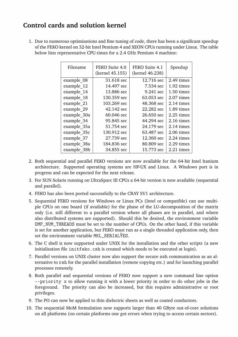
Control cards and solution kernel
1. Due to numerous optimisations and fine tuning of code, there has been a significant speedupof the FEKO kernel on 32-bit Intel Pentium 4 and XEON CPUs running under Linux. The tablebelow lists representative CPU-times for a 2.4 GHz Pentium 4 machine:
Filename FEKO Suite 4.0 FEKO Suite 4.1 Speedup(kernel 45.155) (kernel 46.238)
example_08 31.618 sec 12.716 sec 2.49 timesexample_12 14.497 sec 7.534 sec 1.92 timesexample_14 13.886 sec 9.241 sec 1.50 timesexample_18 130.359 sec 63.053 sec 2.07 timesexample_21 103.269 sec 48.368 sec 2.14 timesexample_29 42.142 sec 22.282 sec 1.89 timesexample_30a 60.046 sec 26.650 sec 2.25 timesexample_34 95.845 sec 44.294 sec 2.16 timesexample_35a 51.754 sec 24.179 sec 2.14 timesexample_35c 130.912 sec 63.487 sec 2.06 timesexample_37 27.739 sec 12.360 sec 2.24 timesexample_38a 184.836 sec 80.809 sec 2.29 timesexample_38b 34.855 sec 15.773 sec 2.21 times
2. Both sequential and parallel FEKO versions are now available for the 64-bit Intel Itaniumarchitecture. Supported operating systems are HP-UX and Linux. A Windows port is inprogress and can be expected for the next release.
3. For SUN Solaris running on UltraSparc III CPUs a 64-bit version is now available (sequentialand parallel).
4. FEKO has also been ported successfully to the CRAY SV1 architecture.
5. Sequential FEKO versions for Windows or Linux PCs (Intel or compatible) can use multi-ple CPUs on one board (if available) for the phase of the LU-decomposition of the matrixonly (i.e. still different to a parallel version where all phases are in parallel, and wherealso distributed systems are supported). Should this be desired, the environment variableOMP_NUM_THREADS must be set to the number of CPUs. On the other hand, if this variableis set for another application, but FEKO must run as a single threaded application only, thenset the environment variable MKL_SERIALYES.
6. The C shell is now supported under UNIX for the installation and the other scripts (a newinitialisation file initfeko.csh is created which needs to be executed at login).
7. Parallel versions on UNIX cluster now also support the secure ssh communication as an al-ternative to rsh for the parallel installation (remote copying etc.) and for launching parallelprocesses remotely.
8. Both parallel and sequential versions of FEKO now support a new command line option--priority x to allow running it with a lower priority in order to do other jobs in theforeground. The priority can also be increased, but this requires administrative or rootprivileges.
9. The PO can now be applied to thin dielectric sheets as well as coated conductors.
10. The sequential MoM formulation now supports larger than 40 GByte out-of-core solutionson all platforms (on certain platforms one got errors when trying to access certain sectors).

11. Improved checks of the geometry, thus more errors in the input file (like overlapping ele-ments) can be detected.
12. Numerous improvements to the UTD ray-tracing routines for double diffraction.
13. When using the exact Skin effect formulation for wires then the evaluation of Bessel func-tions became instable when the wire radius is very thick as compared to the penetrationdepth. In such cases FEKO now switches to an asymptotic expression.
14. In connection with the Green’s function for planar multilayered media, now improved ac-curacy for far field computations very close to the critical angle, and also more accuratesolutions for very thick layers (several thousands of wavelengths thick, i.e. for optical stud-ies).
15. Though not recommended (for efficiency and speed reasons), FEKO solutions including out-of-core solutions are now working on mapped network drives under Windows. This did workin most cases already before, but certain system configurations resulted in errors (often notreproducible).
16. For parallel versions improvements regarding both stability and speed in the underlyingcommunication protocol by using the latest MPI libraries for the various platforms.
17. More robust error treatment for parallel versions due to a FEKO native parallel error handler.
18. L4 card now allows a switch to remove all L4 loads.
Support components
1. OPTFEKO now supports an option --resume to resume an optimisation process that hasbeen stopped, provided that the *.sta and *.bat files are still available. (For example,if the previous optimisation has been stopped by pressing <Ctrl><C> or due to a powerfailure.) For Windows/DOS this option must follow right after the filename.
2. The NEARFIELD_VALUES aim function in OPTFEKO has been extended such that one canalso optimise the fields directly (i.e. switch the normalisation off). The number of near fieldpoints has also been increased from 1000 to 2000.
3. The aim function RADIATION_PATTERN has been extended such that one can also optimisefor gain/directivity in dB, and such that in addition to minimising the deviation from aspecific aim pattern, one can now also specify a band with min/max values.
4. A new aim function RESONANCE allows optimising an antenna / circuit / resonator to reso-nance (i.e. imaginary part of the input impedance should be zero).
5. Both OPTFEKO and TIMEFEKO now support of the option -np x to use the parallel versionof FEKO during optimisation or time domain analysis.
6. The adaptive frequency interpolation technique now gives a percent progress indication atthe end of each completed subinterval. Certain parameters for this technique have alsobeen adjusted to reduce the number of required frequency sample points for very wide bandresults.
User interface
1. New multi-platform version of EDITFEKO available.

2. EDITFEKO can now also launch OPTFEKO and TIMEFEKO with a simplified dialog to controlthe command line options for all the other components.
3. WinFEKO now uses scrollable panels such that one can use a smaller window or lowerresolution.
4. The UTD ray data has been divided into separate categories for near and far fields allowingseparate selection in WinFEKO.
5. Numerous small bugs in the parsing of the output file have been fixed, for example verysmall values (written as, for example, 1.23456-789) are now parsed correctly. It is also nowquicker for large files.
6. WinFEKO and GraphFEKO now also extract the mass density of the media from the *.outfile when calculating SAR.
7. The colour selection for labels has been improved such that a much larger number of labelswill have unique colours. In particular the mapping of colours to labels can now be assignedarbitrarily by the user (in the legend just double click on a colour box and a window willappear where the colour can be re-assigned).
8. Animation in WinFEKO has been improved to be less sensitive to other windows coveringthe render area during the preparation of the animation.
9. Many fixes regarding printing, animation and cut-planes in WinFEKO.
10. GraphFEKO now supports two new arithmetic functions (a) to take the inverse or the of thevalues of the specified series and (b) to take 10 to the power of the series value. In additionit can create a zero series (from which one can determine an arbitrary constant value byspecifying an offset) and a linear series (where the left axis is set equal to the bottom axis— this can be scaled to any slope).
11. When using adaptive frequency interpolation and specifying a minimum frequency stepping,one might end up with a solution that has not converged in a certain frequency interval. Thisis now indicated in GraphFEKO.
12. FEMAP no longer requires a default file which needs to be updated with each new versionof FEMAP.
Release Notes for FEKO Suite 4.0December 2002
(Changes since FEKO Suite 3.2)
FEKO Suite 4.0 is an update release that contains many improvements and extensions and a betaversion of the new multi-platform EDITFEKO on UNIX platforms. This version also supports FEKOLITE instead of the old demo version. (Limits are slightly higher for FEKO LITE than what theywere for the demo mode.)
Note that you will require a new licence file that supports Suite 4.0 in order to activate it. This licencefile is also valid for FEKO Suite 3.1.2 and later in case you need to use an earlier version of FEKO.
The most important new features are listed below. Many small bug fixes and additions as well asperformance improvements have been included in addition to the listed items.
Geometry cards and preprocessing
1. The NASTRAN import filter (see the IN card) has been extended to allow importing 16character wide grid points. In addition variables are supported for the label selecting fieldsat the IN card.
2. The PM card has been extended to allow specifying up to 26 internal mesh points to allowconnecting with other structures.
3. Fixed bugs with respect to the number of nodes in processing PM and PY cards.
4. The PH card now supports angles larger than 90 around the hole.
5. Fixed bugs leading to a floating point exception or an infinite loop in treatment of polygonalplates.
Control cards and solution kernel
1. The planar Green’s function now also supports the AR card. In addition, it uses an asymptotictechnique to calculate the near fields at large distances.
2. It is now also possible to export the four potentials ~A, ~F , ∇ϕ and ∇ψ directly.
3. The AP card now supports apertures calculated using negative angles.
4. The PO ray tracing is much more efficient and various small bugs have been fixed. Multiplereflections are now fully supported. (Visibility between certain regions can be specified withthe VS card.) Electrically thick dielectric/magnetic coatings of conducting surfaces are alsoallowed.
5. Non-radiating transmission lines now support losses.
6. For Windows the FEKO kernel has been compiled to make use of the Pentium IV instructionset if this is available. This will yield speed improvements of up to 50% on these machines.
7. The FEKO–CableMod interface now supports adaptive frequency sampling.
8. The FMM (fast multipole method) has been significantly improved, there is now a MLFMMvariant (multilevel).

Support components
1. Improved error checking for all components.
2. In addition to the penalty function which limits the range of the optimisation variables,OPTFEKO can now enforce that the parameters never move outside the specified limits.
3. When optimising an average reflection coefficient, it is possible to specify a minimum reflec-tion coefficient such that OPTFEKO will not continuously improve certain reflection coeffi-cients further and further while others are still much larger than the desired value.
User interface
1. WinFEKO and GraphFEKO now process UNIX *.out files without converting them firstwhich allows processing data from large out files that previously was not possible.
2. Paths containing spaces should now be fully supported.
3. WinFEKO and GraphFEKO now correctly extract the conductivity from the *.out file whencalculating SAR.
4. New line arithmetics tools in GraphFEKO support converting between real and imaginaryparts and magnitude and phase.
5. WinFEKO allows a simple way to configure and start the parallel version of FEKO on Win-dows.