ferrari noninvasive
TRANSCRIPT
8/8/2019 Ferrari Noninvasive
http://slidepdf.com/reader/full/ferrari-noninvasive 1/6
ISPCS 2008 – International IEEE Symposium on Precision Clock
Synchronization for Measurement, Control and CommunicationAnn Arbor, Michigan, September 22–26, 2008
Non invasive Time Synchronization for ZigBee Wireless Sensor Networks
P. Ferrari1, A. Flammini
1, D. Marioli
1, E. Sisinni
1, A. Taroni
2
1University of Brescia – DEA – Brescia – Via Branze,38 – 25123 – Italy2Carlo Cattaneo University, Castellanza (VA) – C.so Matteotti,22 – 21053 – Italy
Email: [email protected], Tel.+390303715445 Fax. +39030380014
Abstract –A precise time synchronization is essential in many
Wireless Sensor Networking applications, e.g. in order to correlateobservations of the same event from different sites or to efficiently
share the wireless channel. Generally, wireless sensors are designed having in mind low cost and low power. In the past, several
protocols have been suggested, each one with its pros and cons,aiming at the maximization of the accuracy vs. consumption ratio.
However, their performance have been generally tested on particular hardware setup and with proprietary communication
protocols. In this paper we present a non invasive implementation of
a synchronization protocol over a full ZigBee-compliant platform. Experimental evaluation on real prototypes has been performed inorder to ensure feasibility and verify performances. Our approach
preserves compatibility with this emerging standard still offering synchronization error on the order of few μ s if synchronization
procedure is executed every 4 s.
Keywords – Wireless Sensor Neworking, Time synchronization, Distributed system
I. INTRODUCTION
ZigBee (ZB) [1] is an emerging standard for Wireless
Sensor Networks (WSNs). It targets low distance, low data
rate, low power consumption and low cost applications;
according to standard nomenclature, it implements a Low
Rate–Wireless Personal Area Network (LR-WPAN).
However, there is a lot of confusion around what the term ZB
really describes and its name has been often misused (for
instance in [2] the term is misused, since it only refers to an
IEEE802.15.4-compliant hardware platform). ZB defines
upper layers (network and application) of the ISO protocol
reference model. On the contrary, in regards to the physical
and data link ones, it relies over another standard, the well
accepted IEEE802.15.4 [3], which offers a gross transfer rate
of 250 kbps in the 2.4 GHz ISM unlicensed band. Although
ZB is designed for event-based applications, it can take
advantage from sensors clock synchronization, in order togive an unique time reference to all measurements and
events. However, synchronization procedure should be
simple, in order to not waste power, and it should preserve
compatibility with the available ZB stacks, including the so-
called ZB-processors [4].
In the past several protocols have been proposed and used
for time synchronization in wired and wireless networks.
Mill’s Network Time Protocol (NTP) [5] has been widely
used in the Internet for decades. However, traditional
synchronization schemes are not suitable for use in WSNs
due to the specific requirements of those networks in terms of
precision (that must be high) and cost (nodes have typically
limited power, computational and storage resources). In fact,
most of the protocols designed for wired environments
exchange several huge messages and also need to store them
(for statistical processing). For this reason, solutions like the
IEEE1588v2 or even the IEEE802.1AS [6], that has been also
proposed for wireless audio video broadcasting, must be
discarded. On the other hand, their basic principle (i.e.
pairwise message exchanges within a hierarchicalmaster/slave structure) and the concept of transparent clock
can be borrowed and usefully adopted in multi hop WSNs.
Recently, a significant amount of research on time
synchronization for wireless sensor has been published [7,8].
Taking advantage from the well-known TPSN (Timing-sync
Protocol for Sensor Networks) protocol [9], we propose a non
invasive modification that preserves all the features of
standard ZB stack and allows to reach time synchronization
on the order of few μs without decreasing power efficiency.
The rest of this paper is structured as follows. In Section II
we present an overview of ZB architecture and the time
synchronization from the ZB point of view. After describing
our implementation in Section III, we present someexperimental results in Section IV. Finally, in section V some
concluding remarks are reported.
II. ZIGBEE AND TIME SYNCHRONIZATION
Key feature of ZB is the capability of handling both single
(star topology) and multi hop (cluster tree and mesh
topologies) networks. The cluster-tree is a hierarchical
topology, probably the most interesting solution of this
standard. In this case the network consists of clusters, each
having a “router” as a cluster head and multiple devices as
leaf nodes. A “PAN coordinator” initiates the network andserves as the root. The network is formed by parent-child
relationships, where new nodes associate as children with the
existing coordinators. This well-defined structure simplifies
multi-hop routing and allows energy saving; each node
maintains synchronization of data exchanges with its parent
coordinator only. As a matter of fact, two different kinds of
devices can participate in ZB-WSNs: Full Function Devices
(FFDs) and Reduced Function Devices (RFDs). They
differentiate on the basis of capabilities and, thus, on the
resources needed to operate. An RFD does not have routing
978-1-4244-2275-3/08/$25.00 ©2008 IEEE
Authorized licensed use limited to: UNIVERSITY OF DELAWARE LIBRARY. Downloaded on January 20, 2009 at 19:40 from IEEE Xplore. Restrictions apply.
8/8/2019 Ferrari Noninvasive
http://slidepdf.com/reader/full/ferrari-noninvasive 2/6
capabilities and can act as end node only. It can only
communicate with its parent, i.e. the node that allowed it to
join the network. On the contrary, an FFD has routing
capabilities and can be configured as the WSN coordinator.
According to this distinction, ZB implements three types of
logical devices: coordinator (must be an FFD), router (must
be an FFD) and end device (may be an FFD or an RFD).
In order to reduce latency and packet losses, the current
ZB standard requires FFDs to be always on, which in practice
means that if they are battery-powered their lifetime is on the
order of a few days. On the contrary, RFD are optimized for
low power consumption and are allowed to enter in the deep
sleep modality offered by the hardware, as better explained in
the superframe description that follows. It is evident that
mesh topology allows only FFDs and it is not a power
efficient solution
As we previously said, ZB has been optimized for single
sporadic event notification, as suggested by the adoption of
CSMA/CA (Carrier Sense Multiple Access with Collision
Avoidance) as medium access protocol.
In regard to time synchronization, it is based on theexchange of particular packets, called Beacon, that FFDs may
emit on a regular basis. However, only star and tree networks
may use beacon-oriented communications, but many
commercially available stacks do not fully support this
feature. In addition, Beacons do not use CSMA/CA and a lot
of burden must be done in order to avoid collisions between
them or with data frames. As previously stated, each cluster is
managed by one coordinator (i.e. Zigbee Router - FFD),
which generates periodic Beacon frames to synchronize its
child nodes (belonging to its cluster). Since many nodes of
different clusters may occupy the same operating space, their
transmissions must be accurately scheduled to not overlap.
Obviously, there is a tradeoff with respect to the network scalability, since this approach obliges each node to collect
information about all its neighbors and their parents. This in
turn means that each node must compile such a database,
greatly affecting memory resource requirements.
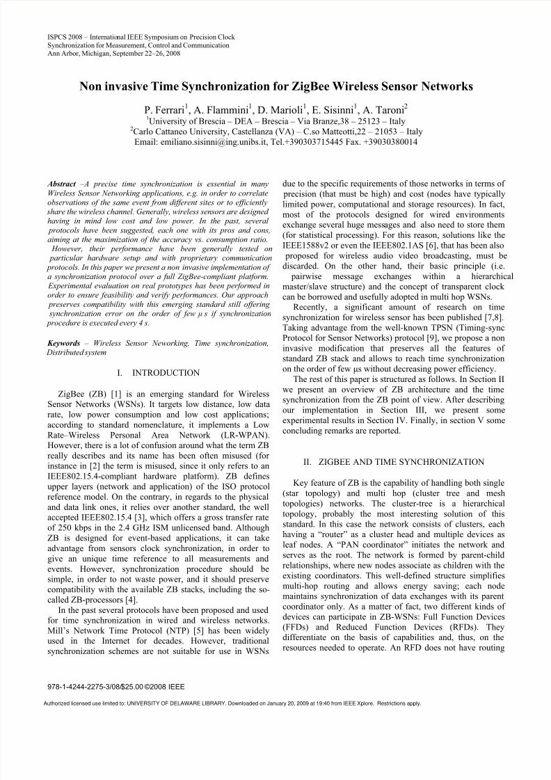
The ZB standard suggests to divide the time into different
non overlapping timeslots each one corresponding to the
superframe active portion of that node (see Fig.1).
WPAN
Coordinator
(FFD)
Cluster Head
(FFD)
Level k
End Device
(RFD)
Level k+1
Superframe
(Level k)
Superframe
(Level k+1)
Active portion of the
superframe
Coordinator
Beacon
Cluster Head
Beacon
Fig. 1. Beacon scheduling under ZB.
In fact, the activity of a beacon-enabled node is organized
into regular repetitive patterns (superframes) that initiate with
the Beacon transmission. The time between two successive
Beacons is divided into an active and a sleep portion of
variable lengths. In the latter, nodes are not allowed to
communicate. A node that wants to join the network must
choose the time collocation of the active portion of its
superframe structure with any suitable algorithm able to
avoid overlapping. Nevertheless, the standard do not
specifically address this aspect. If there are no free non-
overlapping time slots, the device shall not transmit Beacons
and shall operate on the network as an end device (i.e. it
cannot route packets).
III. THE PROPOSED APPROACH
Authors’ basic idea is to completely avoid the use of
Beacons still ensuring that all nodes share the same sense of
time in order to improve power efficiency; also the traditional
“listen-before-talk” strategy of the CSMA/CA protocol
should be preserved. In particular, we want to permit node
synchronization without using a complex and rigid structure
as the superframe time organization. This approach lowers
the node protocol complexity since no particular scheduling
algorithm must be employed and it is not needed to acquireinformation about neighbors. It must be also remembered that
beacons are handled at the MAC level of the protocol and we
do not want to operate at intermediate levels of the stack to be
implementation independent. As better explained in the
following, we only access the application layer of the
protocol stack (no matter who made it) and exploit a minimal
software integration to furnish low level timestamping, when
this feature in not already provided.
A. The TPSN protocol
What we suggest is a modified implementation of the
well-known TPSN [9] protocol in order to be fullycompatible with ZB without increasing consumption. TPSN
is a traditional sender-receiver based synchronization
protocol that uses a tree to organize the clock hierarchy. In
the original proposal, there is a level discovery phase and an
actual synchronization phase. The first step of the algorithm
is to create a hierarchical topology in the network. Every
node is assigned a level in this hierarchical structure. The
basic hypothesis underlying this phase is that a node
belonging to level k+1 can communicate with at least one
node belonging to level k . Only one node is assigned to level
“0”, which it is called the “root node”.
The level discovery phase is initiated by the root sending a
level discovery packet which contains the identity and thelevel of the sender. The immediate neighbors (i.e. MAC
neighbors) of the root node receive this packet and assign
themselves a level “1”. After establishing their own level,
they broadcast a new level discovery packet. This process is
continued and eventually every node in the network is
assigned a level. After a node obtains his level, it discards
any such future packets. This makes sure that no flooding
congestion takes place in this phase.
Once the hierarchical structure has been established, the
root node initiates the second stage of the algorithm, the so
Authorized licensed use limited to: UNIVERSITY OF DELAWARE LIBRARY. Downloaded on January 20, 2009 at 19:40 from IEEE Xplore. Restrictions apply.
8/8/2019 Ferrari Noninvasive
http://slidepdf.com/reader/full/ferrari-noninvasive 3/6
called synchronization phase. In this phase, a node belonging
to level k+1 synchronizes to a node belonging to level k .Eventually every node is synchronized to the root node and
we achieve network-wide time synchronization. The main
improvement suggested by the original TPSN protocol is the
adoption of a MAC level timestamping, that allows to
precisely mark the begin of a transmission and its reception.
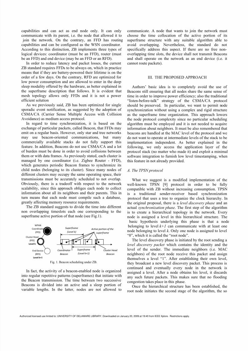
In our implementation the first phase is superfluous, since
the root is always the coordinator and hierarchical clock
structure coincides with the cluster tree-topology [10].
Synchronization among nodes of level k (closer to the root)
and level k+1 is achieved by means of a pair wise packets
exchange, called “Synchronization Pulse” and
“ Acknowledgement ” packet, respectively, as shown in Fig.2.
Level k+2 Level k+1 Level k
Time
T1,k+1
T2,k
T3,k
T4,k+1
T1,k+2
T2,k+1
T3,k+1
T4,k+2
Synchronization
Pulse
Acknowledgement
WPAN
Coordinator
(FFD)
Cluster Head
(FFD)
Level k
End Device
(RFD)
Level k+2
Cluster Head(FFD)
Level k+1
Fig. 2. Two-way message exchanges between nodes of different
hierarchical levels.
B. Implementation within the ZigBee protocol
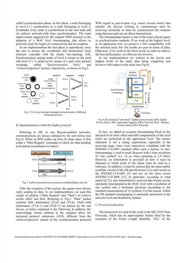
Referring to ZB, in non Beacon-enabled networks,
communications are always initiated by the end device (see
Fig.3). When an RFD wakes up from its deep sleep, it firstsends a “Data Request” command to check for data pending
at its parent (coordinator or router).
FFD - Level k+1 RFD - Level k+2
Data Request
ACK
ACK
DATA
(T1,k+1)(T2,k)
(T3,k) (T4,k+1)
Fig. 3. Indirect transmission in nonbeacon-enabled ZigBee network.
After the reception of this packet, the parent must always
reply sending its data. In our implementation, we used this
couple of packets (“Data Request” and “Data”) to retrieve
clocks offset and drift. Referring to Fig.3, “Data” packet
contains both information (T2,k) and (T3,k), while both
information (T1,k+1) and (T4,k+1) are known by the end
device, as better explained in the following. In addition, the
acknowledge frames defined in the standard allow for
increased protocol robustness (ACK, different from the
Acknowledgement packet of the synchronization protocol).
With regard to peer-to-peer (e.g. router toward router) data
transfer, the devices wishing to communicate must be
receiving constantly or must be synchronized (for instance
using Beacon) and can use direct transmission.
The timestamping feature is one of the most critical aspect
in synchronization methods. If we work at the highest level,
as an application tool, we preserve a full compatibility with
the selected stack, but the results are poor in terms of jitter.
Otherwise, if we work at the lower levels in order to achieve
the best performance, we often are too invasive.
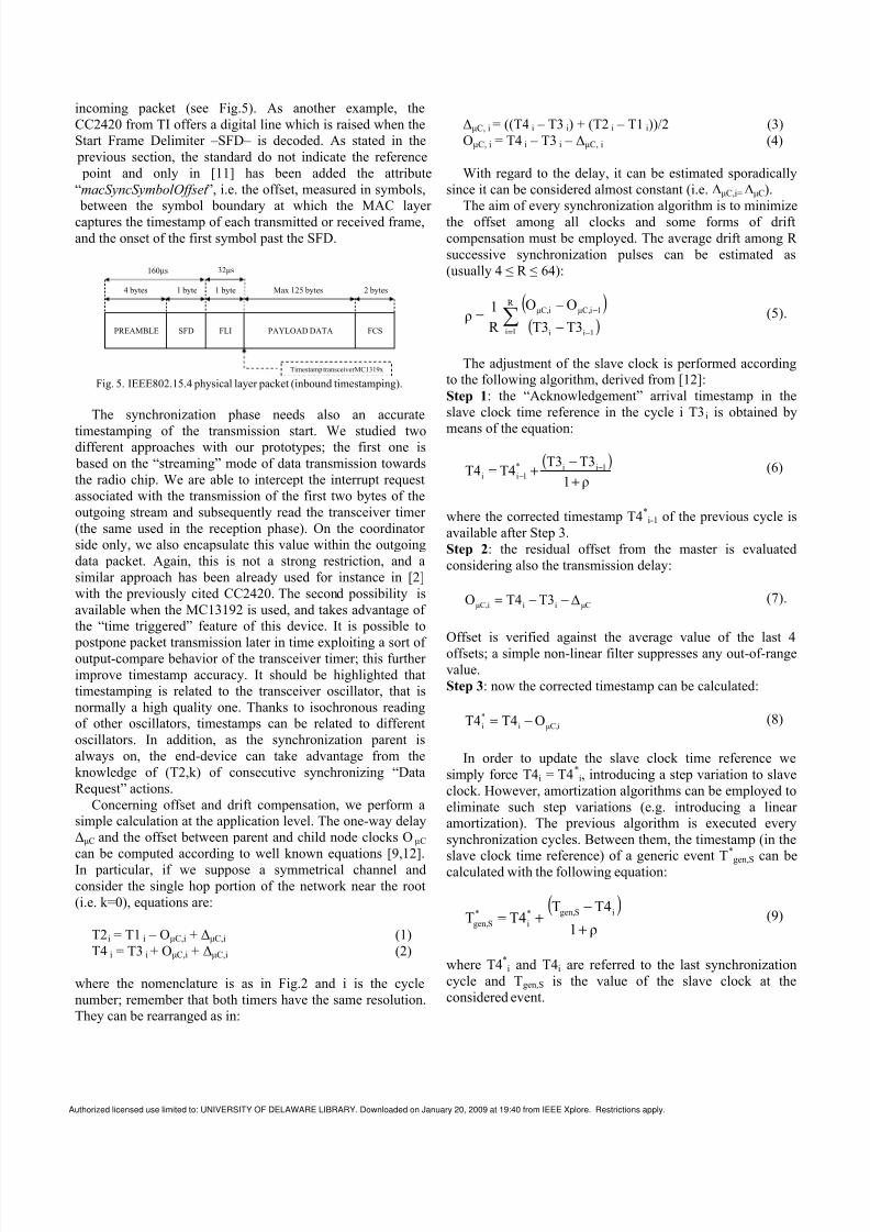
In our implementation we worked at the lowest and
highest levels of the stack, thus being completely non
invasive with respect to the stack (see Fig.4).
Synchro
End Point ZDO
APS
NWK
MAC
PHY
Timestamping
S e c u r i t y
I E E E 8 0 2 . 1
5 . 4
Z I G B E E
Synchronization
“retrofitting”
Transceiver
Fig. 4.The proposed “retro fitted” ZigBee protocol stack (ZDO: Zigbee
Device Object, APS: Application Support, NWK: Network, MAC: Medium
Access Control, PHY: Physical).
In fact, we added an accurate timestamping block at the
physical level while offset and drift compensation of the local
clock are performed at the application level. The former statement is not a strong requirement, especially at the
receiving stage, since every transceiver compliant with the
IEEE802.15.4-2003 standard offers such a feature. In fact,
timestamping is used to track Beacons with a time resolution
of “one symbol” (i.e. 16 μs when operating at 2.4 GHz).
However, no information is provided on how it must be
obtained or which point of the frame must be used as a
reference. In addition, it must be noticed that the latest public
available version of the ZB specifications [1] is only based on
the IEEE802.15.4-2003 [3] and not on the more recent
IEEE802.15.4-2006 [11]. In particular, according to what
stated in [11], also transmitted or received data frames can be
optionally timestamped at the MAC level with a resolution of one symbol and a minimum precision (according to the
standard nomenclature) of 16 symbols. For this reason, within
the ZB standard timestamping is optionally performed at the
network level and disabled by default.
C. Practical realization
The transceiver we used in this work is the MC13192 from
Freescale, which has an input-capture feature fired by the
reception of the Frame Length Identifier –FLI– of the
Authorized licensed use limited to: UNIVERSITY OF DELAWARE LIBRARY. Downloaded on January 20, 2009 at 19:40 from IEEE Xplore. Restrictions apply.
8/8/2019 Ferrari Noninvasive
http://slidepdf.com/reader/full/ferrari-noninvasive 4/6
incoming packet (see Fig.5). As another example, the
CC2420 from TI offers a digital line which is raised when the
Start Frame Delimiter –SFD– is decoded. As stated in the
previous section, the standard do not indicate the reference
point and only in [11] has been added the attribute
“macSyncSymbolOffset ”, i.e. the offset, measured in symbols,
between the symbol boundary at which the MAC layer
captures the timestamp of each transmitted or received frame,
and the onset of the first symbol past the SFD.
32μs160μs
2 bytesMax 125 bytes1 byte1 byte
PREAMBLE SFD FLI PAYLOAD DATA FCS
Timestamp transceiverMC1319x
4 bytes
Fig. 5. IEEE802.15.4 physical layer packet (inbound timestamping).
The synchronization phase needs also an accurate
timestamping of the transmission start. We studied twodifferent approaches with our prototypes; the first one is
based on the “streaming” mode of data transmission towards
the radio chip. We are able to intercept the interrupt request
associated with the transmission of the first two bytes of the
outgoing stream and subsequently read the transceiver timer
(the same used in the reception phase). On the coordinator
side only, we also encapsulate this value within the outgoing
data packet. Again, this is not a strong restriction, and a
similar approach has been already used for instance in [2]
with the previously cited CC2420. The second possibility is
available when the MC13192 is used, and takes advantage of
the “time triggered” feature of this device. It is possible to
postpone packet transmission later in time exploiting a sort of output-compare behavior of the transceiver timer; this further
improve timestamp accuracy. It should be highlighted that
timestamping is related to the transceiver oscillator, that is
normally a high quality one. Thanks to isochronous reading
of other oscillators, timestamps can be related to different
oscillators. In addition, as the synchronization parent is
always on, the end-device can take advantage from the
knowledge of (T2,k) of consecutive synchronizing “Data
Request” actions.
Concerning offset and drift compensation, we perform a
simple calculation at the application level. The one-way delay
ΔμC and the offset between parent and child node clocks O μC
can be computed according to well known equations [9,12].
In particular, if we suppose a symmetrical channel and
consider the single hop portion of the network near the root
(i.e. k=0), equations are:
T2i = T1 i – OμC,i + ΔμC,i (1)
T4 i = T3 i + OμC,i + ΔμC,i (2)
where the nomenclature is as in Fig.2 and i is the cycle
number; remember that both timers have the same resolution.
They can be rearranged as in:
ΔμC, i = ((T4 i – T3 i) + (T2 i – T1 i))/2 (3)
OμC, i = T4 i – T3 i – ΔμC, i (4)
With regard to the delay, it can be estimated sporadically
since it can be considered almost constant (i.e. ΔμC,i=ΔμC).
The aim of every synchronization algorithm is to minimize
the offset among all clocks and some forms of drift
compensation must be employed. The average drift among R
successive synchronization pulses can be estimated as
(usually 4 ≤ R ≤ 64):
( )( )∑
= −
−
−
−
=
R
1i 1ii
1iμC,iμC,
T3T3
OO
R
1ρ (5).
The adjustment of the slave clock is performed according
to the following algorithm, derived from [12]:
Step 1: the “Acknowledgement” arrival timestamp in the
slave clock time reference in the cycle i T3 i is obtained by
means of the equation:
( )ρ1
T3T3T4T4 1ii*
1ii+
−+=
−
−
(6)
where the corrected timestamp T4*i-1 of the previous cycle is
available after Step 3.
Step 2: the residual offset from the master is evaluated
considering also the transmission delay:
μCiiiμC, ΔT3T4O −−= (7).
Offset is verified against the average value of the last 4
offsets; a simple non-linear filter suppresses any out-of-range
value.
Step 3: now the corrected timestamp can be calculated:
iμC,i
*
i OT4T4 −= (8)
In order to update the slave clock time reference we
simply force T4i = T4*i, introducing a step variation to slave
clock. However, amortization algorithms can be employed to
eliminate such step variations (e.g. introducing a linear amortization). The previous algorithm is executed every
synchronization cycles. Between them, the timestamp (in theslave clock time reference) of a generic event T*
gen,Scan be
calculated with the following equation:
( )ρ1
T4TT4T
iSgen,*
i
*
Sgen,+
−
+= (9)
where T4*i and T4i are referred to the last synchronization
cycle and Tgen,S is the value of the slave clock at the
considered event.
Authorized licensed use limited to: UNIVERSITY OF DELAWARE LIBRARY. Downloaded on January 20, 2009 at 19:40 from IEEE Xplore. Restrictions apply.

8/8/2019 Ferrari Noninvasive
http://slidepdf.com/reader/full/ferrari-noninvasive 5/6
IV. EXPERIMENTAL RESULTS
Preliminary tests have been conducted with two nodes
implementing the BeeKit [13] stack from Freescale. One of them was configured as the PAN coordinator, the other as an
end device. As previously stated, all timestamps were based
on the timer of the radio device, clocked at 62.5kHz. Thischoice is dictated by low power considerations and,
obviously, it doesn’t offer a very high resolution. (Currently,
attempts to use the smallest available time grain of 0.5μs are
being carried on).
A passive sniffer showing the packet duration in air has been implemented using the CC2420 transceiver (a digital
line shows the actual message timestamp point, i.e. the SFD).
It has been used to estimate the so called outbound andinbound latency, with the first one being the propagation time
between the clock timestamp point and the communication
medium for outbound messages and the second one the propagation time between the communication medium and
the clock timestamp point for inbound messages.
In regards to outgoing messages, a digital line (PTA5_ZCfor coordinator and PTA5_ZED for end device in Fig.6 and
Fig.7) toggles when timestamping occurs and the delay is
measured with respect to the sniffer signal (SFD in Fig.6 andFig.7).
ΔOUT
Synchronization Pulse
Acknowledge (IEEE802.15.4)
Fig. 6. “Synchronization Pulse” message properties.
ΔOUT
Acknowledge
Acknowledge (IEEE802.15.4)
Fig. 7. “Acknowledge” message properties.
An Agilent logic state analyzer HP1690A has been used
obtaining that this delay lasts about ΔOUT=306μs for both kind
of messages. On the contrary, for incoming messages it has
been supposed that latency is ΔIN=32μs, since the hardware
timestamping occurs after the reception of the FLI (see
Fig.5).
In order to verify algorithm implementation, the node
itself has been used to compute the one-way delay ΔμC. It has been obtained ΔμC=21 clock ticks, i.e.
(ΔμC)·TCK ≤ΔOUT+ΔIN<(ΔμC+1)·TCK where TCK =16μs is the
clock tick duration. In other words, 336μs≤ΔOUT+ΔIN<352μs,
in accordance with theoretical estimation. It has been alsoestimated the channel asymmetry, that is on the order of 0.2μs and thus can be neglected. Attention must be paid if we
want to synchronize nodes compliant with ZB using different
solutions, since they can use different timestamping reference
point as previously said.
Some additional measurements have been performed using
a three-nodes WSN, made up of a coordinator and two singlehop childes. The two nodes start together with completely
unsynchronized clocks and are deployed in an environment
with an almost constant temperature. The absolute
synchronization error has been estimated comparing theoffset error as computed in Eq.(7). If a sync period of
TSYNC=4 s is used, the maximum deviation between the twonodes is on the order of 32 μs, as expected being the timer
resolution equal to 16 μs. In Fig.8 it has been reported the
offset distribution over 256 consecutive synchronization
periods for both the nodes.
-30 -25 -20 -15 -10 -5 0 5 10 15 20 25 300
50
100
150
200
250
Offset [µs]
F r e q u e n c y
Max synchronization error
Node A
Node B
Fig. 8. Synchronization error of two nodes (A and B) with a
synchronization period of TSYNC=4s.
V. CONCLUSION
In this paper a non-invasive approach for synchronization
of ZB wireless networks has been proposed. Theimplemented algorithm exploits pairwise synchronization andcan be used as the basic building block to synchronize an
entire multi hop network. The main advantage of the
proposed approach is that it can be easily “retrofitted” on
every ZB compliant platform without increasing cost or
complexity. It works at the application level except for a
Authorized licensed use limited to: UNIVERSITY OF DELAWARE LIBRARY. Downloaded on January 20, 2009 at 19:40 from IEEE Xplore. Restrictions apply.

8/8/2019 Ferrari Noninvasive
http://slidepdf.com/reader/full/ferrari-noninvasive 6/6
small plugin that allows for MAC level timestamping. If a
sync interval of 4 s with a timer resolution of 16 μs is used
the maximum offset error between two nodes has been
experimentally evaluated to be on the order of 32 μs.
REFERENCES
[1] ZigBee Specification, ZigBee Document 053474r17, January 17, 2008,
ZigBee Alliance.
[2] D. Cox, E. Jovanov, A. Milenkovic, “Time synchronization for ZigBee
networks”, in Proc of SSST05, March 2005, pp. 135 – 138.[3] IEEE Std. 802.15.4-2003, Wireless Medium Access Control (MAC) and
Physical Layer (PHY) Specifications for LR-WPANs. IEEE Press. 2003
[4] STMicroelectronics SN260 (http://www.st.com/ stonline/ products/literature/ds/12972/sn260.htm), Texas Instruments CC2480
(http://focus.ti.com/ docs/ prod/ folders/print/cc2480a1.html).
[5] D. L. Mills, “Internet time synchronization: the network time protocol,”
IEEE Trans. On Communications, vol. 39, no. 10, pp. 1482–1493, Oct.
1991.[6] G.M. Garner, F. Feng, K. den Hollander, J. Hongkyu, K. Byungsuk, L.
Byoung-Joon, J. Tae-Chul, J.J. Joung, “IEEE 802.1 AVB and its
Application in Carrier-Grade Ethernet”, IEEE CommunicationsMagazine, vol.45, n.12, pp.126-134.
[7] F. Sivrikaya, B. Yener, “Time synchronization in sensor networks: Asurvey” IEEE Network, vol. 18, pp. 45–50, July 2004.
[8] B. Sundararaman, U. Buy, A. D. Kshemkalyani, “Clock synchronization
in wireless sensor networks: A survey,” Ad-Hoc Networks, vol. 3, pp.
281–323, May 2005.[9] S. Ganeriwal, R. Kumar, M.B. Srivastava, “Timing-sync protocol for
sensor networks”, in Proc. of SenSys03, Nov. 2003, pp. 138-149.
[10] P.Yadav, N. Yadav, S. Varma, “Cluster based hierarchical wirelesssensor networks (CHWSN) and time synchronization in CHWSN”, Proc.
Of ISCIT '07, Oct. 2007, pp. 1149-1154.
[11] IEEE Std. 802.15.4-2006, Wireless Medium Access Control (MAC) andPhysical Layer (PHY) Specifications for LR-WPANs. IEEE Press. 2006
[12]P. Ferrari, A. Flammini, D. Marioli, A. Taroni, "IEEE 1588-based
Synchronization System for a Displacement Sensor Network", IEEETrans. Instrum. Meas., February, 2008, Vol. IM-57, N. 2, pp. 254-260.
[13] Online: http://www.freescale.com/