ferrofluid for alkaline flooding
TRANSCRIPT
8/13/2019 Ferrofluid for Alkaline Flooding
http://slidepdf.com/reader/full/ferrofluid-for-alkaline-flooding 1/7
SPE 131272
Application of Ferrofluid for Enhanced Surfactant Flooding in EORNikita Kothari, Bhavna Raina, Krishna Chandak, Venkat Iyer & Hrishikesh Mahajan, Maharashtra Institute ofTechnology, Pune
Copyright 2010, Society of Petroleum Engineers
This paper was prepared for presentation at the SPE EUROPEC/EAGE Annual Conference and Exhibition held in Barcelona, Spain, 14–17 June 2010.
This paper was selected for presentation by an SPE program committee following review of information contained in an abstract submitted by the author(s). Contents of the paper have not beenreviewed by the Society of Petroleum Engineers and are subject to correction by the author(s). The material does not necessarily reflect any position of the Society of Petroleum Engineers, itsofficers, or members. Electronic reproduction, distribution, or storage of any part of this paper without the written consent of the Society of Petroleum Engineers is prohibited. Permission toreproduce in print is restricted to an abstract of not more than 300 words; illustrations may not be copied. The abstract must contain conspicuous acknowledgment of SPE copyright.
Abstract:
Improved Oil Recovery (IOR), techniques offer prospects that enhance the displacement of oil from thereservoir, ultimately producing 30 to 60 percent, ormore, of the reservoir's original oil in place. The mostimportant criteria in IOR- Surfactant Flooding is todetermine if the interfacial tension (IFT) can bereduced enough to produce incremental oil.
One of the key recovery problems in oil-wet reservoir is overcoming the surface tension forcesthat tend to bind the oil to the rock. In water wetreservoirs, surface tension forces act to create bubblesof oil, which can block pore passages as the bubbleresists movement in the increased surface areaassociated with squeezing through the passages. Thesesurface tension forces are the primary reason whyreservoirs become increasingly impermeable to oil,relative to water, as the water saturation increases.
Ferrofluids are a special category of smartnano-materials, in particular magnetically controllablenanofluids. The ferromagnetic nano-particles arecoated with a surfactant to prevent their agglomeration.As a result of their composition, Ferrofluids possess a
unique combination of fluidity and the capability tointeract with a magnetic field. The addition of asurfactant will greatly reduce the Interfacial Tensionand in water-wet reservoirs, where oil globules areformed, ferrofluid shatters it. Also, as ferrofluid comesin contact with the reservoir fluid, it interacts with thecrude in the reservoir & due to the presence of dipolemoment, the reservoir fluid molecules align, thusreducing the resistance to the flow.
To sum up, reduction in Interfacial tension,thus reducing resistance to the flow, can be easily
achieved by making use of Ferrofluid-enhanced
surfactant. Oil can be made even more polar using
Ferrofluid which will act as a better solvent for thesurfactant.
Introduction:
Ferrofluid:
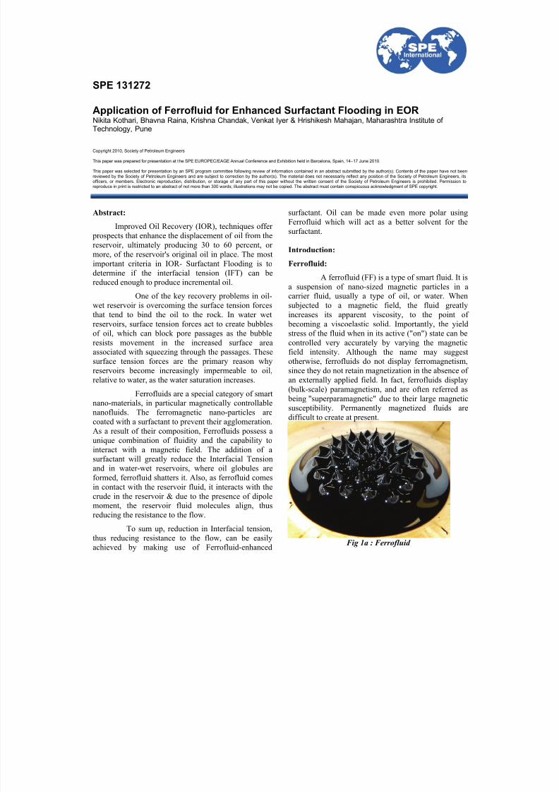
A ferrofluid (FF) is a type of smart fluid. It isa suspension of nano-sized magnetic particles in acarrier fluid, usually a type of oil, or water. Whensubjected to a magnetic field, the fluid greatlyincreases its apparent viscosity, to the point of
becoming a viscoelastic solid. Importantly, the yieldstress of the fluid when in its active ("on") state can becontrolled very accurately by varying the magneticfield intensity. Although the name may suggestotherwise, ferrofluids do not display ferromagnetism,since they do not retain magnetization in the absence ofan externally applied field. In fact, ferrofluids display(bulk-scale) paramagnetism, and are often referred as
being "superparamagnetic" due to their large magneticsusceptibility. Permanently magnetized fluids aredifficult to create at present.
Fig 1a : Ferrofluid
8/13/2019 Ferrofluid for Alkaline Flooding
http://slidepdf.com/reader/full/ferrofluid-for-alkaline-flooding 2/7
2 SPE 131272
Figure 1a shows a FF in a magnetic field showingnormal-field instability magnet beneath the dish whensubjected to a sufficiently strong vertical magneticfield, the surface spontaneously forms a regular patternof corrugations; this effect is known as the normal-field instability. The formation of the corrugations
increases the surface free energy and the gravitationalenergy of the liquid, but reduces the magnetic energy.The corrugations will only form above a criticalmagnetic field strength, when the reduction inmagnetic energy outweighs the increase in surface andgravitation energy terms. Ferrofluids have anexceptionally high magnetic susceptibility and thecritical magnetic field for the onset of the corrugationscan be realised by a small bar magnet.
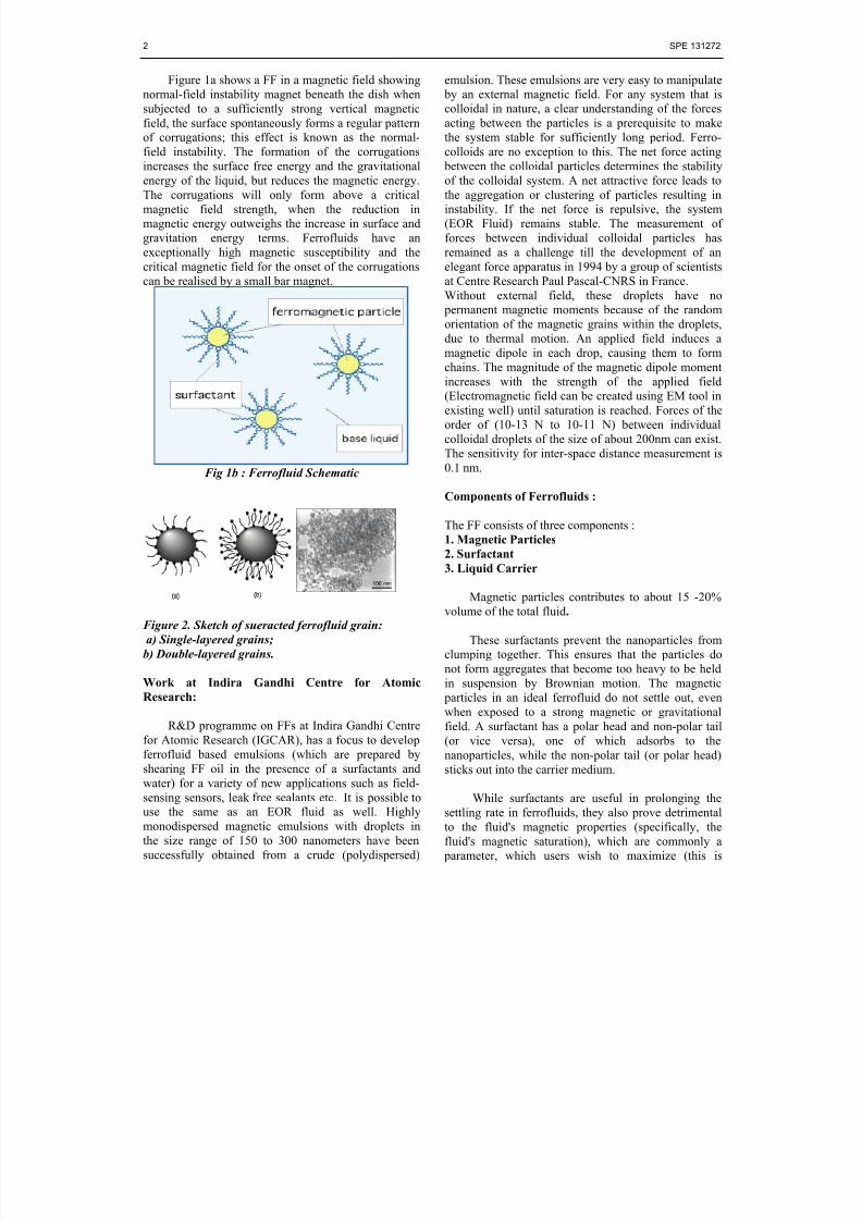
Fig 1b : Ferrofluid Schematic
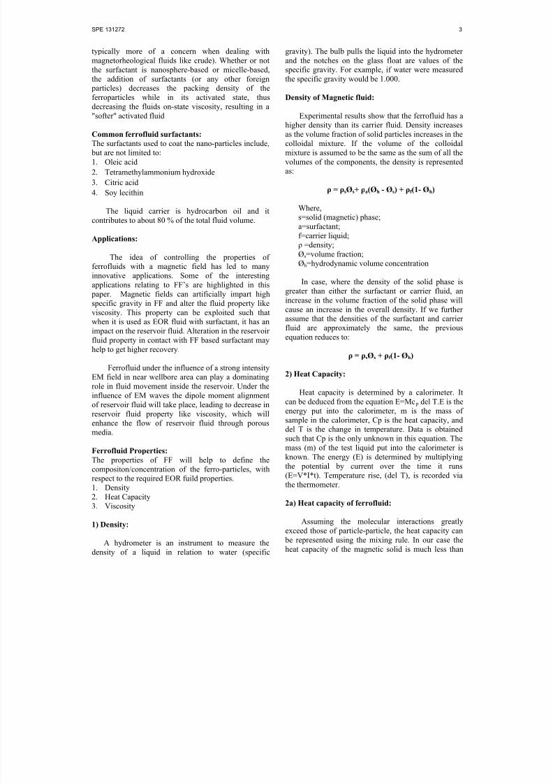
Figure 2. Sketch of sueracted ferrofluid grain:
a) Single-layered grains;
b) Double-layered grains.
Work at Indira Gandhi Centre for Atomic
Research:
R&D programme on FFs at Indira Gandhi Centrefor Atomic Research (IGCAR), has a focus to developferrofluid based emulsions (which are prepared byshearing FF oil in the presence of a surfactants andwater) for a variety of new applications such as field-sensing sensors, leak free sealants etc. It is possible touse the same as an EOR fluid as well. Highlymonodispersed magnetic emulsions with droplets in
the size range of 150 to 300 nanometers have beensuccessfully obtained from a crude (polydispersed)
emulsion. These emulsions are very easy to manipulate by an external magnetic field. For any system that iscolloidal in nature, a clear understanding of the forcesacting between the particles is a prerequisite to makethe system stable for sufficiently long period. Ferro-colloids are no exception to this. The net force acting
between the colloidal particles determines the stabilityof the colloidal system. A net attractive force leads tothe aggregation or clustering of particles resulting ininstability. If the net force is repulsive, the system(EOR Fluid) remains stable. The measurement offorces between individual colloidal particles hasremained as a challenge till the development of anelegant force apparatus in 1994 by a group of scientistsat Centre Research Paul Pascal-CNRS in France.Without external field, these droplets have no
permanent magnetic moments because of the randomorientation of the magnetic grains within the droplets,
due to thermal motion. An applied field induces amagnetic dipole in each drop, causing them to formchains. The magnitude of the magnetic dipole momentincreases with the strength of the applied field(Electromagnetic field can be created using EM tool inexisting well) until saturation is reached. Forces of theorder of (10-13 N to 10-11 N) between individualcolloidal droplets of the size of about 200nm can exist.The sensitivity for inter-space distance measurement is0.1 nm.
Components of Ferrofluids :
The FF consists of three components :1. Magnetic Particles
2. Surfactant
3. Liquid Carrier
Magnetic particles contributes to about 15 -20%volume of the total fluid.
These surfactants prevent the nanoparticles fromclumping together. This ensures that the particles do
not form aggregates that become too heavy to be heldin suspension by Brownian motion. The magnetic particles in an ideal ferrofluid do not settle out, evenwhen exposed to a strong magnetic or gravitationalfield. A surfactant has a polar head and non-polar tail(or vice versa), one of which adsorbs to thenanoparticles, while the non-polar tail (or polar head)sticks out into the carrier medium.
While surfactants are useful in prolonging thesettling rate in ferrofluids, they also prove detrimentalto the fluid's magnetic properties (specifically, the
fluid's magnetic saturation), which are commonly a parameter, which users wish to maximize (this is
8/13/2019 Ferrofluid for Alkaline Flooding
http://slidepdf.com/reader/full/ferrofluid-for-alkaline-flooding 3/7
SPE 131272 3
typically more of a concern when dealing withmagnetorheological fluids like crude). Whether or notthe surfactant is nanosphere-based or micelle-based,the addition of surfactants (or any other foreign
particles) decreases the packing density of theferroparticles while in its activated state, thus
decreasing the fluids on-state viscosity, resulting in a"softer" activated fluid
Common ferrofluid surfactants: The surfactants used to coat the nano-particles include,
but are not limited to:1. Oleic acid
2. Tetramethylammonium hydroxide
3. Citric acid
4. Soy lecithin
The liquid carrier is hydrocarbon oil and itcontributes to about 80 % of the total fluid volume.
Applications:
The idea of controlling the properties offerrofluids with a magnetic field has led to manyinnovative applications. Some of the interestingapplications relating to FF’s are highlighted in this
paper. Magnetic fields can artificially impart highspecific gravity in FF and alter the fluid property likeviscosity. This property can be exploited such that
when it is used as EOR fluid with surfactant, it has animpact on the reservoir fluid. Alteration in the reservoirfluid property in contact with FF based surfactant mayhelp to get higher recovery.
Ferrofluid under the influence of a strong intensityEM field in near wellbore area can play a dominatingrole in fluid movement inside the reservoir. Under theinfluence of EM waves the dipole moment alignmentof reservoir fluid will take place, leading to decrease inreservoir fluid property like viscosity, which willenhance the flow of reservoir fluid through porous
media.
Ferrofluid Properties:
The properties of FF will help to define thecompositon/concentration of the ferro-particles, withrespect to the required EOR fuild properties. 1. Density2. Heat Capacity3. Viscosity
1) Density:
A hydrometer is an instrument to measure thedensity of a liquid in relation to water (specific
gravity). The bulb pulls the liquid into the hydrometerand the notches on the glass float are values of thespecific gravity. For example, if water were measuredthe specific gravity would be 1.000.
Density of Magnetic fluid:
Experimental results show that the ferrofluid has ahigher density than its carrier fluid. Density increasesas the volume fraction of solid particles increases in thecolloidal mixture. If the volume of the colloidalmixture is assumed to be the same as the sum of all thevolumes of the components, the density is representedas:
ρ = ρsØs+ ρa(Øh - Øs) + ρf (1- Øh)
Where,
s=solid (magnetic) phase;a=surfactant;f=carrier liquid;ρ =density;Øs=volume fraction;Øh=hydrodynamic volume concentration
In case, where the density of the solid phase isgreater than either the surfactant or carrier fluid, anincrease in the volume fraction of the solid phase willcause an increase in the overall density. If we furtherassume that the densities of the surfactant and carrier
fluid are approximately the same, the previousequation reduces to:
ρ = ρsØs + ρf (1- Øh)
2) Heat Capacity:
Heat capacity is determined by a calorimeter. Itcan be deduced from the equation E=Mc p del T.E is theenergy put into the calorimeter, m is the mass ofsample in the calorimeter, Cp is the heat capacity, and
del T is the change in temperature. Data is obtainedsuch that Cp is the only unknown in this equation. Themass (m) of the test liquid put into the calorimeter isknown. The energy (E) is determined by multiplyingthe potential by current over the time it runs(E=V*I*t). Temperature rise, (del T), is recorded viathe thermometer.
2a) Heat capacity of ferrofluid:
Assuming the molecular interactions greatlyexceed those of particle-particle, the heat capacity can
be represented using the mixing rule. In our case theheat capacity of the magnetic solid is much less than
8/13/2019 Ferrofluid for Alkaline Flooding
http://slidepdf.com/reader/full/ferrofluid-for-alkaline-flooding 4/7
4 SPE 131272
that of the fluid or surfactant. Thus, an increase in massconcentration of the solid particles will cause theoverall heat capacity of the ferrofluid to decline.
C = CsØs+ Ca(Øh - Øs) + Cf (1- Øh)
3) Viscosity:
The viscosity of a magnetic fluid depends on thesolid fraction, the viscosity of the carrier fluid and theapplied magnetic field (orientation as well as force).For the determination without an applied magneticfield any standard viscometer can be used. In additionthe viscosity can be estimated using one of thefollowing formulas (from Rosensweig,Ferrohydrodynamics):
Viscosity estimation:
For small particle concentration:
η = η o*(1+2.5Ø)
For higher particle concentration:
η = η o*(1+aØ+b Ø2)
-1
Where,
a = -2.5 and b = (2.5 Øc -1)/ Øc2 where, Øc = 0.74
(Closed Package)
Cost of Ferrofluids :
The cost of ferrofluids can vary from over $30 per liter to half that depending upon the ferro particleconcentration.
Basic Concept:
The basic concept is to treat the entire process(surface and subsurface; exploration through the entirelife of the reservoir) as a single system to be optimized
and continually improved.
Downhole information and control could beavailable through higher EM field channels throughoutwell construction, completion, and production.
The basic concept of this approach is that theindustry develops the capability to fully monitor andcontrol the way fluids are moving through a reservoir.This is extremely challenging, but has hugeimplications on recovery. FF has capability to gettraced on application of EM waves, by observingvaration in the EM wave intensity.
To improve EOR recovery it is essential toimprove sweep efficiency. This will require significantimprovement in reservoir-scale surveillancetechnology and in our ability to interpret and make themeasurements. In some cases it will be possible toimprove the sweep efficiency by changing injection
and production rates; in other cases it will be necessaryto target unswept areas with infill or sidetrack wells.
Unfortunately, the observations that we canmake are not direct measurements of saturation, butrather are related to physical properties (e.g. pressure,temperature, impedance, electrical resistivity, andgravity) and it is necessary to interpret the changes in
physical properties in terms of the fluid-saturationchanges. Ferro-fluid can have a mojor impact toaccompalish the same.
These physical properties are converted tosaturations using a combination of empirical equations(e.g. Archie equation) and parameters based on coreanalysis (m, n, etc.). This empirical foundation limitsthe accuracy of this approach and our ability to managereservoirs. To interpret the observational data, we aregenerally forced to run a reservoir simulator, and in
parallel, compute the saturations changes based onobservations, and thereby infer fluid movements.Ideally this manual means of “inverting” the data toinfer the fluid distributions would be replaced with aFF tracker (Change in EM distribution within the
reservoir) that predicts fluid flow.
Alkaline-surfactant flooding:
Alkali flooding was a low-cost chemical flood because surfactant could be generated by in situreaction between alkali and naphthenic acids present incrude oil. However, it was difficult to keep theelectrolyte concentration at optimal conditions becausethe concentration of alkali required for propagationwas usually higher than the optimal salinity. It was
discovered that injection of a small amount of syntheticsurfactant with the alkali made it possible to have the process pass through the optimal conditions in situ. Inaddition, alkali tended to reduce the adsorption of thesynthetic surfactant and thus made it possible to injecta low surfactant concentration.
At present, ferrofluids (magnetic fluids), stabledispersions of magnetic materials in liquids, are widelyused systems in different applications includingtechnical, industrial and biomedical fields. Thestabilization of these fluids takes place after a single
layer of surfactants covers the surface of the magnetic particles, which is enough to avoid the particle
8/13/2019 Ferrofluid for Alkaline Flooding
http://slidepdf.com/reader/full/ferrofluid-for-alkaline-flooding 5/7
SPE 131272 5
aggregation in various external conditions includingmagnetic fields and temperature effects. The advantageof surfactant with FF over surfactant alone is that it can
be used for reservoir temperatue upto 140o deg. C.
Additionally it will assist to reduce the viscosity of thereservoir fluid. The addition of surfactants decreases
the packing density of the ferroparticles while in itsactivated state. This decreases the fluids on-stateviscosity, resulting in a "softer" activatedfluid.
Ferrofluid Enhanced Surfactant:
Stabilization of ferrofluids based on polar carriersis a more complicated problem, and a single surfactantlayer around the magnetic particles providing onlyrepulsion between particles in the fluids is not enough.Recently, methods of double sterical stabilization weredeveloped for several classes of polar carriers. The
technique implies that after the surfactant of one type isadsorbed on the particle surface through chemicaladsorption, the surfactant of the same or another type(depending on the adsorption properties) is adsorbedon the previous layer through physical adsorption.
Ferrofluid enhanced surfactant fluid:
A magnetic fluid, (MF) consists in chemicalstabilized and dispersed magnetic nanoparticles in acarrier liquid. Based on their complex characteristicsgiven by the magnetic component (magnetite stabilizedwith oleic acid) and the liquid carrier where this one isdispersed (hydrocarbons, especially oil compounds),there is the possibility to use them in separation
processes through extraction of oily compounds fromaqueous systems. This process consists in oilycomponent distribution between the liquid carrier ofthe ferrofluid and the aqueous phase.
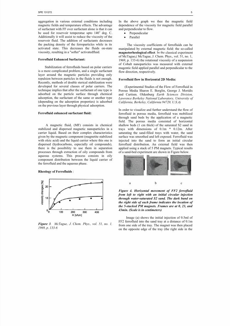
Rheology of Ferrofluids :
Figure 3. McTague, J. Chem. Phys., vol. 51, no. 1,1969, p. 133-6
In the above graph we thee the magnetic fielddependence of the viscosity for magnetic field paralleland perpendicular to flow.
• Perpendicular
• Parallel
The viscosity coefficients of ferrofluids can bemanipulated by external magnetic field: the so-calledmagnetorheological effect. In the classical experimentof McTague,( McTague, J. Chem. Phys., vol. 51, no. 1,1969, p. 133-6) the rotational viscosity of a suspensionof Cobalt nanoparticles was measured with externalmagentic field applied parallel and perpendicular to theflow direction, respectively.
Ferrofluid flow in Horizontal 2D Media:
(Experimental Studies of the Flow of Ferrofluid in
Porous Media Sharon E. Borglin, George J. Moridisand Curtism. Oldenburg Earth Sciences Division,
Lawrence Berkeley National Laboratory, University of
California, Berkeley, California 94720, U.S.A)
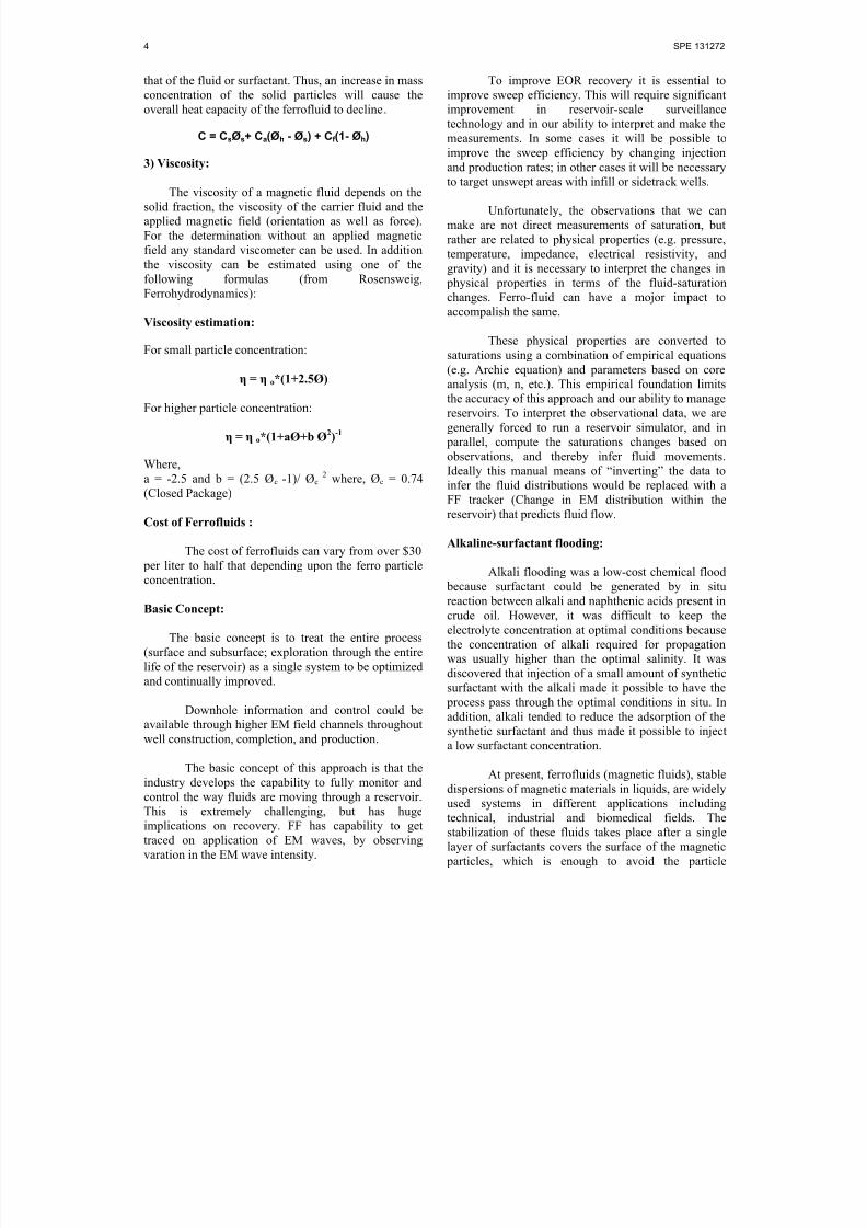
In order to visualize and further understand the flow offerrofluid in porous media, ferrofluid was mobilizedthrough sand beds by the application of a magneticfield. The porous media consisted of horizontalshallow beds (1 cm thick) of the saturated S2 sand intrays with dimensions of 0.1m * 0.12m. Aftersaturating the sand-filled trays with water, the sandsurface was smoothed and left exposed. Ferrofluid wasinjected into the sand to form an initial circularferrofluid distribution. An external field was thenapplied using a stack of 5 PM magnets. Typical resultsof a sand-bed experiment are shown in Figure below.
a b c
Figure 4. Horizontal movement of FF2 ferrofluid
from left to right with an initial circular injection
through water-saturated S2 sand. The dark band on
the right side of each frame indicates the location of
the 5-stacked PM magnets. Frames are at 0, 23, and
43min. (Scale is in centimeters)
Image (a) shows the initial injection of 0.5ml ofFF2 ferrofluid into the sand tray at a distance of 0.1m
from one side of the tray. The magnet was then placedon the opposite edge of the tray (the right side in the
8/13/2019 Ferrofluid for Alkaline Flooding
http://slidepdf.com/reader/full/ferrofluid-for-alkaline-flooding 6/7
6 SPE 131272
image) so that the center of the sand was aligned withthe magnetic pole. Images (b) and (c) depict theferrofluid distribution at 23 and 43min after injection.The ferrofluid initially follows a direct pathway towardthe center of the magnet. As the ferrofluid reaches theend of the tray, the magnet causes the ferrofluid to pool
in a semi-circle pattern.
Experiments with larger sand trays showed asimilar pattern of movement from distances of 0.25m.At these distances, the force on the ferrofluid issmaller, thus causing a decrease in the velocity of theferrofluid. Travel time for the 0.25m experiments is onthe order of 1 week. As the fluid approaches themagnet, the velocity increases due to the increasingmagnetic field strength and field gradient. Regardlessof the initial injection configuration of the ferrofluid,the end configuration is the same semi-circular shape,
which is controlled by the magnetic field.Ferrofluid flow in Horizontal 2D Media:
Properties of porous media used in the experiments:
Designation Porosity Hydraulic D10 (mm) Conductivity,K , (m/s)
S1 0.22 1:8 * 10−6 0.046S2 0.46 4:2 * 10−5 0.23S3 0.33 1:5 * 10−3 0.45S4 0.34 3:6 * 10−6 0.065
Movement of ferrofluid in a vertical cell filled
with water-saturated S3 sand was conducted to observethe effect of the magnetic field and gravity on themovement of a ferrofluid in porous media. The cellconsisted of two glass plates, 23 cm wide and 25 cmtall, separated by a 0.95 cm gap. The plates were sealedon three sides, and the top was left open. Using asyringe, the ferrofluid was injected into the unsealedtop of the cell, 20 cm from the magnet, as shown innext figure. The ferrofluid experienced bothgravitational and magnetic forces as it migrateddownward. In this case, magnetic forces dominated andthe final accumulation is a semi-circular pool, with a
slight but discernible asymmetry due to the effect ofgravity.
A vertical cell filled with a combination ofwater-saturated S3 and S4 sand was prepared toobserve the effect of permeability variation on the flowof ferrofluid.
The cell, same as the one described above, wasfilled with 15 cm of S3 sand, followed by a 3 cm layerof S4 sand, and topped by a 6 cm layer of S3 sand. The
band of S4 sand was placed between the ferrofluid
injection point and the magnet. The movement of
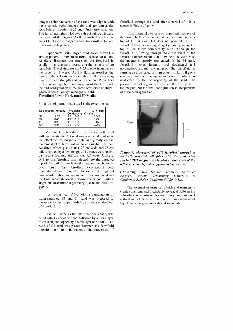
ferrofluid through the sand after a period of 4 h isshown in Figure 5 below.
This frame shows several important features ofthe flow. The first feature is that the ferrofluid pools ontop of the S4 sand, but does not penetrate it. The
ferrofluid then begins migrating by moving along thetop of the lower permeability sand. Although theferrofluid is flowing through the entire width of theferrofluid-darkened band, the flow near the vicinity ofthe magnet is greatly accelerated. In the S4 sand,ferrofluid moves laterally and downward andaccumulates around the magnet. The ferrofluid isforming an arc-shaped configuration, similar to the oneobserved in the homogeneous system, which isunaffected by the heterogeneity of the sand. The
presence of heterogeneities affected the flow path tothe magnet, but the final configuration is independent
of these heterogeneities.
Figure 5. Movement of FF2 ferrofluid through a
vertically oriented cell filled with S3 sand. Five
stacked PM1 magnets are located on the center of the
left side. Time elapsed is approximately 75min.
(Oldenburg Earth Sciences Division, Lawrence
Berkeley National Laboratory, University of
California, Berkeley, California 94720, U.S.A)
The potential of using ferrofluids and magnets tocreate consistent and predictable spherical bulbs in thesubsurface is significant because many environmentalrestoration activities require precise emplacement ofliquids in heterogeneous soils and sediments.

8/13/2019 Ferrofluid for Alkaline Flooding
http://slidepdf.com/reader/full/ferrofluid-for-alkaline-flooding 7/7
SPE 131272 7
References:
1. J. Philip, C.B.Rao, B.Raj, “An optical probe forqualitative/quantitative evaluation of defects inferromagnetic materials” Patents 186620 &186574.
2. Machado, A.L.C. Petrobras Internal Report
Cenpes/Diger/Seteq. CT 060/96.19963. Biao, W. & Lijian, D. "Paraffin Characteristics of
Paraffinic Crude Oils in China and the Methods ofParaffin Removal and Inhibition", paper SPE29954 presented at the 1995, Beijing, 1995
4. Burguer, E. Striegler, T.K."Studies of ParaffinDeposition in the Trans Alaska Pipeline". JPT,1986(6).
Figure 6. Flow of ferrofluid through a cell filled with
a combination of S3 and S4 sands. Five stacked PM1
magnets are located on the left side of the cell. Time
elapsed is 4 h.
5. Castellan, G. W.: Physical Chemistry, AddsonWesley Publishing Company, and Inc. 1971.
6. S. Rocha. N.O: "Efeito do Campo Magnetico NaDeposicao de Parafinas Na Explotacao do
Petroleo" M.Sc Thesis presented at FederalUniversity' of Rio de Janeiro (Dept of Chemistry),June. 1997.
The experiments described here are aimed atinvestigating the potential for controlling theemplacement of ferrofluid in subsurface porous media.To accomplish this, the behavior of ferrofluid wasobserved in the lab in real porous media systems. Thefollowing three conclusions can be drawn:
7. Donaldson, J. D. "The Application of MagneticDevices to Control Scale". Tube International.1988, 39
8. Baker, S.B., Judd. S.J. "Magnetic Amelioration ofScale Formation", Wat. Res. Vol. 30, No. 2 pp247-260.
1) Permanent magnets create a predictable pressuregradient in a magnetic fluid that leads to fluid flow,
2) Ferrofluid can be held in porous media in predictable final configurations, which arecontrolled solely by the magnetic field and are
unaffected by the flow pathway, initial injectionshape, or permeability of the porous medium,
9. Burguer, E. Striegler, T.K."Studies of ParaffinDeposition in the Trans Alaska Pipeline". JPT,1986(6).
10. Vieira, L.C. Petrobras Internal ReportCenpes/Diger/Seteq 047/96.1996
3) Ferrofluid exhibits only limited retention effects inthe advancing front during flow through sandy
porous media.
11. Fifth Latin American and Caribbean PetroleumEngineering Conference and Exhibition held in Riode Janeiro, Brazil, 30 August-3 September 1997,and Presentation.
The development of this technology would providea valuable tool for controlling liquid emplacementthrough the strong holding forces of the magnet in thesubsurface.
12. “Magnetic fluids and Applications Handbook”(B.Berkovski, Ed.), Beggel House, New York,1996.
13. Jordan, A. et al., J. Mag. Mag. Mater. 225, 118(2001).
Summary:
14. Vékás, L., Bica, D., Raşa, M., Balau, O., Potencz,I., Gheorghe, D., in “Micro and nanostructures”• Applicable for viscous reservoir fluid (10-500cp)
compared to conventional range of oil viscosityused in surfactant flooding.
15. (D. Dascalu et al., Eds.), pp.127-157, Ed.Academiei Romane, Bucharest, 2001.
16. Experimental Studies of the Flow of Ferrofluid inPorous Media Sharon E. Borglin, George J.Moridis and Curtism. Oldenburg Earth Sciences
Division, Lawrence Berkeley National Laboratory,
University of California, Berkeley, California
94720, U.S.A.
• Fluid flow can be traced and steered which willhelp in increasing accuracy of displacementefficiency calculation.
• Have Better Sweep Efficiency when compared tosurfactant flooding.
• It can be used to obtain petrophysical data of thereservoir.
17. Vékás, L., Raşa, M., Bica, D., J. Colloid InterfaceSci. 231, 247 (2000).
18. Bica, D., Vékás, L., Avdeev, M.V., Balasoiu, M.,Marinică, O., Stoian, F.D., Susan-Resiga.