festoon & conductor systems - hubbellelectrical_systems/.catalogues/.industrialsolutions/... ·...
TRANSCRIPT

FEST
OO
N &
CO
ND
UC
TOR
SYS
TEM
S
www.hubbellonline.com/wiring
A HUBBELL COMPANY
®
®
FESTOON & CONDUCTOR SYSTEMS
Product PageConductor Bars, Mounts and Accessories 2-10T-Track Festoon Lock ‘N Roll for Wire Rope 11-14C-Rail 15-18T-Track 19-23

FESTOO
N &
CO
ND
UC
TOR
SYSTEMS
Page
2 FESTOON & CONDUCTOR SYSTEMS
®
HUBBELL CANADA LP www.hubbellonline.com/wiring
DESIGN & CONSTRUCTION
CONDUCTOR BARS:All INVERTED V-BAR and UNIVERSAL 8-BAR Conductor bar sections are roll formed from galvanized steel or electrolytic copper. These systems are amply sized and proportioned to carry the specifi ed current without overheating. Internal joint connections assure full current carrying capacity without interfering with the free travel of the sliding collector contact shoes.
The standard insulating cover has a maximum temperature rating of 163°F (73°C). A high temperature insulation is available for a maximum temperature rating of 280°F (137°C).
CONDUCTOR JOINTS:The joints for these systems consist of two connector pins made of plated steel for the galvanize steel conductor bar or electrolytic copper for the copper conductor bar. The connector pins are knurled to provide suffi cient current carrying capacity and mechanical strength. The joint is designed to automatically align the conductor bar sections during installation.
CONDUCTOR SUPPORTS:The standard hangers are a snap-in design made from nylon or polycarbonate. The maximum temperature rating is 400°F (204°C). Anchor hangers are available to control the movement of the conductor bar. They must be used on systems less than 30 feet long., at all transfer sections and runs to control expansion and contraction fl ow.
CONDUCTOR COLLECTORS:Collector assemblies are offered in either single or double shoes types providing a continuous current carrying capacity of 40 amperes to 200 amperes. The contact shoes are supported by an insulating support that is spring loaded by an arm and body mechanism. All collectors are supplied with copper/graphite contacts for speeds up to 900 feet per minute on the INVERTED V-BAR and UNIVERSAL 8-BAR systems. For faster travel speeds, consult the factory.
NOTE: Current ratings are based on ambient temperature of 86°F (30°C).
The INVERTED V-BAR systems offer superior collector tracking capabilities especially at higher speeds since the “V” shaped metal guides the collector contact shoes rather than the insulating cover as with all 8-Bar systems.
The INVERTED V-BAR systems can be mounted for bottom entry or side entry of the collector contact shoes.
INVERTED V-BAR systems are recommended for side entry (lateral mounted) systems over 8-Bar systems or systems with fl at contact surfaces. Counter-balanced collectors are not required with the INVERTED V-BAR systems. The inward spring pressure on the contact shoe against the metal “V” contact surface fi ghts off the downward gravitational pull to provide more uniform contact show wear.
The UNIVERSAL 8-BAR systems may be used interchangeably with other 1” bottom entry 8-bar systems.
ADVANTAGES
The Conductor Electrifi cation System shall consist of thermoplastic enclosed conductor bar with mechanically tensioned collectors as manufactured by Gleason Reel Corporation.
The systems shall have a voltage rating of ( ) Volts A.C. or D.C. ( ) Volts and have a continuous current capacity of ( ) Amperes per pole. When used as a Crane and Hoist Electrifi cation System, the system shall be rated at ( ) Amperes for continuous service and ( ) Amperes for intermittent service. The full current carrying capacity of the system shall be maintained throughout.
The system shall permit longitude movement of the conductor bars in order to allow for unequal thermal expansion and contraction.
The system shall consist of standardized, interchangeable conductor bars (sections), power feeds, end caps, joint covers and collectors as called for in the plans.
TYPICAL SPECIFICATIONS
Polycarbonate snap-in hangers provide an extra level of insulation as well as a rigid support for the conductor sections.
TYPICAL APPLICATIONS:• Overhead Cranes
• Monorails
• Traveling Robots
• Aircraft Hanger Doors
• AS/RS Systems
The sections shall be made from roll formed galvanized steel or electrolytic copper and shall have a continuous “V” - groove, in the center, running the entire length. Conductors of this design shall be capable of carrying a current of 90 amperes and 110 amperes for steel sections and 250 amperes and 350 amperes for copper sections continuously without overheating. The sections shall be insulated with a thermoplastic cover rated for ambient temperatures to 163°F (73°C).
The type of the conductor will be either 8-Bar or V-Bar confi gurations as called for in the plans.
The collectors shall consist of a lubricant impregnated contact shoe, mechanically supported by an insulating support assembly that is spring loaded by an arm and body mechanism.
Collector assemblies shall be mounted on a 1” square mounting post and allow for 3” collector spacing without staggering. The collector contact shoes shall have the unique concave shape for 8-Bar systems or an inverted “V” shape for V-Bar systems.

FEST
OO
N &
CO
ND
UC
TOR
SYS
TEM
S
Page
3FESTOON & CONDUCTOR SYSTEMS
www.hubbellonline.com/wiring
A HUBBELL COMPANY
®
®
CONDUCTOR SECTIONSFOR 90, 110, 250 OR 350 AMP SYSTEMS
SPECIAL APPLICATIONSConsult the factory for information and pricing on the following:
1. Curved conductor sections
2. Corrosion resistant - stainless steel conductors are available
CONDUCTOR SECTIONSComplete 10’ (3028mm) long sections include two knurled connector pins and 163°F (73°C) rated thermoplastic insulating cover.
TEMPERATURE CONSIDERATIONSA high temperature insulating cover rated for 280°F (137°C) is also available To order, add the suffi x “HT” to the CAT. number.
CAT. NO.
CONTINUOUS CURRENT RATING
INTERMITTENT CURRENT RATING
CONDUCTOR MATERIAL
LENGTHft
WEIGHTlbs
V-90A 90 Ampere 135 Ampere Galv. Steel 10’ (3048mm) 4.5 (2.07 kg)
V-110A 110 Ampere 165 Ampere Galv. Steel 10’ (3048mm) 5.5 (2.50 kg)
V-250AL 250 Ampere 375 Ampere Copper / Steel 10’ (3048mm) 6.5 (2.95 kg)
V-350A 350 Ampere 525 Ampere Copper 10’ (3048mm) 7.1 (3.22 kg)
INVERTED V-BAR
CAT. NO. CONTINUOUS CURRENT RATING
INTERMITTENT CURRENT RATING
CONDUCTOR MATERIAL
LENGTHft
WEIGHTlbs
8-90A 90 Ampere 135 Ampere Galv. Steel 10’ (3048mm) 4.5 (2.07 kg)
8-110A 110 Ampere 165 Ampere Galv. Steel 10’ (3048mm) 5.5 (2.50 kg)
8-250AL 250 Ampere 375 Ampere Copper / Steel 10’ (3048mm) 6.5 (2.95 kg)
8-350A 350 Ampere 525 Ampere Copper 10’ (3048mm) 7.1 (3.22 kg)
UNIVERSAL 8-BAR

FESTOO
N &
CO
ND
UC
TOR
SYSTEMS
Page
4 FESTOON & CONDUCTOR SYSTEMS
®
HUBBELL CANADA LP www.hubbellonline.com/wiring
CONDUCTOR SECTIONSFOR 90, 110, 250 OR 350 AMP SYSTEMS
CONDUCTION SUPPORTSThermoplastic snap-in type hangers and anchor hangers provide for an additional level of insulation as well as rigid support. of the conductor sections.
An anchor hanger should be used on systems less than 30’ (9m) in length, at all transfer points/interlocks and where the conductor movement must be controlled or restricted.
Steel type hangers are also available.
Determine if the System is to be Side Entry (Lateral Mount) or Bottom Entry (Vertical Mount) and consult the Mounting Table (Right).
NOTE:Expansion sections must be staggered when conductor spacing is less than 3” (76mm).
*V-BAR is recommended on all Side Entry Systems.
CAT. NO. CONTINUOUS CURRENT RATING
INTERMITTENT CURRENT RATING
CONDUCTOR MATERIAL
LENGTHft
WEIGHTlbsV-BAR 8-BAR
V-90E 8-90E 90 Ampere 135 Ampere Galv. Steel 10’ (3048mm) 6.8 (3.1 kg)
V-110E 8-110E 110 Ampere 165 Ampere Galv. Steel 10’ (3048mm) 9.5 (4.3 kg)
V-250EL 8-250EL 250 Ampere 375 Ampere Copper / Steel 10’ (3048mm) 10.5 (4.8 kg)
V-350E 8-350E 350 Ampere 525 Ampere Copper 10’ (3048mm) 12.5 (5.7 kg)
SYSTEM MOUNTING V-BAR 8-BAR90 Amp Side Entry* 4’ (1220)90 Amp Bottom Entry 5’ (1220) 5’ (1525) 110 Amp Side Entry* 5’ (1525)110 Amp Bottom Entry 5’ (1525) 5’ (1525) 250 Amp Side Entry* 4’ (1220) 250 Amp Bottom Entry 5’ (1220) 5’ (1525) 350 Amp Side Entry* 4’ (1220) 350 Amp Bottom Entry 5’ (1220) 5’ (1525)
INVERTED V-BAR and UNIVERSAL 8-BAR EXPANSION SECTIONS
CONDUCTOR MATERIAL
COEF. OF LINEAR EXPANSION PER °F
(inches)
LINEAR EXPANSION PER 100’ RUN PER 100°F
TEMPERATURE CHANGE
Galv. Steel and Stainless Steel .000007 .84”
Copper .000009 1.08”
EXPANSION CONSIDERATIONS
NOTE:V-BAR and 8-BAR Expansion Sections have one 1.5” gap. Therefore, for every 100°F temperature change, install the expansion section as follows:
1. Galvanized Steel and Stainless Steel Conductors - Every 180’ (55m) ex: 1” center of 360’ (110m) run.
2. Copper Conductors - Every 140’ (43m).
3. All Systems - At building expansions.

FEST
OO
N &
CO
ND
UC
TOR
SYS
TEM
S
Page
5FESTOON & CONDUCTOR SYSTEMS
www.hubbellonline.com/wiring
A HUBBELL COMPANY
®
®
V-BAR CONDUCTOR ACCESSORIESFOR 90, 110, 250 OR 350 AMP SYSTEMS
CAT. NO. SYSTEM WEIGHT lbsV-90EPG for 90 amp system 1.50 (.68 kg)V-110EPG for 110 amp system 2.00 (.91 kg)V-225EPG for 250 amp system 2.00 (.91 kg)V-350EPG for 350 amp system 2.70 (1.22 kg)
CAT. NO. DESCRIPTION WEIGHT lbs
V-T Used to draw two conductor sections together (all systems) 2.8 (1.3 kg)
Connector Tool
Pick-Up Guide Assembly
CAT. NO. DESCRIPTION WEIGHT lbs
V-TCMolded plastic caps in lieu of end caps at transfer points (interlocks)
along the conductor run (all systems).10 (.04 kg)
Transfer Caps
CAT. NO. DESCRIPTION WEIGHT lbsV-JC 160°F (71°c) Orange (Standard)* .02 (.01 kg)
V-JCHT 280°F (137°C) Yellow for High Temp * .02 (.01 kg)V-JC-G Green for Ground Bar .02 (.01 kg)
* Insulating joint covers are fi eld installed over each joint to guard against accidental contact. One joint cover is required with each conductor section.
Joint Coverfor Inverted V-Bar Systems
CAT. NO. DESCRIPTION WEIGHT lbsV-90PF 110 ampere (for 90 & 110 amp sys) .33 (.15 kg)
V-350PF 350 ampere (for 250 & 350 amp sys) 1.25 (.57 kg)
Power-Feed Assemblyfor Inverted V-Bar Systems
CAT. NO. DESCRIPTION WEIGHT lbsV-H Single Non-Metallic Snap-in (all sys) .11 (.05 kg)
V-SH Single Steel Bolt-on (all sys) .20 (.09 kg)
Hanger Assembliesfor Inverted V-Bar Systems
Non-metallic guide with 19” (.5m) conductor bar, polycarbonate hangers and a transfer cap for guiding collector assemblies onto the conductor system after traveling free air.
CAT. NO. DESCRIPTION WEIGHT lbsV-90IJ for 90 amp system .04 (.02 kg)V-110IJ for 110 amp system .04 (.02 kg)
Used to interrupt power and isolate an area of the system.
End Capsfor Inverted V-Bar Systems
Anchor Hanger Assembliesfor Inverted V-Bar Systems
Isolation Piece
CAT. NO. DESCRIPTION WEIGHT lbs
V-HA Non-Metallic Snap-in w/ Nylon Drive Rivet (all sys) .12 (.05 kg)
Anchor Hangers should be used on all systems less than 30’ (9m) in length, at all transfer points / interlocks and where the conductor movement must be controlled or restricted.
CAT. NO. DESCRIPTION WEIGHT lbs
V-EC fi ts over exposed ends of conductor (all sys) .04 (.02 kg)

FESTOO
N &
CO
ND
UC
TOR
SYSTEMS
Page
6 FESTOON & CONDUCTOR SYSTEMS
®
HUBBELL CANADA LP www.hubbellonline.com/wiring
8-BAR CONDUCTOR ACCESSORIESFOR 90, 110, 250 OR 350 AMP SYSTEMS
CAT. NO. SYSTEM WEIGHT lbs8-90EPG for 90 amp system 1.50 (.68 kg)8-110EPG for 110 amp system 2.00 (.91 kg)8-250EPG for 250 amp system 2.00 (.91 kg)8-350EPG for 350 amp system 2.70 (1.22 kg)
CAT. NO. DESCRIPTION WEIGHT lbs
8-T Used to draw two conductor sections together (all systems) 2.8 (1.3 kg)
Connector Tool
Pick-Up Guide Assembly
CAT. NO. DESCRIPTION WEIGHT lbs
8-TCMolded plastic caps in lieu of end caps at transfer points (interlocks)
along the conductor run (all systems).10 (.04 kg)
Transfer Caps
CAT. NO. DESCRIPTION WEIGHT lbs8-JC 160°F (71°c) Orange (Standard)* .02 (.01 kg)
8-JCHT 280°F (137°C) Yellow for High Temp * .02 (.01 kg)8-JC-G Green for Ground Bar .02 (.01 kg)
* Insulating joint covers are fi eld installed over each joint to guard against accidental contact. One joint cover is required with each conductor section.
Joint Coverfor Universal 8-Bar Systems
CAT. NO. DESCRIPTION WEIGHT lbs8-90PF 110 ampere (for 90 & 110 amp sys) .30 (.14 kg)8-250PF 250 ampere (for 250 amp sys) .53 (.24 kg)8-350PF 350 ampere (for 350 amp sys) 1.40 (.64 kg)
Power-Feed Assemblyfor Universal 8-Bar Systems
CAT. NO. DESCRIPTION WEIGHT lbs8-H Single Non-Metallic Snap-in (all sys) .11 (.05 kg)
8-SPH Single Spring Steel (all sys) .04 (.02 kg)
Hanger Assembliesfor Universal 8-Bar Systems
Non-metallic guide with 19” (.5m) conductor bar, polycarbonate hangers and a transfer cap for guiding collector assemblies onto the conductor system after traveling free air.
CAT. NO. DESCRIPTION WEIGHT lbs8-90IPK for 90 amp system .04 (.02 kg)8-110IPK for 110 amp system .04 (.02 kg)
Used to interrupt power and isolate an area of the system.
End Capsfor Universal 8-Bar Systems
Anchor Hanger Assembliesfor Universal 8-Bar Systems
Isolation Piece
CAT. NO. DESCRIPTION WEIGHT lbs
8-HA Non-Metallic Snap-in w/ Nylon Drive Rivet (all sys) .12 (.06 kg)
Anchor Hangers should be used on all systems less than 30’ (9m) in length, at all transfer points / interlocks and where the conductor movement must be controlled or restricted.
CAT. NO. DESCRIPTION WEIGHT lbs
8-EC fi ts over exposed ends of conductor (all sys) .04 (.02 kg)

FEST
OO
N &
CO
ND
UC
TOR
SYS
TEM
S
Page
7FESTOON & CONDUCTOR SYSTEMS
www.hubbellonline.com/wiring
A HUBBELL COMPANY
®
®
MOUNTING BRACKETS
CAT. NO. X-DIMENSION WEIGHT lbsBK-W15 11¼” (286mm) 1.25 (.57 kg)BK-W18 14¼” (362mm) 1.50 (.68 kg)BK-W21 17¼” (438mm) 1.75 (.80 kg)BK-W24 20¼” (514mm) 2.15 (.98 kg)
Nomenclature of Mounting Brackets
BK = Bracket
OVERALL LENGTH IN INCHES
FLANGE THICKNESS FOR CLAMP ON
FLANGE MOUNTING BRACKETS (Not Used
With Web Mounting)A = .50”B = .75”C = 1.0”D = 1.25”
STYLE OF MOUNTING F = Top Flange MountW = Web Mount L = Web Mount Side Entry
BK - F 18 A
Mainline / Top Running Crane Applications-Web Mounting (Bottom Entry Systems)
Monorail / Underhung Crane Applications-Flange Mounting (Bottom Entry Systems)-Weld-on Type or Clamp-on Type
Side Entry Systems-Web Mounting Bracket (Side Entry Systems)
NOTE: Hangers are ordered separately.
BK-F18A with V-H Hangers
CAT. NO. X-DIMENSION WEIGHT lbsBK-F18 18” (457mm) 1.50 (.68 kg)BK-F21 21” (533mm) 1.75 (.80 kg)BK-F24 24” (610mm) 2.00 (.91 kg)
NOTE: Hangers are ordered separately.
CAT. NO. No. CONDUCTORS WEIGHT lbsBK-L4 4 (1.5” spacing) 2.00 (.91 kg)
BK-L3-2 3 (2.0” spacing) 2.00 (.91 kg)BK-L4-2 4 (2.0” spacing) 2.70 (1.22 kg)
BK-L4
2.0” Spacing 1.5” Spacing
“X”

FESTOO
N &
CO
ND
UC
TOR
SYSTEMS
Page
8 FESTOON & CONDUCTOR SYSTEMS
®
HUBBELL CANADA LP www.hubbellonline.com/wiring
COLLECTORSFOR 90, 110, 250 OR 350 AMP SYSTEMS
DESCRIPTIONSTANDARD
V-BAR 8-BARCOMPLETE SINGLE SHOE COLLECTORSMinimum Spacing Side-By-SideMinimum Spacing Staggered
40 Amp Bottom Entry (Vertical Mount)100 Amp Bottom Entry (Vertical Mount)40 Amp Side Entry (Lateral Mount)100 Amp Side Entry (Lateral Mount)
2.0” (51mm) 1.5” (38mm)
V-40SCV-100SCV-40SC
V-100SC
2.0” (51mm) 1.5” (38mm)
C-40SCC-100SC
NoneNone
COMPLETE DOUBLE SHOE COLLECTORSMinimum Spacing Side-By-Side
80 Amp Bottom Entry (Vertical Mount)200 Amp Bottom Entry (Vertical Mount)80 Amp Side Entry (Lateral Mount)200 Amp Side Entry (Lateral Mount)
2.0” (51mm)
V-80STCV-200STCV-80STC
V-200STC
2.0” (51mm)
C-80STCC-200STC
NoneNone
COLLECTOR HEADS (Shoe, Holder, Clevis & Pigtail Assy)
40 Amp100 Amp
V-40SCH-1V-100SCH-1
C-40SCH-1C-100SCH-1
CONTACT SHOES40 Amp & 100 Amp (4-3/4” long) V-100CS-1 C-100CS-1CONTACT SHOE HOLDERS C-VCSH-6 C-CSH-6
COLLECTOR EXTENSION SPRINGS C-SCS C-SCS
COLLECTOR ARM CASTINGS C-SCA C-SCACOLLECTOR MOUNTING POSTS1” Square Bar Welded to Mounting Plate
All Collectors#C-CMP
40 Amp V-Bar Collector AssemblyV-40SC
40 Amp 8-Bar Collector AssemblyC-40SC
80 Amp Tandem 8-Bar Collector AssemblyC-80STC
100 Amp V-Bar Collector AssemblyV-100SC
80 Amp Tandem V-Bar Collector AssemblyV-80STC
100 Amp 8-Bar Collector AssemblyC-100SC

FEST
OO
N &
CO
ND
UC
TOR
SYS
TEM
S
Page
9FESTOON & CONDUCTOR SYSTEMS
www.hubbellonline.com/wiring
A HUBBELL COMPANY
®
®
ENGINEERING DATA
1. VOLTAGE DROP CALCULATIONSA. Single Phase - A.C. Voltage Drop = 2 x Amps x Zac x distance in feet from power feed.
B. Three Phase - A.C. Voltage Drop = 1.732 x Amps x Zac x distance in feet from power feed.
C. Direct Current Voltage Drop = 2 x Amps x Rdc x distance in feet from power feed.
2. HORSEPOWER CONVERSION TO AMPSInduction-Type Squirrel-Cage and Wound Rotor Motors
The ampere rating of motors vary somewhat depending on the type of motor. The data tabulated can be considered average for 1800 R.P.M. normal torque motors. For slower speed motors, the ampere ratings may be approximately 10% to 50% higher. For the case of high-torque squirrel-cage motors, the ampere rating will be at least 10% higher than the values given above the corresponding 220-volt ratings shown. For more exact data, refer to motor nameplate ratings.
THREE-PHASE AC 60 CYCLES AMPERES
DIRECT CURRENT AMPERES
H.P. 220V 440V 550V H.P. 115V 230V1 3.5 1.8 1.4 1 9.6 4.8
1½ 5 2.5 2 1½ 13.2 6.62 6.5 3.3 2.6 2 17 8.53 9 4.5 4 3 25 12.55 15 7.5 6 5 40 20
7½ 22 11 9 7½ 58 2910 27 14 11 10 78 3815 40 20 16 15 112 5620 52 26 21 20 148 7425 64 32 26 25 184 9230 78 39 31 30 220 11040 104 52 51 40 292 14650 125 63 50 50 364 18060 149 75 60 60 436 21575 180 90 72 75 540 268
100 246 123 98 100 - 357125 310 155 124 125 - 443150 360 180 144 150 - -200 480 240 195 200 - -
SINGLE-PHASE AC 60 CYCLES AMPERES
H.P. 115V 230V1 16 8
1½ 20 102 24 123 34 175 56 28
7½ 80 4010 100 50
TYPICAL 3-CONDUCTOR SYSTEM LAYOUT
SYSTEM D.C. RESISTANCE (Rdc.) A.C. IMPEDANCE* (Z ac)
90 Amp .00073 ohms / Ft. .0011 ohms / Ft..0025” / MTR .0279” / MTR
110 Amp .0005 ohms / Ft. .0008 ohms / Ft..0127” / MTR .0203” / MTR
250 Amp .00008 ohms / Ft. .0001 ohms / Ft..00203” / MTR .0025” / MTR
350 Amp .0005 ohms / Ft. .0008 ohms / Ft..0127” / MTR .0203” / MTR

FESTOO
N &
CO
ND
UC
TOR
SYSTEMS
Page
10 FESTOON & CONDUCTOR SYSTEMS
®
HUBBELL CANADA LP www.hubbellonline.com/wiring
3” min(76 mm)
3” min(76 mm)
¾” (19 mm)
1” (25 mm)
1½” (38 mm)
BOTTOM ENTRY(WEB MOUNT)
SIDE ENTRY(WEB MOUNT)
BOTTOM ENTRY(FLANGE MOUNT)CLAMP ON TYPE
MOUNTING METHODS / DIMENSIONS
TYPICAL INSTALLATIONS
X DIMENSION
V-BAR 8-BAR
APPLICATION Minimum Recommended Minimum RecommendedCollectors:
Adjacent 2.0” (51mm) 3.0” (76mm) 2.0” (51mm) 3.0” (76mm)
Staggered 1.5” (38mm) 1.5” (38mm) 1.5” (38mm) 1.5” (38mm)
Power Feeds:Adjacent 2.0” (51mm) 3.0” (76mm) 2.0” (51mm) 3.0” (76mm)
Staggered 1.5” (38mm) 1.5” (38mm) 1.5” (38mm) 1.5” (38mm)
Expansion Assemblies:Adjacent 2.0” (51mm) 3.0” (76mm) 2.0” (51mm) 3.0” (76mm)
Staggered 2.0” (51mm) 2.0” (51mm) 2.0” (51mm) 2.0” (51mm)
When Insulators Are Used:2.0” (51mm) 3.0” (76mm) 2.0” (51mm) 3.0” (76mm)
FEST
OO
N &
CO
ND
UC
TOR
SYS
TEM
S
Page
11FESTOON & CONDUCTOR SYSTEMS
www.hubbellonline.com/wiring
A HUBBELL COMPANY
®
®
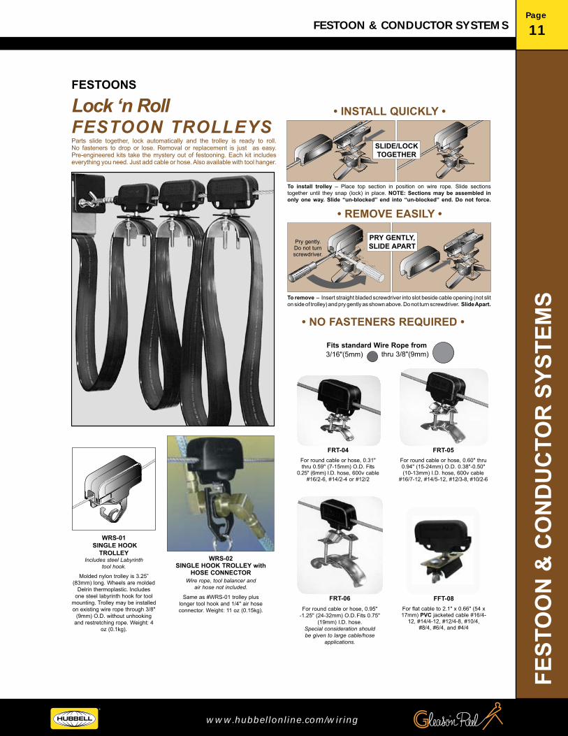
Molded nylon trolley is 3.25” (83mm) long. Wheels are molded
Delrin thermoplastic. Includes one steel labyrinth hook for tool
mounting. Trolley may be installed on existing wire rope through 3/8"
(9mm) O.D. without unhooking and restretching rope. Weight: 4
oz (0.1kg).
Same as #WRS-01 trolley plus longer tool hook and 1/4" air hose connector. Weight: 11 oz (0.15kg).
WRS-01 SINGLE HOOK
TROLLEYIncludes steel Labyrinth
tool hook.WRS-02
SINGLE HOOK TROLLEY with HOSE CONNECTOR
Wire rope, tool balancer and air hose not included.
Lock ‘n Roll FESTOON TROLLEYSParts slide together, lock automatically and the trolley is ready to roll. No fasteners to drop or lose. Removal or replacement is just as easy.Pre-engineered kits take the mystery out of festooning. Each kit includes everything you need. Just add cable or hose. Also available with tool hanger.
FFT-08 For flat cable to 2.1" x 0.66" (54 x 17mm) PVC jacketed cable #16/4-
12, #14/4-12, #12/4-8, #10/4, #8/4, #6/4, and #4/4
FRT-06For round cable or hose, 0.95"
-1.25" (24-32mm) O.D. Fits 0.75" (19mm) I.D. hose.
Special consideration should be given to large cable/hose
applications.
FRT-05For round cable or hose, 0.60" thru 0.94" (15-24mm) O.D. 0.38"-0.50" (10-13mm) I.D. hose, 600v cable
#16/7-12, #14/5-12, #12/3-8, #10/2-6
FRT-04For round cable or hose, 0.31" thru 0.59" (7-15mm) O.D. Fits
0.25" (6mm) I.D. hose, 600v cable #16/2-6, #14/2-4 or #12/2
• INSTALL QUICKLY •
• REMOVE EASILY •
3/16"(5mm) thru 3/8"(9mm)Fits standard Wire Rope from
• NO FASTENERS REQUIRED •
To install trolley – Place top section in position on wire rope. Slide sections together until they snap (lock) in place. NOTE: Sections may be assembled in only one way. Slide “un-blocked” end into “un-blocked” end. Do not force.
SLIDE/LOCK TOGETHER
To remove – Insert straight bladed screwdriver into slot beside cable opening (not slit on side of trolley) and pry gently as shown above. Do not turn screwdriver. Slide Apart.
PRY GENTLY, SLIDE APART
Pry gently. Do not turn screwdriver.
FESTOONS

FESTOO
N &
CO
ND
UC
TOR
SYSTEMS
Page
12 FESTOON & CONDUCTOR SYSTEMS
®
HUBBELL CANADA LP www.hubbellonline.com/wiring
OD
* Saddle sizes: Models shown on chart above are for 0.3"–0/59" dia. cable only. For larger diameters, use “05” or “06” at end of number, as shown here. FR04 = 0.30" to 0.59" (7–15mm) OD cable/hose. FR05 = 0.60" to 0.94" (15–24mm) OD cable/hose. FR06 = 0.95" to 1.25" (24–32mm) OD cable/hose.
(1) MINIMUM CABLE REQUIRED length listed in chart is enough for ACTIVE TRAVEL only, measured centerline to centerline; see diagrams below. ADD cable or hose to each end as required for hook-up to your system.(2) ACTIVE TRAVEL, SYSTEM LENGTH and MINIMUM CABLE values on charts are for 30" or 48" loop depths and are provided as planning guide only. Kits include necessary components for festoon system with 48" loop depth at system length shown. Loop depth may be varied to suit application.
FLAT CABLE KITS ROUND CABLE & HOSE KITS
2
3
1
Storage Distance (SD)
CL CL CL
System Length (SL)
7
4
2 3
5
2 71
6
Active Travel (AT)
FIXED CABLE
(FC)
MOVING CABLE (MC)
Loop Depth (LD)ORDER FLAT CABLE
SEPARATELY
8CL CL CL
System Length (SL)
Storage Distance (SD)7
4
2 3
5
8
2 716
Active Travel (AT)
FIXED CABLE
(FC)
MOVING CABLE (MC)
Loop Depth (LD)
ORDER ROUND CABLE OR HOSE SEPARATELY
KIT NUMBER EXPLANATION
Example: FR 04* – 03 Type Saddle size Number Trolleys (Round cable/hose) (0.30" –0.59" dia.) – (Three)
KIT NUMBER EXPLANATION
Example: FF 08 – 03 Type Saddle size Number Trolleys (Flat cable) (0.65"h x 2.0"w) – (Three)
Definitions AT = Active Travel: Distance moving end must travel to do job. SL = System Length: Anchor-point to anchor-point of wire rope. SD = Storage Distance: Wire rope hardware and trolleys butted together. LD = Loop Depth: Maximum height of loop formed by cable or hose.
Kit ComponentsWire Rope, length to suit SLHardware as requiredIntermediate trolleys, by modelEnd Clamp (1)
6
7
5 Tow Clamp/Clip (1)Bumper Stop (2)Tension Bracket, optional.Tow arm bracket, optional.
Kit Selection Procedure: You must know: 1– CABLE or HOSE: Use appropriate model chart for type (round or flat) cable/hose. If round, choose correct saddle size (FR04, FR05 or FR06)*.
2– LOOP DEPTH (LD): 30" loop and 48" loop shown for planning purposes. Final loop depth should be between these two examples. With a given number of trolleys, longer loop depth = longer travel. However, loop depth is often dictated by available clearance beneath wire rope.
3– ACTIVE TRAVEL (AT): Select kit which best fulfills requirements. If your system length must be longer than system length specified for active travel length you require, order by system length so wire rope supplied with kit will not be too short.
NOTE: Cable or hose are NOT INCLUDED. Order, separately, footage shown on model chart plus length needed at each end for hook-up.
Kits feature trolleys and include all necessary wire rope and hardware for complete festoon system. Cable or hose not included and must be ordered separately to suit application. Wire rope supplied for 48" loop depth plus extra for fastening at both ends.
ACTIVETRAVEL
“AT”
KITNO.
(PRICE)
SYSTEMLENGTH
“SL”
STORAGEDISTANCE
“SD”
(1)MINIMUM CABLE
REQUIRED
LOOP DEPTHFor planning purposes.(2)
30" 48"
Maximum cable size:0.65" x 2.0"(17 x 51mm)
LOOP DEPTHFor planning purposes.(2)
30" 48"
MINIMUM. May be greater with stiff cable or short loop.
LOOP DEPTHFor planning purposes.(2)
30" 48"12' 20' FF08–02 14' 23' 21" 15' 24'16' 27' FF08–03 19' 30' 25" 20' 32'20' 33' FF08–04 23' 37' 28" 24' 39'24' 40' FF08–05 27' 44' 32" 29' 47'28' 47' FF08–06 32' 51' 35" 34' 55'32' 54' FF08–07 36' 58' 39" 39' 63'36' 60' FF08–08 40' 65' 42" 42' 70'
ACTIVETRAVEL
“AT”
KITNO.
(PRICE)
SYSTEMLENGTH
“SL”
STORAGEDISTANCE
“SD”
(1)MINIMUM CABLE
REQUIRED
LOOP DEPTHFor planning purposes.(2)
30" 48"
Maximum cable size:0.65" x 2.0"(17 x 51mm)
LOOP DEPTHFor planning purposes.(2)
30" 48"
MINIMUM. May be greater with stiff cable or short loop.
LOOP DEPTHFor planning purposes.(2)
30" 48"10' 18' FR04*–02 13' 21' 21" 16' 25'14' 24' FR04*–03 17' 27' 25" 22' 34'17' 30' FR04*–04 21' 34' 28" 24' 42'21' 37' FR04*–05 25' 40' 32" 27' 50'25' 43' FR04*–06 28' 47' 35" 32' 58'28' 49' FR04*–07 32' 53' 39" 43' 67'32' 55' FR04*–08 36' 60' 42" 48' 75'
NYLON TROLLEYFESTOON KITS - WIRE ROPE
4 8
FESTOONS

FEST
OO
N &
CO
ND
UC
TOR
SYS
TEM
S
Page
13FESTOON & CONDUCTOR SYSTEMS
www.hubbellonline.com/wiring
A HUBBELL COMPANY
®
®
FESTOONSSTEEL TROLLEYFESTOON KITS - WIRE ROPE
CL CL CL
CL CL CL
The quickest way to select a Tag Line festoon system is to use kits. For single cables or hoses, select the number of trolleys (middle two digits) for your travel - all the necessary parts come in the box. Add exact cable/hose for your job and it’s finished.
SELECTING A KIT:STEP 1 Determine Active Travel (AT) required and choose the appropriate kit from either the Flat Cable (WF) or Round Cable/hose (WR) table.
STEP 2 Loop depth is assumed at 36" for all kits. Adjust to suit. Longer loop depth provides greater Active Travel, shorter loop depth provides less Active Travel. NOTE: Wire rope in kits is sufficient for System Length (SL) shown plus amount needed for securing at each end. If longer loop depth is to be used, order longer kit.
STEP 3 Cable/hose NOT INCLUDED. Order separately length shown on table plus amount needed at each end for hook up to your system.
4
2
3
1
Definitions AT = Active Travel: Distance moving end must travel to do job. SL = System Length: Anchor-point to anchor-point of wire rope. SD = Storage Distance: Wire rope hardware and trolleys butted together. LD = Loop Depth: Maximum height of loop formed by cable or hose.
Kit ComponentsWire Rope, length to suit SLHardware as requiredIntermediate trolleys, by modelEnd Clamp (1)
6
7
8
5 Tow Clamp/Clip (1)Bumper Stop (2)Tension Bracket, optional.Tow arm bracket, optional.
System Length (SL)
Storage Distance (SD)
7
4
23
5
271
6
Active Travel (AT)
System Length (SL)
Storage Distance (SD) Active Travel (AT)
FIXED CABLE
(FC)
MOVING CABLE (MC)
Loop Depth (LD)ORDER FLAT CABLE
SEPARATELY
8
KIT NUMBER EXPLANATION Example: WF 03 – 36 Type Number Trolleys Loop Depth (Flat cable) (Three) – (36")
7
4
23
5
271
6
FIXED CABLE
(FC)
MOVING CABLE (MC)
Loop Depth (LD)
ORDER ROUND CABLE OR HOSE SEPARATELY
8
KIT NUMBER EXPLANATION
Example: WR 03 – 36 Type Number Trolleys Loop Depth (Round cable) (Three) – (36")
FLAT CABLE KITS
ROUND** CABLE & HOSE KITS
* Minimum length of cable/ hose listed in charts above is enough for travel only. Add length needed at each end for hook-up to your system.** WR trolleys have saddles to handle cable or hose up to 0.94" O.D. (3/8" I.D. hose).
* Minimum length of cable/ hose listed in charts above is enough for travel only. Add length needed at each end for hook-up to your system.
KIT NUMBER
ACTIVETRAVEL
"AT"
CABLE/HOSEMIN.*
STORAGE LENGTH “SD”
SYSTEMLENGTH
“SL”
WF-03-36 20' 24' 25" 23' 0"WF-04-36 24' 29' 28" 27' 3"WF-05-36 29' 35' 32" 32' 9"WF-06-36 34' 41' 35" 38' 0"WF-07-36 39' 47' 39" 43' 4"WF-08-36 44' 52' 42" 48' 7"WF-09-36 49' 58' 45" 53' 10"WF-10-36 54' 60' 51" 59' 4"
KIT NUMBER
ACTIVETRAVEL
"AT"
CABLE/HOSEMIN.*
STORAGE LENGTH “SD”
SYSTEMLENGTH
“SL”
WR-03-36 17' 26' 25" 20' 0"WR-04-36 22' 32' 28" 25' 5"WR-05-36 26' 38' 32" 29' 9"WR-06-36 31' 45' 35" 35' 0"WR-07-36 35' 51' 39" 39' 4"WR-08-36 39' 60' 42" 43' 7"

FESTOO
N &
CO
ND
UC
TOR
SYSTEMS
Page
14 FESTOON & CONDUCTOR SYSTEMS
®
HUBBELL CANADA LP www.hubbellonline.com/wiring
FESTOONS
FLAT CABLE FESTOON COMPONENTS
ROUND CABLE & HOSE FESTOON COMPONENTS
3.25 (83)
4.9(124)
0.8(21)
1.6(41)
3(76)
1(25)
2.1(54)
0.6(16)
2 (51)dia.
0.66(17)max.
0.66(17)max.
0.8(21)
Dia. Range
“A”
3.5 (89)
3.25 (83)
B
D
1.6(41)
0.6(16)
0.562(14)dia.
0.562(14)dia.
Dia. Range
“A”
TOW ARM
3.5 (89)
3.25 (83)
B
D
0.9(24)
0.9 (24)
3.25 (83)
2.1(54)
0.66(17)max.
2.3(59)
2.1(54) 2 (51)
dia.
TOW ARM3.3 (84)
1.7 (43)
1.5(38)
1(25)
2 (51) dia.
1 (25) dia.
3.5(90)
1.25(32)
3.7 (94)3.25 (83)2.1 (54)
3.3 (84)
Dia. Range
“A”
B
D
1.5(38)
1 (25) dia.
1.25 (32)
3.3(84)
0.94(24)
1.1(28)
Dia. Range
“A”
B
D
0.75 (51) dia.
3.3 (84)
4.25(108)
1(25)
2 (51)dia.
0.75(19)dia.
2.4(61)0.94
(24)
1.1 (28)
3.7 (94)
3.25 (83)2.1 (54) 0.66
(17)max.
Lock ‘n Roll TROLLEYFFT-08
Description: Fiberglass reinforced molded nylon with
zinc plated steel cable clamp.
STEEL TROLLEYW25–FC–32
Description: Zinc plated steel with dual nylon wheels.
Zinc plated steel cable clamp.
TOW CLAMPW25–FT–02
Description: Steel with zinc plating.
END CLAMPW25–FE–02
Description: Steel with zinc plating.
Lock ‘n Roll TROLLEYSTEEL TROLLEY TOW CLAMP END CLAMP
ADD TO FESTOON KITS OR BUILD FROM SCRATCH STEEL OR Lock ‘n Roll TROLLEYS
COMPONENTS - Wire Rope Festoon
OPTIONAL Components Flat Cable, Round Cable, Hose, Connectors: see “CABLE & HOSE DATA”.
Tension Bracket W25–BR–01Anchor ends of wire rope and fixed end of festoon.
Tow Arm W25–TA–01Use on moving end of festoon with Tow Clamp (above).
18 (457)
1.2 (30)
3 (76)
4 (102)0.75 (19)
1.5 (38)
0.406 (10) dia.(4) HOLES
18 (457)
8 (203)
5 (127) 1.5
(38)
6 (152)0.406(10) DIA.
(4) HOLES 0.562(14) DIA.(4) HOLES
2.5 (64)
3 (76)
2 (51)
3 (76)
3 (76)
3 (76)
Description: Steel with zinc plating. Description: Zinc plated steel with dual nylon wheels.
Zinc plated steel cable clamp.
Description: Fiberglass reinforced molded nylon with
zinc plated steel cable clamp.
Description: Steel with zinc plating.
* For type of hose or cable included in each O.D. range, refer to previous pages or “CABLE & HOSE DATA”.
MODEL NUMBER
*CABLE O.D. “A”in. (mm)
“B”in.
(mm)
“D”in.
(mm)
W25-RT-11 0.31–0.59(7–15)
1.25(32)
2.75(70)
W25-RT-12 0.60–0.94(15–24)
1.44(37)
3.86(98)
W25-RT-13 0.95–1.25(24–32)
1.7(4.3
5.0(127)
MODEL NUMBER
*CABLE O.D. “A”in. (mm)
“B”in.
(mm)
“D”in.
(mm)
W25-RC-11 0.31–0.59(7–15)
2.75(70)
2.75(70)
W25-RC-12 0.60–0.94(15–24)
2.94(75)
3.86(98)
W25-RC-13 0.95–1.25(24–32)
3.2(81)
5.0(127)
MODEL NUMBER
*CABLE O.D. “A”in. (mm)
“B”in.
(mm)
“D”in.
(mm)
FRT-04 0.31–0.59(7–15)
2.4(61)
2.75(70)
FRT-05 0.60–0.94(15–24)
2.6(66)
3.86(98)
FRT-06 0.95–1.25(24–32)
2.9(74)
5.0(127)
MODEL NUMBER
*CABLE O.D. “A”in. (mm)
“B”in.
(mm)
“D”in.
(mm)
W25-RE-11 0.31–0.59(7–15)
4.06(103)
2.75(70)
W25-RE-12 0.60–0.94(15–24)
4.25(108
3.86(98)
W25-RE-13 0.95–1.25(24–32)
4.5(114
5.0(127)
Hardware Kit W25–HW–01Includes: (2) 1" ID x 6" lg x .500" body eye bolts w/ hex nuts, (2) galv. steel thimbles, (4) galv. steel clips, (1) bumper stop (neoprene rubber); wt. 2.5 lbs.
Wire Rope W25–WR–01.25" OD Nylon-coated Wire Rope; wt. .086 lbs/ft.

FEST
OO
N &
CO
ND
UC
TOR
SYS
TEM
S
Page
15FESTOON & CONDUCTOR SYSTEMS
www.hubbellonline.com/wiring
A HUBBELL COMPANY
®
®
SPECIALLY DESIGNED FOR OVERHEAD CRANESSTEEL TRACK FESTOON SYSTEM KITS
FESTOONS
TRACK BRACKET –THREE PIECESSupports track to cross arms.
CROSS ARMSSupport festoon track.
NOTE: Models with cross arms only.
CROSS ARM
TRACK SPLICEEnds of both track sections
must be visible through “peep” hole to assure secure splice.
BEAM CLAMPSFasten cross arms to I-beam. Includes track nuts. TOW TROLLEY
(Cross Conductor Kit Only)Last trolley on moving end of system.
INTERMEDIATE TROLLEYS
FIXED CABLE CLAMP
Secures cable and acts as stop on
“non-moving “ end.
JUNCTION BOX TROLLEY
(Push Button Kits only)Has twin trolleys.Used with push button control station at moving end of festoon system.
JUNCTION BOX
PENDANT PUSH BUTTON
CONTROL STATION(not included)
PENDANTCABLE
(not included)
ANCHOR BRACKET–WELDMENTUse one at each end of track.
CROSS ARM
SET SCREW
Install a high speed, smooth operating festoon system on an overhead crane or similar application. Kits include all required parts; track and trolleys, mounting clamps, cross support arms, even electrical cable which has been pre-installed on the trolleys. To install, clamp cross arms to beam or other support, affix track to support beams, roll trolleys into track and make electrical connections on each end. It’s that simple. It’s that fool-proof. Kits also available without cross arms and with spark resistant trolleys. Refer to model charts on following pages for system lengths and cables available.

FESTOO
N &
CO
ND
UC
TOR
SYSTEMS
Page
16 FESTOON & CONDUCTOR SYSTEMS
®
HUBBELL CANADA LP www.hubbellonline.com/wiring
14 Gauge Track Festooned Push Button (less pendant)16 Conductor Flat Cables (#16-8C & #16-8C)
CRANE SPANW/cross arms
W/O cross arms*
20'HNA14241HNA14242
10'HNA13141HNA13142
30'HNA14341HNA14342
40'HNA14441HNA14442
50'HNA14541HNA14542
60'HNA14641HNA14642
70'HNA14741HNA14742
80'HNA14841HNA14842
90'HNA14941HNA14942
100'HNA15041HNA15042
SYSTEM INCLUDES:Roller Track (10 foot sections)Track SpliceTrack Bracket*Anchor Bracket*Cross Arms (30")*Locking Beam ClampEnd StopFixed Cable ClampControl TrolleyIntermediate TrolleyControl Cable #16-8c (length = system + hook-up)Flat Cable ConnectorJunction Box Assembly
2122481113221
1002241112221
32426121115221
43628161116221
548210201118221
65102122411110221
76122142811112221
87142163211114221
98162183611116221
109182204011118221
14 Gauge Track Cross Conductors12 Conductor Flat Cables (#12-4C & #16-8C)
SYSTEM INCLUDES:
CRANE SPANW/cross arms
W/O cross arms*
Roller Track (10 foot sections)Track SpliceTrack Bracket*Anchor Bracket*Cross Arms (30")*Locking Beam ClampEnd StopFixed Cable ClampTow TrolleyIntermediate TrolleyPower Cable #12-4C (length = system + hook-up)Control Cable #16-8c (length = system + hook-up)Flat Cable Connector
20'HNA18241HNA18242
2122481113114
10'HNA18141HNA18142
1002241112114
32426121115114
43628161116114
548210201118114
65102122411110114
30'HNA18341HNA18342
40'HNA18441HNA18442
50'HNA18541HNA18542
60'HNA18641HNA18642
70'HNA18741HNA18742
80'HNA18841HNA18842
90'HNA18941HNA18942
100'HNA19041HNA19042
76122142811112114
87142163211114114
98162183611116114
109182204011118114
14 Gauge Track Cross Conductors12 Conductor Flat Cables (#14-4C & #16-8C)
Roller Track (10 foot sections)Track SpliceTrack Bracket*Anchor Bracket*Cross Arms (30")*Locking Beam ClampEnd StopFixed Cable ClampTow TrolleyIntermediate TrolleyPower Cable #14-4C (length = system + hook-up)Control Cable #16-8c (length = system + hook-up)Flat Cable Connector
2122481113112
1002241112112
32426121115112
43628161116112
548210201118112
65102122411110112
76122142811112112
SYSTEM INCLUDES:
CRANE SPANW/cross arms
W/O cross arms*
20'HNA15241HNA15242
10'HNA15141HNA15142
87142163211114112
98162183611116112
109182204011118112
30'HNA15341HNA15342
40'HNA15441HNA15442
50'HNA15541HNA15542
60'HNA15641HNA15642
70'HNA15741HNA15742
80'HNA15841HNA15842
90'HNA15941HNA15942
100'HNA13441HNA13442
* Cross arms, track brackets and anchor brackets not included.
FESTOONS

FEST
OO
N &
CO
ND
UC
TOR
SYS
TEM
S
Page
17FESTOON & CONDUCTOR SYSTEMS
www.hubbellonline.com/wiring
A HUBBELL COMPANY
®
®
14 Gauge Track Cross Conductors12 Conductor Flat Cables (#10-4C & #16-8C)
14 Gauge Track Cross Conductors12 Conductor Flat Cables (#8-4C & #16-8C)
14 Gauge Track Cross Conductors4 Conductor Flat Cables (#14-4C)
SYSTEM INCLUDES:
CRANE SPANW/cross arms
W/O cross arms*
Roller Track (10 foot sections)Track SpliceTrack Bracket*Anchor Bracket*Cross Arms (30")*Locking Beam ClampEnd StopFixed Cable ClampTow TrolleyIntermediate TrolleyPower Cable #8-4C (length = system + hook-up)Control Cable #16-8c (length = system + hook-up)Flat Cable Connector
20'HNA19241HNA19242
2122481113114
10'HNA19141HNA19142
1002241112114
32426
121115114
43628
161116114
5482
10201118114
65
102
1224111
10114
30'HNA19341HNA19342
40'HNA19441HNA19442
50'HNA19541HNA19542
60'HNA19641HNA19642
Roller Track (10 foot sections)Track SpliceTrack Bracket*Anchor Bracket*Cross Arms (30")*Locking Beam ClampEnd StopFixed Cable ClampTow TrolleyIntermediate TrolleyPower Cable #10-4C (length = system + hook-up)Control Cable #16-8c (length = system + hook-up)Flat Cable Connector
2122481113114
1002241112114
32426
121115114
43628
161116114
5482
10201118114
65
102
1224111
10114
70'HNA19741HNA19742
80'HNA19841HNA19842
90'HNA19941HNA19942
100'HNA20041HNA20042
SYSTEM INCLUDES:
CRANE SPANW/cross arms
W/O cross arms*
Roller Track (10 foot sections)Track SpliceTrack Bracket*Anchor Bracket*Cross Arms (30")*Locking Beam ClampEnd StopFixed Cable ClampTow TrolleyIntermediate TrolleyPower Cable #14-4C (length = system + hook-up)Flat Cable Connector
20'HNA15243HNA15244
212248111312
10'HNA15143HNA15144
100224111212
32426
12111512
43628
16111612
5482
1020111812
65
102
1224111
1012
30'HNA15343HNA15344
40'HNA15443HNA15444
50'HNA15543HNA15544
60'HNA15643HNA15644
76
122
1428111
1212
70'HNA15743HNA15744
80'HNA15843HNA15844
90'HNA15943HNA15944
100'HNA13443HNA13444
SYSTEM INCLUDES:
CRANE SPANW/cross arms
W/O cross arms*
20'HNA20241HNA20242
10'HNA20141HNA20142
30'HNA20341HNA20342
40'HNA20441HNA20442
50'HNA20541HNA20542
60'HNA20641HNA20642
70'HNA20741HNA20742
80'HNA20841HNA20842
90'HNA20941HNA20942
100'HNA21041HNA21042
* Cross arms, track brackets and anchor brackets not included.
76
122
1428111
12114
87
142
1632111
14114
98
162
1836111
16114
109182204011118114
87
142
1632111
1412
98
162
1836111
1612
10918220401111812
76
122
1428111
12114
87
142
1632111
14114
98
162
1836111
16114
109182204011118114
FESTOONS

FESTOO
N &
CO
ND
UC
TOR
SYSTEMS
Page
18 FESTOON & CONDUCTOR SYSTEMS
®
HUBBELL CANADA LP www.hubbellonline.com/wiring
SYSTEM INCLUDES:
14 Gauge Track Cross Conductors4 Conductor Flat Cables (#8-4C)
SYSTEM INCLUDES:
SYSTEM INCLUDES:
14 Gauge Track Cross Conductors4 Conductor Flat Cables (#12-4C)
14 Gauge Track Cross Conductors4 Conductor Flat Cables (#10-4C)
CRANE SPANW/cross arms
W/O cross arms*
Roller Track (10 foot sections)Track SpliceTrack Bracket*Anchor Bracket*Cross Arms (30")*Locking Beam ClampEnd StopFixed Cable ClampTow TrolleyIntermediate TrolleyPower Cable #10-4C (length = system + hook-up)Flat Cable Connector
20'HNA18243HNA18244
212248111312
10'HNA18143HNA18144
100224111212
32426
12111512
43628
16111612
5482
1020111812
65
102
1224111
1012
30'HNA18343HNA18344
40'HNA18443HNA18444
50'HNA18543HNA18544
60'HNA18643HNA18644
76
122
1428111
1212
Roller Track (10 foot sections)Track SpliceTrack Bracket*Anchor Bracket*Cross Arms (30")*Locking Beam ClampEnd StopFixed Cable ClampTow TrolleyIntermediate TrolleyPower Cable #12-4C (length = system + hook-up)Flat Cable Connector
212248111312
100224111212
32426
12111512
43628
16111612
5482
1020111812
65
102
1224111
1012
70'HNA18743HNA18744
80'HNA18843HNA18844
90'HNA18943HNA18944
100'HNA19043HNA19044
CRANE SPANW/cross arms
W/O cross arms*
Roller Track (10 foot sections)Track SpliceTrack Bracket*Anchor Bracket*Cross Arms (30")*Locking Beam ClampEnd StopFixed Cable ClampTow TrolleyIntermediate TrolleyPower Cable #8-4C (length = system + hook-up)Flat Cable Connector
20'HNA20243HNA20244
212248111312
10'HNA20143HNA20144
100224111212
32426
12111512
43628
16111612
5482
1020111812
65
102
1224111
1012
30'HNA20343HNA20344
40'HNA20443HNA20444
50'HNA20543HNA20544
60'HNA20643HNA20644
70'HNA20743HNA20744
80'HNA20843HNA20844
90'HNA20943HNA20944
100'HNA21043HNA21044
CRANE SPANW/cross arms
W/O cross arms*
20'HNA19243HNA19244
10'HNA19143HNA19144
30'HNA19343HNA19344
40'HNA19443HNA19444
50'HNA19543HNA19544
60'HNA19643HNA19644
70'HNA19743HNA19744
80'HNA19843HNA19844
90'HNA19943HNA19944
100'HNA20043HNA20044
* Cross arms, track brackets and anchor brackets not included.
76
122
1428111
1212
87
142
1632111
1412
98
162
1836111
1612
10918220401111812
87
142
1632111
1412
98
162
1836111
1612
10918220401111812
76
122
1428111
1212
87
142
1632111
1412
98
162
1836111
1612
10918220401111812
FESTOONS

FEST
OO
N &
CO
ND
UC
TOR
SYS
TEM
S
Page
19FESTOON & CONDUCTOR SYSTEMS
www.hubbellonline.com/wiring
A HUBBELL COMPANY
®
®
OPTIONAL Components Flat and Round Kits
FESTOONS
ROUND CABLE TROLLEY 1 = C35-RC-11 & 2 = C35-RC-12
ROUND CABLE TOW TROLLEY1 = C35-RT-11 & 2 = C35-RT-12
ROUND CABLE END CLIP1 = C35-RE-11 & 2 = C35-RE-12
Series “CR” for ROUND Cable or Hose
FLAT CABLE TROLLEY C35-FC-32Trolley Weight = 0.84 lbs
FLAT CABLE TOW TROLLEY C35-FT-52Trolley Weight = 2.28 lbs
FLAT CABLE END CLAMP C35-FE-02Trolley Weight = 1.46 lbs
C-RAIL TRACK SECTIONS — GALVANIZEDC35-TR-06 Weight = 6.3 lbs
END STOPWS30-ES
Weight = 0.3 lbs
ADD TO C–RAIL FESTOON KITS SHOWN ON PRECEDING PAGESCOMPONENTS - C-Rail Festoon
TOW ARMAttaches to your machine and inserts into Tow Trolley to tow the system.
Series “CF” for FLAT Cable
Accessories for Flat and Round Kits* Standard Round Kits include Trolleys & Clips with O.D. Code “2” (fits std. 3/8 in. I.D. hose).
MULTIPLE CABLE CONNECTOR
FLAT-TO-ROUND CABLECONNECTOR SET
*Please provide cutting pattern for #MCC-1C.
1.0 dia.(25) 5.5
(140)
2.1(54)
2.0(51)
1.0(25)
1.0(25)
1.0 dia.(25)
1.0dia.(25)
0.6 max(14)
3.25(83)
2.1(54)
3.3(84)
3.1(79)
3.1(79)
2.0(51) 2.0
(51)
1.75(44)
2.8(70)
1.75(44)
2.0(51)2.25
(57)72.0(1829)
1.3(32)
1.2(30)
2.5(64)
2.5(64)
0.75(19)
1.6(40)
1.6(40)
0.2(5)
16.0(406)
1.0(25)
0.08 THK(2)
0.5(12)
1.4(36)
1.6(41)
4.0(102)
2.6(70)
5.0(127)1.0
(25)
1.0 dia.(25)
5.0(127)
1.0(25)1.0 dia.
(25)
1.5 max(38) 2.1
(54)
3.25(83)
3.75(95)
8.2(208)
1.0(25)
1.1(27)
1.5 max(38)
3.25(83)
0.9(23)
1.1(17)
BB
B
Dia. Range A
Dia. Range A Dia.
Range A
5.5(140)
1.80(46)
1.8(46)
3.6(92)
1.6(40)
DD
D
1.6(40)
1.4(36)
1.6(41)
4.0(102)
NOTCHED COUPLER
C35-CPN-01Weight = 1.0 lbs
COUPLER/HANGER BRACKETC35-CP-02
Weight = 1.25 lbs
O.D.CODE*
*CABLE O.D. “A”in. (mm)
“B”in.
(mm)
“D”in.
(mm)
WGTlb.
(kg)
1 0.31–0.59(8–15)
6.5(165)
2.75(70)
2.3(1.05
2 0.95–1.25(24–32)
6.7(170)
3.9(98)
2.5(1.10)
O.D.CODE*
*CABLE O.D. “A”in. (mm)
“B”in.
(mm)
“D”in.
(mm)
WGTlb.
(kg)
1 0.31–0.59(8–15)
1.25(32)
2.75(70)
1.4(.63)
2 0.95–1.25(24–32)
1.4(37)
3.9(98)
1.5(.69)
O.D.CODE*
*CABLE O.D. “A”in. (mm)
“B”in.
(mm)
“D”in.
(mm)
WGTlb.
(kg)
1 0.31–0.59(8–15)
1.10(32)
2.75(70)
0.9(.40)
2 0.95–1.25(24–32)
1.25(27)
3.9(98)
1.0(.46)
DESCRIPTION MODELNUMBER
Blank Connector MCC-1UPre-cut Connector MCC-1C
DESCRIPTION WGTlb. (kg)
MODEL NUMBER
TOW ARM 1.3 (59) CTA-01
Go quickly and safely from flat to round cable. Consists of one each male and female plugs designed to accept flat or round cable and lock together securely. Plugs are 3-pole, 4-wire plus ground and will accommodate round cable sizes #14 AWG through #10 AWG; flat cable up to 1.00" wide. Ratings: 20 amp, 480 volt, 3 phase. NEMA configuration #L16-20. Plugs are double-insulated plastic and resist impact, corrosion and most chemicals.
DESCRIPTION MODEL NUMBER
Set of 2 Locking Plugs LC-01
7.2(183)
2.25(57)
2.9(73)
2.3(59)
1.5(38)
6.6(167)
Aluminum cast connector provides a weathertight connection between multiple cables (flat and/or round) and junction box. Order un-cut (blank) model and machine fiber-board stiffener and rubber insert to suit, OR order a pre-cut connector by providing cutting pattern.

FESTOO
N &
CO
ND
UC
TOR
SYSTEMS
Page
20 FESTOON & CONDUCTOR SYSTEMS
®
HUBBELL CANADA LP www.hubbellonline.com/wiring
T-TRACK FESTOON SYSTEMS
T-TRACK Heavy Duty Festoon Cable Systems are specially designed for applications where a more robust system is required to support heavier loads at wider support spacings. Made of a high strength aluminum extrusion, these systems are rugged enough to handle the most demanding applications.
The track is supplied in convenient lengths which simply bolt together with a heavy duty joint assembly, and it can be curved to a minimum of 48” (1.2M) at various angles if required. The trolleys roll along the outside of the track, which allows for easy inspection and changing of the rollers. These trolleys utilize the same rugged, fi eld proven rollers that are used on the C-TRACK trolleys, and they are supplied with anti-lift rollers as a standard feature. All standard trolleys feature durable steel wheels.
T-Track Profi le
SECTION LENGTH NET WGT. CAT. NO.
10 ft. .87 lbs./ft. F-HT10
20 ft. .87 lbs./ft. F-HT20
T-Track sections are made of a heavy duty aluminum extrusion, of 1/8” cross section. T-Track may be cut to customer specifi ed lengths. T-Track may also be curved. Consult Factory for details.
T-Track Bolted Joint Assembly
NET WGT. CAT. NO.
1.5 lbs. F-HTJ1
Coupling set consists of two parts. The top portion is used to bolt sections of T-Track together. Bolts are inserted through the prepunched holes in the track sections and through the coupling plate, then securely fastened on the top. The lower portion is installed through the curved section, and then tightened with set screws.
T-Track Control Box Assembly
TYPE NET WGT. CAT. NO.
Flat 3” dia. 5.20 lbs. F-HCB
Round Med. 0.60”-0.94” 5.50 lbs. R-HCB
Round Lrg. 0.95”-1.25” 5.55 lbs. R-HCBL
Used to support the control box / pushbutton pendant station. Equipped with steel wheels, hardware, and cable saddle.

FEST
OO
N &
CO
ND
UC
TOR
SYS
TEM
S
Page
21FESTOON & CONDUCTOR SYSTEMS
www.hubbellonline.com/wiring
A HUBBELL COMPANY
®
®
T-Track End Stop Assembly
NET WGT. CAT. NO.
0.6 lbs. F-HTS
Used to stop the trolleys at the active travel end of the track. One required for each run of T-Track. End View
T-Track Tow Arm
TYPE NET WGT. CAT. NO.
Flat 3” dia. 3.25 lbs. F-HTA
Round Med. 0.60”-0.94” 3.50 lbs. R-HTA
Round Lrg. 0.95”-1.25” 3.75 lbs. R-HTAL
Cable saddle attaches to heavy gauge steel track to mount on moving equipment which is to be electrifi ed.
T-Track Standard Trolley Assembly
TYPE NET WGT. CAT. NO.
Flat 3” dia. 3.25 lbs. F-HC5A
Round Med. 0.60”-0.94” 3.50 lbs. R-HC5A
Round Lrg. 0.95”-1.25” 3.75 lbs. R-HC5AL
Flat or round cable saddle. Cable may be stacked in saddle. Features anti-lift rollers and steel wheels as standard equipment.
T-Track End Clamp Assembly
TYPE NET WGT. CAT. NO.
Flat 3” dia. 0.9 lbs. F-HTE
Round Med. 0.60”-0.94” 3.5 lbs. R-HTE
Round Lrg. 0.95”-1.25” 3.75 lbs. R-HTEL
Flat or round cable saddles with hardware used to secure cable at storage end of track. One required for each run of T-Track.
End View
Round Cable Saddle shown
T-Track Hanger Assemblies
SUPPORT TYPE NET WGT. CAT. NO.
Angle Iron Support Brackets 0.8 lbs. F-HTH
C-Track Crossarm 0.8 lbs. F-HTEH/CT
Strut Track Support Bracket 0.8 lbs. F-HTH/ST
Flat or round cable saddles with hardware used to secure cable at storage end of track. One required for each run of T-Track.
T-Track Tow Trolleys
TYPE NET WGT. CAT. NO.
Flat 3” dia. 4.50 lbs. F-HCT
Round Med. 0.60”-0.94” 4.75 lbs. R-HCTA
Round Lrg. 0.95”-1.25” 5.00 lbs. R-HCTAL
Lead trolley with fl at or round cable saddle. Insert system’s tow arm to maneuver festoon cable system.

FESTOO
N &
CO
ND
UC
TOR
SYSTEMS
Page
22 FESTOON & CONDUCTOR SYSTEMS
®
HUBBELL CANADA LP www.hubbellonline.com/wiring
F-IT-S3/5.7 Intermediate or Tow Trolley with fl at cable saddleF-IT-S3/5.7D Intermediate or Tow
Trolley with dual fl at cable saddles
F-ITB-S3/5.7 Control Box Trolley for the push button pendant connection
F-IT-S3/5.7R2 - 0.60”-0.94” diaF-IT-S3/5.7R3 - 0.94”-1.25” dia Intermediate or Tow Trolley with
steel saddle for round cable/hose
BENEFITS OF CONSTRUCTION
Steel construction with zinc fi nish for moisture protection
Steel chassis expands for a range of S-beam sizes (S3 x 5.7, S4 x 7.7, S6 x 12.5 - consult factory for other beam sizes)
Wheels are manufactured with threaded axels, bolted (not riveted) onto the chassis for easy replacement if required
Our S-BEAM Trolleys are designed with your applications in mind. Economical, durable and expandable, our festoon cable trolley runs on various size S-beams (S3 x 5.7, S4 x 7.7, S6 x 12.5 - consult factory for other beam sizes). These trolleys roll on 4 steel ball bearing wheels that have a static load capacity of 1000 lbs. each. This provides a rolling capacity of 154 lbs at 262 ft per minute. Multiple cable saddle confi gurations provide a variety of cable carrying options for single or dual fl at cable or round cable.
F-IES End Stop
F-ICE/R2 - 0.60”-0.94” dia RoundF-ICE/R3 - 0.94”-1.25” dia RoundF-ICE - single saddle 3” dia FlatF-ICE-D - dual saddle 3” dia FlatEnd Clamps with choice of trolley

FEST
OO
N &
CO
ND
UC
TOR
SYS
TEM
S
Page
23FESTOON & CONDUCTOR SYSTEMS
www.hubbellonline.com/wiring
A HUBBELL COMPANY
®
®
“X” DIMENSION CATALOG NO.
12” Tow Arm F-CTA-F12
15” Tow Arm F-CTA-F15
18” Tow Arm F-CTA-F18
S-BEAM DRAWINGS / DIMENSIONS
S-Beam
Tow Arm
TOW ARMS
Front ViewSide View
Front View Side View
RSRHKStrain Relief Kit
4.0”5.5”
3.0” dia

FESTOO
N &
CO
ND
UC
TOR
SYSTEMS
Page
24
®
HUBBELL CANADA LP www.hubbellonline.com/wiring®
HUBBELL CANADA LP www.hubbellonline.com/wiring