fg cubic photoelectric sensor - acisensors.com and receiver with max detecting range of 50 m ... fg...
TRANSCRIPT

Photoelectric SensorsCatalogue Cod. CAT3EFG1261301Catalogue FG - english - Ed.01/2013
FGCubic Photoelectric Sensor

2/3
www.microdetectors.com
automatic doors and gates
wood industry
logistic and automatic warehouse
packaging industry
automotive industry
Cubic
FGSeries
Industries and applications
Products
FG cubic

IP67
Compact Rectangular photoelectric switch characterized by high performances and high detection
distances
Cable output or with revolving connector, NPN or PNP output (DC models) and SPDT voltage free
relay output (AC models)
Selectable LO/DO output status
Totally protected against electrical damages
Background suppressions models: 310mm, 600 mm
Reflex polarized sensitivity adjustment 12 m
Emitter and Receiver with max detecting range of 50 m
Sensitive adjustment models
Double Multifunction LED indicator: output state and using the pointing
Main Features
Certifications
Protection degree

4/5
FG Cubic Photoelectric Sensor range is composed by two different types of Background Sup-pression with detecting distances of 600 mm, polarized retroreflective (12m) and the barriers ver-sion (Emitter-Receiver 50m).Its small dimensions, M12 rotatable connector or pigtail with which the sensor is equipped, allow the installment of the product in very small spaces.The highly visible Led allows easy alignments, ensuring a bigger safety application in adverse environments.However, the product has a low sensitive in presence of dirt or dust on the optical lens.
FG Cubic Photoelectric Sensor
Pack Content
further commercial and technical documents available
High resolution pictures
Products
FG cubic
Installation manual (English + Italian): CAT8BFG1260501
ST82 knob regulation accessory for the models with sensitive adjustment
N° 1 mounting bracket + N° 2 screw with bolts and washers
N° 2 mounting bracket + N° 4 screw with bolts and washers, only for FGRHD/**-**
N° 1 RL 123 reflex, only for FGRN/**-**
Product packed in bags
-
customization already tested
minimum quantity that can be ordered
1 pcs

FG R W 0 0P A/ -
FG
R
W
S
N
H
D
HD
0
D
P
N
0
T
0
A
E
FGRS/0N-0AFGRW/0N-0A
FGRS/0P-0AFGRW/0P-0A
FGRS/0N-0EFGRW/0N-0E
FGRS/0P-0EFGRW/0P-0E
FGRS/DT-0AFGRW/DT-0A
FGRN/0N-0A FGRN/0P-0A FGRN/0N-0E FGRN/0P-0E FGRN/DT-0A
FGRHD/0N-0A FGRHD/0P-0A FGRHD/0N-0E FGRHD/0P-0E FGRHD/DT-0A
High resolution pictures
code description
Compact cubit photoelectric switch
Visible red emission LED
Adjut. dist. background suppression 600 mm
Adjust. dist background suppression 310 mm
Reflex polarized sensitivity adjustment 12 m
Emitter 50 m
Receiver with sensitivity adjustment 50 m
Emitter + Receiver with sensitivitiy adjustment
Supply voltage 10...30V cc/dc
Supply voltage 24...24V cc/dc / 24...240V ca/ac
PNP logic output
NPN logic output
Emitter
SPDT voltage free relay output
Plastic ousing
Cable exit
M12 plug cable exit
available models
model
310 mm600 mm
12 m
distance adjustment
yes
AC modelscable
Background suppression
polarized
emitter + receiver 50 m
M12 plug
3 class models: 3 class models can be subject to delays in delivery terms or limits for the quantities to be ordered.
NPN PNP NPN PNP
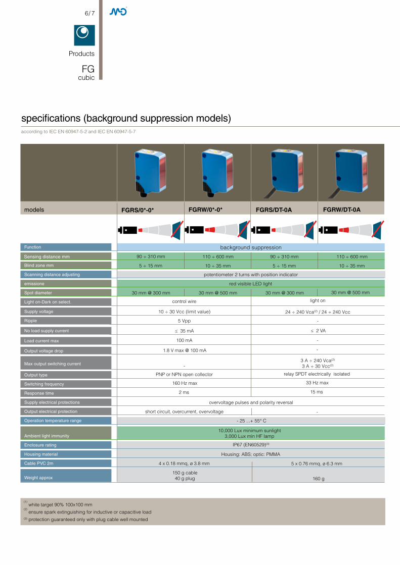
6/ 7
FGRS/0*-0* FGRW/0*-0* FGRS/DT-0A FGRW/DT-0A
Products
FG cubic
specifications (background suppression models)
Function
Blind zone mm
Scanning distance adjusting
emissione
Spot diameter
Light on-Dark on select.
Supply voltage
Ripple
No load supply current
Load current max
Output voltage drop
Max output switching current
Output type
Switching frequency
Response time
Supply electrical protections
Output electrical protection
Operation temperature range
Ambient light immunity
Enclosure rating
Housing material
Cable PVC 2m
Weight approx
Sensing distance mm
models
according to IEC EN 60947-5-2 and IEC EN 60947-5-7
(1) white target 90% 100x100 mm
(2) ensure spark extinguishing for inductive or capacitive load
(3) protection guaranteed only with plug cable well mounted
background suppression
potentiometer 2 turns with position indicator
red visible LED light
30 mm @ 300 mm
control wire
≤ 35 mA
overvoltage pulses and polarity reversal
short circuit, overcurrent, overvoltage
- 25 ...+ 55° C
10,000 Lux minimum sunlight3,000 Lux min HF lamp
IP67 (EN60529)(3)
Housing: ABS; optic: PMMA
90 ÷ 310 mm 110 ÷ 600 mm 90 ÷ 310 mm 110 ÷ 600 mm
5 ÷ 15 mm 10 ÷ 35 mm 5 ÷ 15 mm 10 ÷ 35 mm
light on
10 ÷ 30 Vcc (limit value) 24 ÷ 240 Vca(2) / 24 ÷ 240 Vcc
5 Vpp -
≤ 2 VA
100 mA -
1.8 V max @ 100 mA -
-3 A ÷ 240 Vca(2)
3 A ÷ 30 Vcc(2)
PNP or NPN open collector relay SPDT electrically isolated
160 Hz max 33 Hz max
2 ms 15 ms
-
4 x 0.18 mmq, ø 3.8 mm 5 x 0.76 mmq, ø 6.3 mm
150 g cable40 g plug 160 g
30 mm @ 500 mm 30 mm @ 300 mm 30 mm @ 500 mm

models FGRN/0*-0* FGRN/DT-0A
specifications (reflex polarized models)according to IEC EN 60947-5-2 and IEC EN 60947-5-7
(1) with RL 123 included reflector
(2) ensure spark extinguishing for inductive or capacitive load
(3) protection guaranteed only with plug cable well mounted
reflex polarized models
potentiometer 2 turns with position indicator
red visible LED light
approx. 260 mm @ 8 m
control wire
35 mA
overvoltage pulses and polarity reversal
short circuit, overcurrent, overvoltage
- 25 ...+ 55° C
10,000 Lux minimum sunlight3,000 Lux min HF lamp
IP67 (EN60529)(3)
Housing: ABS; optic: PMMA
12 m
0,01 m
light on
10 ÷ 30 Vcc (limit value) 24 ÷ 240 Vca(2) / 24 ÷ 240 Vcc
5 Vpp -
≤ 2 VA
100 mA -
1.8 V max @ 100 mA -
-3 A ÷ 240 Vca(2)
3 A ÷ 30 Vcc(2)
PNP or NPN open collector relay SPDT electrically isolated
1,000 Hz max 33 Hz max
0,15 ms 15 ms
-
4 x 0,18 mmq, ø 3,8 mm 5 x 0,76 mmq, ø 6,3 mm
150 g cable40 g plug 160 g
Function
Blind zone mm
Scanning distance adjusting
emissione
Spot diameter
Light on-Dark on select.
Supply voltage
Ripple
No load supply current
Load current max
Output voltage drop
Max output switching current
Output type
Switching frequency
Response time
Supply electrical protections
Output electrical protection
Operation temperature range
Ambient light immunity
Enclosure rating
Housing material
Cable PVC 2m
Weight approx
Sensing distance mm

FGRH/0*-0* FGRD/0*-0* FGRH/D0-0A FGRD/DT-0A
FGRHD/0*-0* FGRHD/DT-0A
8/ 9
specifications (through-beam models)
models
according to IEC EN 60947-5-2 and IEC EN 60947-5-7
Products
FG cubic
2) ensure spark extinguishing for inductive or capacitive load
(3) protection guaranteed only with plug cable well mounted
emitter
potentiometer 2 turns with position indicator
Red LED light
control wire
50 m
10 ÷ 30 Vcc (limit value) 24 ÷ 240 Vca(2) / 24 ÷ 240 Vcc
receiver emitter receiver
Red LED light- -
600 mm @ 20 m 600 mm @ 20 m- -
--
≤ 20 mA
light on
5 Vpp -
≤ 35 mA
100 mA -
1,8 V max @ 100 mA -
-3 A ÷ 240 Vca(2)
3 A ÷ 30 Vcc(2)
PNP or NPN open collector relay SPDT electrically isolated
≤ 2 mA≤ 20 mA
-
-
- -
overvoltage pulses and polarity reversalshort circuit, overcurrent, overvol-
tage
- 25 ...+ 55° C
10,000 Lux minimum sunlight3,000 Lux min HF lamp
IP67 (EN60529)(3)
Housing: ABS; optic: PMMA
1,000 Hz max 33 Hz max
0,5 ms ≤ 15 ms
-
2 x 0.18 mmq, ø 3.8 mm 2 x 0.76 mmq, ø 6.3 mm
80 g plug M12 300 g cable 2m 310 g
--
-
- -
4 x 0.18 mmq, ø 3.8 mm 5 x 0.76 mmq, ø 6.3 mm
Function
Blind zone mm
Scanning distance adjusting
emission
Spot diameter
Light on-Dark on select.
Supply voltage
Ripple
No load supply current
Load current max
Output voltage drop
Max output switching current
Output type
Switching frequency
Response time
Supply electrical protections
Output electrical protection
Operation temperature range
Ambient light immunity
Enclosure rating
Housing material
Cable PVC 2m
Weight approx
Sensing distance mm

M12
FGRS/0*-0E
FGRH/00-0E
FGRW/0*-0E
34
21
34
21
2 Wh
3 Bu
4 Bk
1 Bn
+
-
-
+
Teach & N.O - N.C.
Normal Operation
Digital Output
2 Wh
3 Bu
4 Bk
1 Bn
-
+
2 Wh
3 Bu
4 Bk
1 Bn
+
-
-
+
Light On
Dark On
Digital Output
3 Bu
4 Bk
1 Bn
-
+
Digital Output
2 Wh +
-
Light On
Dark On
3 Bu
2 Wh
1 Bn
-/~ -/~
+/~ +/~
Common
5 Gr
4 Bk Digital Output NO
Digital Output NC
2 Wh
3 Bu
4 Bk
1 Bn
2 Wh
3 Bu
4 Bk
1 Bn
-
+
Double Digital Output
NO NC
2 Wh
3 Bu
4 Bk
1 Bn
-
+
Double Digital Output
NONC
1 2 3 4
AA
B
C
2 Wh
3 Bu
4 Bk
1 Bn
+
-
-
+
Teach & N.O - N.C.
Normal Operation
Digital Output
2 Wh
3 Bu
4 Bk
1 Bn
-
+
2 Wh
3 Bu
4 Bk
1 Bn
+
-
-
+
Light On
Dark On
Digital Output
3 Bu
4 Bk
1 Bn
-
+
Digital Output
2 Wh +
-
Light On
Dark On
3 Bu
2 Wh
1 Bn
-/~ -/~
+/~ +/~
Common
5 Gr
4 Bk Digital Output NO
Digital Output NC
2 Wh
3 Bu
4 Bk
1 Bn
2 Wh
3 Bu
4 Bk
1 Bn
-
+
Double Digital Output
NO NC
2 Wh
3 Bu
4 Bk
1 Bn
-
+
Double Digital Output
NONC
1 2 3 4
AA
B
C
FGRD/0*-0E2 Wh
3 Bu
4 Bk
1 Bn
+
-
-
+
Teach & N.O - N.C.
Normal Operation
Digital Output
2 Wh
3 Bu
4 Bk
1 Bn
-
+
2 Wh
3 Bu
4 Bk
1 Bn
+
-
-
+
Light On
Dark On
Digital Output
3 Bu
4 Bk
1 Bn
-
+
Digital Output
2 Wh +
-
Light On
Dark On
3 Bu
2 Wh
1 Bn
-/~ -/~
+/~ +/~
Common
5 Gr
4 Bk Digital Output NO
Digital Output NC
2 Wh
3 Bu
4 Bk
1 Bn
2 Wh
3 Bu
4 Bk
1 Bn
-
+
Double Digital Output
NO NC
2 Wh
3 Bu
4 Bk
1 Bn
-
+
Double Digital Output
NONC
1 2 3 4
AA
B
C
Luce
ombra
uscita digitale
uscita digitale
Luce
ombra
uscita digitale NO
uscita digitale NC
comune
WH
BK
BU
BN
FGRN/0*-0E
electric diagrams of the connections
Background suppression, polarizated, receiver PNP output
EmitterDC
Background suppression, reflex with polarizing gilter and receiver with relay output
Background suppression, polarizated, receiver NPN output
Emitter AC/DC
white
black
blue
brown
supply (-)
Ligt/dark
out
supply (+)
supply (+)
supply(-)

10 / 11
FGRS/**-**
FGRW/**-**
u
FGRN/**-**
FGRHD/**-**
vw
u
v
w
u v
w
uv
w
uvw
uvw
Products
FG cubic
response diagram
% o
f sca
nnin
g d
ista
nce
distance (mm)
% o
f sca
nnin
g d
ista
nce
distance (mm)
scanning range on black (6%) withe background (90%)
scanning range on gray (18%) withe background (90%)
scanning range on white (90%) withe background (90%)
% o
f sca
nnin
g d
ista
nce
distance (mm)
% o
f sca
nnin
g d
ista
nce
distance (mm)
scanning range on black (6%) withe background (90%)
scanning range on gray (18%) withe background (90%)
scanning range on white (90%) withe background (90%)
performance obtained with RL113G reflector
performance obtained with RL116 reflector
performance obtained with RL112G reflector

FGRHD/**-** FGRW/**-** FGRS/**-**FGRN/**-**
FGRHD/**-** FGRW/**-** FGRS/**-**FGRN/**-**
RL 123
STFG 00
16,8
24
26,6
22
,4
16,8
19
26,6
17,4
202020
1,8
1,8 1,8
49
3623
,6
24,7
43,9
39
36,3
65
202020
1,8 1,8
1,8
1,8
43,9
39
16,8
36
60
mm
mm
RL123
5.5 (0.22)
5.4
(0.2
1)
15°15° 15°
15°
30°
36 (1.42)
36 (1
.42)
4.2
(0.1
7)
10 (0.3
9)
2(0.08)
70 (2
.76)
45 (1.77)
6.4 (0.25)
16°
20(0.79)
16(0.63)
6.4
(0.2
5)
22 (0
.87)
3.5(0.14)
8(0.31)
10(0.39)
47 (1.85)
51 (2.01)
10(0.39)
61 (2
.40)
51 (2
.01)
47 (1
.85)
4.5
(0.1
8)
5 (0
.20)
20(0.79)
STFG 00
dimensions
emitter center
receiver center
emitter center
receiver center
Through bore hole
Through bore hole
plug output
emitter centeremitter center
receiver center receiver center
Reflector 51.6 x 61.6 mm supplied with FGRN model
Mounting bracket supplied with FG models
descriptionCode
accessories

F I N M A S IG R O U P
Catalogue Photoelectric Sensors
CAT3EFG1261301 CATALOGUE CUBIC PHOTOELECTRIC SENSOR FG ENG ED.01/2012
All information written in this catalogue are subject to modifications without notice. They don’t represent any obligation for M.D. Micro Detectors
Any variation will be implemented in this catalogue and its electronic version, available on the corresponding page of M.D. Micro Detectors website: www.microdetectors.com