fgd process optimization with sample gas conditioning system
TRANSCRIPT

Flue GAS Desulphurization (FGD) Process Optimization with Perma Pure Sample Gas Conditioning System Sanjeev Rai, Craig Sunada Perma Pure LLC ABSTRACT Air and water pollution in India continues to increase at an alarming rate. Thermal power plants are one of the major contributors of air pollution, predominantly releasing SO2, NOx, CO2 and particulates. To check air pollution, the Central Pollution Control Board in India released new emission norms for the thermal power industry which are forcing industries to invest billions of dollars in pollution control technologies. For SO2 reduction, flue gas desulphurization is the most popular and widely accepted technology. This can reduce the SO2 content by over 90%. For efficient operation of FGD, accurate SO2 measurement is very important. The FGD process poses a challenging condition to the Continuous Emissions Monitoring sample gas analyzer as not many economical options are available for SO2 measurement at low PPM levels. This paper discusses how the new Perma Pure Nafion™-based sample conditioning system can help existing analyzers accurately and reliably measure the SO2. KEYWORDS Flue Gas Desulphurization, FGD, Readi-GASS™, Nafion™, Perma Pure, CEMS INTRODUCTION The new sulfur dioxide emission norms for thermal power plants requires installation of Flue Gas Desulphurization (FGD) to control SO2 emission. The installation of new equipment poses big challenge for the power industry as it requires significant amount of capital investment. The emission norms are based on plant capacity and year of erection. India has over 190 GW of installed thermal capacity and out of this Central Electricity Authority has planned FGD plant retrofit in over 160 GW capacity.
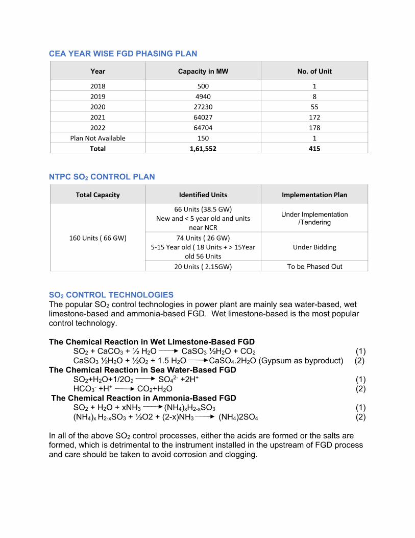
CEA YEAR WISE FGD PHASING PLAN
NTPC SO2 CONTROL PLAN
SO2 CONTROL TECHNOLOGIES The popular SO2 control technologies in power plant are mainly sea water-based, wet limestone-based and ammonia-based FGD. Wet limestone-based is the most popular control technology. The Chemical Reaction in Wet Limestone-Based FGD
SO2 + CaCO3 + ½ H2O CaSO3 ½H2O + CO2 (1) CaSO3 ½H2O + ½O2 + 1.5 H2O CaSO4.2H2O (Gypsum as byproduct) (2)
The Chemical Reaction in Sea Water-Based FGD SO2+H2O+1/2O2 SO42- +2H+ (1)
HCO3- +H+ CO2+H2O (2) The Chemical Reaction in Ammonia-Based FGD SO2 + H2O + xNH3 (NH4)xH2-xSO3 (1) (NH4)x H2-xSO3 + ½O2 + (2-x)NH3 (NH4)2SO4 (2) In all of the above SO2 control processes, either the acids are formed or the salts are formed, which is detrimental to the instrument installed in the upstream of FGD process and care should be taken to avoid corrosion and clogging.
Year Capacity in MW No. of Unit
2018 500 1 2019 4940 8 2020 27230 55 2021 64027 172 2022 64704 178
Plan Not Available 150 1 Total 1,61,552 415
Total Capacity Identified Units Implementation Plan
160 Units ( 66 GW)
66 Units (38.5 GW) New and < 5 year old and units
near NCR
Under Implementation /Tendering
74 Units ( 26 GW) 5-15 Year old ( 18 Units + > 15Year
old 56 Units Under Bidding
20 Units ( 2.15GW) To be Phased Out
The majority of plants in India are likely to adopt the worldwide proven wet limestone-based FGD technology. The addition of water in the slurry injection stage of wet FGD system promotes formation of acid gases, specifically sulfuric acid. The Wet FGD systems produce significant amount of acid gases due to the saturated flue gas conditions. The changes to the flue gas chemistry of FGD downstream gas requires changes in the CEMS system, particularly components in contact with the highly corrosive flue gas, to ensure long-term system availability and reduced maintenance issues. For running the FGD process efficiently, the SO2 analyzer is used upstream and downstream of the FGD and their accuracy is very critical as the addition of reagents depends on SO2 readings. The SO2 measurement in the downstream of FGD is particularly challenging due to lower SO2 content, acid mist, high moisture and salts. Condensing coolers can remove all SO2 in the downstream sample gas by dissolving the SO2 in the condensation. Perma Pure’s new Readi-GASS™ system addresses all of these challenges and in many cases allows the existing analyzers to accurately measure low SO2 levels. PERMA PURE Readi-GASS™ SYSTEM DESIGN The system contains two temperature-controlled zones mounted in an environmentally sealed, NEMA-4X, 24” x 10” x 5” housing. First Zone: High-Temperature Area The sample passes through a two-stage filtration process to remove particles as small as 0.1 micron. Acid mists, if present, are coalesced and then removed by an auto drain. The sample then passes through a Nafion™ dryer, which removes the moisture in the vapor phase. The initial portion of the dryer is heated above the sample dew point to prevent condensation and make drying more efficient. The high-temperature zone can be controlled at 80°C. Second Zone: Ambient Temperature Area In the second zone, the sample passes through the remainder of the dryer, further reducing the dew point to as low as 0°C or lower. A second Perma Pure PD series dryer is used to dry the incoming atmospheric air that is used to purge itself and the sample gas dryer thereby avoiding the requirement for instrument air

Perma Pure LLC • A Halma Company • [email protected] • www.permapure.com Telephone: 732-244-0010 • Toll Free: 800-337-3762 • Fax: 732-244-8140
1001 New Hampshire Ave., Lakewood, NJ 08701 USA
Figure 1: Readi-GASS™
The Readi-GASS™ System Design Offers Three Main Advantage for FGD CEMS
1) Excellent SO2 Retention The moisture removal in Readi-GASS™ is done using the Perma Pure exclusive Nafion™ membrane drying technology which removes the moisture in vapor phase thus not allowing highly water soluble SO2 gas to get dissolved in liquid water. The Readi-GASS™-based CEMS system allows accurate SO2 measurement in single digit and also in triple digit ppm.
2) Acid Mist and Ammonium Salt Removal The Readi-GASS™ design incorporates a two-stage filtration system which removes any acid mist and also particulates up to size 0.1 micron, thus saves the analyzer from corrosion due to the acid mist. A standalone ammonia scrubber upstream of the Readi-GASS™ will remove the ammonia thus avoiding the ammonia salt formation downstream and avoid sample line choking.
3) In-Situ Mounting Eliminates Heated Line Requirement The Readi-GASS™ system can be mounted near sampling point thus eliminating the need of high power consuming heated sample lines. Also, the heated line tends to pose cold spot challenges which gets reduced with in-situ mounting of Readi-GASS™. With low levels of SO2, any condensation can dissolve most of the SO2 in the sample gas making any cold spot in the heated sample line a major cause of inaccuracy.

Perma Pure LLC • A Halma Company • [email protected] • www.permapure.com Telephone: 732-244-0010 • Toll Free: 800-337-3762 • Fax: 732-244-8140
1001 New Hampshire Ave., Lakewood, NJ 08701 USA
Figure 2: CEMS System Configuration with Perma Pure Readi-GASS™ System
CONCLUSION AND PERSPECTIVE The above described Readi-GASS sample conditioning system will offer a reliable, accurate and economical sample conditioning solution for Flue Gas Desulphurization CEMS. Nafion™-based systems are proven worldwide and offer many advantages over conventionally designed CEMS systems. With the introduction of FGD in Indian thermal power plants, accurate and reliable CEMS system are very important as billions of dollars will be invested in pollution control technologies and reliable CEMS data will be the key enabler for cleaner environment in India. References
• Singh Gurdeep, (2017, Dec). Environmental Issues, Challenges and Innovations. Presented at the International Conference on Environmental Issues, Challenges and Innovations for Thermal Power Plants organized by CBIP, New Delhi, India
• Singh Narendra (2017, Dec). ROADMAP TO MEET NEW ENVIRONMENTAL NORMS
FOR TPS Issues and Challenges. Presented at the International Conference on Environmental Issues, Challenges and Innovations for Thermal Power Plants organized by CBIP, New Delhi, India