fhv/fhvt.แปดริ้วเครื่อง... · 2020-06-23 · corrosion resistant,...
TRANSCRIPT


2
FHV/FHVT flatlineflatlineflatlineflatline
HochleistungsluftkühlerForced convection unit air coolerEvaporadores cúbicos de tiro forzado
FHVT 602
FHV 422
FHVT 412

FHV/FHVT flatlineflatlineflatlineflatline
3
Einsatzbereich:● Für alle Sicherheitskältemittel.● Für Kühl- und Tiefkühlräumemit normaler Luftfeuchtigkeit (z. B.verpackte Ware in Supermärkten).● Temperaturbereich:
FHV: > 0 °C,FHVT: > –30 °C.
Besondere Merkmale:� Hochleistungswärmeaustau-scher mit geringem Innenvolu-men.� Ventilatoren mit Steckeran-schluss (nur FHV/T .0.).� Montage der Schutzgitter mitSchalldämpfungselementen.� Ventilatoren und Heizstäbe (nur FHVT) auf innen liegendeAnschlussdose verdrahtet (integrierter Kabelkanal).� Befestigungslöcher für Abtau-Sicherheitsthermostat (Zubehör).� Ablaufheizung nachträglichleicht montierbar (Zubehör).� Flache Aufhängeschiene ausCrNi-Stahl.
Sonderausführungen:● Lamellenblock mit Korrosions-schutz.● Wärmeaustauscher für Wasser-oder Solebetrieb.● Sonderventilatoren oderdrückende Version auf Anfrage.● -Ausführung auf Anfrage.
Zubehör:siehe Seite 12/13.
Application range:● For all safety refrigerants.● For cold storage and low tem-perature rooms with normal hu-midity (e.g. packed goods insupermarkets).● Temperature range:
FHV: > 0 °C,FHVT: > –30 °C.
Special features:� High efficiency heat exchangerwith small interior volume.� Fans with plug connection(only FHV/T .0.).� Fan guards mounted with sound absorbing elements.� Fans and heater rods (onlyFHVT) wired to internally mountedterminal box (integral cableconduit).� Mounting holes for defrostsafety thermostat (accessory).� Drain heater easy to install later(accessory).� Flat stainless steel mountingrail.
Special versions:● Coil block with protectionagainst corrosion.● Heat exchanger designed forwater or brine circulation.● Special fans or fans blowingthrough on request. ● Models on request.
Accessories:see page 12/13.
Campo de utilización:● Para fluidos frigoríficos de seguridad.● Para todas las cámaras frigoríficas y cá-maras de congelación, de humedad normal(p.e. productos embalados en supermerca-dos).● Temperaturas de utilización:
FHV: > 0 °C.FHVT: > –30 °C.
Características particulares:� Batería de gran rendimientocon un pequeño volumen interno.� Ventiladores con conexión por termina-les (solamente FHV/T .0.).� Montaje de las rejillas de protección conelementos de insonorización.� Ventiladores y resistencias de calor (soloFHVT) conexionados a la caja de bornas in-terna (cable integrado).� Agujeros de fijación para el termostatode seguridad de desescarche (accesorio).� Resistencia de silicona en desagüe conun acceso fácil (accesorio).� Soporte de anclaje en acero inoxidable.
Construcciones especiales:● Batería con protección contra corrosión.● Intercambiador con circuitos especialespara agua fría o glicolada.● Versión impelente bajo demanda.● Modelos bajo pedido.
Accesorios:Ver página 12/13.
� �
� �� � �

4
FHV/FHVT flatlineflatlineflatlineflatline
G+20
44
F35
D
375 min. G
322
Ø12
=
A
1170 =
1170**
A
= =
A
=
A
=
fh27
0905
a.dw
g
==
A
EC
B
C
C
B
C
C*
B
C*E*
C
B
C
B
R3/4"
R3/4"
R3/4"
R3/4" *
R3/4"
R3/4"
R3/4" **
FHV/T .22
R3/4" **
FHV/T .14
==
* FHV/T .03/ .13** FHV/T .23
88
88
8
M
M
M
M
M
fh27
0905
a.dw
g

5
FHV/FHVT flatlineflatlineflatlineflatline
Abmessungen, Rohrinhalte, GewichteDimensions, Tube volumes, Weights
Dimensiones, capacidad de los tubos, pesos
Typ Abmessungen in mm Rohrinhalte GewichteModel Dimensions in mm Tube volumes Weights
Modelo Dimensiones en mm Volumen interno PesosFHV FHVT
4.. 6.. 4.. 6..
FHV/FHVT A B C D E F G dm3 kg kg kg kg
401 601 702 420 – 350 – 430 200 1,8 14 13 14 13411 611 702 420 – 460 – 430 200 2,4 19 18 19 18421 621 1094 812 – 600 – 460 300 5,5 39 36 41 38402 602 1094 812 – 350 – 430 200 3,2 24 22 25 23412 612 1094 812 – 460 – 430 200 4,3 31 29 32 30422 622 1878 1596 798 600 – 460 300 10,5 78 71 82 75403 603 1486 1204 – 350 – 430 200 4,7 33 30 36 33413 613 1486 1204 – 460 – 430 250 6,2 43 40 46 43423 623 2662 2380 798 600 784 460 350 15,5 118 111 122 115404 604 1878 1596 – 350 – 430 200 6,1 44 40 47 43414 614 1878 1596 798 460 – 430 250 8,2 57 53 60 56406 606 2662 2380 798 350 784 430 250 8,7 64 60 70 66416 616 2662 2380 798 460 784 430 300 11,6 83 79 85 83
Elektrische AnschlusswerteElectrical loads
Características eléctricas
Typ Ventilatoren El. Abtauheizung FHV Elektr. Abtauheizung FHVTModel Fans (Zubehör) Electric defrost FHVT
Modelo Ventiladores Electric defrost FHV Desescarche eléctrico FHVT(accessory)
Desescarche eléctrico FHV(accesorio)
Anz.�� Stromart Leistung Stromaufn. Drehzahl Block Gesamt Block Schale GesamtNbr.�� Type of curr. Input cap. Curr. cons. No. of rev. Coil Total Coil Drain pan TotalNo�� Tensión Potencia Intensidad r.p.m. Batería Total Batería Bandeja Total
FHV/FHVT V, 50/60 Hz W A min–1 W W W W W
401 601 1�254 ~ 230 86/80 0,62/0,55 1300/1550 2� 250 500 2� 440 440 1320411 611 1�300 ~ 230 78/103 0,35/0,45 1350/1520 3� 250 750 3� 440 440 1760421 621 1�445 3 ~ 400 � 320/500 0,74/0,88 1390/1630 4� 400 1600 4� 730 730 3650402 602 2�254 ~ 230 86/80 0,62/0,55 1300/1550 2� 400 800 2� 730 730 2190412 612 2�300 ~ 230 78/103 0,35/0,45 1350/1520 3� 400 1200 3� 730 730 2920422 622 2�445 3 ~ 400 � 320/500 0,74/0,88 1390/1630 4� 850 3400 4�1310 1310 6550403 603 3�254 ~ 230 86/80 0,62/0,55 1300/1550 2� 600 1200 2�1030 1030 3090413 613 3�300 ~ 230 78/103 0,35/0,45 1350/1520 3� 600 1800 3�1030 1030 4120423 623 3�445 3 ~ 400 � 320/500 0,74/0,88 1390/1630 4�1300 5200 4�1890 1890 9450404 604 4�254 ~ 230 86/80 0,62/0,55 1300/1550 2� 850 1700 2�1310 1310 3930414 614 4�300 ~ 230 78/103 0,35/0,45 1350/1520 3� 850 2550 3�1310 1310 5240406 606 6�254 ~ 230 86/80 0,62/0,55 1300/1550 2�1300 2600 2�1890 1890 5670416 616 6�300 ~ 230 78/103 0,35/0,45 1350/1520 3�1300 3900 3�1890 1890 7560

FHV/FHVT flatlineflatlineflatlineflatline
6
AusführungDesign Construcción
Gehäuse:● Aluminium, weiß pulverbeschich-tet, korrosionsbeständig, schlag-und kratzfest.● Tropfschale mit Staublech zurVermeidung von Schwitzwasser-bildung.● Ablaufstutzen R3/4“ aus Polyamid.
Lamellenblock:● Innen berippte Kupferrohre � 12mm aus Cu-DHP.● Rohrabstand 35 mm x 35 mm,fluchtend.● Aluminium-Lamellen, Dicke 0,30mm, Lamellenabstand 4,0 (FHV/T 4..)bzw. 6,0 (FHV/T 6..) mm.● Lötanschlüsse aus Kupferrohrnach DIN 8905-1, verschlossen.● Schutzgasfüllung.● Druck- und Dichtheitsprüfung mitLuft 27,5 bar Überdruck in Wasserentsprechend DruckbehV und TRB801, Absatz 14 (Prüfgr. II) und 522 .● Reinheit entsprechend DIN 8964-3.
Ventilatoren:● FHV/T .0.: Axialventilatoren mitInnenläufermotor, Spaltpolmotor 230 V, 50/60 Hz mit Thermokontakt,intern verdrahtet, Flügel � 254 mm.● FHV/T .1.: Axialventilatoren mitAußenläufermotor, Einphasenmotor230 V, 50/60 Hz mit Thermokontakt,intern verdrahtet, Flügel � 300 mm.● FHV/T .2.: Axialventilatoren mitAußenläufermotor, Drehstrommotor400 V, 50/60 Hz mit Thermokontakt,auf Klemmen verdrahtet, Flügel � 445 mm.● Elektrische Ausführung entspre-chend EN 60335-1:1995, .● Schutzart nach EN 60034-5:1995:FHV/T .0.: IP 42,FHV/T .1.: IP 44,FHV/T .2.: IP 54.● Einsatzbereich:RE 251 N: –10 °C bis +40 °C (FHV .0.),RE 251 T: –35 °C bis +20 °C (FHVT .0.),S4E 300S: –35 °C bis +40 °C (FHV/T .1.),S4D 450S: –50 °C bis +50 °C (FHV/T .2.).
Abtauheizung:● Elektrische Heizstäbe 230 V ausCrNi-Mantelrohr � 8,5 mm (FHVT).● Elektrische Heizstäbe 230 V ausCrNi-Mantelrohr � 12 mm alsZubehör (FHV).● Elektrische Ausführung ent-sprechend den VDE-Bestimmun-gen, .
Housing:● Aluminium, white powder coated,corrosion resistant, impact andscratchproof.● Drain pan with intermediate sheetto avoid condensation.● Drain union R3/4“ made ofpolyamid.
Finned coil block:● Internally grooved copper tubes � 12 mm, made of Cu-DHP.● Tube spacing 35 mm x 35 mm in-line.● Aluminium fins, thickness 0.30mm, fin spacing 4.0 (FHV/T 4..) resp.6.0 (FHV/T 6..) mm.● Copper tube soldering connectionsaccording to DIN 8905-1, closed.● Protective gas charge.● Pressure and leaktest with air 27.5bar over-pressure under water ac-cording to DruckbehV (pressure ves-sel regulation) and TRB 801, para-graph 14 (Prüfgr. II) and 522 .● Cleanness according to DIN 8964-3.
Fan assemblies:● FHV/T .0.: Axial fans with internalrotor motor, shaded pole motor 230 V, 50/60 Hz with internally wiredthermal contact, fan � 254 mm.● FHV/T .1.: Axial fans with externalrotor motor, single-phase motor 230 V, 50/60 Hz with internally wiredthermal contact, fan � 300 mm.● FHV/T .2.: Axial fans with externalrotor motor, three-phase motor 400 V, 50/60 Hz with thermal contactwired to terminals, fan � 445 mm.● Electrical design according to EN60335-1:1995, .● Protection class according toEN 60034-5:1995:FHV/T .0.: IP 42,FHV/T .1.: IP 44,FHV/T .2.: IP 54.● Application range:RE 251 N: –10 °C to +40 °C (FHV .0.),RE 251 T: –35 °C to +20 °C (FHVT .0.),S4E 300S: –35 °C to +40 °C (FHV/T .1.),S4D 450S: –50 °C to +50 °C (FHV/T .2.).
Defrost heating:● Electric heater rods 230 V made ofCrNi-sleeve tube � 8.5 mm (FHVT).● Electric heater rods 230 V made ofCrNi-sleeve tube � 12 mm suppliedas accessory (FHV).● Electrical design according to VDEregulations, .
Carcasa:● De aluminio, revestida con polvo electro-estático blanco RAL 9010, resistente a lacorrosión, a los golpes y a las ralladuras.● Bandeja de desagüe con sobrebandejaque evita la formación de agua de conden-sación.● Conexión de desagüe de 3/4“ realizada enpolyamida.
Batería:● Tubos de cobre internamente ranurados(Ø 12 mm, en Cu-DHP).● Distancia entre ejes de tubos de 35 mm x35 mm alineados.● Aletas de aluminio con un espesor de0,30 mm, separación de aletas de 4 (FHV/T4...) y 6 (FHV/T 6...) mm. Respectivamente.● Conexiones para soldar en tubo de cobresegún norma DIN 8905-1.● Sellado con gas de protección.● Prueba de presión y estanqueidad rea-lizada en agua con aire a 27,5 bar de pre-sión, conforme a la Druckbeh V y TRB 801párrafo 14 (Prüfgr. II) y 522 .● Limpieza según norma DIN 8964-3.
Ventiladores:● FHV/T .0.: ventiladores helicoidales conmotores de rotor interno, motores de variospolos 230 V, 50/60 Hz con termo-contacto in-corporado y conectado, hélice de Ø 254mm.● FHV/T .1.: ventiladores helicoidales conmotores de rotor externo, motores monofá-sicos 230 V, 50/60 Hz con termo-contacto in-corporado y conectado, hélice de Ø 300mm.● FHV/T .2.: ventiladores helicoidales conmotores de rotor externo, motores trifásicos400 V, 50/60 Hz con termo-contacto conec-tado en bornas, hélice de Ø 445 mm.● Construcción eléctrica según norma VDE0530, .● Clase de protección de acuerdo con lanorma EN 60034-5: 1995FHV/T .0.: IP 42,FHV/T .1.: IP 44,FHV/T .2.: IP 54.● Campo de funcionamiento:RE 251 N: –10 °C hasta +40 °C (FHV .0.),RE 251 T: –35 °C hasta +20 °C (FHVT .0.),S4E 300S: –35 °C hasta +40 °C (FHVT .1.).S4D 450S: –50 °C hasta +50 °C (FHV/T .2.).
Desescarche:● Resistencias eléctricas 230 V en CrNi- virola Ø 8,5 mm (FHVT).● Resistencias eléctricas 230 V en CrNi-virola Ø 12 mm suministrado como acceso-rio (FHV).● Construcciones eléctricas según la nor-mativa VDE, .
FHV/FHVT flatlineflatlineflatlineflatline
7
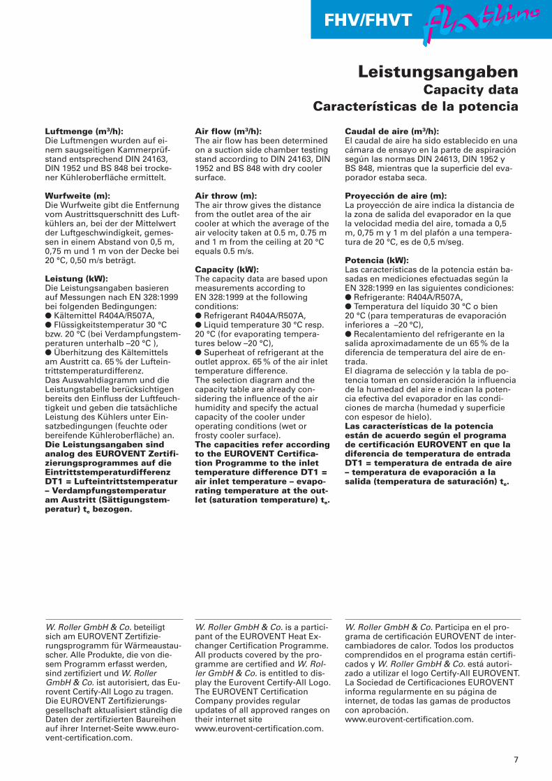
Luftmenge (m3/h):Die Luftmengen wurden auf ei-nem saugseitigen Kammerprüf-stand entsprechend DIN 24163,DIN 1952 und BS 848 bei trocke-ner Kühleroberfläche ermittelt.
Wurfweite (m):Die Wurfweite gibt die Entfernungvom Austrittsquerschnitt des Luft-kühlers an, bei der der Mittelwertder Luftgeschwindigkeit, gemes-sen in einem Abstand von 0,5 m,0,75 m und 1 m von der Decke bei20 °C, 0,50 m/s beträgt.
Leistung (kW):Die Leistungsangaben basierenauf Messungen nach EN 328:1999bei folgenden Bedingungen:● Kältemittel R404A/R507A,● Flüssigkeitstemperatur 30 °Cbzw. 20 °C (bei Verdampfungstem-peraturen unterhalb –20 °C ),● Überhitzung des Kältemittelsam Austritt ca. 65 % der Luftein-trittstemperaturdifferenz.Das Auswahldiagramm und dieLeistungstabelle berücksichtigenbereits den Einfluss der Luftfeuch-tigkeit und geben die tatsächlicheLeistung des Kühlers unter Ein-satzbedingungen (feuchte oderbereifende Kühleroberfläche) an.Die Leistungsangaben sindanalog des EUROVENT Zertifi-zierungsprogrammes auf dieEintrittstemperaturdifferenzDT1 = Lufteintrittstemperatur– Verdampfungstemperaturam Austritt (Sättigungstem-peratur) te bezogen.
Air flow (m3/h):The air flow has been determinedon a suction side chamber testingstand according to DIN 24163, DIN1952 and BS 848 with dry coolersurface.
Air throw (m):The air throw gives the distancefrom the outlet area of the air cooler at which the average of theair velocity taken at 0.5 m, 0.75 mand 1 m from the ceiling at 20 °Cequals 0.5 m/s.
Capacity (kW):The capacity data are based uponmeasurements according to EN 328:1999 at the followingconditions:● Refrigerant R404A/R507A,● Liquid temperature 30 °C resp.20 °C (for evaporating tempera-tures below –20 °C),● Superheat of refrigerant at theoutlet approx. 65 % of the air inlettemperature difference.The selection diagram and thecapacity table are already con-sidering the influence of the airhumidity and specify the actualcapacity of the cooler underoperating conditions (wet orfrosty cooler surface).The capacities refer accordingto the EUROVENT Certifica-tion Programme to the inlettemperature difference DT1 =air inlet temperature – evapo-rating temperature at the out-let (saturation temperature) te.
Caudal de aire (m3/h):El caudal de aire ha sido establecido en unacámara de ensayo en la parte de aspiraciónsegún las normas DIN 24613, DIN 1952 y BS 848, mientras que la superficie del eva-porador estaba seca.
Proyección de aire (m):La proyección de aire indica la distancia dela zona de salida del evaporador en la quela velocidad media del aire, tomada a 0,5m, 0,75 m y 1 m del plafón a una tempera-tura de 20 °C, es de 0,5 m/seg.
Potencia (kW):Las características de la potencia están ba-sadas en mediciones efectuadas según laEN 328:1999 en las siguientes condiciones:● Refrigerante: R404A/R507A,● Temperatura del líquido 30 °C o bien 20 °C (para temperaturas de evaporacióninferiores a –20 °C),● Recalentamiento del refrigerante en lasalida aproximadamente de un 65 % de ladiferencia de temperatura del aire de en-trada.El diagrama de selección y la tabla de po-tencia toman en consideración la influenciade la humedad del aire e indican la poten-cia efectiva del evaporador en las condi-ciones de marcha (humedad y superficiecon espesor de hielo).Las características de la potenciaestán de acuerdo según el programade certificación EUROVENT en que ladiferencia de temperatura de entradaDT1 = temperatura de entrada de aire– temperatura de evaporación a lasalida (temperatura de saturación) te.
LeistungsangabenCapacity data
Características de la potencia
W. Roller GmbH & Co. beteiligt sich am EUROVENT Zertifizie-rungsprogramm für Wärmeaustau-scher. Alle Produkte, die von die-sem Programm erfasst werden,sind zertifiziert und W. RollerGmbH & Co. ist autorisiert, das Eu-rovent Certify-All Logo zu tragen.Die EUROVENT Zertifizierungs-gesellschaft aktualisiert ständig dieDaten der zertifizierten Baureihenauf ihrer Internet-Seite www.euro-vent-certification.com.
W. Roller GmbH & Co. is a partici-pant of the EUROVENT Heat Ex-changer Certification Programme.All products covered by the pro-gramme are certified and W. Rol-ler GmbH & Co. is entitled to dis-play the Eurovent Certify-All Logo.The EUROVENT CertificationCompany provides regular updates of all approved ranges ontheir internet site www.eurovent-certification.com.
W. Roller GmbH & Co. Participa en el pro-grama de certificación EUROVENT de inter-cambiadores de calor. Todos los productoscomprendidos en el programa están certifi-cados y W. Roller GmbH & Co. está autori-zado a utilizar el logo Certify-All EUROVENT.La Sociedad de Certificaciones EUROVENTinforma regularmente en su página de internet, de todas las gamas de productoscon aprobación.www.eurovent-certification.com.

FHV/FHVT flatlineflatlineflatlineflatline
8
Die Angaben in obiger Tabellebasieren auf Messungen beiR404A/R507A und Betrieb derVentilatoren mit 50 Hz.
Daten bei 60 HzBei Betrieb der Ventilatoren mit 60 Hzverändern sich diese Daten wie folgt:Leistung: Tabellenwert �1,09,Luftmenge: Tabellenwert �1,13,Schallleistungspegel: Tabellenwert +3.
Leistungen bei R134a und R22Bei Anwendung dieser Kältemittelwird die Katalogleistung mit demFaktor f des nachfolgenden Dia-gramms multipliziert.
The data in the table above are based upon measurements withR404A/R507A and fans operating on 50 Hz supply.
Data on 60 HzWith fans operating on 60 Hz the datawill change as follows:Capacity: table rating �1.09,Air flow: table rating �1.13,Sound power level: table rating +3.
Capacities with R134a and R22When using these refrigerants thecatalogue rated capacity has to bemultiplied with the factor f of thefollowing diagram.
Las características de la tabla se ba-san en medidas con R404A/R507A ycon los ventiladores a 50 Hz.
Características con 60 HzEn funcionamiento de los ventilado-res a 60 Hz, las características se ob-tendrán de la siguiente manera:Potencia frig.: valor de la tabla �1,09,Caudal aire: valor de la tabla �1,13,Nivel sonoro: valor de la tabla +3.
Potencias con R134a, R22Para el uso con estos refrigerantes, lapotencia del catálogo deberá ser mul-tiplicada por el factor de corrección fdel siguiente diagrama.
401–423 Lamellenabstand 4,0 mm Fin spacing 4.0 mm Separación de aletas 4,0 mm
Leistung Anschlüsse
TypCapacity Connections
ModelPotencia Conexiones
Modelo te = –8 °C te = –25 °C Eintritt AustrittInlet Outlet
DT1 = 8 K DT1 = 7 K Entrada Salida
FHV/FHVT kW kW m2 m3/h m dB(A) dB(A)** � mm � mm
401 1,73 1,26 7,4 930 4 63 50 12* 15411 2,41 1,76 9,9 1500 5 70 57 12* 18402 3,35 2,44 14,9 1860 6 66 53 12* 18412 4,89 3,57 19,8 3000 7 73 59 12* 22403 4,91 3,58 22,3 2790 7 68 54 12* 22404 6,55 4,78 29,8 3720 8 69 55 12* 22421 6,75 4,92 26,4 4300 9 78 64 12* 22413 7,41 5,40 29,8 4500 10 75 61 12* 22414 9,75 7,11 39,7 6000 11 76 62 15* 28406 10,00 7,33 44,7 5580 11 71 56 15* 28422 13,50 9,84 52,9 8600 11 81 66 15* 28416 14,70 10,70 59,6 9000 12 78 63 15* 28423 19,00 13,90 79,5 12900 13 83 68 15* 35
Luft
men
ge
Air
flo
wC
aud
al d
e ai
re
Ob
erfl
äch
eS
urf
ace
Su
per
fici
e
Wu
rfw
eite
Air
th
row
Pro
yecc
ión
air
e
Sch
allle
istu
ng
speg
elS
ou
nd
po
wer
leve
lP
ote
nci
a so
no
ra
Sch
alld
ruck
pege
lS
ound
pre
ssur
e le
vel
Pres
ión
sono
ra
** Mittl. Schalldruckpegel in 1 m Abstand im Freifeld (halbkugelförmige Schallausbreitung)** Mean sound pressure level at a distance of 1 m in semi-reverberant field** Presión sonora media a 1 m de distancia en campo semi-reverberante
* Mehrfacheinspritzung mit Schraderventil am Austritt* Multiple injection with Schrader valve at the outlet* Inyección múltiple a la salida de la válvula
VerdampfungstemperaturEvaporation temperature
Temperatura de evaporación
Fakt
or,
Fact
or,
Fact
or
f

FHV/FHVT flatlineflatlineflatlineflatline
9
AuswahldiagrammSelection DiagramDiagramme de sélection
FHV 401-423 FHVT 401-423Anwendungsbereich:Räume über 0 ˚CApplication range: Rooms above 0 ˚CSecteur d'application: Chambres de plus de 0 ˚C
Anwendungsbereich:Räume bis -30 ˚CApplication range: Rooms to -30 ˚CSecteur d'application: Chambres à -30 ˚C
fhv4
r507
.ai
ReifgrenzeRime limitLimite de givre
401
411
402
403/412
404/421413406/414422
423
0,15
0,2
0,3
0,40,50,60,70,81,0
1,5
2
3
45678
10
15
20
30
4050
[kW]
Leis
tun
gC
apac
ity
Puis
san
ce
416
DT1 = 6 K13 K 10 K 9 K 8 K 7 K11 K12 K5
[˚C]0
-5
-10
-15
-20
-25
-30
-35
Verd
amp
fun
gst
emp
erat
ur
Eva
po
rati
on
tem
per
atu
reTe
mp
érat
ure
d'é
vap
ora
tio
nAuswahldiagrammSelection diagramTabla de selección
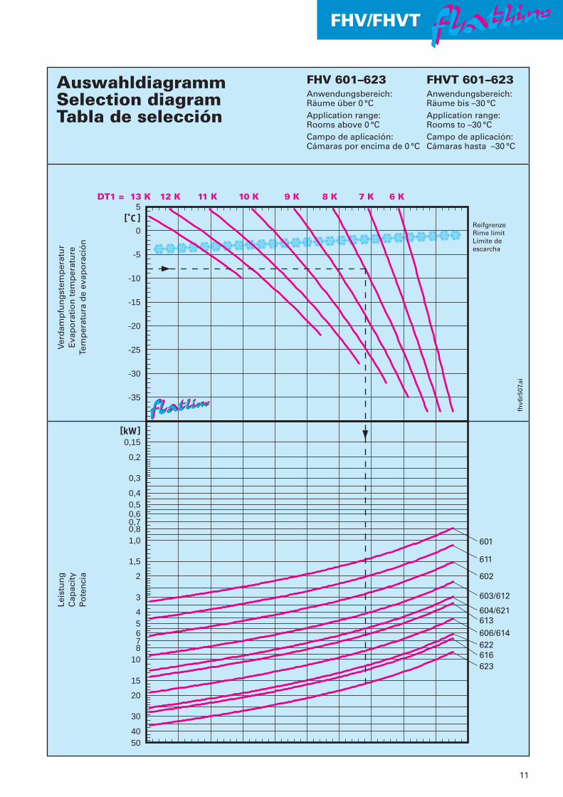
FHV 401–423Anwendungsbereich:Räume über 0 °CApplication range:Rooms above 0 °CCampo de aplicación:Cámaras por encima de 0 °C
Verd
amp
fun
gst
emp
erat
ur
Eva
po
rati
on
tem
per
atu
reTe
mp
erat
ura
de
evap
ora
ció
n
Leis
tun
gC
apac
ity
Po
ten
cia
ReifgrenzeRime limitLímite de escarcha
FHVT 401–423Anwendungsbereich:Räume bis –30 °CApplication range:Rooms to –30 °CCampo de aplicación:Cámaras hasta –30 °C

10
FHV/FHVT flatlineflatlineflatlineflatline
601–623 Lamellenabstand 6,0 mm Fin spacing 6.0 mm Separación de aletas 6,0 mm
Leistung Anschlüsse
TypCapacity Connections
ModelPotencia Conexiones
Modelo te = –8 °C te = –25 °C Eintritt AustrittInlet Outlet
DT1 = 8 K DT1 = 7 K Entrada Salida
FHV/FHVT kW kW m2 m3/h m dB(A) dB(A)** � mm � mm
601 1,46 1,06 5,2 980 4 63 50 12* 15611 2,03 1,48 6,9 1560 5 70 57 12* 18602 2,81 2,05 10,3 1960 6 66 53 12* 18612 4,11 3,00 13,8 3120 7 73 59 12* 22603 4,13 3,01 15,5 2940 7 68 54 12* 22604 5,51 4,02 20,7 3920 8 69 55 12* 22621 5,67 4,13 18,4 4400 9 78 64 12* 22613 6,23 4,54 20,7 4680 10 75 61 12* 22614 8,19 5,98 27,6 6240 11 76 62 15* 28606 8,44 6,16 31,0 5880 11 71 56 15* 28622 11,30 8,27 36,8 8800 11 81 66 15* 28616 12,30 8,99 41,4 9360 12 78 63 15* 28623 16,00 11,70 55,2 13200 13 83 68 15* 35
Luft
men
ge
Air
flo
wC
aud
al d
e ai
re
Ob
erfl
äch
eS
urf
ace
Su
per
fici
e
Wu
rfw
eite
Air
th
row
Pro
yecc
ión
air
e
Sch
allle
istu
ng
speg
elS
ou
nd
po
wer
leve
lP
ote
nci
a so
no
ra
Sch
alld
ruck
pege
lS
ound
pre
ssur
e le
vel
Pres
ión
sono
ra
** Mittl. Schalldruckpegel in 1 m Abstand im Freifeld (halbkugelförmige Schallausbreitung)** Mean sound pressure level at a distance of 1 m in semi-reverberant field** Presión sonora media a 1 m de distancia en campo semi-reverberante
* Mehrfacheinspritzung mit Schraderventil am Austritt* Multiple injection with Schrader valve at the outlet* Inyección múltiple a la salida de la válvula
Die Angaben in obiger Tabellebasieren auf Messungen beiR404A/R507A und Betrieb derVentilatoren mit 50 Hz.
Daten bei 60 HzBei Betrieb der Ventilatoren mit 60 Hzverändern sich diese Daten wie folgt:Leistung: Tabellenwert �1,09,Luftmenge: Tabellenwert �1,13,Schallleistungspegel: Tabellenwert +3.
Leistungen bei R134a und R22Bei Anwendung dieser Kältemittelwird die Katalogleistung mit demFaktor f des nachfolgenden Dia-gramms multipliziert.
The data in the table above are based upon measurements withR404A/R507A and fans operating on 50 Hz supply.
Data on 60 HzWith fans operating on 60 Hz the datawill change as follows:Capacity: table rating �1.09,Air flow: table rating �1.13,Sound power level: table rating +3.
Capacities with R134a and R22When using these refrigerants thecatalogue rated capacity has to bemultiplied with the factor f of thefollowing diagram.
Las características de la tabla se ba-san en medidas con R404A/R507A ycon los ventiladores a 50 Hz.
Características con 60 HzEn funcionamiento de los ventilado-res a 60 Hz, las características se ob-tendrán de la siguiente manera:Potencia frig.: valor de la tabla �1,09,Caudal aire: valor de la tabla �1,13,Nivel sonoro: valor de la tabla +3.
Potencias con R134a, R22Para el uso con estos refrigerantes, lapotencia del catálogo deberá ser mul-tiplicada por el factor de corrección fdel siguiente diagrama.
VerdampfungstemperaturEvaporation temperature
Temperatura de evaporación
Fakt
or,
Fact
or,
Fact
or
f
11
FHV/FHVT flatlineflatlineflatlineflatline
AuswahldiagrammSelection DiagramDiagramme de sélection
FHV 601-623 FHVT 601-623Anwendungsbereich:Räume über 0 ˚CApplication range: Rooms above 0 ˚CSecteur d'application: Chambres de plus de 0 ˚C
Anwendungsbereich:Räume bis -30 ˚CApplication range: Rooms to -30 ˚CSecteur d'application: Chambres à -30 ˚C
fhv6
r507
.ai
ReifgrenzeRime limitLimite de givre
601
611
602
603/612
604/621613606/614622
623
0,15
0,2
0,3
0,40,50,60,70,81,0
1,5
2
3
45678
10
15
20
30
4050
[kW]
Leis
tun
gC
apac
ity
Puis
san
ce
616
DT1 = 6 K13 K 10 K 9 K 8 K 7 K11 K12 K5
[˚C]0
-5
-10
-15
-20
-25
-30
-35
Verd
amp
fun
gst
emp
erat
ur
Eva
po
rati
on
tem
per
atu
reTe
mp
érat
ure
d'é
vap
ora
tio
nAuswahldiagrammSelection diagramTabla de selección
FHV 601–623Anwendungsbereich:Räume über 0 °CApplication range:Rooms above 0 °CCampo de aplicación:Cámaras por encima de 0 °C
Verd
amp
fun
gst
emp
erat
ur
Eva
po
rati
on
tem
per
atu
reTe
mp
erat
ura
de
evap
ora
ció
n
Leis
tun
gC
apac
ity
Po
ten
cia
ReifgrenzeRime limitLímite de escarcha
FHVT 601–623Anwendungsbereich:Räume bis –30 °CApplication range:Rooms to –30 °CCampo de aplicación:Cámaras hasta –30 °C
Typ Anzahl/Satz Leistung TypModel Number/Set Wattage Model
Modelo No/juego Potencia Referencia
FHV W
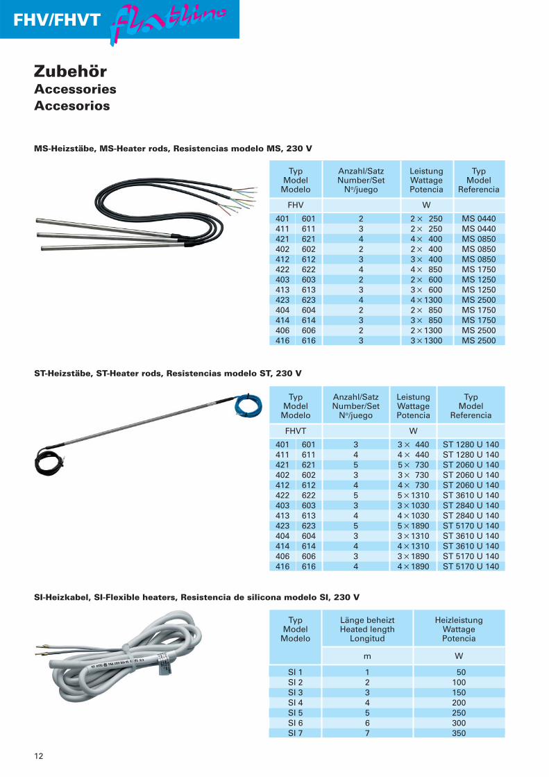
401 601 2 2 � 250 MS 0440411 611 3 2� 250 MS 0440421 621 4 4� 400 MS 0850402 602 2 2� 400 MS 0850412 612 3 3� 400 MS 0850422 622 4 4� 850 MS 1750403 603 2 2� 600 MS 1250413 613 3 3� 600 MS 1250423 623 4 4�1300 MS 2500404 604 2 2� 850 MS 1750414 614 3 3� 850 MS 1750406 606 2 2�1300 MS 2500416 616 3 3�1300 MS 2500
FHV/FHVT flatlineflatlineflatlineflatline
12
Typ Länge beheizt HeizleistungModel Heated length Wattage
Modelo Longitud Potencia
m W
SI 1 1 50SI 2 2 100SI 3 3 150SI 4 4 200SI 5 5 250SI 6 6 300SI 7 7 350
Typ Anzahl/Satz Leistung TypModel Number/Set Wattage Model
Modelo No/juego Potencia Referencia
FHVT W
401 601 3 3 � 440 ST 1280 U 140411 611 4 4 � 440 ST 1280 U 140421 621 5 5� 730 ST 2060 U 140402 602 3 3� 730 ST 2060 U 140412 612 4 4� 730 ST 2060 U 140422 622 5 5�1310 ST 3610 U 140403 603 3 3�1030 ST 2840 U 140413 613 4 4�1030 ST 2840 U 140423 623 5 5�1890 ST 5170 U 140404 604 3 3�1310 ST 3610 U 140414 614 4 4�1310 ST 3610 U 140406 606 3 3�1890 ST 5170 U 140416 616 4 4�1890 ST 5170 U 140
MS-Heizstäbe, MS-Heater rods, Resistencias modelo MS, 230 V
ST-Heizstäbe, ST-Heater rods, Resistencias modelo ST, 230 V
SI-Heizkabel, SI-Flexible heaters, Resistencia de silicona modelo SI, 230 V
ZubehörAccessoriesAccesorios

FHV/FHVT flatlineflatlineflatlineflatline
13
Fest eingestellterSchaltkontakt,öffnend +25 °C,schließend +3,5 °C.Schaltleistung bei�230 V, 50 Hz:ohmsch Imax 25 A,induktiv Imax 5 A.Schutzart IP 44. Anschlusskabel2-adrig, 75 cm lang.
Fixed break point,disconnects at +25 °C,connects at +3.5 °C.Switch capacity at�230 V, 50 Hz:ohmic Imax 25 A,inductive Imax 5 A.Protection class:IP 44. Connection cabletwo cores, 75 cm long.
Punto de corte fijo a+25 °C, conexión a+3,5 °C.Potencia de ruptura a�230 V, 50 Hz:ohmica Imax 25 A,inductiva Imax 5 A.Tipo de protección: IP 44.Cable de conexión aconductores de 75 cm de longitud.
Abtau-Sicherheitsthermostat, Defrost safety thermostat, Termostato de seguridad para desescarche
Ausführung TA:Aluminium, weißpulverbeschichtet,mit Montagematerial.
Design TA:Aluminium, whitepowder coated,including mountingmaterial.
Construcción TA:De aluminio, reves-tida con polvo elec-troestático blanco,con fijaciones.
Textilschlauch-Anschlüsse, Textil hose connections, Conexión para manga textil
ZubehörAccessoriesAccesorios
FHVT 412+TA
Auf Anfrage. On request. Bajo demanda.
Nachleiträder für Axialventilatoren, Streamers for axial fans, Banderola para ventiladores axiales.
Typ Anzahl TypModel Number Model
Modelo Número Referencia
FHVT TA
401 601 – –411 611 1 300402 602 – –412 612 2 300421 621 1 450403 603 – –413 613 3 300404 604 – –414 614 4 300406 606 – –416 616 6 300422 622 2 450423 623 3 450
14
FHV/FHVT flatlineflatlineflatlineflatline
Schaltpläne, Wiring diagrams, Esquemas de cableado
270.
902.
04
270.
903.
04
270.
907.
04
Typ AnzahlModel Number
Modelo Número
FHV E1–E3
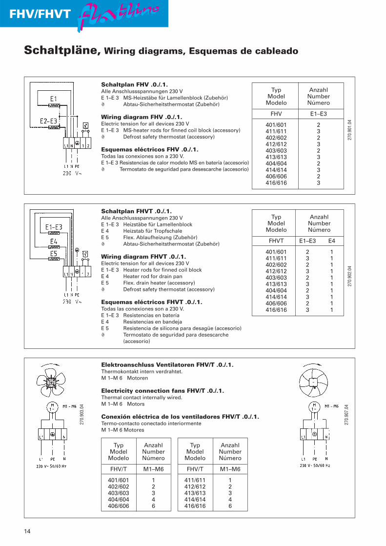
401/601 2411/611 3402/602 2412/612 3403/603 2413/613 3404/604 2414/614 3406/606 2416/616 3
Schaltplan FHV .0./.1.Alle Anschlussspannungen 230 VE 1–E 3 MS-Heizstäbe für Lamellenblock (Zubehör)� Abtau-Sicherheitsthermostat (Zubehör)
Wiring diagram FHV .0./.1.Electric tension for all devices 230 VE 1–E 3 MS-heater rods for finned coil block (accessory)� Defrost safety thermostat (accessory)
Esquemas eléctricos FHV .0./.1.Todas las conexiones son a 230 V.E 1–E 3 Resistencias de calor modelo MS en batería (accesorio)� Termostato de seguridad para desescarche (accesorio)
Schaltplan FHVT .0./.1.Alle Anschlussspannungen 230 VE 1–E 3 Heizstäbe für LamellenblockE 4 Heizstab für TropfschaleE 5 Flex. Ablaufheizung (Zubehör)� Abtau-Sicherheitsthermostat (Zubehör)
Wiring diagram FHVT .0./.1.Electric tension for all devices 230 VE 1–E 3 Heater rods for finned coil blockE 4 Heater rod for drain panE 5 Flex. drain heater (accessory)� Defrost safety thermostat (accessory)
Esquemas eléctricos FHVT .0./.1.Todas las conexiones son a 230 V.E 1–E 3 Resistencias en bateríaE 4 Resistencias en bandejaE 5 Resistencia de silicona para desagüe (accesorio)� Termostato de seguridad para desescarche
(accesorio)
Typ AnzahlModel Number
Modelo Número
FHVT E1–E3 E4
401/601 2 1411/611 3 1402/602 2 1412/612 3 1403/603 2 1413/613 3 1404/604 2 1414/614 3 1406/606 2 1416/616 3 1
Typ AnzahlModel Number
Modelo Número
FHV/T M1–M6
401/601 1402/602 2403/603 3404/604 4406/606 6
Typ AnzahlModel Number
Modelo Número
FHV/T M1–M6
411/611 1412/612 2413/613 3414/614 4416/616 6
270.
901.
04
Elektroanschluss Ventilatoren FHV/T .0./.1.Thermokontakt intern verdrahtet.M 1–M 6 Motoren
Electricity connection fans FHV/T .0./.1.Thermal contact internally wired.M 1–M 6 Motors
Conexión eléctrica de los ventiladores FHV/T .0./.1.Termo-contacto conectado interiormenteM 1–M 6 Motores
15
FHV/FHVT flatlineflatlineflatlineflatline
Schaltpläne, Wiring diagrams, Esquemas de cableado
FH 2
70.2
52.0
627
0.25
0.04
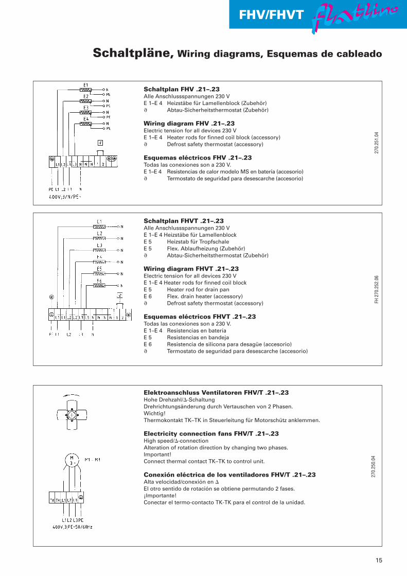
Schaltplan FHV .21–.23Alle Anschlussspannungen 230 VE 1–E 4 Heizstäbe für Lamellenblock (Zubehör)� Abtau-Sicherheitsthermostat (Zubehör)
Wiring diagram FHV .21–.23Electric tension for all devices 230 VE 1–E 4 Heater rods for finned coil block (accessory)� Defrost safety thermostat (accessory)
Esquemas eléctricos FHV .21–.23Todas las conexiones son a 230 V.E 1–E 4 Resistencias de calor modelo MS en batería (accesorio)� Termostato de seguridad para desescarche (accesorio)
Schaltplan FHVT .21–.23Alle Anschlussspannungen 230 VE 1–E 4 Heizstäbe für LamellenblockE 5 Heizstab für TropfschaleE 5 Flex. Ablaufheizung (Zubehör)� Abtau-Sicherheitsthermostat (Zubehör)
Wiring diagram FHVT .21–.23Electric tension for all devices 230 VE 1–E 4 Heater rods for finned coil blockE 5 Heater rod for drain panE 6 Flex. drain heater (accessory)� Defrost safety thermostat (accessory)
Esquemas eléctricos FHVT .21–.23Todas las conexiones son a 230 V.E 1–E 4 Resistencias en bateríaE 5 Resistencias en bandejaE 6 Resistencia de silicona para desagüe (accesorio)� Termostato de seguridad para desescarche (accesorio)
Elektroanschluss Ventilatoren FHV/T .21–.23Hohe Drehzahl/�-SchaltungDrehrichtungsänderung durch Vertauschen von 2 Phasen. Wichtig!Thermokontakt TK–TK in Steuerleitung für Motorschütz anklemmen.
Electricity connection fans FHV/T .21–.23High speed/�-connectionAlteration of rotation direction by changing two phases.Important!Connect thermal contact TK–TK to control unit.
Conexión eléctrica de los ventiladores FHV/T .21–.23Alta velocidad/conexión en �El otro sentido de rotación se obtiene permutando 2 fases.¡Importante!Conectar el termo-contacto TK-TK para el control de la unidad.
270.
251.
04

Walter Roller GmbH & Co.Fábrica de aparatos frigoríficosy de climatizaciónLindenstrasse 27–3170839 Gerlingen
Apartado de correos 10 033070828 Gerlingencerca de StuttgartAlemaniaTeléfono +49 71 56 20 01-0Telefax +49 71 56 20 01 26
e-mail [email protected]
Technische Änderungen undVerbesserungen vorbehalten.
Subject to technical alterations andimprovements.
Reservado el derecho de modificacionestécnicas y mejoras sin previo aviso.
Walter Roller GmbH & Co.Fabrik für Kälte- undKlimageräteLindenstraße 27–3170839 Gerlingen
Postfach 10 03 3070828 Gerlingenbei StuttgartDeutschlandTelefon +49 (0) 71 56 20 01-0Telefax +49 (0) 71 56 20 01-26
E-Mail [email protected]
Walter Roller GmbH & Co.Manufacturer of refrigerationand airconditioning equipmentLindenstrasse 27–3170839 Gerlingen
P.O. Box 10 03 3070828 Gerlingennear StuttgartGermanyTelephone +49 71 56 20 01-0Telefax +49 71 56 20 01-26
e-mail [email protected]
Der
Um
wel
t zul
iebe
auf
chl
orfr
ei g
eble
icht
em P
apie
r ge
druc
kt. –
For
env
ironm
enta
l pro
tect
ion
prin
ted
on c
hlor
ine
free
pap
er. –
Por
res
peto
al m
edio
am
bien
te, i
mpr
esos
con
pap
el li
bre
de c
loro
.88
0002
09.D
/E/S
.09.
06.U
+U