fianl journal 539456 grace qi yun hong
DESCRIPTION
FINAL JOURNAL 539456 GRACE QI-YUN HONGTRANSCRIPT

S T U D I O
A I RGRACE QI-YUN HONGYEAR 3
PAGE 1

C O N T E N T
PART A. EOI I: CASE FOR INNOVATION
05 I N T R O D U C T I O N
06 A.1. ARCHITECTURE AS A DISCOURSE
13 A.2. COMPUTATIONAL ARCHITECTURE
15 A.3. PARAMETRIC MODELLING
21 A.4. ALGORITHMIC EXPLORATIONS
23 A.5. C O N C L U S I O N
25 A.6. LEARNING OUTCOME
PAGE 2
PART B. EOI II: DESIGN APPROACH
27 B.1. DESIGN FOCUS
29 B.2. CASE STUDY 1.0
33 B.3. CASE STUDY 2.0
40 B.4. TECHNIQUE: DEVELOPMENT
47 B.5. TECHNIQUE: PROTOTYPE
51 B.6. TECHNIQUE PROPOSAL
52 B.7. ALGORITHMIC SKETCHES
54 B.8. LEARNING OBJECTIVES AND OUTCOMES

PAGE 2 PAGE 3
PART C. PROJECT PROPOSAL
57 C.1. GATEWAY PROJECT: DESIGN CONCEPT
63 C.2. GATEWAY PROJECT: TECTONIC ELEMENTS
71 C.3. GATEWAY PROJECT: FINAL MODEL
76 C.4. ALGORITHMIC SKETCHES
78 C.5. LEARNING OBJECTIVES AND OUTCOMES

PART A. EOI I: CASE OF INNOVATION
PAGE 4

GRACE QI-YUN HONG
Hi, I'm Grace Qi-Yun Hong, I’m a third yr student ma-joring architecture. I was born in China and grew up in Mel-bourne. I did Virtual when I was in my first year of uni, and I did struggle a bit with the software - Rhinoceros at the start, but later during the semes-ter I managed to
produce a model. However my skill with Rhino is still very limited, so I'm looking forward to have a chance to improve. I’m in group no.3 for my reading group. I’m looking forward to gain a better knowl-edge about gener-ating patterns us-ing Grasshopper.
PAGE 4 PAGE 5

PAGE 6
A.1. A R C H I T E C T U R E AS A DISCOURSE
1 - Richard Williams, ‘Architecture and Visual Culture’, in Exploring Visual Culture : Definitions, Concepts, Contexts, ed. by Matthew Rampley (Edinburgh: Edinburgh University Press, 2005), pp. 102 - 116.
According to Rich-ard Williams, he defined the discourse of archi-tecture as ‘the most public of the arts’1. It is considered as a daily basis for anyone living in the urban society; how-ever architecture does not only act as shelter to us, but also become a form of art and eye catching decorative fea-tures along the roads.
It would be unfair to frame architecture as pieces of art work; it would limit the possi-bilities for architecture in relation with the change of urban surroundings. Architecture should act as a signature, land-mark regardless of the site; it is expected that

PAGE 6 PAGE 7
2 - Wyndham City, Wyndham City Design Project, ‘WESTERN GATEWAY DESIGN PROJECT’, 2011.
The Wyndham City Council is looking for an innovative design which creates a shared expe-rience for residence or anyone who encounter with the site. The speed of movement on the freeway would be an im-portant aspect to be con-sidering about, therefore it would be substantial to create an ‘exciting, eye catching installation’2 at Wyndham’s Western Gateway. The complex-ity of repetitive patterns would enhance the ex-perience of speed on the freeway site, thus accel-erating the users into the realm of Wyndham.
well as with the users.
Regarding archi-tecture as a discourse, complex architecture designs can be achieved via computation by combining complicated ideas together using simple methods. The patterns and structures generated by computa-tion involves in the cut-ting edge discourse of architecture. Now days, we can apply either well – organised or asym-metrical patterns onto the structure surface to generate a complicated looking architecture us-ing computation design-ing tools which provide eye catching effects to the urban environment.
architecture should be revolutionary and chal-lenge the existing the-ory about architecture.
Architecture is complicated; indeed it is the complexity with-in the architecture al-lows the community to have various theories and criticisms about the building, thus allow the building to be stand-ing there unchanged throughout the chang-ing era. It also provides the users or to anyone who encounter with the building a daily experi-ence and visual impact of a unique expression of creativity; moreover strengthens the engage-ment of architecture with the urban context, as

PAGE 8
WALT DISNEY CONCERT HALL
P R E C E D E N T OF INNOVATION
cert Hall is constructed with a few straight lines and perpendicular walls; however this adds a sense of complexity to the design. Instead of simply been a concert hall, Gehry designed the building with enormous-ly complicated structure for the visitors to experi-ence an intricate journey through the building.
The project was covered with unique formed corrugated steel sheets; there are no
The precedent breaks the rules of harmony and symmetry with the asymmetrical sculptural shape and curvature.
Just like most of Gehry’s work, the Con-
The Walt Disney Concert Hall located in California is one of the best buildings designed by Frank Gehry. This complex formed project leads the modern archi-tecture to a form of art.
FIG. 1 WALT DISNEY CONCERT HALL 3
FIG. 2 WALT DISNEY CON-CERT HALL 3
3 - WALT DISNEY CONCER HALL, LOS ANGELES, CA, USA, 2011, <http://www.strangebuildings.thegrumpyoldlimey.com/2011/08/walt-disney-concert-hall-losangeles-ca.html>, [accessed 5/6/2013]

PAGE 8 PAGE 9
with Douglas – Fir and Oak floorings. The in-terior finishing is highly praised for its acoustics quality. Esa – Pekka Salonen – music direc-tor stated ‘everyone can now hear what the L.A. Phil is supposed to sound like’4. Un-til today, the Walt Dis-ney Concert Hall is still used for holding con-cert performances; the complexity structure of the Hall is exactly what
ing use of material and the overall structure is a masterpiece of com-plicity architecture art.
Gehry achieved a structure that no earlier architects would have ever reached. The inte-rior space was designed with evocative sculptural form of music, achieving an intimate connection between the orchestra and audience by finish-ing the walls and floors
two same shaped steel sheets were used, each piece takes a unique form of agreement to their location. The smooth reflective steel sheets of which the building was constructed allow the building to standout and highlight its sur-rounding environment. 3
The Walt Disney Concert Hall is consid-ered as a style of decon-strictivism. The interest-
3 - WALT DISNEY CONCER HALL, LOS ANGELES, CA, USA, 2011, <http://www.strangebuildings.thegrumpyoldlimey.com/2011/08/walt-disney-concert-hall-losangeles-ca.html>, [accessed 5/6/2013]
4 - WALT DISNEY CONCER HALL, LOS ANGELES, CA, USA, 2011, <http://www.strangebuildings.thegrumpyoldlimey.com/2011/08/walt-disney-concert-hall-losangeles-ca.html>, [accessed 5/6/2013]
FIG. 3 WALT DISNEY CONCERT HALL - SITE PLAN 4
FIG. 4 WALT DISNEY CON-CERT HALL -INTERIOR 3
FIG. 5 WALT DISNEY CON-CERT HALL3

PAGE 10
Project, it would be worth to consider the relation-ship between the proj-ect and the surrounding environment, as well as the experience of jour-ney for anyone who en-counters with the site. It would also be important to consider the project as a landmark which creates a strong eye catching effect, as well as a landmark which will highlights the Wyn-dham City Gateway.
Gehry wants to achieve to create a strong vi-sual effect and involves in the cutting edge dis-course of architecture.
From the prec-edent of Walt Disney Concert Hall, the sense of complicity by using re-petitive patterns and cur-vature would act as the main factors throughout the exploration of the architecture. For the Wyndham City Gateway
FIG. 6 WALT DISNEY CONCERT HALL - PERSPEC-TIVE 4
3 - WALT DISNEY CONCER HALL, LOS ANGELES, CA, USA, 2011, <http://www.strangebuildings.thegrumpyoldlimey.com/2011/08/walt-disney-concert-hall-losangeles-ca.html>, [accessed 5/6/2013]
4 - WALT DISNEY CONCER HALL, LOS ANGELES, CA, USA, 2011, <http://www.strangebuildings.thegrumpyoldlimey.com/2011/08/walt-disney-concert-hall-losangeles-ca.html>, [accessed 5/6/2013]
FIG. 7 WALT DISNEY CON-CERT HALL3
FIG. 8 WALT DISNEY CON-CERT HALL3
FIG. 9 WALT DISNEY CON-CERT HALL3
FIG. 10 WALT DISNEY CONCERT HALL3

PAGE 10 PAGE 11
DAVINCI ROTATING TOWER
architecture becoming an output of logic and that buildings should be a result of technology, economic and environ-ment efficient. The con-stant rotation of floors not only allows the peo-ple within the building
The DaVinci Ro-tating Tower is planned in Dubai, designed by David Fisher is a moving skyscraper 1027 metres in height and with 68 floors.5 The tower pro-vides an ever changing form with its futuristic structure, as each floor of the tower will be able to rotate independently. Around 77 wind turbines will be installed on the building along with so-lar panels; the tower will produce enough power using natural energy for it to sustain on its own. Construction cost of the tower is dramati-cally reduced, as 90% of the DaVinci Rotating Tower will be prefabri-cated in the factories; this will allow the tower to be constructed within 22 month. The building is successful in terms of
5 – CHETAN, DAVINCI ROTATING TOWER IN DUBAI, http://techandfacts.com/da-vinci-rotating-tower-dubai/, [accessed: 5/6/2013]
FIG. 11 DAVINCI ROTATING TOWER. 5
FIG. 12 DAVINCI ROTAT-ING TOWER. 5

PAGE 12
scale and structure, but it also involves in cut-ting edge discourse of architecture, with its self – moving exterior structures establishes that architecture is not only about shelter but more importantly the multidimensional ex-periences for visitors.
and engineering would be able to calculate the unknown factors, such as using computation to work out the structures of the tower, speed of rotation and surrounding environment. This proj-ect not only is achiev-ing an eye – catching effect in terms of its
to have a 360 degrees dynamic view, but more importantly, it creates an interesting yet complex exterior form; which al-low the tower to suc-cessfully becoming the highlight point in Dubai.
By using algorithm design, the designers
FIG. 13 DAVINCI ROTATING TOWER. 5
5 – CHETAN, DAVINCI ROTATING TOWER IN DUBAI, http://techandfacts.com/da-vinci-rotating-tower-dubai/, [accessed: 5/6/2013]

PAGE 12 PAGE 13
A.2. C O M P U T A T I O N -AL ARCHITECTURE
6 – Yehuda E.Kalya, Architecture’s New Media: Principles, Theories, and Methods of Computer – Aided Design (Cambridge, Mass. : MIT Press, 2004), pp5 – 25.
material and tectonics.
However comput-ers still cannot overtake humans, as they are lack of creative abilities.6 Ar-chitects still need to con-sider about the factors which the design idea was based, such as the use of material, cost and society etc.. These are the factors which the computers would not be able to decode and transformed them as the input of the algorith-mic design. Both com-putation and architects plays an important role during the design pro-cess, both of them is in-dispensable; architects need to frame the basic criteria of their design project, while computa-tion assisting the archi-tect in making decisions.
terning in large scale can be designed accurately in a relatively short pe-riod compare to the tra-ditional design process. Computational design also allows the archi-tects to create a more accurate visualisation from various perspec-tives easily in terms of
In the last de-cades, computer tech-nology had become an important tool in our de-sign process. They fill in what we humans are lacking of, such as never tires or make mistakes; as well as increase the design efficiency. Proj-ect with complex pat-

PAGE 14
surface patterns. The position and the curva-ture of each repetitive hexagon patterns were directly calculated by computation. Computa-tion provides opportuni-ties to connect design ideas and reality and allow real world factors such as wind force and rotation of sun etc. to shape the final design. Each piece of hexagon is curved differently ac-cording to the curvature of the overall structure. In this case, we cannot afford using the tradition-al linear design process, instead of that we are required a more efficient process – computation.
Museo Soumaya – a private museum lo-cated in Mexico City, designed by Fernando Romero. This is a build-ing designed with re-petitive yet complex patterns. A complex 3D structure were used between the exterior and interior surface of the building; instead of having the same struc-ture support, the design team has come up with a structure which does not have a single re-peating structure and adapt to their won lo-cal surface condition.7
Computation de-signing methods were used in designing the
M U S E O S O U M A Y A
FIG. 14 MUSEO SOUMAYA - UNDER CONSTRUCTION.7
FIG. 15 MUSEO SOUMAYA - UNDER CONSTRUCTION.7
FIG. 17 MUSEO SOUMAYA7FIG. 18 MUSEO SOUMAYA.8
7 – Designboom: Arhitecutre design art technology, Soumaya Museum by Fernando Romero architects, 2012, http://www.designboom.com/architecture/soumaya-museum-by-fernando-romero-architects/, [accessed: 07/06/2013].8 - FUTURISTIC NEWS, Museo Soumaya, 2013, Mexico City, http://futuristicnews.com/museo-soumaya-mexico-city/, [accessed 07/06/2013].

PAGE 14 PAGE 15
9 – Woodbury, Robert (2010). Elements of Parametric Design (London: Routledge) pp. 7-48
A.3. P A R A M E T -RIC MODELLING
‘PARAMETRIC MODEL-LING REPRESENT CHANGE’8
– WOODBURY
As the design proj-ect become more and more complicated, it as-sist architect to create designs which consid-ering different important reality factors for the natural environments. Without computers, ar-chitect would need a pencil – represent ‘add’ and an eraser – repre-sent ‘erase’ to produce a set of work. However, with the computer ar-chitects have the abili-ties to not only ‘add and erase’ but also to ‘re-late and repair’.9 Com-puter act as a medium for architecture, it allow architect to develop de-signs that are realistic.
Parametric Model-ling is a design method

for decision-making.
However, para-metric modelling is very useful for the efficiency of its algorithms and simplicity. It is used for architect to pro-duce efficient work and change their designs easily according to the dynamic environment factors without affect-ing the nature of them.
that can allow constant changing without affect-ing the original concept. It is also a way of design which creates ‘reliabil-ity, speed and clarity’ for the users.9 This method allows architects opti-mize their design; and it is a way which mi-nimise the errors and improve the design ef-ficiency, at the same time a greater range of potential is explored.
There are still limi-tations about paramet-ric modelling. It requires engagement between computer and the us-ers; external data input-ting is required.10 Para-metric modelling is only a tool to assist architect
PAGE 16
9 – Woodbury, Robert (2010). Elements of Parametric Design (London: Routledge) pp. 7-4810 – Burry, Mark (2011). Scripting Cultures: Architectural Design and Programming (Chickester: Wiley), pp. 8-71

PAGE 16 PAGE 17
11 – Zaha Hadid Architect, Nordpark Railway Stations, http://www.zaha-hadid.com/architecture/nordpark-railway-stations/, [accessed: 07/06/2013].
NORDPARK CA-BLE RAILWAY
The Nordpark Ca-ble Railway located in Austria was designed by Zaha Hadid Archi-tects.11 The project lo-cated on four railway stations lead the visi-tors from the inner city to the mountain top. The design demonstrates a sense of fluidity which was inspired by the nat-ural phenomena such as glacial moraines and ice

PAGE 18
extreme climates etc. are to be translated into input of the parametric modelling design. The project was a computer generated design, the seamless and fluidity represents Hadid’s most recent contribution to architectural discourse.
movements. The selec-tion of lightweight mate-rial for the soft shaped roof which creates a sense of dynamic move-ment and circulation.
Parametric model-ling plays an important role in the design pro-cess of the Nordpark Cable Railway. In order to achieve a smooth curvature inspired by the formation of ice, it is important to consid-ers the curvature sizes of the roof to calculate the transferring of the loads and the stability of the structure.. The exter-nal environment factors such as wind force and
‘THE RAILEWAY REFLECTS THE CITY’S CONTINUED COMMIT-MENT TO THE HIGHEST STANDARDS FO ARCHITECTURE AND PUSHES THE BOUNDARIES OF DESIGN AND CONSTRCUTION TECHNOLOGY.’ – ZAHA HADID
FIG. 19 NORDPARK CABLE RAILWAY. 11
FIG. 20 NORDPARK CABLE RAILWAY. 11
FIG. 21 NORDPARK CABLE RAILWAY. 11
11 – Zaha Hadid Architect, Nordpark Railway Stations, http://www.zaha-hadid.com/architecture/nordpark-railway-stations/, [accessed: 07/06/2013].

PAGE 18 PAGE 19
12 – Zaha Hadid Arhitects, Galaxy Soho, http://www.zaha-hadid.com/architecture/galaxy-soho/, [accessed: 07/06/2013].
G A L A X Y S O H O
within the Galaxy Soho which allows the visi-tors to have an intimate experience while they move across the build-ing. Hadid achieved a sense of continuous and fluid movement between the buildings by moving away using rigid blocks.
The futuristic cur-vature of the Galaxy Soho designed with
Galaxy Soho locat-ed in Beijing, China was designed by Zaha Hadid Architects. The building was constructed with a height of 67 metres and with 15 floors – 12 of-fice floors and three re-tail floors underground.12
The five continuous flowing volumes con-nected with platforms and bridges reinvent an internal open space
FIG. 22 GALAXY SOHO. 12
FIG. 23 GALAXY SOHO - INTERNAL OPENING. 12

PAGE 20
vature structure and transferring of loads. The complexity of the space arrangement of the Galaxy Soho high-lights the importance role of parametric design.
Parametric modelling, which provide engage-ment and communica-tion between the building and public. Parametric design allows the archi-tects to optimize the po-sitions of each volume and the spacious result by considering the cur-
FIG. 24 GALAXY SOHO - INTERNAL OPENING. 12
12 – Zaha Hadid Arhitects, Galaxy Soho, http://www.zaha-hadid.com/architecture/galaxy-soho/, [accessed: 07/06/2013].

PAGE 20 PAGE 21
A.4. ALGORITHMIC EX-P L O R A T I O N S

Grasshopper al-lows me to create re-petitive patterning over a curved surface. In this case I’ve used circle as my pattern and spread it over the surface. The Grasshopper then al-lows me to gain control over the density of the circles by changing the numbers on the slid-ing bar which is con-nected to the ‘populate geometry’ component.
PAGE 22
FIG. 25
FIG. 26

PAGE 22 PAGE 23
A.5. C O N C L U S I O N
A r c h i t e c t u r e should provide an excit-ing journey for its visitors and at the same time act as a streetscape. As the society is changing, in order for architectures to adapt to the changing world, they are required to be revolutionary and advanced. New com-plex designs, connec-tions and perspective visual results will be de-veloped to keep up with the change. These can be achieved through using computation and parametric designing process, as it involves in the cutting edge dis-course of architecture.
I would approach my design with the prec-

decision making and im-prove our project to pro-duce ‘a new discourse’.13
edent of Walt Disney Concert Hall, where us-ing repetitive yet com-plex surface patterns and smooth curvature structures. It would be also important to con-sider the relationship between the architec-ture and the surrounding environment, whether if we want our design to emerge or fade into the surrounding context.
In order for us to achieve an eye-catching installation for the Wyn-dham Gateway Project, it would be a good idea to introduce computa-tion and parametric de-sign into the project. It can assist us with the
PAGE 24
13 – Wyndham City Council, Gateway Competition Document, Western Gateway Design Project, 2011.

PAGE 24 PAGE 25
A.6. LEARNING OUTCOMES
After reading the readers weekly, my un-derstanding about ar-chitecture has changed from thinking them only as a shelter to a signa-ture and streetscape. I also gained knowledge about the computation and parametric design process. I usually de-sign with hand sketch-es, but after knowing the advantages of the parametric design I’m looking forward to learn how to design with that and will definitely ap-ply it to my project.

PAGE 26
PART B. EOI II: DE-SIGN APPROACH

PAGE 26 PAGE 27
B.1. DESIGN FOCUS
Our group is in-terested in Tessella-tion, especially in the complexity of repeti-tive patterns and inter-connections between individual elements.
We would like to achieve:
1. Effect of dy-namic movement – re-peating patterns yet create the feeling of movements across the overall structure.
2. A s y m m e t r i -cal shapes based regular grids.

PAGE 28
Using this tech-nique our group is aim-ing to create movement across our structure enhancing the experi-ence of speed on a free-way site, thus acceler-ating the user into the realm of Wyndham.
FIG. 27 WYNDHAM SITE.14
14 - Wyndham City Council, Gateway Competition Document, Western Gateway Design Project, 2011, LMS, http://app.lms.unimelb.edu.au/webapps/portal/frameset.jsp?tab_tab_group_id=_5_1&url=%2Fwebapps%2Fblackboard%2Fexecute%2Flauncher%3Ftype%3DCourse%26id%3D_262336, [ACCESSED: 07/06/2013].

PAGE 28 PAGE 29
B.2. CASE STUDY 1.0

PAGE 30
V O L T A -DOM - SKY-LAR TIBBITS
messy if viewed from outside; but once the visitor enter the pas-sage, the vaults are po-sitioned neatly in order. The VoltaDom project is an innovative fabrication technique that creates complex double curved vaults construction.
This is one of the successful projects that are designed with com-putation designs. The ‘Meshsplit’ component was used in the Volta-Dom design process, as it is used to trim off the intersecting parts when creating the vaults.
The VoltaDom founded by Skylar Tib-bits was designed to cel-ebrate MIT’s 150th Anni-versary. It is a passage way built between build-ings on MIT campus.
The vaults provide curves within curves which create an elegant, airy and intriguing feel-ing for the visitors as they make their journey through the project as well as from the outside. The project creates dif-ferent contrasting ex-periences for the visi-tors. The design seems to be complicated and
FIG. 28 VOLTADOM. 15
FIG. 29 VOLTADOM. 15
15 - SJET, VOLTADOM, http://www.sjet.us/MIT_VOLTADOM.html, [accessed: 07/06/2013].

PAGE 30 PAGE 31
O P E N I N G
RANDOM GRID
S P H E R E

PAGE 32
As I generate geometries, I’m look-ing for those have in-teresting structures and connections.
Random grids are generated on a flat sur-face for patterns to be formed. I find that re-petitive patterns gen-erated by the random grids are more interest-ing and complicated, which would be some-thing I can apply in the later project develop.
M A T R I X A N A L Y S I S

PAGE 32 PAGE 33
16 – TEDXbROOKLYN – Haresh Lavani, 2011, http://www.youtube.com/watch?v=nir9fXCJX08, [accessed: 07/06/2013].
B.3. CASE STUDY 2.0
We are interest-ed in Haresh Lalvani’s work, so we used his work as our precedent to explore tessellation. Our aim is to adopt Haresh Lalvani’s design con-cept – which is change the overall structure shape without stretch the patterns by apply-ing an external force.
Lalvani’s work lies at the intersection of art and nature, he achieved his design by “looking at the nature as the prime source…” – TedxBrook-lyn.16 He often laser cut the material to create gaps between patterns to allow twist and turn to change the overall structure, and pushing the limit. He also applied

PAGE 34
as well as imitate his Algorithm thinking to generate same shaped repeating patterns. We also tried to manipulate Lalvani’s idea of apply-ing an external natural force to shape the struc-ture without changing the patterns on the sur-face; in order for us to achieve this, we used Kangaroo plugin to stim-ulate the natural force.
natural force to scrip the structure, such as tension. Lalvani mainly uses metal as material, as this is not too soft and will withstand the forc-es without collapsing.
We want to adopt Lalvani’s design concept of creating gaps between patterns to allow the structure to be changed and flow accordingly,
FIG. 31 LAVANI.17
FIG. 30 LAVANI.17
17 - LAVANI STUDIO, sculpture, architecture, design, morphogenomics, 2013, http://www.lal-vanistudio.com/sculpture/gallery/, [accessed: 07/06/2013].

PAGE 34 PAGE 35
FIG. 31 LAVANI.17

PAGE 36

We concentrated on the form finding meth-ods by trying to generate different form using Kan-garoo plugin. We added external force on to the surface randomly. We re-alised that the grids are fixed, so there is a limi-tation in the direction of the force can be applied.
Some unexpected patterns were formed as the original grid patterns were stretched by the ex-ternal force. As a result, we think we can look for other opportunities on pattern developing.
PAGE 37PAGE 36
M A T R I X A N A L Y S I S


PAGE 39

PAGE 40
B.4. TECHNIQUE: DE-V E L O P M E N T

PAGE 40 PAGE 41
certain grid is that even the grid is irregular, we can still find the cen-tre point for our pattern and the patterns also aligned along tn rows.
The Voronoi that we chose are modular but not repetitive. The subtle change in shape full fills our original aim to create a sense of dynam-ic movement and delica-cy across the structure.
We’ve generate different patterns using Grasshopper. We can localise them by using ‘Tree’ and ‘List’ compo-nents to allow a greater range of possibilities.
We’ve finally de-cided on to use the Vor-onoi geometry. We start-ed with setting up a grid using Voronoi geometry to generate asymmetry grids; the benefit to set

PAGE 42
FORM FINDING
suitable structure to emphasis the connec-tions between the two contrasting aspects. By producing such eye catching and sharp con-trasting shape, we want people to notice the dif-ference easily while they drive pass on a high speed, as well as highlight the whole ru-ral area of Wyndham.
x and y axis. Each cir-cle represent urban and country environment. By lofting them together, we want to show that the two environments had linked together and the twisted structure emphasis the contrast-ing surroundings. Then we mesh trimmed part of the shape out, so we can generate a more
For our Wyndham proj-ect, we want to achieve repetitive patterns to articulate form and by changing the patterns we want to create a sense of dynamic move-ment fluidity across the structure. On top of this, we also want our project to act as a me-dium between the city and country area, but at the same time allow people to notice and un-derstand the two con-trasting environment.
In order for us to achieve this argument, we created an over-all flowing, smooth and twisted structure by loft two circle perpendicu-lar to each other along

PAGE 42 PAGE 43
C R E A T E S U R F A C E
SET GRIDS
C R E A T E
PROJECT ON 3D SURFACE

PAGE 44

PAGE 44 PAGE 45

PAGE 46

B.5. TECHNIQUE: DE-V E L O P M E N T
PAGE 47PAGE 46
PAGE 48
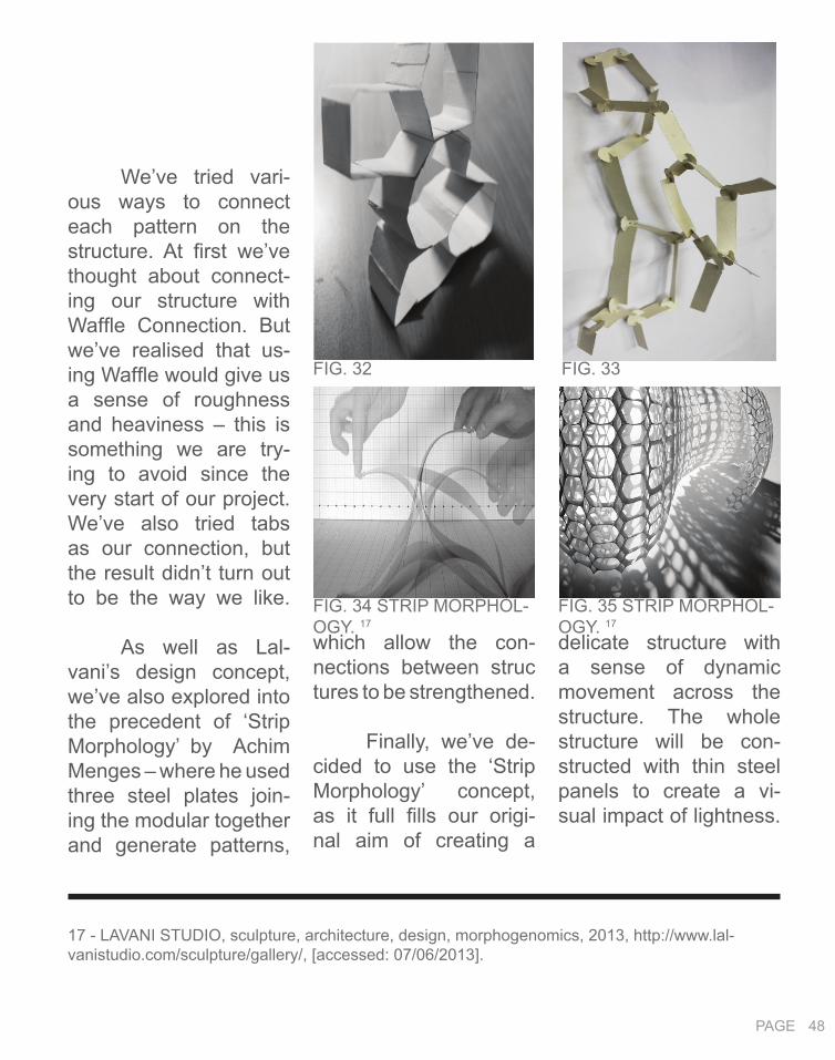
delicate structure with a sense of dynamic movement across the structure. The whole structure will be con-structed with thin steel panels to create a vi-sual impact of lightness.
which allow the con-nections between struc tures to be strengthened.
Finally, we’ve de-cided to use the ‘Strip Morphology’ concept, as it full fills our origi-nal aim of creating a
We’ve tried vari-ous ways to connect each pattern on the structure. At first we’ve thought about connect-ing our structure with Waffle Connection. But we’ve realised that us-ing Waffle would give us a sense of roughness and heaviness – this is something we are try-ing to avoid since the very start of our project. We’ve also tried tabs as our connection, but the result didn’t turn out to be the way we like.
As well as Lal-vani’s design concept, we’ve also explored into the precedent of ‘Strip Morphology’ by Achim Menges – where he used three steel plates join-ing the modular together and generate patterns,
FIG. 32 FIG. 33
FIG. 34 STRIP MORPHOL-OGY. 17
17 - LAVANI STUDIO, sculpture, architecture, design, morphogenomics, 2013, http://www.lal-vanistudio.com/sculpture/gallery/, [accessed: 07/06/2013].
FIG. 35 STRIP MORPHOL-OGY. 17

PAGE 48 PAGE 49
FIG. 36
FIG. 37
FIG. 38 FIG. 39

PAGE 50
els by hand to adjust the angles. This allow us to create an elegant and a sense of freedom for our overall structure.
but more tests will need to be conducted.
For us to achieve a perfect and smooth edge, we cut it through laser cutting method. The Voronoi cell pat-terns were lightly etched, so we can fold the pan-
After develop-ing the prototype of our model, we come to re-alisation the difference between an ideal design idea and the reality. We will need to consider various factors such as the capacity our pro-totype material can be bent. We tried two ma-terials for our prototype, one is polypropylene sheet and the other is ivory card. Both of them did not turn out to be the curvature we’ve ex-pected. The polypropyl-ene is too hard to bend, while the ivory card is too soft. In this case, we need to reconsider the overall structure again, possibly to extend the length of the design;
FIG. 40

PAGE 50 PAGE 51
B.6. TECHNIQUE PROPOSAL We are consider-
ing using the Welding joints as our connec-tions. We’ve looked into the 2008 Beijing Olym-pic Stadium as one of our precedents. The steel structures form rigid connections and at the same time would al-low our overall structure to curve accordingly.
FIG. 42 BEIJING OLYMPIC STADIUM. 18
FIG. 41 WELDING STRUCTURE - BEIJING OLYMPIC STA-DIUM. 18
18 - CHINA SUSPENDS WORK ON OLYMPIC ‘BIRD NEST’, 2004, http://wirednewyork.com/forum/showthread.php?t=3756&page=2, [accessed: 07/06/2013].

B.7. A L G O R I T H -MIC SKETCHES
PAGE 52

PAGE 52 PAGE 53
3D patterning - Line attract and repel.
Imitating external force using Kangaroo.

PAGE 54
B.8. LEARNING OBJEC-TIVES AND OUTCOMES

PAGE 54 PAGE 55
an elegant form and high rigidity in joints.
F e e d b a c k : It is suggested that we need to think more into the realisa-tion of our project, such as a detailed connection drawing or prototype can be produced. We would need to do more research on the connec-tions for our structure for our further development.
change the structure, it is interesting to imi-tate the natural force on Kangaroo. The Vor-onoi geometry we used for our final patterning, we started with set ting up grid points, which ir-regular patterns are formed. Even though the grid points are asym-metrical, we can still find the center point for our patterns and they are arranged in a row.
Without the theo-retical research, we wouldn’t come up with the idea of ‘Strip Mor-phology’ connection for our structure and know-ing how to use compu-tational design, which full fills our intention of
In conclusion, our group managed to gen-erate a structure that act as a medium be-tween the urban and rural environment, also at the same time cre-ating an eye catching effect to highlight the Wyndham Freeway.
In this case, the theoretical research af-fected our knowledge of architecture very well. For our precedent, the research helped us to adopt Lavalni’s design concept to generate a structure using natural force and apply tension to the surface; although this did not succeed as patterns tend to be stretched when we

PAGE 56
PART C. PROJ-ECT PROPOSAL`
PAGE 56 PAGE 57
C.1. GATEWAY PROJECT: DESIGN CONCEPT
Feedback from the critic juries sug-gested that a stronger design concept would be required to make our project more convinc-ing. For us to strength-en our proposal, it is necessary to change our design concept.
As a result we’ve taken one step further into the development of our project. We changed our original design ap-proach for our project to be more persuasive to sit on the site. We used the analogy of wind tur-bulence as our new de-sign approach; which is represented by the flipping opening pan-els across the structure.
Having the anal-ogy of wind turbulence as our starting point; which solidifies our con-

PAGE 58
highlights the difference between the two contexts.
We’ve also in-crease the length of our overall structure as to overcome the deformation of curva-ture for our final model.
fast speed movement of city life. However, on the other side of the project – exiting the city is designed with a curved edge to demon-strate a slower motion in the rural and natu-ral environment. The asymmetrical structure
cept and taking us to the next stage of devel-opment. We inserted the formula of the wind turbulence in Grass-hopper for us to gener-ate the opening angles for our flipping panels.
The methods and efficiency in terms of construction were also important to consider during the develop-ment. We generated panels with uniformed angles of openings across our structure. Even the angles are the same; they can still be observed by the visi-tors with different lights and shades experienc-es and understandings.
If viewed from the top, one side of our project – going towards the city, is designed to form a relatively straight edge, to emphasise the
FIG. 43
FIG. 44
FIG. 43
FIG. 45

PAGE 58 PAGE 59
19 - Wyndham City Council, Gateway Competition Document, Western Gateway Design Project, 2011, LMS, http://app.lms.unimelb.edu.au/webapps/portal/frameset.jsp?tab_tab_group_id=_5_1&url=%2Fwebapps%2Fblackboard%2Fexecute%2Flauncher%3Ftype%3DCourse%26id%3D_262336, [ACCESSED: 07/06/2013].
SITE ANALYSIS
develop multiple experi-ences and best viewing result for the drivers ei-ther going or leaving the
three roads of the Wyn-dham Freeway – on Site A. We want our project act as a streetscape and
The project is act-ing as a median between Melbourne city and Wyndham city over the distance of the freeway. By any means, it should always be an eye-catch-ing structure and ap-preciated by everyone.
After analysing the direction of traffic along the freeways, we locat-ed our project along the
M E L B O U R N E
W Y N D H A M
FIG. 43
FIG. 45
FIG. 46 WYNDHAM SITE. 19

PAGE 60
City. Our project is 80 metres long and 10 me-tres in height, with such scale, we are aiming to create strong visual im-pact and allow the drivers to capture this installa-tion with a fast speed as well as from a distance.
Our project will be constructed with steel to provide an elegance and eye-catching effect on site. In order for us to avoid bulky feelings and at the same time have enough strength to support the whole structure; we designed our main structures to be constructed with 250 x 190 hollow rectangu-lar steel columns and steel panels as our flip-ping panels. The reflec-tive characteristic of the material would defi-nitely become the high-light point of the site.
THE SITE
SITE A - CHOSEN LOCATION FOR THE INSTALLATION
DIRECTION OF TRAFFIC ALONG THE FREEWAYS

PAGE 61
A S S E M B LY ON SITE
Most of our mate-rial will be prefabricated, not only because most of our structure elements are unique in shape but also to save labour, cost and time. Before all the structure elements to be assembled, they will be arranged and cut into the right scale before being transported onto the site.
The materials can be transported onto the site with trucks and we can access the site us-ing the freeway with-out affecting the traffic.

PAGE 62
1. In order for us to assemble the main structure together, we will need to construct the footings first; which will be reinforced concrete embedded underground.
2. The bottom hol-low rectangular column structure will be as-sembled in place first by connecting the foot-ings with bolts and steel plates. Then we will construct the structure from bottom to the top.
3. The panels are placed last over the struc-ture; connected using bolts and metal plates.
4. For the purpose of avoid rusting; we would apply a layer of zinc paint-ing as a finishing layer.
STEP ONE
STEP TWO
STEP THREE

PAGE 62 PAGE 63
C.2. GATEWAY PROJECT: TECTONIC ELEMENTS
For our project, we are mainly focusing on creating a sense of el-egance, in term of both material and structures; but at the same time the materials are required to be flexible to bend ac-cording to the curvature of our structure. In this case we’ve decided to use steel as our mate-rial, not only it can be deflected into the cur-vature we wanted and can undertake strong compression force, but also because the shiny and reflective material texture suits our origi-nal aim of creating an eye-catching structure.

other parts of the project. The foundation would be constructed with re-inforce concrete which will be embedded under-ground; and metal plate will be connected with the concrete for the hol-low rectangular column structure to be bolted.
We adopted Shigeru Ban’s Paper Tower connection meth-ods for our final founda-tion connecting meth-ods.20 The entire load from the structure will be transferred onto the foundation, so it would require a more rigid con-nection compare to the
PAGE 64
F O U N D AT I O N S T R U C T U R E
P R O T O T Y P E S
We’ve tested sev-eral connection methods that can be used for our structural connections.
FIG. 47 SHIGERU BAN’S PAPER TOWER. 20
20 - DESIGNBOOM, architect, design, art, technology, SHIGERU BAN: PAPER TOWER, 2012, http://www.designboom.com/architecture/shigeru-ban-paper-tower/, [accessed: 07/06/2013].

PAGE 65
S T R U C T U R E C ON N E C TIONF I R S T
We then developed a few prototypes for our structure connections. First we’ve come up with an idea of bolting the three columns around a circle metal plate.
A N A L Y S I S : Soon, we’ve came to realisation that this type of connection is too weak in term of rigidity. The connection between the column and steel plate are too flexible which will be easily bent.

PAGE 66
S T R U C T U R E C ON N E C TIONS E C O N D
Then for our sec-ond prototype, we had an idea of having two metal plates with curved edge compressing the three columns which are closely positioned together with bolts.
A N A L Y S I S : This type of con-nection is strong in term of rigidity, but considering about the economic use of material and efficient nesting – this would not be preferred; and most importantly this type of connection wouldn’t al-low our overall structure to be curved accordingly.

PAGE 66 PAGE 67
S T R U C T U R E C ON N E C TIONT H I R D
For our third pro-totype, we’ve tried fin-ger joints as our con-necting methods. The result turned out very neat, stable and elegant.
A N A L Y S I S : However our group are not satisfied with this type of joint, as we think the finger joints are too simple for our proj-ect connection. So our group decided to look for more possibilities.

PAGE 68
S T R U C T U R E C ON N E C TIONF O R T H
We adopted the concept from 2008 Bei-jing Olympic Stadium and developed a welded structure as one of our prototype. This type of connection has a high strength to support the structure, as well as ef-ficiency in construction.
A N A L Y S I S : Nevertheless, it is expensive to be built and the change form of steel during extreme climate would also be a problem, as there are no gapes in between the joints for the material to either expand or shrink.

PAGE 68 PAGE 69
S T R U C T U R E C ON N E C TIONF I N A L

PAGE 70
Finally we’ve de-veloped a connection adopting the concept of Strip Morphology as our final structure connec-tion. The bending metal strips connecting the three columns together is undertaking a compres-sion force which creating enough strength to sup-port the whole structure.
A N A L Y S I S : This type of con-nection uses less mate-rial compare to the two prototypes we devel-oped before and most importantly the strip met-al connection provide a sense of elegance.
FINAL CONNECTION

PAGE 71
C.3. GATE WAY PROJ-ECT: FINAL MODEL

PAGE 72

PAGE 72 PAGE 73

PAGE 74
A
C D
B
A B
C D

PAGE 74 PAGE 75
C is the south el-evation of the design. It can be experienced while driving passes the project towards the city. Visitors would be able to experience the light and shadows cre-ated by the openings.
D is the west eleva-tion of the project; it can be viewed by the drivers who are exiting the city.
A is the North el-evation of the project. This can be viewed while driving towards the city from a distance or drive pass while exit-ing the city. The fluidity of the surface curvature creates a continuous dy-namic flowing effect for the visitors at the same time the visitors would be able to experience light and shadows cre-ated by the openings.
B is the east el-evation. This can be viewed while people driving towards the city, the flipping panels can be captured by the visi-tors easily and create a sense of elegance.

PAGE 76
C.4. ALGORITHMIC EX-P L O R A T I O N S

PAGE 77
I made the panels on my structure open on the angle I wanted. It took a while for me to work out how to do so, as it wasn’t working be-fore because I didn’t re-alise the ‘item’ that I se-lected were curved lines. As a result I need to add the ‘line’ component as a mediator between the curved line and rotation component for the pan-els to rotate accordingly.

PAGE 78
C.5. LEARNING OBJEC-TIVES AND OUTCOMES
Overall, we’ve achieved an eye – catching design project for the Wyndham Gate-way Project. In term of our final proposal, sense of elegance success-fully acts as our focus-ing point, it act as an important mediates and enables complexity. We believe our project can create a shared experi-ence for the visitors, also strengthen the image of community by turning our project into Wyn-dham city land mark.
The weekly read-ings and each week’s journal allow me to gain a better understand-ing as well as put more thoughts into the ben-efits of using compu-tation and parametric designs during design

PAGE 78 PAGE 79
21 - Richard Williams, ‘Architecture and Visual Culture’, in Exploring Visual Culture : Definitions, Concepts, Contexts, ed. by Matthew Rampley (Edinburgh: Edinburgh University Press, 2005), pp. 102 - 116.
or travel within them.
As we design our project we studied much different architec-ture as our precedent. These really provide me knowledge on the differ-ent concepts that each architecture is applying as well as their ways to apply computation and parametric designs into their projects. Although we did not success in reconstruct the prece-dent we followed at the very start – which is Haresh Lavani’s work, we managed to adopt his design concept and applied it in a differ-ent way to our project.
By designing the project, it expands my knowledge of both com-putational technique and
capacity and curvature of the overall form etc..
Computational de-sign shortens the dis-tance between the archi-tects’ ideal design and the reality; also allow the architects to control and change his design easily without affect-ing the original concept.
Some people think architecture is just a shelter; a place where we perform daily basis. Others believe archi-tecture is considered as ‘the most public of the arts.21 I would agree with the latter. Architec-tures should be viewed and appreciated as streetscapes around the corner which provide a nice experience as the visitors move around
process. Both the read-ings and actually de-signing a project using the soft-wares changed my view on computation and parametric designs.
Even at the start of this project I didn’t really enjoy design projects us-ing computers; but after I started to learn more about how to use the software, I can see the advantage of the com-putation and parametric design methods straight away. It’s efficiency – less time are needed compare to hand sketch drawings; it’s reliable – less error will be made during the process; and most importantly it as-sist the designer to pro-duce a design that is realistic, such as cal-culate the load bearing

tain angle. We’ve tried explode the surface and making a list of the items then connect the ‘Rotate Axis’ component to the ‘Item’. However it did not work. Then we’ve come to realisation that as our surface is on a curva-ture, so when we link the ‘Item’ and ‘rotate axis’ together, the rotation is based on a curved line. Knowing this, we add-ed the component ‘line’ in between the ‘item’ and ‘rotate axis’ to cre-ate a straight base for the rotation to work.
However, we’ve overcome all the dif-ficulties for producing this elegant and eye-catching project. Our group enjoyed working together, learning from
real world construction. We had problem with the bending capacity of our prototype materials. We’ve used two material, polypropylene and ivo-ry card to construct our prototype, both of them did not achieve the cur-vature we expected. So we reconsidered about our overall form. As a result, we’ve increased our overall structure in length for us to achieve a smooth curvature for our final model. By increas-ing the length it also al-lows a longer period of time for the visitors to experience our project.
When we were designing our flipping panels we had trouble to manage the panels to be opened on a cer-
architecture, especially in term of patterning and has greater opportunities to look for more possi-bilities. At the same time the computation design can provide us some unexpected outcomes. The designing process provide me with the idea of complex designs can be achieved via com-putation by using simu-lating, prototype testing and parameters to con-trol the design efficiently.
We’ve encoun-tered a few problems while designing our proj-ect using technologies.
The prototype process in Part B made us to realise the differ-ence between an ideal designed structure and
PAGE 80

PAGE 81
each other and develop-ing new ideas. My skill in using soft-wares such as Grasshopper and Kangaroo plugins, Rhi-no, Indesign and Pho-toshops has improved a lot after this semester. This subject also intro-duced me to the idea of digital publishing web-site – Issuu; it is such a handy tool for me to know and I will be cer-tainly applying the skills I’ve learnt this semes-ter in my future study.

R E F E R E N C E S : • Burry, Mark (2011). Scripting Cultures: Architectur-al Design and Programming (Chickester: Wiley), pp. 8-71
• CHETAN,DAVINCIROTATINGTOWERINDUBAI,http://techand-facts.com/da-vinci-rotating-tower-dubai/, [accessed: 5/6/2013]
• CHINA SUSPENDS WORK ON OLYMPIC ‘BIRDNEST’, 2004, http://wirednewyork.com/forum/showthread.php?t=3756&page=2, [accessed: 07/06/2013].
• Designboom: Arhitecutre design art technology, Sou-maya Museum by Fernando Romero architects, 2012, http://www.designboom.com/archi tecture /soumaya-museum-by-fernando-romero-architects/, [accessed: 07/06/2013].
• Designboom–architecturedesignarttechnology,ZahaHadid:GalaxySohoCompleted,2012,http://www.designboom.com/archi-tecture/zaha-hadid-galaxy-soho-completed/,[accessed:07/06/2013].
• FUTURISTIC NEWS, Museo Soumaya, 2013,Mexico City, http://futuristicnews.com/museo-soumaya-mexico-city/, [accessed 07/06/2013].
• LAVANI STUDIO, sculpture, architecture, de-sign, morphogenomics, 2013, http://www.lalvanistu-dio.com/sculpture/gallery/, [accessed: 07/06/2013].
• RichardWilliams,‘ArchitectureandVisualCulture’,inExplor-ingVisualCulture:Definitions,Concepts,Contexts,ed.byMatthewRampley(Edinburgh:EdinburghUniversityPress,2005),pp.102-116.
• WALTDISNEYCONCERHALL,LOSANGELES,CA,USA,2011,<http://www.strangebuildings.thegrumpyoldlimey.com/2011/08/walt-disney-concert-hall-losangeles-ca.html>, [accessed 5/6/2013]
• Woodbury, Robert (2010). Elements of Para-metric Design (London: Routledge) pp. 7-48
• Wyndham City Council, Gateway Competition Document,Western Gateway Design Project, 2011, LMS, http://app.lms.un-imelb.edu.au/webapps/portal/frameset.jsp?tab_tab_group_id=_5_1&url=%2Fwebapps%2Fblackboard%2Fexecute%2Flauncher%3Ftype%3DCourse%26id%3D_262336, [ACCESSED: 07/06/2013].
• SJET, VOLTADOM, http://www.sjet.us/MIT_VOLTADOM.html, [accessed: 07/06/2013].• TEDXbROOKLYN – Haresh Lavani, 2011, http://www.youtube.com/watch?v=nir9fXCJX08, [accessed: 07/06/2013].
• Yehuda E.Kalya, Architecture’s New Media: Prin-ciples, Theories, and Methods of Computer – Aided De-sign (Cambridge, Mass. : MIT Press, 2004), pp5 – 25.
• Zaha Hadid Arhitects, Galaxy Soho, http://www.zaha-hadid.com/architecture/galaxy-soho/, [accessed: 07/06/2013].
• Zaha Hadid Architect, Nordpark Railway Sta-tions, http://www.zaha-hadid.com/architecture/nor-dpark-railway-stations/, [accessed: 07/06/2013].