fiber-optic design - jytech.com · fiber-optic design core for spectroscopic applications,...
TRANSCRIPT

Fiber-optic desigNCoreFor spectroscopic applications, generally, multi-mode step index silica fibers are used. These range in core thickness from 50 to 1000 microns. The core is made out of pure silica. Other fiber cores with much higher absorption are made out of cer-tain glass types or plastics. These are not offered in this catalog. First a distinction is made between silica with high or low OH content. Silica fibers with high OH (600-1000 PPM) are used in the UV/VIS wavelength range because of the low absorption in the UV. They are referred to as UV/VIS fibers. For Deep-UV applications (below 230 nm) special solar-
ization resistant fibers can be used. The water content causes strong absorption peaks in the NIR wavelength range. In order to get good fibers for the NIR range, the “water” is removed from the silica. This results in low OH fibers (<2 PPM) with low absorption in the NIR. They are referred to as VIS/NIR fibers.New in this catalog are the so-called broadband fibers, which can be used for the UV-NIR range (250-2500 nm), the product code for these fibers is UVIR.
Cladding In order to get the light guiding effect the core is cladded with a lower index of refrac-tion material. For the highest quality fibers with the lowest absorption this is a fluorine-doped silica, the so-called silica-silica or all-silica fibers with a numerical aperture (NA) of 0.22.
Buffers Without further protection fibers would easily break, because of small scratches or other irregularities on the surface. Therefore a next layer, the buffer, is added. This buffer also determines under what circumstances the fiber can be used. Temperature range, radiation, vacuum, chemical environment and bending are factors to be consid-ered. Polyimide buffers offer a wide temperature range (-100 to 400°C) and superior solvent resistance. Also, this material is non-flammable. Drawbacks are sensitivity to micro bending and the difficulty to remove it. For extreme temperatures (-270 to 700°C) metal buffers are used. Metal buffers can withstand a continuous high temperature up to 500 °C and intermittent even up to 700°C. Low outgas-sing makes them also excellent for use in UHV envi-ronments.
116 | [email protected] | www.avantes.com
Fiber O
ptics

Technical DataFiber Material Standard
Temperature Range -190 °C to +400°C
Fiber type Step index Mutimode
Core Numerical Aperture 0.22 ± 0.02
Buffer Polyimide
Available Diameters 50/100/200/400/600/800/1000 µm
Laser damage resistant core 1,3 kW/mm2 CW at 1060 nm, up to 10 J, pulsed
Bend radius momentary 100 x clad radius long term 600 x clad radius
Transmission UV/VIS fibers
Transmission VIS/NIR fibers
Transmission UV/VIS/NIR broadband
Typical Attenuation
0
0.2
0.4
0.6
0.8
1
1.2
1.4
1.6
1.8
2
200 300 400 500 600 700 800 900 1000 1100 1200 1300 1400 1500 1600 1700 1800
Wavelength (nm)
Atte
nuat
ion
(dB/
m)
0
5
10
15
20
25
30
35
40
45
50
Atte
nuat
ion
(dB/
km)
[email protected] | www.avantes.com | 117

118 | [email protected] | www.avantes.com
Most spectroscopic applications with fiber-optics have been restricted to wavelength ranges above 230 nm, because standard silica fibers with an undoped core and fluorine doped cladding are frequently damaged by exposure to deep-UV light (below 230 nm). This solarization effect is induced by the formation of “color centers” with an absorbance band of 214 nm. These color centers are formed when impurities (like Cl) exist in the core fiber material and form unbound electron pairs on the Si atom, which are affected by the deep-UV radiation.
Not long ago, solarization resistant fibers, which were hydrogen loaded, were devel-oped (UVI). The disadvantage of these fibers is the limitation on smaller fiber
diameters and limited lifetime, caused by the H2 outgassing from the fiber. Recently, with the availability of a modi-fied core preform, a new fiber became available (UVM). This fiber provides long-term stability at 30-40% transmission (for 215 nm).
All UV/VIS fiber-optic probes, cables and bundles with core diameters of 100 µm, 200 µm, 400 µm, 600 µm, 800 µm and 1000 µm can be delivered with solariza-tion resistant fibers. All assemblies, made by Avantes, are pre-solarized for an 8-hrs period, to have a constant transmission of 30-40% @ 215 nm.
Solarization Resistant Fibers for Deep-UV applications
Fiber O
ptics

[email protected] | www.avantes.com | 119
Ordering Information-SR • Solarization resistant fiber for DUV applications

120 | [email protected] | www.avantes.com
Ordering Information-ME • flexible chrome-plated brass outer jacket, with hooked profile
-BX • Heavy industrial stainless steel jacket, with fully interlocking profile
-MS • stainless steel spiral jacket with glassilk and gray outer silicon rubber coating
-FX • stainless steel jacket for rigid / fixated setups
Fiber-optic Jacketing
For different applications Avantes offers different jacketing material. Standard fiber-optic cables and bifurcated cables are protected by a Kevlar reinforced poly-propylene inner tubing with PVC red outer jacket. All of our standard reflection probes are protected by a flexible stainless steel jacket with interlocking profile (BX) or a chrome-plated brass outer jacket, with hooked profile (ME) for optimal strain relief with silicon or PTFE inner tubing. For waterproof and some medical applications stainless steel spiral jacketing with glas-
silk and gray outer silicon rubber coating can be provided. Inside this jacket silicon or PTFE inner tubing is used as well. For heavy industrial environments we advise the metal stainless steel (-BX) jacketing. It features a tensile strength of 950N. For special cases we can offer our form holding jacketing (FX). Some specifics on the jacketing can be found in the following technical information.
Contact us if you have any special conditions requirements.
Technical Data
Jacketing material Kevlar reinforced PVC
Chrome pla-ted brass (ME)
Stainless Steel (BX)
Silicon coated stainless steel (MS)
Stainless Steel (FX)
Inner Tubing Polypropylene Silicon/PTFE Silicon/PTFE Silicon/PTFE Steel/Copper
Outer dimensions 3.8 mm 5.0 mm 6.0 mm 5.8 mm 6.1 mm
Min. bending radius 18 mm 18 mm 35 mm 18 mm 35 mm
Temperature Range -20°C to +65°C -65°C to +250°C -65°C to +250°C
-60°C to +180°C -65°C to +250°C
Tensile Strength 150 N 350 N 950 N 70 N n.a.
Application Standard Industrial Heavy Industrial Waterproof IP67 Industrial
Standard
-MS
-ME
-BX
-FX
Fiber O
ptics

[email protected] | www.avantes.com | 121
All Avantes fiber-optic cables and probes can be modified to customers request. Most materials we use in our fiber-optic assemblies can be replaced with others to improve specific chemical or thermal resis-tance or to enhance vacuum or pressure properties. Please contact our fiber design engineers with your specific request.
In the following paragraphs some of the most essential technical parameters are listed for the materials we use.
Thermal resistanceThe thermal resistance of a fiber-optic assembly depends on some of the mate-rials used: 1. Fiber: the standard fiber design has a
polyimide buffer, covering a wide ther-mal range –190 to 400 °C. For higher temperatures metal clad coated (to 500°C) fibers are recommended.
2. Jacketing: the standard jacketing is PVC based and has a small tempera-ture range (-20°C to 65°C), for higher temperatures a flexible metal jacketing (-BX/ME) with silicone inner tubing (up to 250°C) or stainless steel tubing (not flexible, to 750°C) is recommended.
3. Probe ends: connectors and ferrules are standard made of metal and have a wide temperature range. For special plastics, like PVC, PEEK and Teflon a lim-ited temperature range is applicable.
4. Bonding epoxy: the standard epoxy used is a heat curing bonding epoxy with a temperature range of –60°C to 175°C. The curing temperature is standard 100 °C, for high temperature ranges (order code -HT), the curing temperature is 200°C. For the HTX (extreme high temperature) fibers and probes silver soldering is used, a pro-cess that can withstand temperatures up to 500°C.
Fiber-optic Probe properties
Ordering Information-HT • High Temperature version (up to 200°C)
-HTX • Extreme High Temperature version (up to 500°C)
Technical DataTemperature range Fiber Jacketing Probe end Bonding
–20°C to +65°C Standard Polyimide Standard PVC Standard metal/ PVC/PEEK
Standard Epoxy
-30°C to +100°C Standard PolyimideMetal (-BX/ME) or silicone (-MS)
Standard metal/ PEEK
Standard Epoxy
-60°C to +200°C (HT) Standard PolyimideMetal (-BX/ME) or silicone (-MS)
Standard metal/ PEEK
High temperature curing epoxy
-100°C to +500°C (HTX) Metal clad coated BX/ME-jacket or none Metal Silver soldering
All fibers are available with SMA,
ST and/or FC/PC connectors

122 | [email protected] | www.avantes.com
Technical DataChemical environment Fiber Jacketing Probe end Epoxy
Acids weakStandard Polyimide
±
-BX/ME -MS -PEEK -PVC
±+++
St. steel 316PEEKHastelloy® C276
-+++
+
Acids strongStandard Polyimide
-
-BX/ME-MS-PEEK-PVC
-±+±
St. steel 316PEEK Hastelloy® C276
-+++
±
Bases weakStandard Polyimide
±
-BX/ME-MS-PEEK-PVC
++++
St. steel 316PEEKHastelloy® C276
++++
+
Bases strongStandard Polyimide
-
-BX/ME-MS-PEEK-PVC
++++
St. steel 316PEEKHastelloy® C276
++++
+
Aromatic carbonsStandard Polyimide
+
-BX/ME-MS-PEEK-PVC
++++
St. steel 316PEEKHastelloy® C276
++++
+
AlcoholsStandard Polyimide
±
-BX/ME-MS-PEEK-PVC
+±++
St. steel 316PEEKHastelloy® C276
++++
+
Ketons/EthersStandard Polyimide
+
-BX/ME-MS-PEEK-PVC
+-+-
St. steel 316PEEKHastelloy® C276
+++±
±
+ = good resistance± = conditional resistant- = not resistant
Chemical resistanceThe chemical resistance of a fiber-optic assembly depends on some of the materi-als used: 1. Fiber, the standard fiber design has a
polyimide buffer, which normally will not be in contact with the sample; the quartz core provides good resistance against most solvents.
2. Jacketing, the standard jacketing is PVC based and has a relative good chemi-cal resistance. The –BX stainless steel and –ME chrome plated brass jacketing also have a good chemical resistance, but are not waterproof. The Silicone metal jacketing (-MS) is recommended for waterproof environment, biomedi-cal applications, etc. The PEEK and PTFE jacketing have the best chemical resis-tance.
3. Probe ends, connectors and ferrules are standard made of stainless steel (316) and are not very well suitable in cor-rosive environment. For most corrosive
environments PEEK or Hastelloy® C276 are recommended.
4. Bonding, the standard heat-curing two- component epoxy used is resistant to water, inorganic acids and salts, alkalis and many aggressive organic solvents and most petrochemical products, and an extended range of organic and inor-ganic environments.
The table below gives a summary for the chemical resistance for most materials used. It has been drawn up on the basis of relevant sources in accordance with the state of the art; no claim to completeness. The data constitutes recommendations only, for which no liability can be accepted.Please contact us if you have any doubt about the materials to use for your applica-tion.
Ordering Information-PK • PEEK Probe material replaces Stainless Steel
-HY • Hastelloy® C276 Probe material replaces Stainless Steel
Fiber O
ptics

[email protected] | www.avantes.com | 123
Ordering Information-ST • ST connector instead of standard SMA
-FC/PC • FC/PC connector instead of standard SMA
SMA connectorsWe supply all of our standard fiber-optic cables, bundles and probes with SMA-905 connectors that easily fit into our complete range of spectrometers, light sources and accessories.The SMA-905 connectors are screw-fitted and can be rotated over 360 degrees. The typical insertion loss for the connectors is 0.5 dB. The maximum filling diameter for bundles is 2.46 mm
FC/PC connectorsOptional FC/PC-connectors can be mount-ed to our fiber-optic products. The multi-mode FC/PC connectors have an extremely low insertion loss of < 0.2 dB. The FC/PC
connector cannot rotate, always mounts into the same fixed position and therefore has a high reproducibility.
ST connectorsOptional ST-connectors can be mounted to our fiber-optic products.ST-connectors easily mount with their bayonet type of fitting, and can therefore not rotate, i.e. they mount in a fixedposition. The maximum filling diameter is 1.5 mm, typical insertion loss is 0.3 dB.
Fiber-optic Connectors

124 | [email protected] | www.avantes.com
Avantes offers a wide range of fiber-optic cables, which can be made in a variety of lengths and configurations to meet your needs. For common applications, a 2 meter length is sufficient for this reason it is our standard fiber length.
Avantes offers SMA-905 or FC/PC connec-tors and these can be the same or different on both ends. For some applications, spe-cial round to linear fiber cables are recom-mended in which a bundle of fibers con-figured in a round pattern on one end and a linear array on the other end. The linear array (typically 1 mm in height) is aligned with the slit height of the spectrometer which is also 1 mm. This fiber configuration provides maximized light throughput for applications requiring high-sensitivity.
Fiber-optic cable types and diameters are recommended based upon the wavelength range being measured and the sensiti-vity required for a measurement. For the UV range high OH UV/VIS fiber is recom-mended. For customers working below 240 nm in the UV, special high OH UV/VIS fiber called solarization resistant fiber (SR)
is recommended. For longer wavelengths low OH VIS/NIR fiber is recommended. Best of both worlds can be achieved with our broadbandfiber. This gives you the com-bined performance of the UV and IR fibers. Avantes also offers a variety of jacketing options including Kevlar reinforced PVC sleeving with PTFE inner tubing (standard), chrome plated brass monocoil, stainless steel BX, silicone coated stainless steel monocoil and other special jacketings upon request. For applications requiring high tempera-ture resistance, special high temperature epoxy (HT) is available and should be speci-fied at the time of order.
Recommended wavelengths for different cables:- 180-800 nm: Solarization resistant (-SR)- 200-800 nm: UV/VIS (UV)- 350-2500 nm: VIS/NIR (IR)- 250-2500 nm: UV/VIS/NIR (UVIR)UV/IR available in core sizes 200, 400, 600 µm
Note: UVIR available in core sizes 200, 400 and 600 micron.
Ordering InformationFC-IR008-2 • Cable with 8 µm Fiber, 2 m length, SMA terminations
FC-xx050-2 • Cable with 50 µm Fiber, 2 m length, SMA terminations
FC-xx100-2 • Cable with 100 µm Fiber, 2 m length, SMA terminations
FC-xx200-2 • Cable with 200 µm Fiber, 2 m length, SMA terminations
FC-xx400-2 • Cable with 400 µm Fiber, 2 m length, SMA terminations
FC-xx600-2 • Cable with 600 µm Fiber, 2 m length, SMA terminations
FC-xx800-2* • Cable with 800 µm Fiber, 2 m length, SMA terminations
FC-xx1000-2* • Cable with 1000 µm Fiber, 2 m length, SMA terminations
FCB-xx050-2 • Bifurcated cable 2x50 µm, 2 m length, SMA terminations
FCB-xx100-2 • Bifurcated cable 2x100 µm, 2 m length, SMA terminations
FCB-xx200-2 • Bifurcated cable 2x200 µm, 2 m length, SMA terminations
FCB-xx400-2 • Bifurcated cable 2x400 µm, 2 m length, SMA terminations
FCB-xx600-2 • Bifurcated cable 2x600 µm, 2 m length, SMA terminations
Other lengths and fiber types are available. * 800-1000 µm with Acrylate buffer, black sleeving Specify xx = UV for UV/VIS fiber cables, IR for VIS/NIR and UVIR for broadband UV/VIS/NIR
Fiber-optic Cables
FCB-UVIR400-2
Fiber O
ptics
FC4-UVIR200-2-ME

[email protected] | www.avantes.com | 125
Multi-furcated Fiber-optic Cables
Simultaneous multi-point measurements and Avantes multi-channel spectro-meters, require multi-furcated fiber-optic cables. These assemblies can function as a combiner or splitter of light as they have multiple legs on side which converge into a single connector on the opposite side. Avantes offers virtually any combination possible, which can be adapted to your requirements.
Typical setups that require multi-furcated cables are:• One sampling point such as an integrat-
ing sphere, cosine corrector or collimat-ing lens being measured with several spectrometers (individual AvaSpecs or Multi-channel).
• Multiple illumination fibers splitting out from one light source to different sam-pling points.
All types of connectors, jacketings and fiber sizes are available for these multi-furcated fiber cables. Contact us to configure and quote you on your specific needs.
Ordering Information
FC4-xx200-2• Four-furcated cable, 4x200 µm fibers , all legs SMA terminated, total 2 m long, splitting
point in the middle
FC4-xx400-2 • As FC4-xx200-2, but with 4x400 µm fibers
FC4-xx600-2 • As FC4-xx200-2, but with 4x600 µm fibers
FC5-xx200-2• Five-furcated cable, 5x200 µm fibers, all legs SMA terminated, total 2 m long, splitting
point in the middle
FC5-xx400-2 • As FC5-xx200-2, but with 5x400 µm fibers
FC6-xx200-2• Six-furcated cable, 6x200 µm fibers, all legs SMA terminated, total 2 m long, splitting
point in the middle
FC6-xx400-2 • As FC6-xx200-2, but with 6x400 µm fibers
FC8-xx200-2• Eight-furcated cable, 8x200 µm fibers , all legs SMA terminated, total 2 m long, splitting
point in the middle
FC8-xx400-2 • As FC8-xx200-2, but with 8x400 µm fibers
Other lengths available on requestSpecify xx = UV for UV/VIS fiber cables, IR for VIS/NIR and UVIR for broadband UV/VIS/NIR
FC4-UVIR200-2-ME

126 | [email protected] | www.avantes.com
To obtain spectral information of the diffuse, or specular materials, reflection probes are used. The light from a light source is sent through six illumination fibers to the sample and the reflection is measured by a 7th fiber in the center of the reflection probe tip. The 7th fiber is coupled to a spectrometer configured to the appropriate wavelength range of inter-est. More illumination fibers can be added to get more energy from the light source and therefore increase the reflection signal level.
For measurements under an angle of 90°, the FCR-90-Option was developed. It’s a special adapter with a mirror positioned at 45° and can be easily mounted on the tip of Avantes standard reflection probes.
The FCR-COL is an adjustable UV/VIS/NIR collimating and focusing lens which enables focusing the measurement spot at an extended distance.
Technical Data
Fibers 7 fibers 200 mm or 400 mm core, 6 light-fibers, 1 read fiber, N.A.= 0.22. Standard 2 m length, splitting point in the middle.
Wavelength range 200-800 nm (UV/VIS), 350-2500 nm (VIS/NIR) or 250-2500 nm (UV/VIS/NIR)
Connectors SMA-905 connectors (2x)
Probe end Stainless steel 316 cylinder, 50 mm long x 6.35 mm diameter. Optionally –PK for PEEK or –HY for Hastelloy® C276
Jacketing The optical fibers are protected by a silicon inner tube and a flexible stainless steel (BX, O.D. 6.0 mm) or chrome plated brass (ME, O.D. 5.0 mm) outer jacket. The jacketing also gives stress relieve.
Temperature -30°C to 100°C. (-HT version 200 °C, -HTX version 500 °C)
Pressure Probe head 50 bar @ 25 °C
Bending Minimum bend radius: Short term (few seconds) 20-40 mm, long term: 120 -240 mm
Ordering InformationFCR-7xx200-2-BX/ME* • Reflection probe, 7 x 200 µm fibers, 2 m length, SMA term.
FCR-7xx400-2-BX/ME* • Reflection probe, 7 x 400 µm fibers, 2 m length, SMA term.
FCR-90-Option • 90° Reflection add-on reflector for use with all ¼” reflection probes
FCR-COL • Adjustable UV/VIS/NIR Collimating/focusing lens for FCR probes
Reflection Probes (Standard)
Options-HT • High Temperature version (up to 200°C)
-HTX • Extreme High Temperature version (up to 500°C)
-PK • PEEK Probe material replaces Stainless Steel
-HY • Hastelloy® C276 Probe material replaces Stainless Steel
* please specify jacket material
Specify xx = UV for UV/VIS fiber cables, IR for VIR/NIR and UVIR for broadband UV/VIS/NIR
Fiber O
ptics

[email protected] | www.avantes.com | 127
Ordering Information
FCR-19UV200-2-BX/ME* • Reflection probe UV/VIS, 17 x 200 µm UV/VIS illumination fibers, 2 read UV/VIS fibers in
separate legs, 2 m length, 3 SMA term.
FCR-19IR200-2-BX/ME* • As FCR-19UV200-2-BX/ME, but for VIS/NIR
FCR-19UVIR200-2-BX/ME* • Reflection probe UV/VIS/NIR, 17 x 200 µm UV/VIS/NIR illumination fibers, 2 read UV/
VIS/NIR fibers in separate legs, 2 m length, 3 SMA term.
FCR-90-Option • 90° Reflection add-on reflector for use with all ¼” reflection probes
FCR-COL • Adjustable UV/VIS/NIR Collimating/focusing lens FCR probes
* please specify jacket material
Reflection Probes with multiple legs
For some measurements, a reflection probe is needed that can be coupled to two spectrometers and a light source. A good example is a reflection measurement in the UV/VIS and NIR range. For these situa-tions, Avantes offers our reflection probes with multiple legs.
The light from a light source is coupled into a fiber bundle, consisting out of 17 illumination fibers which transport the
light to the end of the probe. The reflected light is uniformly reflected into the two read fibers, each of which is connected to a spectrometer. In the example of a UV/VIS and NIR configuration a mix of high OH UV/VIS fiber and low OH VIS/NIR fibers are used for the respective light wavelengths and spectrometer types.
For measurements under a 90° angle, the FCR-90-Option has been developed. It is an
adapter with a mirror mounted at 45° and can be easily mounted to the tip of these reflection probes.
To accurately focus a small measurement spot from a higher distance, the FCR-COL adjustable US/VIS/NIR collimating/focus-ing lens is available and can be mounted to the tip of these probes.
Technical Data
Fibers 19 fibers 200 µm core, 17 light-fibers, 2 read fibers in 2 separate legs, N.A.= 0.22. Standard 2 m length, splitting point in the middle.
Wavelength range 200-800 nm (UV/VIS), 350-2500 nm (VIS/NIR) or 250-2500 nm (UV/VIS/NIR)
Connectors SMA-905 connectors (3x)
Probe end Stainless steel 316 cylinder, 50 mm long x 6.35 mm diameter. Optionally –PK for PEEK or –HY for Hastelloy® C276
Jacketing The optical fibers are protected by a silicon inner tube and a flexible stainless steel (BX, O.D. 6.0 mm) or chrome plated brass (ME, 5.0 mm) outer jacket. The jacketing also gives stress relieve.
Temperature -30°C to 100°C. (-HT version 200°C, -HTX version 500°C)
Pressure Probe head 50 bar @ 25°C
Bending Minimum bend radius: Short term (few seconds) 20 mm, long term: 120 mm
Options-HT • High Temperature version (up to 200°C)
-HTX • Extreme High Temperature version (up to 500°C)
-PK • PEEK probe material replaces Stainless Steel
-HY • Hastelloy® C276 Probe material replaces Stainless Steel

128 | [email protected] | www.avantes.com
Ordering InformationFCR-14xx200-2-REF-BX/ME* • Reflection probe with reference, 14 x 200 µm fibers, 2 m length, SMA term.
Specify xx = UV for UV/VIS fiber cables, IR for VIR/NIR and UVIR for broadband UV/VIS/NIR* please specify jacket material
Reflection Probes with Reference
In order to correct fluctuations and drift from your light source, periodic referenc-ing is required. To facilitate this, Avantes offers this series of reflection probes with a self-referencing feature. The light com-ing from the light source is bundled into 12 fibers, which are split into two 6 fiber bundles. One of these bundles is carried to the probe end for sample measurements and the other bundle of 6 are directed to a white reflection tile built into the probe
to provide a light source reference. This reference leg is connected to a slave spec-trometer channel dedicated to light source referencing or may be routed to a single channel via a fiber-optic (contact a Sales Engineer about this special configuration). On the measurement side the probe end has a 7th fiber which reflects light back to the master spectrometer channel.
Technical Data
Fibers 14 fibers 200 µm core, 12 light-fibers, 2 x 1 read fiber, N.A.= 0.22. Standard 2 m length, splitting point in the middle.
Wavelength range 200-800 nm (UV/VIS), 350-2500 nm (VIS/NIR) or 250-2500 nm (UV/VIS/NIR)
Connectors SMA-905 connectors (3x)
Probe end Stainless steel 316 cylinder, 50 mm long x 6.35 mm diameter . Optionally –PK for PEEK or –HY for Hastelloy® C276.
Jacketing The optical fibers are protected by a silicon inner tube and a flexible stainless steel (BX, O.D. 6.0 mm) or chrome plated brass (ME, 5.0 mm) outer jacket. The jacketing also gives stress relieve.
Temperature -30°C to 100°C. (-HT version 200°C, -HTX version 500°C)
Pressure Probe head 50 bar @ 25°C
Bending Minimum bend radius: Short term (few seconds) 20 mm, long term: 120 mm
Options-HT • High Temperature version (up to 200°C)
-HTX • Extreme High Temperature version (up to 500°C)
-PK • PEEK Probe material replaces Stainless Steel
-HY • Hastelloy® C276 Probe material replaces Stainless Steel
Fiber O
ptics

[email protected] | www.avantes.com | 129
For some medical and semiconductor applications, a (very) small tip is desired to do reflectance measurements. Avantes offers two standard diameters of small tip reflection probes, 1.5 and 2.5 mm and each tip is normally 100 mm long (custom lengths available).
The probe is configured with an illumina-tion leg with six 200 µm fiber cables which connects to a fiber coupled light source and a single 200 µm read fiber cable to
measure the reflection via connection to a spectrometer.
A special angled fiber holder (AFH-15) is available for the 1.5 mm diameter reflec-tion probe. This device enables reflection measurements under angles of 15, 30, 45, 60, 75 and 90 degrees. For more informa-tion, see ‘reflection probe holders’ at the end of this fiber-optics chapter.
Reflection Probes with Small Tips
Ordering InformationFCR-7UV200-2-1.5x100 • Reflection probe, 1.5 mm tip, UV/VIS, 7 x 200 µm fibers, 100 mm long, 2 m length, SMA
FCR-7IR200-2-1.5x100 • As FCR-7UV200-2-1.5x100, but with VIS/NIR fibers
FCR-7UVIR200-2-1.5x100 • As FCR-7UV200-2-1.5x100, but with UV/VIS/NIR fibers
FCR-7UV200-2-2.5x100 • Reflection probe, 2.5 mm tip, UV/VIS, 7 x 200 µm fibers, 100 mm long, 2 m length, SMA
FCR-7IR200-2-2.5x100 • As FCR-7UV200-2-2.5x100, but with VIS/NIR fibers
FCR-7UVIR200-2-2.5x100 • As FCR-7UV200-2-2.5x100, but with UV/VIS/NIR fibers
Technical Data
Fibers 7 fibers 200 µm core, 6 light-fibers, 1 read fiber, N.A.= 0,22. Standard 2 m length, splitting point in the middle.
Wavelength range 200-800 nm (UV/VIS), 350-2500 nm (VIS/NIR) or 250-2500 nm (UV/VIS/NIR)
Connectors SMA-905 connectors (2x)
Probe end Stainless steel cylinder, 100 mm long x 1.5 or 2.5 mm diameter.
JacketingThe optical fibers are protected by a Kevlar reinforced PTFE jacket with PVC sleeving. OD: 3.8 mm
Temperature -20°C to 65°C
Bending Minimum bend radius: Short term (few seconds) 20 mm, long term: 120 mm
For diffuse or specular reflection measurements, take a look at the RPH-1
reflection probe holder
130 | [email protected] | www.avantes.com
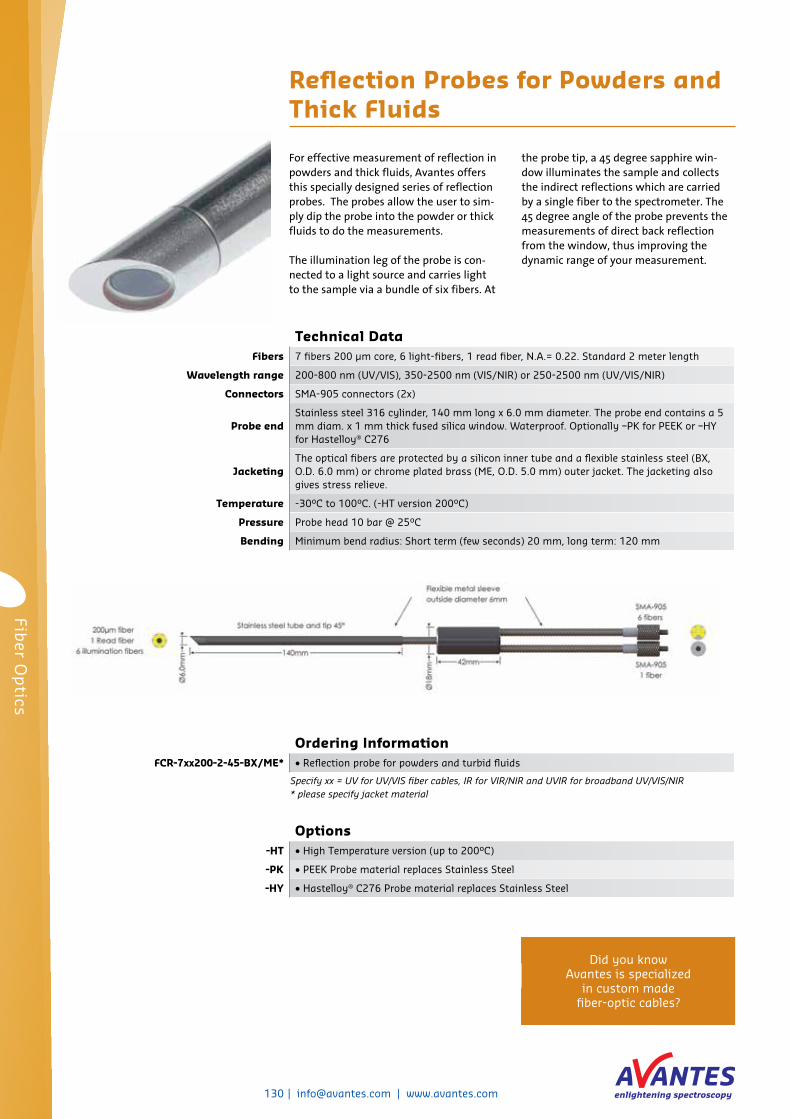
For effective measurement of reflection in powders and thick fluids, Avantes offers this specially designed series of reflection probes. The probes allow the user to sim-ply dip the probe into the powder or thick fluids to do the measurements.
The illumination leg of the probe is con-nected to a light source and carries light to the sample via a bundle of six fibers. At
the probe tip, a 45 degree sapphire win-dow illuminates the sample and collects the indirect reflections which are carried by a single fiber to the spectrometer. The 45 degree angle of the probe prevents the measurements of direct back reflection from the window, thus improving the dynamic range of your measurement.
Reflection Probes for Powders and Thick Fluids
Options-HT • High Temperature version (up to 200°C)
-PK • PEEK Probe material replaces Stainless Steel
-HY • Hastelloy® C276 Probe material replaces Stainless Steel
Technical DataFibers 7 fibers 200 µm core, 6 light-fibers, 1 read fiber, N.A.= 0.22. Standard 2 meter length
Wavelength range 200-800 nm (UV/VIS), 350-2500 nm (VIS/NIR) or 250-2500 nm (UV/VIS/NIR)
Connectors SMA-905 connectors (2x)
Probe end Stainless steel 316 cylinder, 140 mm long x 6.0 mm diameter. The probe end contains a 5 mm diam. x 1 mm thick fused silica window. Waterproof. Optionally –PK for PEEK or –HY for Hastelloy® C276
Jacketing The optical fibers are protected by a silicon inner tube and a flexible stainless steel (BX, O.D. 6.0 mm) or chrome plated brass (ME, O.D. 5.0 mm) outer jacket. The jacketing also gives stress relieve.
Temperature -30°C to 100°C. (-HT version 200°C)
Pressure Probe head 10 bar @ 25°C
Bending Minimum bend radius: Short term (few seconds) 20 mm, long term: 120 mm
Ordering InformationFCR-7xx200-2-45-BX/ME* • Reflection probe for powders and turbid fluids
Specify xx = UV for UV/VIS fiber cables, IR for VIR/NIR and UVIR for broadband UV/VIS/NIR* please specify jacket material
Did you know Avantes is specialized
in custom made fiber-optic cables?
Fiber O
ptics

[email protected] | www.avantes.com | 131
Ordering InformationFCR-7xx200-2-45-IND • 1/2” Reflection probe for powders and turbid fluids
FCR-TIP45 • 1/2” Replacement tip with sapphire window for UV/VIS/NIR
Specify xx = UV for UV/VIS fiber cables, IR for VIR/NIR and UVIR for broadband UV/VIS/NIR
For industrial applications that need reflec-tion measured in thick liquids or powders, this probe is the ideal choice. The stain-less steel cylinder and probe end make it withstand extreme situations. The tip is exchangeable and waterproof. Optionally PEEK or Hastelloy® C276 can be used as tip material.
The light enters from the light source through six bundled fibers to the probe end, where it lights the material to be ana-lyzed through a silica window angled at 45 degrees. This angle prevents any light to be reflected from the window. The light is selectively reflected through the seventh fiber in de probe. This fiber leads to the connected spectrometer.
1/2” Industrial Reflection Probes for Powders and Thick Fluids
Technical DataFibers 7 fibers 200 µm core, 6 light-fibers, 1 read fiber, N.A.= 0.22, standard 2 meter length
Wavelength Range 200-800 nm (UV/VIS), 350-2500 nm (VIS/NIR) or 250-2500 nm (UV/VIS/NIR)
Connectors SMA-905 connectors (2x)
Probe End Stainless steel cylinder, 120 mm long x 12.7 mm (1/2”) diameter. The probe end contains a ca. 10 mm diam. x 1 mm thick sapphire window. The probe tip is exchangeable and waterproof. Optionally –PK for PEEK or –HY for Hastelloy® C276
JacketingThe optical fibers are protected by a silicon inner tube and a flexible stainless steel (BX, O.D. 6.0 mm) or chrome plated brass (ME, 5.0 mm) outer jacket. The jacketing also gives stress relieve.
Temperature -40 °C to 100 °C. (-HT version 200°C)
Pressure Probe head 10 bar @ 25°C
Bending Minimum bend radius: Short term (few seconds) 20 mm, long term: 120 mm
132 | [email protected] | www.avantes.com
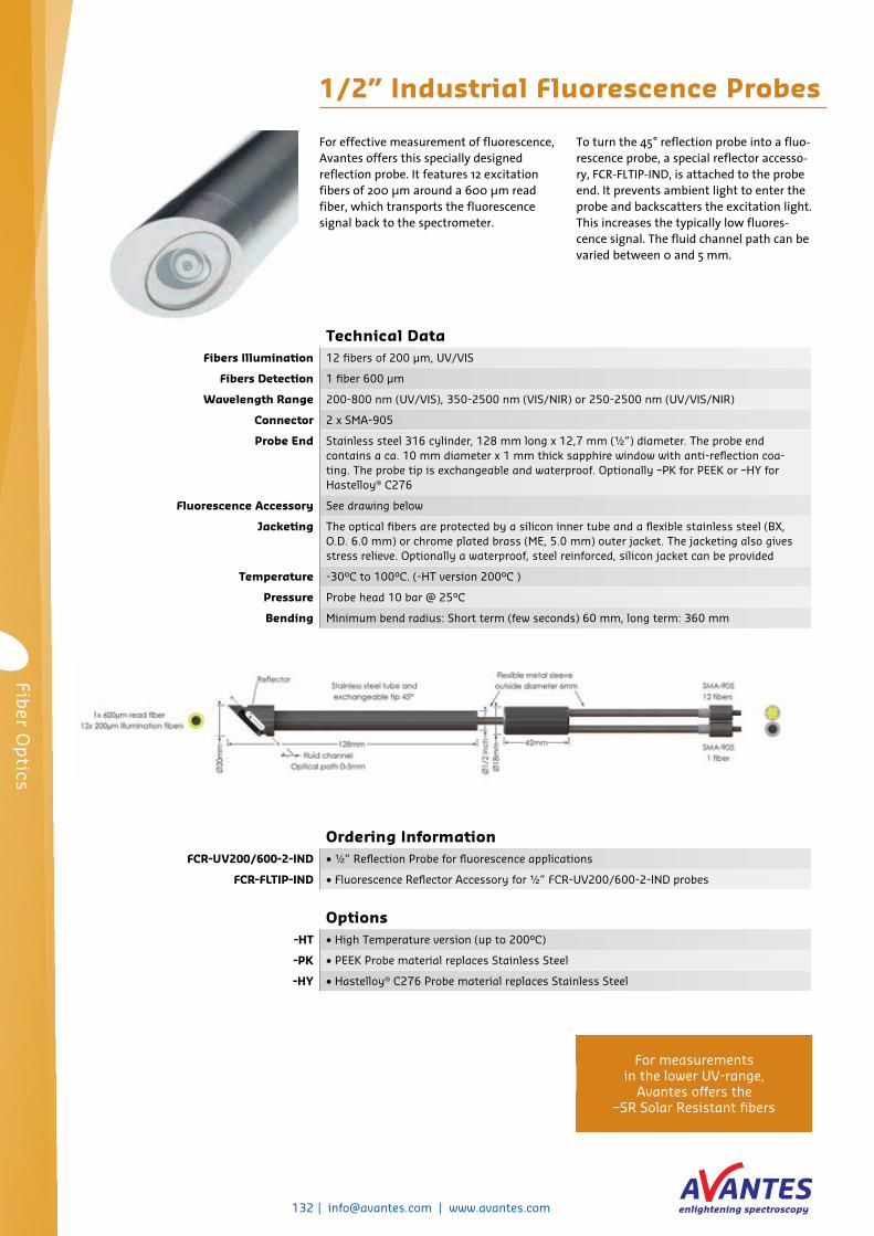
Technical DataFibers Illumination 12 fibers of 200 µm, UV/VIS
Fibers Detection 1 fiber 600 µm
Wavelength Range 200-800 nm (UV/VIS), 350-2500 nm (VIS/NIR) or 250-2500 nm (UV/VIS/NIR)
Connector 2 x SMA-905
Probe End Stainless steel 316 cylinder, 128 mm long x 12,7 mm (½”) diameter. The probe end contains a ca. 10 mm diameter x 1 mm thick sapphire window with anti-reflection coa-ting. The probe tip is exchangeable and waterproof. Optionally –PK for PEEK or –HY for Hastelloy® C276
Fluorescence Accessory See drawing below
Jacketing The optical fibers are protected by a silicon inner tube and a flexible stainless steel (BX, O.D. 6.0 mm) or chrome plated brass (ME, 5.0 mm) outer jacket. The jacketing also gives stress relieve. Optionally a waterproof, steel reinforced, silicon jacket can be provided
Temperature -30°C to 100°C. (-HT version 200°C )
Pressure Probe head 10 bar @ 25°C
Bending Minimum bend radius: Short term (few seconds) 60 mm, long term: 360 mm
For effective measurement of fluorescence, Avantes offers this specially designed reflection probe. It features 12 excitation fibers of 200 µm around a 600 µm read fiber, which transports the fluorescence signal back to the spectrometer.
To turn the 45° reflection probe into a fluo-rescence probe, a special reflector accesso-ry, FCR-FLTIP-IND, is attached to the probe end. It prevents ambient light to enter the probe and backscatters the excitation light. This increases the typically low fluores-cence signal. The fluid channel path can be varied between 0 and 5 mm.
1/2” Industrial Fluorescence Probes
Options-HT • High Temperature version (up to 200°C)
-PK • PEEK Probe material replaces Stainless Steel
-HY • Hastelloy® C276 Probe material replaces Stainless Steel
Ordering InformationFCR-UV200/600-2-IND • ½” Reflection Probe for fluorescence applications
FCR-FLTIP-IND • Fluorescence Reflector Accessory for ½” FCR-UV200/600-2-IND probes
For measurements in the lower UV-range,
Avantes offers the –SR Solar Resistant fibers
Fiber O
ptics

[email protected] | www.avantes.com | 133
Technical DataFibers 2 illumination, 1 detection fiber, all 400 µm, UV/VIS-SR
Wavelength Range 200-800 nm (UV/VIS)
Connectors 2 x SMA-905
Probe End
Stainless steel cylinder, 37 mm long x 1.6 mm (1/16”) diameter, then 63 mm x 1.8 mm. The probe end can be delivered with 3 different path lengths: 1 mm physical gap - 2 mm optical path, 2.5 mm physical gap - 5 mm optical path and 5 mm physical gap - 10 mm optical path
JacketingThe optical fibers are protected by a metal reinforced PVC outer jacket. The tubing also gives stress relieve. OD: 5.0 mm. Total probe length 1.5 m
Temperature 0 °C to 65 °C.
Bending Minimum bend radius: Short term (few seconds) 40 mm, long term: 240 mm
Micro Transmission Dip Probes
For micro-liter sampling, Avantes offers the micro transmission dip probe. It features a miniaturized tip which is 100 mm long x 1.6 mm in diameter to enable sampling in small vessels and all micro centrifuge tubes available on the market.
The micro transmission dip probe is avail-able for UV measurements from 200 to 800 nm with solarization resistant (SR) fibers. The fixed optical pathlengths avail-able are 2 mm, 5 mm or 10 mm.
The distance from the proximal end of the optical path to the distal end of the probe tip is is 7 mm. The probe has two SMA connectors (FC/PC also available) for convenient coupling to the Avantes line of spectrometers and light sources. The probe features three UV/VIS fibers of 400µm: two for illumination and one for detection.
Ordering InformationFDP-UV-micro-1-SR • 1/16” Micro Dip Probe, UV/VIS, 1 mm physical gap (2 mm optical path), 1.5 m
FDP-UV-micro-2.5-SR • As FDP-UV-micro-1-SR, but 2.5 mm physical gap (5 mm optical path)
FDP-UV-micro-5-SR • As FDP-UV-micro-1-SR, but 5.0 mm physical gap (10 mm optical path)
For the latest information, go to www.avantes.com

134 | [email protected] | www.avantes.com
Options-BX • Stainless steel jacket
-HT • High Temperature version (up to 200°C)
-HY • Hastelloy® C276 Probe material replaces Stainless Steel
For absorption measurements in minia-turized centrifuge tubes or vessels, Avantes offers the mini transmission dip probe. It features a miniaturized tip which is 130 mm long and 3.2 mm in diameter.
The mini transmission dip probe has a fixed 5 or 10 mm optical path length. It is avail-able in three different versions: one for UV/VIS (200-800 nm) measurements, one for VIS/NIR (350-2500 nm) and one for UV/VIS/NIR (250-2500 nm). For best results below 240 nm, solarization resistant fiber (-SR) is recommend. The probe features Avantes
ME, chrome plated brass, jacketing.
Optionally the probe can be configured with a longer stainless steel or Hastelloy® tip, other jacketing options (MS, BX, or PVC). The probe has two SMA connectors (FC/PC also available) for convenient cou-pling to the Avantes line of spectrometers and light sources.
Please contact us for special requirements.
Mini Transmission Dip Probes
Technical DataFibers 1 illumination and 1 detection fiber, both 200 µm, standard 2 meters length
Wavelength Range 200-800 nm (UV/VIS), 350-2500 nm (VIS/NIR) or 250-2500 nm (UV/VIS/NIR)
Connectors 2 x SMA-905
Probe End Stainless steel 316 cylinder, 130 mm long x 3.2 mm (1/8”) diameter. The probe end contains 5 mm physical, 10 mm optical path, or a 2.5 mm physical gap (5 mm optical path). Optionally –HY for Hastelloy® C276
Jacketing The optical fibers are protected by a silicon inner tube and a flexible stainless steel (optional BX, O.D. 6.0 mm) or chrome plated brass (standard ME, 5.0 mm) outer jacket. The jacketing also gives stress relieve.
Temperature -40 °C to 100 °C. (-HT version 200°C)
Pressure Probe head 10 bar @ 25°C
Bending Minimum bend radius: Short term (few seconds) 20 mm, long term: 120 mm
Ordering InformationFDP-2xx200-2-2.5-mini • 1/8” Mini Dip Probe, 2.5 mm path length (optical 5 mm), 2 m length
FDP-2xx200-2-5-mini • 1/8” Mini Dip Probe, 5 mm path length (optical 10 mm), 2 m length
Specify xx = UV for UV/VIS fiber cables, IR for VIR/NIR and UVIR for broadband UV/VIS/NIR
Fiber O
ptics

[email protected] | www.avantes.com | 135
Options-BX • Stainless steel jacket
-HT • High Temperature version (up to 200°C)
-HY • Hastelloy® C276 Probe material replaces Stainless Steel
Transmission Dip Probes
For online and inline absorbance measure-ments in fluids, transmission dip probes are used. When dipping or permanently mounting the probe end into the fluid, absorbance can be measured.
A standard SMA-905 connector is used to couple light into a fiber bundle, typically consisting out of six fibers (other configu-rations available upon request). The light is transmitted to the probe end, where it crosses the predetermined gap and is then reflected against a diffuse white reflective material back onto the receiving read fiber, which is coupled, to a spectrometer on the second leg of the probe.
The read fiber is place in the center of the illumination fiber bundle to provide the best collection efficiency for the probe. Both bundles are housed in flexible stain-less steel jacketing and the probe tip is also made of stainless steel. At the mid-point of the assembly a ferrule is used to split the fibers into their respective legs (illumi-nation and read) which are terminated in SMA-905 connectors.
All Avantes fiber-optic probes can be customized to meet your specific require-ments.
Technical DataFibers 6 illumination fibers, 1 detection fiber, all 200 µm, standard 2 meters
Wavelength range 200-800 nm (UV/VIS), 350-2500 (VIS/NIR) or 250-2500 nm (UV/VIS/NIR)
Connectors SMA-905 connectors (2x)
Tips Replacement tips are available with 1, 2.5 and 5 mm spacing, i.e. an optical path of 2,5 and 10 mm and contain a 5 mm diam. x 1 mm thick fused silica window
Probe end Stainless steel 316 cylinder, 100 mm long x 8,0 mm diameter. Waterproof , Optionally –HY for Hastelloy® C276
Jacketing The optical fibers are protected by a silicon inner tube and a flexible stainless steel (optio-nal BX, O.D. 6.0 mm) or chrome plated brass (standard ME, 5.0 mm) outer jacket. The jac-keting also gives stress relieve.
Temperature -30°C to 100°C. (-HT version 200°C)
Pressure Probe head 10 bar @ 25°C
Bending Minimum bend radius: Short term (few seconds) 20 mm, long term: 120 mm
Ordering InformationFDP-7xx200-2-yy • Transmission Dip Probe, yy (1, 2.5, 5 mm) gap, 2 m length, SMA term.
FDP-TIP-yy• Replacement tips, 1 mm, 2.5 mm, 5 mm gap for probe
(fill in gap length for yy, note optical path =2*yy)
Specify xx = UV for UV/VIS fiber cables, IR for VIR/NIR and UVIR for broadband UV/VIS/NIR

136 | [email protected] | www.avantes.com
Options-BX • Stainless steel jacket
-HT • High Temperature version (up to 200°C)
-PK • PEEK Probe material replaces Stainless Steel
-HY • Hastelloy® C276 Probe material replaces Stainless Steel
Transmission Dip Probes with Variable Path Length
For more flexibility during absorbance measurements in fluids, this fiber-optic probe features a variable and adjustable path length. The gap between the fiber and the diffuser can be set anywhere between 0.25 and 10 mm.
A standard SMA-905 connector is used to couple light into a fiber bundle, typically consisting out of six fibers (other configu-rations available upon request). The light is transmitted to the probe end, where it crosses the predetermined gap and is then reflected against a diffuse white reflective material back onto the receiving read fiber which is coupled to a spectrometer on the second leg of the probe.
The read fiber is placed in the center of the illumination fiber bundle to provide the best collection efficiency for the probe. Both bundles are housed in flexible stain-less steel jacketing and the probe tip is also made of stainless steel. At the mid-point of the assembly a ferrule is used to split the fibers into their respective legs (illu-mination or read) which are terminated in SMA-905 connectors.
All Avantes fiber-optic cables can be customized to meet your specific require-ments.
Technical DataFibers 6 illumination fibers, 1 detection fiber, all 200 µm, standard 2 meters
Wavelength range 200-800 nm (UV/VIS), 350-2500 nm (VIS/NIR) or 250-2500 nm (UV/VIS/NIR)
Connectors SMA-905 connectors (2x)
Optical Path 0.25 - 10 mm physical gap, i.e. an optical path of 0.5-20 mm
Probe end Stainless steel 316, 150-160 mm long x 12,7 mm (½”) diameter. Waterproof. Optionally –PK for PEEK or –HY for Hastelloy® C276
JacketingThe optical fibers are protected by a silicon inner tube and a flexible stainless steel (optional BX, O.D. 6.0 mm) or chrome plated brass (standard ME, 5.0 mm) outer jacket. Optionally a waterproof, steel reinforced, silicon tubing can be provided (-MS)
Temperature -30°C to 100°C. (-HT version 200°C)
Pressure Probe head 10 bar @ 25°C
Bending Minimum bend radius: Short term (few seconds) 20 mm, long term: 120 mm
Ordering InformationFDP-7xx200-2-VAR • Transmission Dip Probe in stainless steel with variable tip length, 2 m length, SMA term.
FDP-TIP-VAR • Replacement Stainless Steel tip for Transmission dip probe with variable tip length
Specify xx = UV for UV/VIS fiber cables, IR for VIR/NIR and UVIR for broadband UV/VIS/NIR
Fiber O
ptics

[email protected] | www.avantes.com | 137
For some applications a very specific fiber or probe is needed. Avantes has almost 20 years of experience in designing the custom probes for unique applications. Avantes has significant expertise in design-ing fiber-optics for high temperature (HTX), high pressure (HP), vacuum and other difficult conditions. Avantes wide variety of standard and custom materials can be configured to provide a fiber assem-bly which can meet the challenges of your environment.
Below are some examples of our special designs. Please contact us to discuss your needs.
High temperature UV/VIS/NIR probe with gas connectionThe universities of Bochum (Germany) and Utrecht (The Netherlands) approached us with a problem doing high temperature measurements at low pressure of dehydro-genation of propane: an ideal situation for the creation of cokes. Therefore every time the probe was contaminated with coke residue on the tip, meaning they could only do a single test after which they had to replace the probe.
Avantes responded by designing this high temperature probe. It’s resistant to tem-peratures of 700 degrees centigrade or more and features a connection for gas insertion into the probe. So far, during one test the probe was used over 150 hours continuously, with temperatures of 550-600 degrees. The gas used was nitrogen. The result was a clean tip, re-usable probe and very happy customers.
Chemical resistant reflection probeIn chemical environments, standard reflec-tion probes have a huge disadvantage: many chemicals interfere with the glue used to construct the probes. This version eliminates this disadvantage: all connec-tions are mechanical, sapphire windows and o-rings are used. The material used is stainless steel 310, which is chemical resis-tant as well.
A reflection probe is inserted into the back of this probe: it serves as a protective sleeve. The path length is variable and up to 30 mm.
Special Fiber Assemblies and Probes

138 | [email protected] | www.avantes.com
Technical Data COL-UV/VIS COL-90-UV/VIS COL-UV/VIS-25
Lens Diameter 6 mm 25 mm
Lens confocal length 8.7 mm 50 mm
Lens Material UV grade Fused Silica
Wavelength range 200-2500 nm
Fiber connection SMA-905, UNS 1/4” (standard, FC/PC also possible)
Mirror reflectivity n.a. >90% (200-1100 nm) n.a.
Housing Material Aluminum black anodized
Thread UNF 3/8”-24 n.a.
Temperature range -30°C to 100°C (-HT version 200°C)
COL-UV/VIS
Collimating lens
Collimating lensesTo convert divergent beams of light into a parallel beam, a collimating lens is needed. Avantes collimating lenses are optimized for the UV/VIS/NIR range (200-2500 nm) and have anodized aluminum housings.
The COL-UV/VIS and COL-90-UV/VIS have a 6 mm diameter lens with a confocal length of 8.7 mm. The COL-90-UV/VIS is used when a 90-degree exit angle is needed. The focal point for the COL-UV/VIS and
COL-90-UV/VIS can be adjusted. The COL-UV/VIS can also be ordered with an FC/PC connector.
The COL-UV/VIS-25 is the big brother of the COL-UV/VIS. It has a lens diameter of 25 mm and a confocal length of 50 mm. This larger collimating lens is suitable for collec-tion of light in free space.
Ordering InformationCOL-UV/VIS • Collimating lens for UV/VIS/NIR, incl. SMA adapter and adj. focus
COL-UV/VIS-FCPC • Collimating lens for UV/VIS/NIR, incl. FC/PC adapter, adj. focus
COL-90-UV/VIS • Collimating lens under 90 degrees for UV/VIS/NIR, incl. SMA adapter
COL-UV/VIS-25 • Collimating lens 25 mm for UV/VIS/NIR, incl. SMA adapter and adj. focus
COL-90-UV/VIS
A collimating lens can be used to collect
more light into a fiber cable
Fiber O
ptics

[email protected] | www.avantes.com | 139
Technical data
CC-UV/VIS CC-VIS/NIRCC-UV/VIS/NIR-8MM
CC-UV/VIS/NIR-5.0
Active area 3.9 mm 3.9 mm 8.0 mm 20.0 mm
Diffusing material Teflon (200-800 nm), ca. 1 mm thick
Radin Quartz (200-2500 nm), ca. 1.5 mm thick
Dimensions 6.5 mm diameter, 18 mm long 12 mm diameter, 29 mm long
38 mm diameter, 317 mm long
Sampling geometry Accepts light at/from 180° FOV Accepts light at 5° FOV
Connector SMA-905
Temperature -30 °C to +100 °C
Cosine correctors
To collect light from a 180° angle, cosine correctors are used. This eliminates opti-cal interface problems associated with the light collection sampling geometry inherent to other sampling devices such as bare fiber-optics, collimating lenses or integrat-ing spheres.
Avantes offers four different models of cosine correctors: The CC-UV/VIS and CC-VIS/NIR have a 3.9 mm active area, and dimensions of 18 mm (L) X 6.5 mm (OD). The CC-UV/VIS is made of Teflon which especially suited for measurements in the 200-800 nm range, whereas the CC-VIS/NIR covers the full UV/VIS/NIR range of
200-2500 nm and is made of Radin Quartz.
The CC-UV/VIS/NIR-8MM works as the CC-VIS/NIR, but has an active area of 8.0 mm and dimensions of 29 mm (L) X 12 mm (OD). The specialized CC-UV/VIS/NIR-5.0 has a 20 mm active area is used for solar measurement applications requiring a 5° angular field of view has a 20 mm active area and is much larger than the other cosine correctors measuring 317 mm (L) X 38 mm (OD).
Ordering InformationCC-UV/VIS • Cosine Corrector for UV/VIS, incl. SMA adapter
CC-VIS/NIR • Cosine Corrector for UV/VIS/NIR, incl. SMA adapter
CC-UV/VIS/NIR-8MM • Cosine Corrector for UV/VIS/NIR, 8 mm area, incl. SMA adapter
CC-UV/VIS/NIR-5.0 • Cosine Corrector for UV/VIS/NIR, 5.0° FOV, incl. SMA adapter
CC-VIS/NIR
A cosine corrector collects light from an angle of 180°, ideal in situations
with scattered light
140 | [email protected] | www.avantes.com
Options-HT • High Temperature version (up to 200°C)
-SR• Solarization resistant fibers for DUV <250 nm applications (in combination with 100-600
µm UV fibers only)
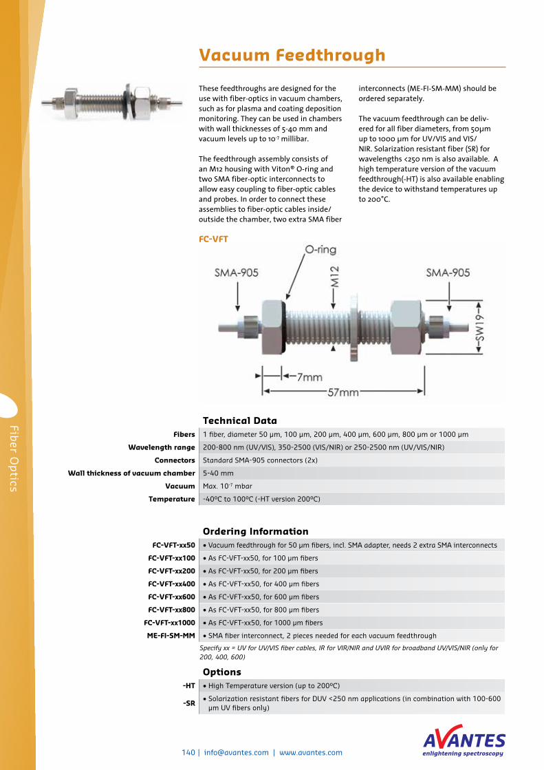
Vacuum Feedthrough
These feedthroughs are designed for the use with fiber-optics in vacuum chambers, such as for plasma and coating deposition monitoring. They can be used in chambers with wall thicknesses of 5-40 mm and vacuum levels up to 10-7 millibar.
The feedthrough assembly consists of an M12 housing with Viton® O-ring and two SMA fiber-optic interconnects to allow easy coupling to fiber-optic cables and probes. In order to connect these assemblies to fiber-optic cables inside/outside the chamber, two extra SMA fiber
interconnects (ME-FI-SM-MM) should be ordered separately.
The vacuum feedthrough can be deliv-ered for all fiber diameters, from 50µm up to 1000 µm for UV/VIS and VIS/NIR. Solarization resistant fiber (SR) for wavelengths <250 nm is also available. A high temperature version of the vacuum feedthrough(-HT) is also available enabling the device to withstand temperatures up to 200°C.
Technical DataFibers 1 fiber, diameter 50 µm, 100 µm, 200 µm, 400 µm, 600 µm, 800 µm or 1000 µm
Wavelength range 200-800 nm (UV/VIS), 350-2500 (VIS/NIR) or 250-2500 nm (UV/VIS/NIR)
Connectors Standard SMA-905 connectors (2x)
Wall thickness of vacuum chamber 5-40 mm
Vacuum Max. 10-7 mbar
Temperature -40°C to 100°C (-HT version 200°C)
Ordering InformationFC-VFT-xx50 • Vacuum feedthrough for 50 µm fibers, incl. SMA adapter, needs 2 extra SMA interconnects
FC-VFT-xx100 • As FC-VFT-xx50, for 100 µm fibers
FC-VFT-xx200 • As FC-VFT-xx50, for 200 µm fibers
FC-VFT-xx400 • As FC-VFT-xx50, for 400 µm fibers
FC-VFT-xx600 • As FC-VFT-xx50, for 600 µm fibers
FC-VFT-xx800 • As FC-VFT-xx50, for 800 µm fibers
FC-VFT-xx1000 • As FC-VFT-xx50, for 1000 µm fibers
ME-FI-SM-MM • SMA fiber interconnect, 2 pieces needed for each vacuum feedthrough
Specify xx = UV for UV/VIS fiber cables, IR for VIR/NIR and UVIR for broadband UV/VIS/NIR (only for 200, 400, 600)
FC-VFT
Fiber O
ptics

[email protected] | www.avantes.com | 141
When connecting a multi-furcated fiber to a spectrometer or light source, light entering/exiting each of the fiber legs may or may not be uniform, so a fiber-optic homogenizer can be used to mix the sig-nals to provide more uniform signal.
The compact MMA-UV/VIS-SMA fiber-optic homogenizer is made of anodized alumi-num and has female SMA-905 connectors on both ends. Internally, a highly transmis-sive Suprasil-Rod with a diameter of 1 or
3 mm transmits the light from one end to the other (from bundle to single fiber) and perfectly mixes the modes.
The fiber-optic homogenizer can also be used as a mode stripper.
Technical dataWavelength Range 200-2000 nm
Optical Rod Diameter Stabdurchmesser 3 mm or 1 mm
Lens Material Suprasil 1
Housing Material l Aluminum anodized
Fiber Connection SMA-905, UNS 1/4”
Dimensions Length 47.5 mm, Diameter 14 mm
Temperature -30 °C to +100 °C
MMA-UV/VIS-SMA Homogenizer
Fiber-optic Homogenizer
Ordering InformationMMA1-UV/VIS-SMA • Homogenizer / Modestripper 1 mm UV/VIS diameter for SMA Connectors
MMA3-UV/VIS-SMA • Homogenizer / Modestripper 3 mm UV/VIS diameter for SMA Connectors
Ordering InformationAVS-MFA-SMA • C-mount adapter for Olympus, SMA connector
AVS-CMOUNT-SMA • C-mount adapter, SMA connector
AVS-CMOUNT-FCPC • C-mount adapter, FC/PC connector
Fiber Microscope Adapters
To easily mount an Avantes fiber-optic spectrometer to a microscope, a C-mount adapter is available. It connects to an SMA or FC/PC fiber-optic cable and features an outside diameter of 38 mm, 35 mm long to
slide inside the tube of a microscope.A special adapter with C-mount 1 inch-32 thread is available as AVS-MFA-SMA to screw onto a microscope.
Technical DataAVS-MFA-SMA AVS-CMOUNT-SMA AVS-CMOUNT-FCPC
Fiber-optic connection SMA SMA FC/PC
Microscope mount 1 inch-32 Cmount thread 38 mm diameter 38 mm diameter
Material Black anodized aluminum

142 | [email protected] | www.avantes.com
Ordering InformationRPH-1 • Reflection probe holder for 45/90 degree mounting of 6.5 mm reflection probes
AFH-15• Angled fiber probe holder for measuring under different angles, needs 1.5 mm ferrule
terminated fibers.
FC-UV200-2-1.5x40• Fiber cable, 200 µm UV/VIS fiber, 2 m long, one end with SMA connector, other end with
stainless steel ferrule, OD=1.5 mm x 40 mm length.
AFH-Ocular • Angled fiber probe holder for precise measurements under 45 degrees incl. Ocular
FCR-7UV100-2-1x25• Reflection probe with 7x100 µm UV/VIS fibers to 1x25 mm stainless steel ferrule,
2 meter long with PVC/Kevlar protection sleeve and 2 SMA connectors
RPH-1 Reflection Probe Holder The RPH-1 is to be used with our standard reflection probes, which are 6.5 mm in diameter. The holder enables positioning of the probe tip in two angles: 45 degrees for diffuse reflection measurements and 90 degrees (normal to sample) for specular reflection. This assembly is mostly used to facilitate color measurements.
A setscrew is included to mount the probe into position. The RPH-1 is a small device, measuring only 60 by 30 by 30 millimeters. It’s made of black anodized aluminum.
Reflection Probe Holders
AFH-15 Angled Fiber Holder To do an angled measurement with a small 1.5 mm reflection probe or 1.5 mm stainless steel ferrule terminated fibers, the AFH-15 is the ideal accessory. Offering angles including 15°, 30°, 45°, 60°, 75° and 90°, reflection measurements with differing incident and collection angle can be easily
made with multiple , separate fibers for illumination and detection.
All 11 holes have a diameter of 1.6 mm and are equipped with a setscrew to mount the probes or fibers into position. The AFH-15 is made of black anodized aluminum.
AFH-OcularMeasurements on a small spot (less than 0.5 mm) can be challenging but the AFH-Ocular makes the job easier. The ocular enables visual location of the measure-ment spot on your sample. The holder is used in conjuction with our miniaturized reflection probe (FCR-7UV100-2-1x25) which has 7 x 100 µm fibers in a 6 around
1 configuration and the tip is 1 mm in diam-eter x 25 mm long.
Please note that a black cover over the ocular (not included) should be used during measuring to prevent ambient light from reaching the measurement spot.
Three years limited warranty on all Avantes spectrometers,
light sources and accessories
Fiber O
ptics

[email protected] | www.avantes.com | 143
For easy and accurate reflection and transmission measurements of glass and thinfilm, the Avantes Stage is the ideal companion. With a height of 420 mm and three individually adjustable devices, almost any measurement can be accom-plished. The three devices are a rotatable entrance disc, with openings for an SMA fiber (with collimating lens) and different sizes reflection probes. The second and
third devices are sample holders, that are used for the transmission or reflection measurement. For scattering transmission measurements, an AvaSphere integrating sphere of 30 or 50 mm can be installed.
Transmission and Reflection Stage
Ordering informationTransmission-stage • Transmission and reflection stage, 420 mm high
144 | [email protected] | www.avantes.com
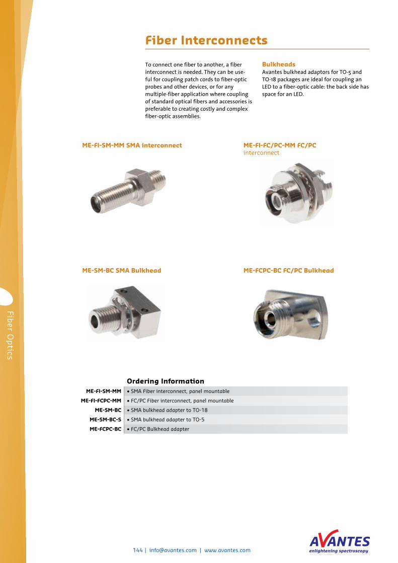
Ordering InformationME-FI-SM-MM • SMA Fiber interconnect, panel mountable
ME-FI-FCPC-MM • FC/PC Fiber interconnect, panel mountable
ME-SM-BC • SMA bulkhead adapter to TO-18
ME-SM-BC-S • SMA bulkhead adapter to TO-5
ME-FCPC-BC • FC/PC Bulkhead adapter
Fiber Interconnects
ME-FI-SM-MM SMA interconnect
ME-FCPC-BC FC/PC BulkheadME-SM-BC SMA Bulkhead
ME-FI-FC/PC-MM FC/PC interconnect
To connect one fiber to another, a fiber interconnect is needed. They can be use-ful for coupling patch cords to fiber-optic probes and other devices, or for any multiple-fiber application where coupling of standard optical fibers and accessories is preferable to creating costly and complex fiber-optic assemblies.
BulkheadsAvantes bulkhead adaptors for TO-5 and TO-18 packages are ideal for coupling an LED to a fiber-optic cable: the back side has space for an LED.
Fiber O
ptics