fiber optic flame detection system - forney corporation · fiber optic flame detection system...
TRANSCRIPT

FlameHawk® Model 0705AD
Fiber Optic Flame Detection System Publication 372001-14 Rev A

FlameHawk® Operation Manual
372001-14 Rev A
i
INTRODUCTION This manual contains information for the FlameHawk® Fiber Optic Flame Detector from Forney
Corporation, 16479 North Dallas Parkway, Suite 600 Addison, TX 75001.
All personnel should become thoroughly familiar with the contents of this manual before attempting to
install, operate or maintain the FlameHawk® Fiber Optic Flame Detector system. Because it is virtually
impossible to cover every situation that might occur during operation and maintenance of the equipment
described in this publication, personnel are expected to use good engineering judgment when confronted
with situations that are not specifically mentioned herein.
The user should update this manual whenever significant changes are made to the system. To be of value,
the manual must always reflect the latest configuration of the equipment. It should be noted, however,
that Forney Corporation will furnish updated pages only if Forney authorizes a modification and
accomplished under Forney supervision.
PROPRIETARY NOTICE The contents of this publication are proprietary data of Forney Corporation. Reproduction or use of any
part of the publication for purposes other than the support of the equipment for which it is published is
permissible only if expressly authorized in writing by Forney.
Additional copies of this publication may be purchased from Forney. When ordering or requesting cost
information, refer to the publication number appearing on the title page. Address to the attention of the
Sales Department, Forney Corporation, 16479 North Dallas Parkway, Suite 600 Addison, TX 75001.
Revisions
Revision Date Comments
A 10/02/2014 Initial Release
FlameHawk® Operation Manual
372001-14 Rev A
ii
Table of Contents
Section 1 System Description ...................................................................................... 1
1.1 Introduction ...................................................................................................................................... 1
1.2 Operational Overview ....................................................................................................................... 1
1.3 Detailed Specifications ..................................................................................................................... 2
1.4 Component Descriptions .................................................................................................................. 3
1.5 Electronics Module ........................................................................................................................... 3
1.6 Flame Sight Assemblies (FSAs) ...................................................................................................... 4 1.6.1 Aeroderivative Engine FSA ................................................................................................. 4 1.6.2 Frame Engine FSA Threaded ............................................................................................. 4 1.6.3 Frame Engine FSA – Flange Design .................................................................................. 5
1.7 Fiber Optic Cables ........................................................................................................................... 6
Section 2 System Installation ....................................................................................... 7
2.1 Installation ........................................................................................................................................ 7
2.2 FSA Installation Procedure .............................................................................................................. 7 2.2.1 Aeroderivative Engine FSA ................................................................................................. 7 2.2.2 Frame Engine FSA – Threaded .......................................................................................... 8 2.2.3 Frame Engine FSA – Flange Design .................................................................................. 8
2.3 Fiber Optic Installation ..................................................................................................................... 9
2.4 Electronics Installation ................................................................................................................... 10
2.5 System Installation Wiring .............................................................................................................. 11 2.5.1 Setup for 4-20mA Operation ............................................................................................. 12 2.5.2 Set-Up for Relay Operation ............................................................................................... 13 2.5.3 Set-Up for Simultaneous 4-20mA and Relay Operation ................................................... 14
Section 3 Maintenance Procedures ........................................................................... 15
3.1 Recommended Cleaning Materials ................................................................................................. 15
3.2 Procedure for Electronics End Optics ............................................................................................. 15
3.3 Procedure for Cleaning Combustor End Optics .............................................................................. 16 3.3.1 Aeroderivative Type FSA .................................................................................................. 16 3.3.2 Frame Engine Type FSA .................................................................................................. 16
Section 4 System Troubleshooting ........................................................................... 17
List of Figures
Figure 1 Aeroderivative FSA .......................................................................................................................... 4 Figure 2 Frame FSA Installation Primary Zone .............................................................................................. 5 Figure 3 Frame Engine FSA with CDP Purge Fitting ...................................................................................... 5 Figure 4 Frame Engine FSA Flange Design ................................................................................................... 5 Figure 5 Fiber Optic Cable Compression Fitting ............................................................................................ 6 Figure 6 GE Frame Engine FSA, Typical Primary Zone Installation............................................................. 8 Figure 7 Frame Engine FSA, Typical Secondary Zone Installation .............................................................. 9 Figure 8 MS38999 Connector Pin Detail .................................................................................................... 12
List of Tables
Table 1 Wiring Information .......................................................................................................................... 11

FlameHawk® Operation Manual
372001-14 Rev A
1
Section 1 System Description
1.1 Introduction The Model 0705AD FlameHawk
® flame detection system is a dual channel solid-state device designed
for direct replacement of Geiger-Mueller (GM) tube flame sensors and other solid-state detection systems
used on industrial and marine gas turbine engines.
Based upon many years of laboratory and field testing, the Model 0705AD significantly improves
performance and reduces maintenance costs of flame sensors used on Frame and Aeroderivative gas
turbine engines. The innovative approach incorporates durable fiber optic cables to transmit the spectral
energy from the combustion process to the electronic module. This feature allows for remote mounting of
electronics module, outside of the engine enclosure, thereby eliminating complicated cooling systems
common in other flame sensors.
The Model 0705AD will work in low NOx combustors, multiple fuel applications, and with systems
incorporating steam injection. No special calibration or field adjustment is required for installation.
Additional applications include:
Industrial Boiler Flame Detection
Auto-ignition and Flashback Detection
Engine Acoustical Analysis
Combustion Dynamic Analysis
1.2 Operational Overview The Model 0705AD FlameHawk
® flame detection system is sensitive to spectral energy from 300nm to
450nm. Flame radiation is received through a sealed lens assembly that focuses the energy onto a fiber
optic cable. The fiber optic cable transmits the spectral energy to the remote mounted electronics module.
The signal conditioning circuitry in the electronics module processes the spectral energy and provides
relay and 4-20 mA outputs. Two signal strength meters incorporating LED arrays are included with the
electronics module and are visible through the cover of the enclosure. The electronics module can be
operated in two different modes depending on how the unit is wired at installation.
1) When the electronics module is connected to a 18 to 32 VDC power source, it can be operated
simultaneously with 4-20 mA and relay outputs.
2) The module can also be operated in a stand-alone 4-20 mA two wire loop-powered circuit mode. The
signal strength meter is operational only when 18 to 32 VDC power is present.
The fiber optic cables and optical probes have been designed for easy installation and maintainability.
Simple threaded connections are used throughout the system to allow for rapid installation without the
need for special tooling. Unique features, such as a quick-release clamp on the Frame engine optical
probe, have been incorporated to ease cleaning and inspection.
FlameHawk® Operation Manual
372001-14 Rev A
2
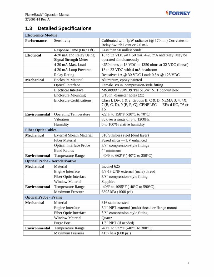
1.3 Detailed Specifications
Electronics Module
Performance Sensitivity: Calibrated with 1μW radiance (@ 370 nm) Correlates to
Relay Switch Point or 7.0 mA
Response Time (On / Off) Less than 50 milliseconds
Electrical 4-20 mA and Relay Using
Signal Strength Meter
18 to 32 VDC @ > 50 mA, 4-20 mA and relay. May be
operated simultaneously
4-20 mA Max. Load <650 ohms at 18 VDC to 1350 ohms at 32 VDC (linear)
4-20 mA Loop Powered 18 to 32 VDC with 4 mA headroom
Relay Rating Resistive: 1A @ 30 VDC Load: 0.5A @ 125 VDC
Mechanical Enclosure Material Aluminum, epoxy painted
Optical Interface Female 3/8 in. compression-style fitting
Electrical Interface MS38999 / 20WD97PN or 3/4” NPT conduit hole
Enclosure Mounting 5/16 in. diameter holes (2x)
Enclosure Certifications Class I, Div. 1 & 2, Groups B, C & D; NEMA 3, 4, 4X,
7 (B, C, D), 9 (E, F, G); CENELEC — EEx d IIC, T6 or
T5
Environmental Operating Temperature -22°F to 158°F (-30°C to 70°C)
Vibration 8g over a range of 5 to 1200Hz
Humidity 0 to 100% relative humidity
Fiber Optic Cables
Mechanical External Sheath Material 316 Stainless steel (dual layer)
Fiber Material Fused silica — UV enhanced
Optical Interface Probe 3/8” compression-style fittings
Bend Radius 4” minimum
Environmental Temperature Range -40°F to 662°F (-40°C to 350°C)
Optical Probe - Aeroderivative
Mechanical Material Inconel 625
Engine Interface 5/8-18 UNF external (male) thread
Fiber Optic Interface 3/8” compression-style fitting
Window Material Sapphire
Environmental Temperature Range -40°F to 1095°F (-40°C to 590°C)
Maximum Pressure 6895 kPa (1000 psi)
Optical Probe - Frame
Mechanical Material 316 stainless steel
Engine Interface 3/4” NPT external (male) thread or flange mount
Fiber Optic Interface 3/8” compression-style fitting
Window Material Quartz
Purge Port 1/8” NPT (if needed)
Environmental Temperature Range -40°F to 572°F (-40°C to 300°C)
Maximum Pressure 4137 kPa (600 psi)

FlameHawk® Operation Manual
372001-14 Rev A
3
1.4 Component Descriptions The Model 0705AD FlameHawk
® flame detection system shall consist of the following components:
An electronics module with a built-in signal strength meter that indicates flame intensity by the
number of LEDs lit in an array of ten per channel.
Two flexible fiber optic cables that transmit NUV/Vis radiation from the combustion zone to the
photovoltaic sensor.
Two flame sight assemblies (FSA) for interfacing between the fiber optic cables and the combustion
chamber.
1.5 Electronics Module The electronic circuitry is mounted in a modified NEMA 3, 4, 4X, 7(B,C,D), 9(E,F,G) explosion and
weather-proof cast aluminum enclosure consisting of a housing and a cover. The cover contains a
window for viewing the LED arrays and is sealed with a heavy glass window and gasket. The cover is
threaded into the housing and securely sealed with a Nitrile O-ring.
The housing has three fittings for the optical and electrical connections. The electrical connection is
Electronics Module
Aeroderivative-Style FSA
Frame-Style FSA
Fiber Optic Cables
LED Indicators
FlameHawk® Operation Manual
372001-14 Rev A
4
made through a single connector conforming to MS38999/20WD97PN or a ¾” NPT conduit port. The
opposite side of the housing has two compression-style fittings. The compression-style fittings mate the
fiber optic cables to the housing and provide a seal that protects the fiber optic cable and photovoltaic
sensor from the outside environment.
The electronics module within the Model 0705AD is made up of four printed circuit boards (PCB's)
enclosed in a metal housing. The PCB's include a display board, terminal board, and two signal
conditioning boards (one for each channel). None of the aforementioned PCB's are user serviceable, as
the module is factory calibrated and sealed.
1.6 Flame Sight Assemblies (FSAs) Four options of flame sight assemblies can be used with the Model 0705AD flame detection system.
They are as follows:
00705-0185-0001: Aeroderivative FSA
00705-0212-0001: Frame Engine Primary FSA-Threaded
00705-0213-0001: Frame Engine Primary FSA- Long Focal Length
00705-0239-0001: Frame Engine Secondary FSA-Flange mount
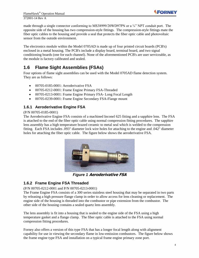
1.6.1 Aeroderivative Engine FSA
(P/N 00705-0185-0001)
The Aeroderivative Engine FSA consists of a machined Inconel 625 fitting and a sapphire lens. The FSA
is attached to the end of the fiber optic cable using normal compression fitting procedures. The sapphire
lens assembly has a high temperature brazed ceramic to metal seal which is welded to the compression
fitting. Each FSA includes .093" diameter lock wire holes for attaching to the engine and .042" diameter
holes for attaching the fiber optic cable. The figure below shows the aeroderivative FSA.
Figure 1 Aeroderivative FSA
1.6.2 Frame Engine FSA Threaded
(P/N 00705-0212-0001 and P/N 00705-0213-0001)
The Frame Engine FSA consists of a 300 series stainless steel housing that may be separated in two parts
by releasing a high pressure flange clamp in order to allow access for lens cleaning or replacement. The
engine side of the housing is threaded into the combustor or pipe extension from the combustor. The
other side of the housing contains a sealed quartz lens assembly.
The lens assembly is fit into a housing that is sealed to the engine side of the FSA using a high
temperature gasket and a flange clamp. The fiber optic cable is attached to the FSA using normal
compression fitting procedures.
Forney also offers a version of this type FSA that has a longer focal length along with alignment
capability for use in viewing the secondary flame in low-emission combustors. The figure below shows
the frame engine type FSA and installation on a typical frame engine primary zone port.

FlameHawk® Operation Manual
372001-14 Rev A
5
Figure 2 Frame FSA Installation Primary Zone
In climates with high relative humidity or in applications where engines are operated in peaking service, a
bleed air purge fitting can be installed. This feature allows CDP air to be used to remove moisture from
the FSA optical surfaces.
Figure 3 Frame Engine FSA with CDP Purge Fitting
1.6.3 Frame Engine FSA – Flange Design
(P/N 00705-0239-0001)
The Frame Engine FSA incorporating a flange is designed for installations where a standard flange
conforming to GE Frame engine interface is used for mounting the flame detection system to the
secondary flame port. The construction of this FSA is identical to the threaded frame engine FSA
described in the previous section. However, this FSA incorporates a high pressure flange for the engine
interface.
Figure 4 Frame Engine FSA Flange Design
FlameHawk® Operation Manual
372001-14 Rev A
6
1.7 Fiber Optic Cables Four standard options of fiber optic cables can be used with the Model 0705AD flame detection system.
They are as follows:
00705-0192-0120: Cable, 10 Feet Long
00705-0192-0180: Cable, 15 Feet Long
00705-0192-0300: Cable, 25 Feet Long
00705-0192-0480: Cable, 40 Feet Long
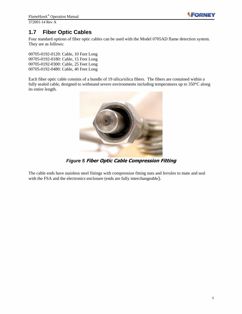
Each fiber optic cable consists of a bundle of 19 silica/silica fibers. The fibers are contained within a
fully sealed cable, designed to withstand severe environments including temperatures up to 350°C along
its entire length.
Figure 5 Fiber Optic Cable Compression Fitting
The cable ends have stainless steel fittings with compression fitting nuts and ferrules to mate and seal
with the FSA and the electronics enclosure (ends are fully interchangeable).
FlameHawk® Operation Manual
372001-14 Rev A
7
Section 2 System Installation
The Model 0705AD FlameHawk® flame detection system is designed to be installed and operated without
any special setup. Once the unit has been installed, as instructed below, the unit will provide a "flame on"
signal (greater than 4 mA) when flame is present and a "no flame" signal (less than 4 mA) when flame is
absent.
Similarly, when the relay configuration is used, the presence of spectral energy indicating flame will close
the contact on the relay (approximately 7mA). A loss of flame signal will provide an open indication on
the relay channel.
Each of the two channels can be monitored via a signal strength meter. The meter contains a series of 10
LEDs that may be used for determining if:
1) There is 18–32 VDC connected to the unit and active
2) There is sufficient flame radiation for a “flame on" signal
3) The optics require cleaning.
Note: For the LED display to function there must be 24v power on the unit's Power Input/Power Return
terminals.
2.1 Installation The Model 0705AD FlameHawk
® flame detection system installation may be divided into three basic
parts: FSA installation, fiber optic cable installation, and the electronics module mounting/installation. In
general, any of the three components may be installed separately, however, since the cable is a fixed
length the best approach is to install the FSA, attach the cable to the FSA, then attach the cable to
supports along its path, and install the electronics module.
2.2 FSA Installation Procedure
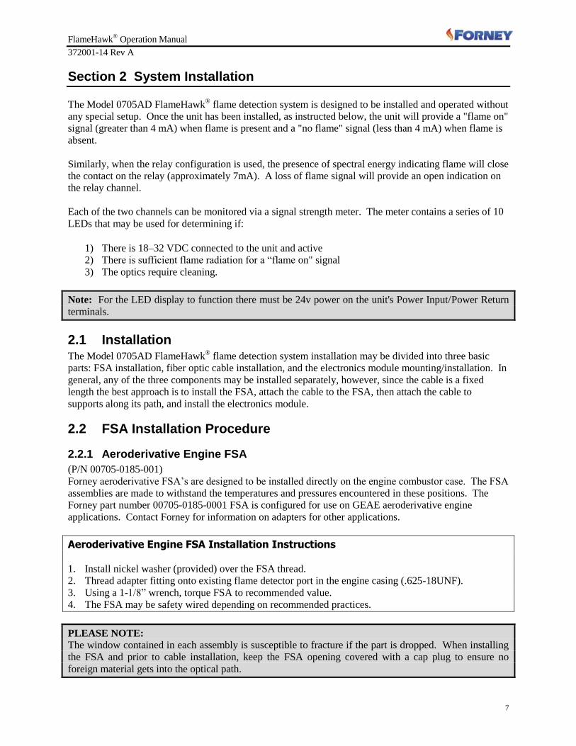
2.2.1 Aeroderivative Engine FSA
(P/N 00705-0185-001)
Forney aeroderivative FSA’s are designed to be installed directly on the engine combustor case. The FSA
assemblies are made to withstand the temperatures and pressures encountered in these positions. The
Forney part number 00705-0185-0001 FSA is configured for use on GEAE aeroderivative engine
applications. Contact Forney for information on adapters for other applications.
Aeroderivative Engine FSA Installation Instructions 1. Install nickel washer (provided) over the FSA thread.
2. Thread adapter fitting onto existing flame detector port in the engine casing (.625-18UNF).
3. Using a 1-1/8” wrench, torque FSA to recommended value.
4. The FSA may be safety wired depending on recommended practices.
PLEASE NOTE:
The window contained in each assembly is susceptible to fracture if the part is dropped. When installing
the FSA and prior to cable installation, keep the FSA opening covered with a cap plug to ensure no
foreign material gets into the optical path.

FlameHawk® Operation Manual
372001-14 Rev A
8
2.2.2 Frame Engine FSA – Threaded
(P/N 00705-0212-001 and P/N 00705-0213-0001)
The threaded frame engine FSA incorporates a males ¾” NPT for interface to the combustion system on
frame engines.
Figure 6 GE Frame Engine FSA, Typical Primary Zone Installation
Frame Engine FSA – Threaded Installation Instructions
1. Remove the safety pin from clamp and loosen the clamp (9/16” hex bolt) to allow removal.
2. Carefully remove the fiber optic-side of FSA and then the lens assembly.
3. Install a new gasket on the engine side of the FSA. A new gasket should be used each time the flange
is disconnected.
4. Check to ensure lens is clean. If not, soak clean cotton swab in alcohol and wipe the lens on both
sides. Use care not to leave cotton residue. Use multiple swabs if required to remove all visual signs
of contamination (do not re-use dirty swabs). Blow-dry with compressed air or nitrogen or use a new
swab to dry the lens surface.
5. Mount the engine side of FSA onto the mating flange and attach with appropriate hardware
conforming to the engine requirements.
6. Insert the lens assembly into the engine-mounted part of the FSA.
7. Mate the fiber optic-side of the FSA onto the lens assembly.
8. Install a new gasket between the two mating flanges of the FSA. Place clamp over the mating flanges
and tighten clamp to 100 in-lbs (make sure lock washer is outside clamp and safety pin lanyard is
held between clamp halves).
9. Insert safety pin into the clamp.
2.2.3 Frame Engine FSA – Flange Design
(P/N 00705-0239-0001)
The flange design of the frame engine FSA incorporates a standard interface flange used on secondary
flame ports on GE frame engines.

FlameHawk® Operation Manual
372001-14 Rev A
9
Figure 7 Frame Engine FSA, Typical Secondary Zone Installation
Frame Engine FSA – Flange Design Installation Instructions 1. Remove the safety pin from clamp and loosen the clamp (9/16” hex bolt) to allow removal.
2. Carefully remove the fiber optic-side of FSA and then the lens assembly.
3. Install a new gasket on the engine side of the FSA. A new gasket should be used each time the flange
is disconnected.
4. Check to ensure lens is clean. If not, soak clean cotton swab in alcohol and wipe the lens on both
sides. Use care not to leave cotton residue. Use multiple swabs if required to remove all visual signs
of contamination (do not re-use dirty swabs). Blow-dry with compressed air or nitrogen or use a new
swab to dry the lens surface.
5. Mount the engine side of FSA onto the mating flange and attach with appropriate hardware
conforming to the engine requirements.
6. Insert the lens assembly into the engine-mounted part of the FSA.
7. Mate the fiber optic-side of the FSA onto the lens assembly.
8. Install a new gasket between the two mating flanges of the FSA. Place clamp over the mating flanges
and tighten clamp to 100 in-lbs (make sure lock washer is outside clamp and safety pin lanyard is
held between clamp halves).
9. Insert safety pin into the clamp.
2.3 Fiber Optic Installation Each of the fiber optic cables consists of a 19 fiber bundle that is encased in a stainless steel flexible
conduit. The conduit protects the cable from damage and provides for attachment of the end fittings. The
cables have a minimum bend radius of 4 inches.
The cable can withstand a tensile load that is inversely proportional to its length. The cable can withstand
a 400 lb. load for a one foot free length. Sustainable tensile load can be estimated as follows:
LOADLENGTH
400
(For a 2 foot free length it can withstand 200 lbs., for a 25 foot free length it can withstand 16 lbs., etc.)
The ends of each of the fiber optic cables are identical. The fiber optic cable is intended to be installed
FlameHawk® Operation Manual
372001-14 Rev A
10
similar to an electrical cable. It can be laid in a cable trough, placed in a rigid conduit, or clamped to a
surface.
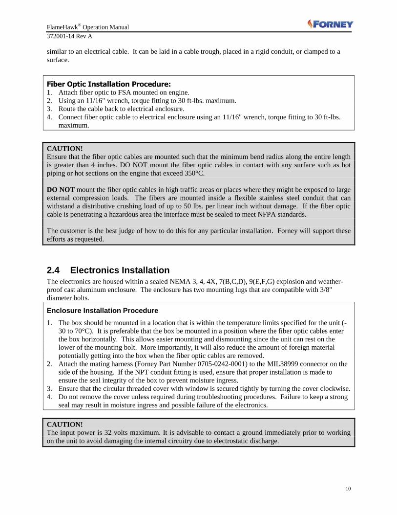
Fiber Optic Installation Procedure: 1. Attach fiber optic to FSA mounted on engine.
2. Using an 11/16" wrench, torque fitting to 30 ft-lbs. maximum.
3. Route the cable back to electrical enclosure.
4. Connect fiber optic cable to electrical enclosure using an 11/16" wrench, torque fitting to 30 ft-lbs.
maximum.
CAUTION!
Ensure that the fiber optic cables are mounted such that the minimum bend radius along the entire length
is greater than 4 inches. DO NOT mount the fiber optic cables in contact with any surface such as hot
piping or hot sections on the engine that exceed 350°C.
DO NOT mount the fiber optic cables in high traffic areas or places where they might be exposed to large
external compression loads. The fibers are mounted inside a flexible stainless steel conduit that can
withstand a distributive crushing load of up to 50 lbs. per linear inch without damage. If the fiber optic
cable is penetrating a hazardous area the interface must be sealed to meet NFPA standards.
The customer is the best judge of how to do this for any particular installation. Forney will support these
efforts as requested.
2.4 Electronics Installation The electronics are housed within a sealed NEMA 3, 4, 4X, 7(B,C,D), 9(E,F,G) explosion and weather-
proof cast aluminum enclosure. The enclosure has two mounting lugs that are compatible with 3/8"
diameter bolts.
Enclosure Installation Procedure
1. The box should be mounted in a location that is within the temperature limits specified for the unit (-
30 to 70°C). It is preferable that the box be mounted in a position where the fiber optic cables enter
the box horizontally. This allows easier mounting and dismounting since the unit can rest on the
lower of the mounting bolt. More importantly, it will also reduce the amount of foreign material
potentially getting into the box when the fiber optic cables are removed.
2. Attach the mating harness (Forney Part Number 0705-0242-0001) to the MIL38999 connector on the
side of the housing. If the NPT conduit fitting is used, ensure that proper installation is made to
ensure the seal integrity of the box to prevent moisture ingress.
3. Ensure that the circular threaded cover with window is secured tightly by turning the cover clockwise.
4. Do not remove the cover unless required during troubleshooting procedures. Failure to keep a strong
seal may result in moisture ingress and possible failure of the electronics.
CAUTION!
The input power is 32 volts maximum. It is advisable to contact a ground immediately prior to working
on the unit to avoid damaging the internal circuitry due to electrostatic discharge.

FlameHawk® Operation Manual
372001-14 Rev A
11
2.5 System Installation Wiring The Model 0705AD FlameHawk
® electronics unit can operate in 4 to 20mA mode, dry contact mode, or
both (4-20mA and dry contact) modes simultaneously. The wiring, configuration and verification steps for
each mode are described in the following sections:
Table 1 Wiring Information
Connector Pin
Internal Terminal Strip
Parameter
A 1 Channel 1: 4 – 20 mA Return
B 2 Channel 1: 4 – 20 mA Input
C 3 Channel 1: Relay
M 4 Channel 1: Relay
D 5 Power Input
E 6 Case Ground
F 7 Power Return
H 8 Channel 2: 4 – 20 mA Input
J 9 Channel 2: 4 – 20 mA Return
G 10 Channel 2: Relay
L 11 Channel 2: Relay
K Open Open

FlameHawk® Operation Manual
372001-14 Rev A
12
Figure 8 MS38999 Connector Pin Detail
2.5.1 Setup for 4-20mA Operation
The Model 0705AD FlameHawk® electronics unit can be wired for 4-20mA operation by simply
completing a 4-20mA current loop on each channel. The FlameHawk® does not require 24V power on the
Power Input and Power Return terminals (5 & 7) for 4-20mA operation. Note however, that the on-board
signal strength meter (10 segment LED) display requires that the electronics be powered. Refer to the figure
below for 4-20mA wiring detail and terminal designations:
Model 0705AD - Configured for 4 – 20 mA Loop
Channel 1
Milliammeter
Channel 2
Milliammeter
Turbine Engine Control Room
DC Power Supply
18 – 32 VDC
Positive Return
1 2 3 4 5 6 7 8 9 10 11 12
Channel 1
4-20 mA Input
Channel 1
4-20 mA Return
Channel 1
Relay
Channel 1
Relay
Power Input
Case Ground
Power Return
Channel 2
4-20 mA Input
Channel 2
4-20 mA Return
Channel 2
Relay
Channel 2
RelayOpen
A B C M D E F H J G L KConnector Pin
Parameter
Terminal Strip
0705AD Electronics Box

FlameHawk® Operation Manual
372001-14 Rev A
13
2.5.2 Set-Up for Relay Operation
Relay operating (dry contact) mode requires that power be applied to the Power Input and Power Return
terminals (5 &7). This provides both the energizing current to operate the relay coil as well as the power
to illuminate the LED signal strength display. Channel 1 connections (terminals 3 & 4) and Channel 2
connections (terminals 10 & 11) may be made without regard to +/- polarity as the relay devices are not
polarity sensitive. Refer to the figure below for Relay mode wiring detail and terminal designations:
Model 0705AD - Configured for Relay Output
10 116 7 85 9 124321
Channel 2
Relay
Channel 2
Relay
Case Ground
Power Return
Channel 2
4-20 mA
Input
Power Input
Channel 2
4-20 mA
Return
OpenChannel 1
Relay
Channel 1
Relay
Channel 1
4-20 mA
Return
Channel 1
4-20 mA
Input
G LE F HD J KMCBAConnector Pin
Parameter
Terminal Strip
DC Power Supply
18 – 32 VDC
Positive ReturnChannel 1
N.O. Contact
Channel 2
N.O. Contact
0705AD Electronics Box
Turbine Engine Control Room
FlameHawk® Operation Manual
372001-14 Rev A
14
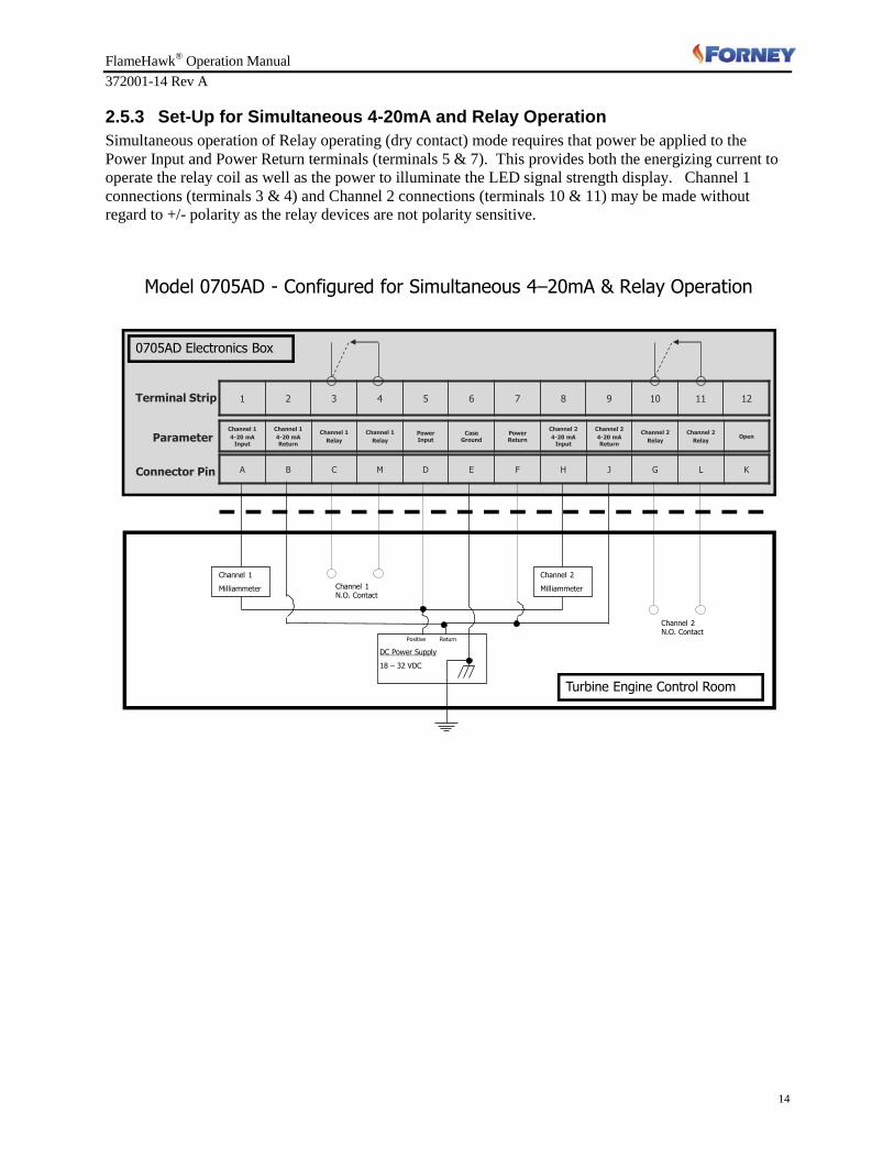
2.5.3 Set-Up for Simultaneous 4-20mA and Relay Operation
Simultaneous operation of Relay operating (dry contact) mode requires that power be applied to the
Power Input and Power Return terminals (terminals 5 & 7). This provides both the energizing current to
operate the relay coil as well as the power to illuminate the LED signal strength display. Channel 1
connections (terminals 3 & 4) and Channel 2 connections (terminals 10 & 11) may be made without
regard to +/- polarity as the relay devices are not polarity sensitive.
DC Power Supply
18 – 32 VDC
Positive Return
Model 0705AD - Configured for Simultaneous 4–20mA & Relay Operation
Channel 1
Milliammeter
Channel 2
Milliammeter
Turbine Engine Control Room
1 2 3 4 5 6 7 8 9 10 11 12
Channel 1
4-20 mA Input
Channel 1
4-20 mA Return
Channel 1
Relay
Channel 1
Relay
Power Input
Case Ground
Power Return
Channel 2
4-20 mA Input
Channel 2
4-20 mA Return
Channel 2
Relay
Channel 2
RelayOpen
A B C M D E F H J G L KConnector Pin
Parameter
Terminal Strip
0705AD Electronics Box
Channel 2 N.O. Contact
Channel 1N.O. Contact
FlameHawk® Operation Manual
372001-14 Rev A
15
Section 3 Maintenance Procedures
There are several optical surfaces for each channel in the 0705AD that should be verified as clean during
regular maintenance.
The surfaces are:
Detector filter window inside electronics enclosure cable fitting *
Combustor end of the fiber optic cable *
Electronics end of the fiber optic cable *
Lens surfaces inside FSA *
The LED viewing window may be cleaned by using a cotton swab or soft cloth soaked in alcohol.
3.1 Recommended Cleaning Materials 1. Cotton swabs, rigid type (6 inch wooden stick)
2. Acetone
3. Isopropyl alcohol, technical grade
4. If available, clean and dry compressed low pressure air or nitrogen gas supply
3.2 Procedure for Electronics End Optics Dirt or contamination does not typically affect this end of the fiber optic cable, but if a visual inspection
reveals a discrepancy, use the following procedure for cleaning:
1. Remove fiber optic cable from electronics enclosure exposing the photodiode optical filter
(.100" diameter dark glass area). If foreign material is found, clean surfaces as described in the
following steps.
2. Soak a clean cotton swab tip in alcohol and wipe filter window gently. Use care not to leave cotton
residue. Use multiple swabs if required to remove all visual signs of contamination (do not re-use
dirty swabs). Blow dry with compressed air or nitrogen or use a new swab to dry the window.
3. Soak another clean swab in alcohol and wipe the end of the fiber optic cable. Blow dry with
compressed air or nitrogen or use a new swab to dry the end of the fiber optic cable.
4. Inspect parts for foreign material and possible damage. Repeat cleaning steps if any foreign material
is found.
5. Mate parts while maintaining cleanliness (Do not touch the end of fiber optic cable).
CAUTION!
DO NOT TRAP FOREIGN OBJECTS INSIDE THE FIBER OPTIC CABLE CONNECTIONS.
FlameHawk® Operation Manual
372001-14 Rev A
16
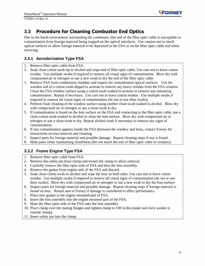
3.3 Procedure for Cleaning Combustor End Optics Due to the harsh environment surrounding the combustor, this end of the fiber optic cable is susceptible to
contamination from foreign material being trapped on the optical interfaces. Use caution not to touch
optical surfaces or allow foreign material to be deposited in the FSA or on the fiber optic cable end when
servicing.
3.3.1 Aeroderivative Type FSA
1. Remove fiber optic cable from FSA.
2. Soak clean cotton swab tip in alcohol and wipe end of fiber optic cable. Use care not to leave cotton
residue. Use multiple swabs if required to remove all visual signs of contamination. Blow dry with
compressed air or nitrogen or use a new swab to dry the end of the fiber optic cable.
3. Remove FSA from combustion chamber and inspect for contaminated optical surfaces. Use the
wooden end of a cotton swab dipped in acetone to remove any heavy residue from the FSA window.
Clean the FSA window surface using a cotton swab soaked in acetone to remove any remaining
contamination. Repeat if necessary. Use care not to leave cotton residue. Use multiple swabs if
required to remove all visual signs of contamination (do not re-use dirty swabs).
4. Perform final cleaning of the window surface using another clean swab soaked in alcohol. Blow dry
with compressed air or nitrogen or use a clean swab to dry.
5. If contamination is found on the lens surface on the FSA end connecting to the fiber optic cable, use a
clean cotton swab soaked in alcohol to clean the lens surface. Blow dry with compressed air or
nitrogen or use a clean swab to dry. Repeat alcohol wash if necessary to remove any signs of
contamination.
6. If any contamination appears inside the FSA (between the window and lens), contact Forney for
instructions on lens removal and cleaning.
7. Inspect parts for foreign material and possible damage. Repeat cleaning steps if any is found.
8. Mate parts while maintaining cleanliness (Do not touch the end of fiber optic cable or window).
3.3.2 Frame Engine Type FSA
1. Remove fiber optic cable from FSA.
2. Remove the safety pin from clamp and loosen the clamp to allow removal.
3. Carefully remove the fiber optic-side of FSA and then the lens assembly.
4. Remove the gasket from engine side of the FSA and discard.
5. Soak clean cotton swab in alcohol and wipe the lens on both sides. Use care not to leave cotton
residue. Use multiple swabs if required to remove all visual signs of contamination (do not re-use
dirty swabs). Blow-dry with compressed air or nitrogen or use a new swab to dry the lens surface.
6. Inspect parts for foreign material and possible damage. Repeat cleaning steps if foreign material is
found on lens. Return unit to Forney if damage is considered to affect performance.
7. Place new gasket in the engine mounted part of FSA.
8. Insert the lens assembly into the engine mounted part of the FSA.
9. Mate the fiber optic-side of the FSA onto the lens assembly.
10. Place clamp over the mating flanges and tighten clamp to 100 in-lbs (make sure lock washer is
outside clamp).
11. Insert safety pin into the clamp.

FlameHawk® Operation Manual
372001-14 Rev A
17
Section 4 System Troubleshooting
The FlameHawk flame detection system can be broken down into three sections. Proper troubleshooting
will need to isolate the problem down to one of these: the FSA, Fiber Optic cable, or Electronics Module.
FSA and Fiber Optic Cable
A visual inspection will determine the condition of the FSA and the Fiber Optic cable.
Is the FSA clean and free of any damage?
Are the ends of the Fiber Optic cable clean?
When light (flashlight or sun light) is transmitted thru one end of the cable, are all 19 fibers
visible at the other end?
If there is contamination on any of the surfaces, clean using the proper procedure.
If there is any damage, replace as necessary.
Electronics Module
Verify that power is applied to the electronics. Check that the Power on LED is lit. If the power on LED
is not lit, unscrew the cover and check voltage on the terminal strip, pins 5 and 7. If voltage is present,
but no LED’s are lit, there is a problem in the electronics module and it should be replaced.
Verify that the LED’s change with signal strength. Remove the fiber optic cable at the housing and
illuminate the Photodiode (flashlight or sunlight). Vary the amount of light and check that the LED’s are
varying with the light input. If not, replace the electronics.
Verify the correct operation of the Relay output and the 4-20ma output. This can be done at the module,
by first disconnecting the wiring and monitoring the proper terminal pins for the appropriate output with a
hand held meter. Check the wiring chart to determine the correct pins.
When monitoring the Relay output, the resistance indicated should vary from 10 ohms (light) to very
high resistance (meg ohms) when darken.
When monitoring the current output, the current should vary from 4ma’s to 20ma’s with a changing light
source from dark to light. If unable to get 20ma’s output with full light input, check the gain pots (user
adjustable) on the top of the electronics module to ensure the signal strength is not being limited by the
gain adjust.
If the electronics module fails to perform as described, it needs to be replaced.

FlameHawk® Operation Manual
372001-14 Rev A
18
Section 5 Warranty
Forney Corporation warrants this product to be free of defective material and workmanship. Forney will
repair or replace this equipment if it is found to be defective upon receipt, but not later than 1 year (12
months) from the date of shipment.
Section 6 Return or Repair Service
Forney Corporation warrants this product to be free of defective material and workmanship. Forney will
repair or replace this equipment if it is found to be defective upon receipt, but not later than 1 year (12
months) days from the date of shipment.
Prior to returning any material to Forney, a Return Material Authorization (RMA) identification number
must be obtained from Forney. Clearly mark the RMA number on all shipping containers and
accompanying documents. Forney accepts only materials submitted in accordance with these RMA
instructions.
To issue an RMA, Forney must have the following information:
List of equipment to be returned by stock number/model number.
Reason for return.
Company name and address of the customer.
Customer's requested mode for return shipping.
Customer's purchase order number for repairs (if applicable).
Customer's requested return date.
Name and address to which Forney is to return-ship and any special container marking information
that may be required.
Name of individual (customer's representative) requesting the RMA.
Any one of the following methods may be used to obtain an RMA:
Phone: 972-458-6100 or 972-458-6142 or 800-356-7740 (24-hour direct line)
Fax: 972-458-6600
Website: http://www.forneycorp.com/return-material-authorizations-rma/
Or e-mail your customer service representative.
FORNEY CORPORATION IS NOT RESPONSIBLE FOR MATERIALS RETURNED WITHOUT
PROPER AUTHORIZATION AND IDENTIFICATION.
Exercise care in packing the materials to be returned. The shipper will be advised of any damage due to
improper packing, and no further action will be taken in connection with this material return until the
shipper provides clearance for further disposition.
FlameHawk® Operation Manual
372001-14 Rev A
19
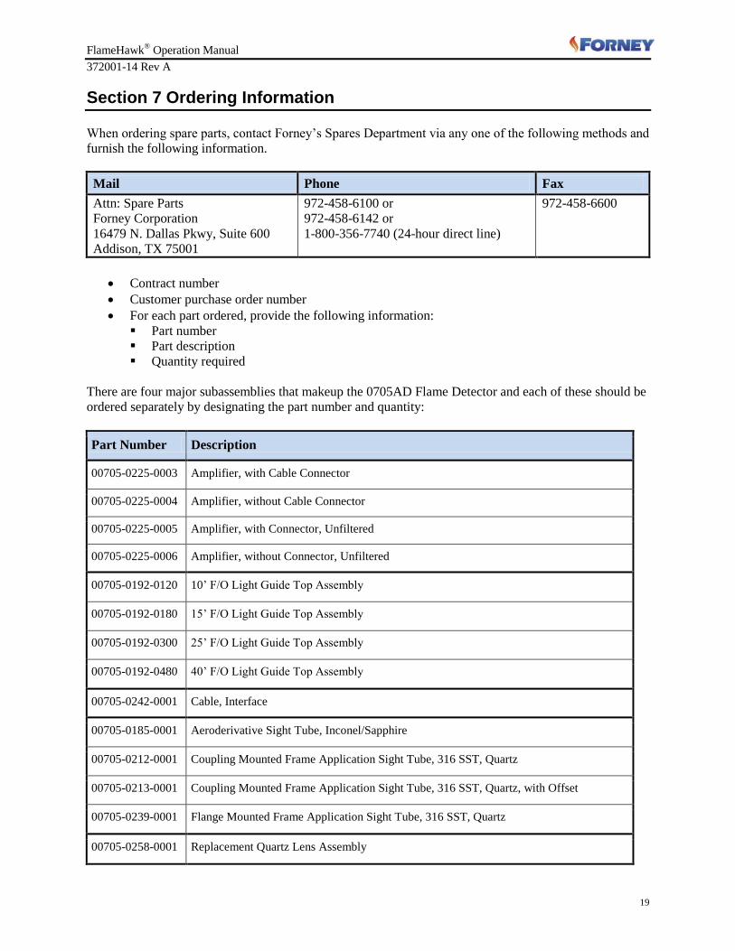
Section 7 Ordering Information
When ordering spare parts, contact Forney’s Spares Department via any one of the following methods and
furnish the following information.
Mail Phone Fax
Attn: Spare Parts
Forney Corporation
16479 N. Dallas Pkwy, Suite 600
Addison, TX 75001
972-458-6100 or
972-458-6142 or
1-800-356-7740 (24-hour direct line)
972-458-6600
Contract number
Customer purchase order number
For each part ordered, provide the following information:
Part number
Part description Quantity required
There are four major subassemblies that makeup the 0705AD Flame Detector and each of these should be
ordered separately by designating the part number and quantity:
Part Number Description
00705-0225-0003 Amplifier, with Cable Connector
00705-0225-0004 Amplifier, without Cable Connector
00705-0225-0005 Amplifier, with Connector, Unfiltered
00705-0225-0006 Amplifier, without Connector, Unfiltered
00705-0192-0120 10’ F/O Light Guide Top Assembly
00705-0192-0180 15’ F/O Light Guide Top Assembly
00705-0192-0300 25’ F/O Light Guide Top Assembly
00705-0192-0480 40’ F/O Light Guide Top Assembly
00705-0242-0001 Cable, Interface
00705-0185-0001 Aeroderivative Sight Tube, Inconel/Sapphire
00705-0212-0001 Coupling Mounted Frame Application Sight Tube, 316 SST, Quartz
00705-0213-0001 Coupling Mounted Frame Application Sight Tube, 316 SST, Quartz, with Offset
00705-0239-0001 Flange Mounted Frame Application Sight Tube, 316 SST, Quartz
00705-0258-0001 Replacement Quartz Lens Assembly