fiber optical sensors in cms s. buontempo on behalf of the fos4hep group cms tracker monitoring...
TRANSCRIPT

Fiber Optical Sensors in CMS
S. Buontempoon behalf of the FOS4HEP Group
CMS Tracker Monitoring meeting, April 6th 2011

Outlook
2
Salvatore (5 min)• FOS technique: Fiber Bragg Grating• FOS in CMS
Zoltan/Noemi (20 min)• 1y FOS measurements in 2010• Bulkhead FOS vs Tracker T (Maki)• Additional UXC T measurements in 2011• FOS data in S4CMS project
Salvatore/Paolo (20 min)• Preliminary R&D results on new FOS
applications• FOS4HEP project

FOS Technique
3
effB n2
Where:neff is the effective refractive index of the fiber,
Λ is the grating pitch and
λB is the reflected Bragg wavelength.
TEMPERATURE CHANGE
Thermal expansion for Termo-optic effect for
STRESS
Elasto-optic effect forDirect Strain for
effn
effn

FOS Technique
4
Temperature Sensitivity ≈10pm/°K
@ λB=1550nm
T
STRAIN AND TEMPERATURE Sensitivity : FBG Spectral Response (Temperature)
FBG SPECTRAL RESPONSE: Temperature Shift

FOS Technique
5
STRAIN AND TEMPERATURE Sensitivity: FBG Spectral Response (Axial Strain)
FBG SPECTRAL RESPONSE: Axial Strain Shift
Strain Sensitivity ≈1pm/με
@ λB=1550nm
ε
For more details: see Prof. Breglio and Prof. Giordano technical seminar in CMShttps://indico.cern.ch/conferenceDisplay.py?confId=56088
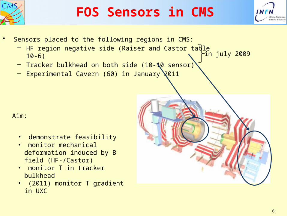
FOS Sensors in CMS
• Sensors placed to the following regions in CMS:– HF region negative side (Raiser and Castor table 10-6)– Tracker bulkhead on both side (10-10 sensor)– Experimental Cavern (60) in January 2011
6
in july 2009
Aim:
• demonstrate feasibility• monitor mechanical
deformation induced by B field (HF-/Castor)
• monitor T in tracker bulkhead• (2011) monitor T gradient in
UXC

Position of BulkHead Temperature sensors
7
Positive side:

Position of BulkHead Temperature sensors
8
Negative side:

Position of CASTOR Platform sensors
9

Position of sensors on the Raiser
10

ZOLTAN TALK
11
• 1y FOS measurements in 2010• Bulkhead FOS vs Tracker T (Maki)• Additional UXC T measurements in 2011
• FOS data in S4CMS project
PRELIMINARY R&D RESULTS ON NEW FOS APPLICATIONS
2011.03.03. 12FOS operation in CMS

13
Preliminary results on new FOS
In 2010 3 lines of R&D activities on FOS techniques have started for HEP applications:
• Low and precise RH in negative T environment (P. Petagna)
• B field (A. Gaddi)
• T and strain in cryogenic conditions (M. Bajko)

Cladding Core
Bragg Grating
Buffer
FBG sensor

Coating Material

By using a functionalized coating material,i.e. mechanically sensible to:B field or Humidity or “Cryo T”

Status of R&D on RH FOS @ PH/DTPaolo Petagna (CERN PH/DT)
•Motivations
•PH/DT test set-up
•Phase I: tip-coated (NFFP) oxide sensors
•Phase II: FBG polyimide sensors
•Phase III: new collaboration agreement

• Almost all miniaturized humidity sensors presently available on the market are electronic sensors (mainly capacitive-based, followed by resistive-based).
• Despite all efforts, these sensors still fail to provide a complete set of favourable characteristics, e.g., good linearity, high sensitivity, low uncertainty, low hysteresis and rapid response time.
• For an application in HEP detectors, one should add to this the sensitivity to electro-magnetic noise pick-up, the suitability for multi-point distributed measurements and the resistance to ionizing radiations.
Motivations
Nowadays – although important requirements on environmental control exist, in particular for Trackers –
there is no miniaturized humidity sensor on the market well suited for HEP detector applications
Paolo Petagna (CERN PH/DT)

PH/DT test set-up
Test section
Thermally controlled liner
Salt solution container (if needed)
External air circulation(dry + saturated air mixer)
Closed loop circulation(salt solution in box)
Chilled mirror
Ranges:0% ≤ RH ≤ 100%
-20 °C ≤ T ≤ +30 °C
Insulated confinement
Paolo Petagna (CERN PH/DT)

Phase I: tip-coated (NFFP) oxide sensors
X axis: 10 µm
Y axis: 10 µm
Fiel
dIn
tens
ity(A
.U.)
X axis: 10 µm Y axis: 10 µm
Surf
ace
peak
she
ight
(µm
)
Optimal SnO2 deposition: sub-wavelength bumps spaced by sub-wavelength distances (wavelength = 1.55 mm)
Build on previous experience of partner institutes (Unisannio, CNR-IMCB, DIBET) on Near-Field Fabry-Perot sensors for chemical applications
Paolo Petagna (CERN PH/DT)

Phase I: tip-coated (NFFP) oxide sensors
• Very good results obtained with two sensors on steady and dynamical behaviour between +20 °C and -20 °C
• Paper submitted to Sensors and Actuators• Patent application filed
BUT EXTREMELY DIFFICULT TO REPRODUCE THE GOOD CONFIGURATION
Paolo Petagna (CERN PH/DT)

Phase I: tip-coated (NFFP) oxide sensors
Help sought in PH/DT (A. Braem / T. Schneider) and TE/VSC (M.Taborelli) to investigate possible way to stabilize the production and obtain a reasonable yield
Two possible techniques have been envisaged and will be tried. Work performed on a “courtesy” base (i.e. depending on available windows), time scale not clear at the moment
Paolo Petagna (CERN PH/DT)

Phase II: FBG + polyimide sensors
Two examples have been recently reported in literature about successful use of polyimide-coated FBG as relative humidity sensors: Kronemberg et al: Relative humidity sensor with optical fiber Bragg gratings, Optics Letters Vol. 27, No. 16 (2002)Yeo et al: Characterisation of a polymer-coated fibre Bragg grating sensor for relative humidity sensing. Sensors and Actuators B, 110 (2005)
Extremely interesting results between +20 C and – 20 C are being obtained in CERN PH/DT test set-up on two commercial FBG polyimide-coated in a non controlled way by the producer (insulation coating)
-20 0 20 40 60 80 100 1204,5
4,6
4,7
4,8
4,9
5,0
5,1
5,2
5,3
5,4
Vn
T1
RH DPM(%)
prova del 24-25-26 gennaio T=20° prova del 27 gennaio e 1-2 febbraio a T=0°C prova del 31 gennaio e 1-2 febbraio a T=0°C prova del 7-8 febbraio a T= -15°C
-20 0 20 40 60 80 100 1204,0
4,2
4,4
4,6
4,8
5,0
prova del 24-25-26 gennaio T=20° prova del 27 gennaio e 1-2 febbraio a T=0°C prova del 31 gennaio e 1-2 febbraio a T=0°C prova del 7-8 febbraio a T= -15°C
Vn
FB
G2
RH DPM(%)
Paolo Petagna (CERN PH/DT)

• Similar sensors can be rather easily produced under controlled conditions by dip coating or by mould coating in a standard UV recoater
• Launched programme to investigate:radiation hardness, effect of coating thickness, effect of polyimide type, reproducibility of the sensor, stability in time
• 10 commercial sensors (few mm polyimide coating) ordered (CMS tracker funds) from an external commercial producer (that can secure at least always the same type of polymide coating). Received at CERN last week. Measurements will start in next days.
• 10 custom sensors ordered (CMS tracker funds) and being produced in different (controlled) thicknesses @ CNR-IMCB. Delivery
• Test production launched in parallel @ CERN (collaboration with TE/MPA)
Phase II: FBG + polyimide sensors
Paolo Petagna (CERN PH/DT)
Phase III: new collaboration agreement
Collaboration agreement for 2011 defined, now under signature process
Programme:LPG multi sensors coated with different oxydes (Sol-Gel deposition) Partners: Unisannio + Uninapoli Federico II (DIBET)
FBG multi sensors coated with fully cured epoxy Partners: CNR Napoli (IMCB) + Uninapoli Federico II (DIBET)
Results expected: Dec 2011
Paolo Petagna (CERN PH/DT)

FOS for B field measurements
Magnetostrictivematerial
FBGHolder
The FBG sensor is glued onto a Magnetostrictive material which changes its shape in function of applied magnetic field. All is placed in a proper holder which produces an initial controlled pre-stress condition.
5 sensors tested
Goal: measure B field at low and high ranges (A. Gaddi)
Preliminary results: Good reproducibility, good linearity in range 500-3500G, small hysteresis and impressive sensitivity (2mV/G)

FOS operation in CMS 27
FOS for Cryo T and strainmeasurements
Goal: measure T and strain in cryogenic conditions (M. Bajko)
The FBG sensor is glued onto a thermostrictive material shrinking up to cryogenic temperatures. Test measurements done @77K and @1.9K
Preliminary results show good reliability and sensitivity up to 1.9K with a single sensor type. Patent option being evaluated.

FOS4HEP project
• idea is to get funding to increase the strengh of the FOS activities at CERN and in involved group sites• First proposal submitted to EU-PEOPLE-MC call in dec 2009. Final score was 76/100, over the threshold of 70/100, but not selected for negotiation phase.• Second proposal edited with help of PNO external consultancy and submitted in EU-PEOPLE-MC call in jan 2011. Result expected by May 2011.

FOS4HEP Participants
3 additional associated partners (Ansaldo SC, Babcock Noell, AMS techn.) not included due to late letter of commitment
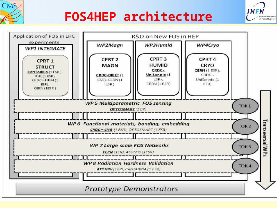
FOS4HEP architecture

FOS4HEP Fellows
14 PhD (3years) and 3 post-Doc (2Years) fellows requested
Summary
2011.03.03. FOS operation in CMS 32
• During 2009 & 2011 ~100 FBG sensors have been installed in CMS
• An automatic DAQ of FBGs has been set up
• FOS system is in 24/7 operation since a year and could follow:- Tracker operation (temperature)- Magnet cyles induced mechanical changes of HF-
• Recently additional 60 T-sensing FOS network has been installed in UXC, monitoring T gradient
• FOS data are integrated into the Sensors4CMS project
• 3 R&D projects were started on the FOS technology for RH, Bfield and Cryogenic applications. Preliminary results look very promising
• FOS4HEP community created and a funding request submitted to EU call.