fiber system solutions - · pdf file · 2012-03-06fiber system solutions ......
TRANSCRIPT

CABLE ASSEMBLIES DISTRIBUTION SYSTEMS CONNECTORS TOOLS ACCESSORIES CABLE
FIBER SYSTEM SOLUTIONSP R O D U C T G U I D E


TABLE OF CONTENTS
TABLE OF CONTENTS
INTRODUCTION 2-3
SYSTEM CONFIGURATIONS 4-5
CABLE ASSEMBLIES 6-17
HYBRID FIBER CABLE ASSEMBLIES 6-9
opticalCON® FIBER OPTIC CABLE ASSEMBLIES 10-11
TAC-4 & TAC-12 CABLE ASSEMBLIES 12-13
ST/SC/LC CABLE ASSEMBLIES 14-17
DISTRIBUTION RACKS & BOXES 18-28
HMD MODULAR DISTRIBUTION RACK 18-19
HMS MODULAR FUSION SPLICE RACK 20-21
HSB FUSION SPLICE BOX 22-23
HDR1 HIGH-DENSITY DISTRIBUTION RACK 24-25
SMPTE FIELD AND STUDIO BOXES 26
HYBRID FIBER BREAKOUT BOXES 27
HMP8-BXX BREAKOUT RACK 28
PANELS 29-33
MODULAR PANELS 29-30
BLANK PANELS 31
FEEDTHROUGH PANELS & CHASSIS 32
CUSTOM PANELS 33
CONNECTORS, TOOLS & ACCESSORIES 34-45
FLOOR BOX PLATES 34
PANEL MOUNT FIBER CONNECTORS 35
LEMO® CONNECTORS 36
SMPTE 304M DUST CAPS, BOOTS & INSTALLATION TOOLS 37
FIBER SYSTEMS ACCESSORIES, PARTS & TOOLS 38-39
MICROSCOPES 40-42
TEST EQUIPMENT 43
FUSION SPLICERS 44-45
CABLE 46-55
9.2MM HYBRID FIBER OPTIC CABLE 46-47
12MM HYBRID FIBER OPTIC CABLE 48
16MM HYBRID FIBER OPTIC CABLE 49
HD CAMERA ELECTRICAL CABLE 50
3-CHANNEL FIBER CABLE 51
SINGLE-MODE OPTICAL FIBER CABLE 52
MULTI-MODE OPTICAL FIBER CABLE 53
SINGLE-MODE TACTICAL OPTICAL FIBER CABLE 54
MULTI-MODE TACTICAL OPTICAL FIBER CABLE 55
PART NUMBER INDEX 56
opticalCON® is a registered trademarks of Neutrik AG. LEMO® is a registered trademark of Interlemo Holding, S.A.

Field-Installable Systems
Modular, Expandable, and Custom Designs
Multiple Connection Choices
Electrically Isolated Connector Mounts
Internal Cable Management Options for Security and Streamlined Breakout
Fusion Splice Options
Premium Connectors and Components
100% Tested and Verified
DISTRIBUTION SYSTEMS
Precision Engineered with Premium Materials
Permanent Install, Portable and Tactical Options
Meets or Exceeds SMPTE Standards
100% Tested and Verified
CABLE
Factory Terminated by Gepco
Precision Machine Polishing
UPC Quality to Achieve -55dB Typical Return Loss
Meets or Exceeds SMPTE Standards
Permanent Install, Portable and Tactical Options
Premium Connectors and Components
100% Tested and Verified
CABLE ASSEMBLIES

FIBER SYSTEM SOLUTIONSCABLE ASSEMBLIES | DISTRIBUTION SYSTEMS | CONNECTORS | TOOLS | ACCESSORIES | CABLE
SMPTE 304M Connectors
Panel Mount Fiber Connectors
Replacement Parts
Cleaning Tools
Microscopes
Test Equipment
Fusion Splicers
BROADCAST & PRO AVIn addition to Gepco Brand cable, cable assemblies, breakout racks, boxes and panels, Gepco offers
the following components and accessories:
As the leading innovator of interconnect technology for the professional broadcast market,
Gepco International® delivers a full line of fiber system solutions for high-definition audio
and video applications. Engineered and manufactured to industry-leading standards,
Gepco® Brand fiber system products bring the optical clarity and reliability required for
high-bandwidth data transmission in television, video production, staging, outdoor
broadcast and professional audio applications. With a complete range of cable
assemblies, panels, components and accessories, Gepco’s optical fiber systems
product line provides a turn-key optical solution.
SYSTEM CONFIGURATIONS
www.gepco.com | 800.966.00694
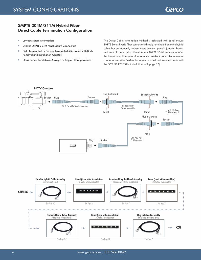
SMPTE 304M/311M Hybrid FiberDirect Cable Termination Configuration
Lowest System Attenuation
Utilizes SMPTE 304M Panel Mount Connectors
Field Terminated or Factory Terminated (if installed with BodyRemoval and Installation Adapter)
Blank Panels Available in Straight or Angled Configurations
Portable Hybrid Cable Assembly
See Page 6-7
See Page 6-7 See Page 7See Page 31
See Page 31 See Page 7 See Page 31
+ +CAMERA
CCU
The Direct Cable termination method is achieved with panel mount
SMPTE 304M hybrid fiber connectors directly terminated onto the hybrid
cable that permanently interconnects between panels, junction boxes,
and control room racks. Panel mount SMPTE 304M connectors offer
the lowest overall insertion-loss at each breakout point. Panel mount
connectors must be field- or factory-terminated and installed onsite with
the DCS.3K.175.72LN installation tool (page 37).
from Camera to PanelPanel (Load with Assemblies)
at Studio or Camera LocationSocket and Plug Bulkhead Assembly
Interconnects Between Blank PanelsPanel (Load with Assemblies)
at Machine Room Location
Portable Hybrid Cable Assemblyfor Patching Between Panels
Panel (Load with Assemblies)at Machine Room Location
Plug Bulkhead AssemblyInterconnect from Panel to CCU

SYSTEM CONFIGURATIONS
www.gepco.com | 800.966.0069 5
SMPTE 304M/311M Hybrid FiberDistribution Rack Configuration
Easy to Field-Install and Terminate
Modular Channels Can Be Reconfigured Onsite
Replaceable Contact Jumpers for Field Serviceability
Uses Cost-Effective, General Purpose Fiberand Electrical Cables
CAMERA
See Page 6-7 See Pages 18, 20, 24 & 28 See Pages 46-55
See Pages 18, 20, 24 & 28 See Page 6-7 See Page 24
CCU
See Page 8
Gepco® Brand distribution racks offer an exceptionally flexible and
modular solution to the field deployment and installation of permanent
installation SMPTE hybrid camera cables. With the Distribution Rack
method, SMPTE 304M connectors are broken out to separate electrical
and optical elements on the back of the distribution rack. These
separate elements can then be readily terminated to fiber and electrical
cable.
In-Line Hybrid Breakout AssemblyInterconnects Back of HDR to CCU
Distribution Rackat Machine Room Location
Portable Hybrid Cable Assemblyfor Patching Between Distribution Racks
Distribution Rackat Machine Room Location
Portable Hybrid Cable Assemblyfrom Camera to Panel
Distribution Rackat Studio or Camera Location
Fiber and Electrical CableInterconnects Between Distribution Racks

CABLE ASSEMBLIES
www.gepco.com | 800.966.00696
SMPTE 304M/311M Hybrid Fiber Cable Assemblies
Portable: Heavy-Duty 12mm Type
Portable: Heavy-Duty 9.2mm Type
PART NUMBER: GHF12B-0-(length)
Gepco® Brand GHF hybrid fiber and copper camera cables are
terminated with SMPTE 304M connectors for high-definition video
camera-to-CCU interconnects.
The GHF assemblies utilize two single-mode fibers for high bit-rate
signal transmission and copper elements for auxiliary and signal
electrical connections. Each fiber is coated with a high-tensile strength
coating for exceptional durability and strength. The copper elements
feature a heat-resistant PE insulation material for dependable
performance in high-temperature environments.
Fiber contacts are machine polished to meet or exceed all SMPTE
standards. With typical UPC performance of -55dB RL, Gepco hybrid
fiber cables achieve exceptional optical clarity to deliver reliable
performance and low transmission loss.
Machine Polished
-55dB Return Loss (Typical)
Portable, Extra-Rugged and Permanent Install Versions
LEMO® Connectors
Heat-Resistant
Meets or Exceeds SMPTE 304M/311M Standards
(One end shown with optionaloverbody boot. Please specifywhen ordering.)
FEATURES & BENEF I TS
Portable: Heavy-Duty 16mm Type
PART NUMBER: GHF16A-0-(length)
Cable TypeHDC160
Connector TypeSMPTE 304M Hybrid Connectors - 1 Plug,1 Socket with Metal Dust Caps
Standard Lengths50’, 100’, 164’, 250’, 328’, 500’, 656’
OptionsLEMO® Connectors
Cable TypeHDC120P
Connector TypeSMPTE 304M Hybrid Connectors - 1 Plug,1 Socket with Metal Dust Caps
Standard Lengths50’, 100’, 164’, 250’, 328’, 500’, 656’
OptionsLEMO® Connectors
Cable TypeHDC920HD
Connector TypeSMPTE 304M Hybrid Connectors - 1 Plug, 1 Socket with Metal Dust Caps
Standard Lengths50’, 100’, 164’, 250’, 328’, 500’, 656’
OptionsLEMO® ConnectorsOverbody Rubber Boot
-OB Add for Overbody Boot Option
PART NUMBER: GHF92HD-0-(length)
LEMO® is a registered trademark of Interlemo Holding, S.A.

CABLE ASSEMBLIES
www.gepco.com | 800.966.0069 7
SMPTE 304M/311M Hybrid Fiber Cable Assemblies
Permanent Installation: Standard In-Line
Permanent Installation: Plug Bulkhead
PART NUMBER: GHF92B-0-(length)
PART NUMBER: GHF92B-0-(length)-PB
Permanent Installation: Socket Bulkhead
PART NUMBER: GHF92B-0-(length)-SB
Permanent Installation: Plug & Socket Bulkhead
PART NUMBER: GHF92B-0-(length)-SPB
Cable TypeHDC920R
Connector TypeSMPTE 304M Hybrid Connectors - 1 Plug,1 Socket with Metal Dust Caps
Standard Lengths50’, 100’, 164’, 250’, 328’, 500’, 656’
OptionsLEMO® Connectors
Cable TypeHDC920R
Connector TypeSMPTE 304M Hybrid Connectors - 1 PlugBulkhead, 1 Socket with Metal Dust Caps
Standard Lengths50’, 100’, 164’, 250’, 328’, 500’, 656’
OptionsLEMO® Connectors
Cable TypeHDC920R
Connector TypeSMPTE 304M Hybrid Connectors - 1 Plug,1 Socket Bulkhead with Metal Dust Caps
Standard Lengths50’, 100’, 164’, 250’, 328’, 500’, 656’
OptionsLEMO® Connectors
Cable TypeHDC920R
Connector TypeSMPTE 304M Hybrid Connectors - 1 PlugBulkhead, 1 Socket Bulkhead with MetalDust Caps
Standard Lengths50’, 100’, 164’, 250’, 328’, 500’, 656’
OptionsLEMO® Connectors
Portable: Extra-Flexible 9.2mm Type
(One end shown with optionaloverbody boot. Please specifywhen ordering.)
Cable TypeHDC920
Connector TypeSMPTE 304M Hybrid Connectors - 1 Plug, 1 Socket with Metal Dust Caps
Standard Lengths50’, 100’, 164’, 250’, 328’, 500’, 656’
OptionsLEMO® ConnectorsOverbody Rubber Boot
-OB Add for Overbody Boot Option
PART NUMBER: GHF92A-0-(length)
LEMO® is a registered trademark of Interlemo Holding, S.A.

CABLE ASSEMBLIES
www.gepco.com | 800.966.00698
ST/SC/LC Optical Breakout
AMP® Electrical Breakout
Machine Polished to -55dB RL (Typical)
Riser Rated 311M Hybrid Cable for PermanentInstallation
Available in Short or Long Cable Lengths
For Interfacing SMPTE Hybrid Devices with the Back Panel ofDistribution Panels or Other Component Level Devices
FEATURES & BENEF I TS
Electrical Breakout Connector Options
A B C E F G H
Fiber Breakout Connector Options
ST SC LC
Hybrid Fiber Connector Options
P PB S SB
GHF92B
Length(First End)
Connector Format(Second End)
Fiber Breakout
- - /
P = Plug
PB = Bulkhead Plug
S = Socket
SB = Bulkhead Socket
ST = ST UPC
SC = SC UPC
LC = LC UPC
DSC = Duplex SC UPC
DLC = Duplex LC UPC
Standard GenderA = 5-Pin AMP® Metal CPC (for Mating with HDR1 & HMP8-Bxx Racks)
B = 8-Pin AMP® CPC
C = 6-Pin AMP® MATE-N-LOK® Cap
D = Blunt
Reverse GenderE = 5-Pin Reverse Gender CPC – In-Line or Panel Mount
F = 8-Pin Reverse Gender CPC – In-Line
G = 8-Pin Reverse Gender CPC – Panel Mount
H = 6-Pin Reverse Gender MATE-N-LOK®
In Feet
(Second End)Electrical Breakout
Hybrid Fiber Breakout: In-Line Cable
Standard Gender Reverse Gender
Gepco® Brand hybrid fiber breakout cables offer an in-line solution for
breaking out SMPTE 304M hybrid fiber connectors to separate optical
and electrical connectors. This solution allows for the interfacing of
SMPTE hybrid camera devices, such as CCUs, directly to the back of a
Gepco HDR1 or HMP8-Bxx distribution rack.
As with all Gepco GHF cables, the breakout series is machine polished
to meet or exceed all SMPTE 304M/311M standards. Terminated with
HDC920R riser rated 9.2mm cable, breakout cables can be used in
most permanent installation environments.
AMP® and MATE-N-LOK® are registered trademarks of Whitaker Corporation.

CABLE ASSEMBLIES
www.gepco.com | 800.966.0069 9
ST/SC/LC Optical Breakout
AMP® Electrical Breakout
Machine Polished to -55dB RL (Typical)
Uses Short Length Fiber and Electrical Elements
For Panel Mounting in Blank Panels or as a Replacementin Hybrid Devices
FEATURES & BENEF I TS
GHFBK
Length(First End)
Connector Format(Second End)
Fiber Breakout
- - /
PB = Bulkhead Plug
SB = Bulkhead Socket
ST = ST UPC
SC = SC UPC
LC = LC UPC
DSC = Duplex SC UPC
DLC = Duplex LC UPC
Standard GenderA = 5-Pin AMP® Metal CPC (for Mating with HDR1 & HMP8-Bxx Racks)
B = 8-Pin AMP® CPC
C = 6-Pin AMP® MATE-N-LOK® Cap
D = Blunt
Reverse GenderE = 5-Pin Reverse Gender CPC – In-line or Panel Mount
F = 8-Pin Reverse Gender CPC – In-line
G = 8-Pin Reverse Gender CPC – Panel Mount
H = 6-Pin Reverse Gender MATE-N-LOK®
In Feet
(Second End)Electrical Breakout
Hybrid Fiber Breakout: Internal Distribution
Electrical Breakout Connector Options
A B C E F G H
Fiber Breakout Connector Options
ST SC LC
Hybrid Fiber Connector Options
PB SB
Standard Gender Reverse Gender
Gepco® Brand hybrid fiber internal distribution cables do not use
conventional hybrid 311M cables and are intended for internal
equipment or panel wiring only. The SMPTE 304M end uses OEM style,
non-cable-mount hybrid connectors and is terminated to insulated
copper wire and individual, simplex breakout fibers. The component
breakout end has ST, SC, or LC optical connectors, while the copper
elements feature AMP® or blunt ends.
As with all Gepco GHF cables, the breakout series is machine polished
to meet or exceed all SMPTE 304M/311M standards.
AMP® and MATE-N-LOK® are registered trademarks of Whitaker Corporation.

CABLE ASSEMBLIES
www.gepco.com | 800.966.006910
Neutrik® opticalCON® Fiber Optic Cable Assemblies
Machine Polished
Two or Four Fiber Channels per Connector
Industry Standard LC Fiber Contacts
Unique Shutter Mechanism Protects Contacts from Damage andContamination
-55dB Return Loss (Typical)
Ruggedized Body
Tactical Optical Fiber Cable
Additional Protection from Included Boot
FEATURES & BENEF I TS
GNO - 0 -
S = Single-Mode 9μm FiberM = Multi-Mode 50μm Fiber
In Feet
Neutrik® opticalCON® cable assemblies by Gepco provide a
streamlined and ruggedized solution for the deployment and
interfacing of optical fiber in commercial and professional AV
applications. The opticalCON connector features a ruggedized body
design, high performance LC fiber contacts, and a unique shutter
mechanism to protect against damage and contamination. Machine
polished and terminated in the USA, opticalCON assemblies by Gepco
provide exceptionally low return-loss, low attenuation, and consistent
end-face geometry. opticalCON assemblies are available in almost any
length and are custom terminated to user specifications.
Overall Specifications
# of Channels: 2 or 4
Connectors: (2) Neutrik® opticalCON®, Nickel (2-Channel) or Ruthenium Finish (2 and 4-Channel) Connector Body with Boot
Cable Type: Tactical, Polyurethane Jacket, 5mm Diameter, Black
Available Lengths: 50', 100', 164', 250', 328', 500', 656', or Custom
Mechanical Performance Specifications
Cable Retention Force: 500N
Lifetime: >1000 Cycles
Insertion/Withdrawal Force: <45N
Operating Temperature: -25°C to +75°C
Minimum Bend Radius: 4cm
Optical Performance Specifications
Type: LC-UPC (Straight Polish)
Fiber Type: 9μm Single-Mode Fiber or 50μm Multi-Mode Fiber
Cable Loss:< 0.5dB/km @ 1310/1550nm (Single-Mode)< 3dB/km @ 850nm (Multi-Mode)< 1dB/km @ 1300nm (Multi-Mode)
Connector Loss: <0.5dB (per Connection)
Connector Back Reflection: -55dB RL (Typical), -45dB RL (Max)
2N = 2-Channel Nickel2R = 2-Channel Ruthenium4R = 4-Channel Ruthenium
Channels/Connector Fiber Length
Also Available with Cable ReelerAdd reeler part number to suffix.
Standard configuration has cable mount connector on both ends. Optionalbulkhead on reel is also available. Add “B” to end of reeler suffix of partnumber.
GT310 GT380 GT520
Neutrik® and opticalCON® are registered trademarks of Neutrik AG.

CABLE ASSEMBLIES
www.gepco.com | 800.966.0069 11
Connector Specifications
Part NumberConnectorDescription Fiber
Shell GroundContact Manufacturer Mating
NO2-4FDW Panel Mount opticalCON®,Hard Nickel Plating
2 — Neutrik® Mates with In-Line 2-Channel Neutrik®
opticalCON® or Standard Duplex LC
NO2-4FDW-R Panel Mount opticalCON®, Ruthenium Plating
2 — Neutrik® Mates with In-Line 2-Channel Neutrik®
opticalCON® or Standard Duplex LC
NO2-4FDW-1 Panel Mount opticalCON®, Hard Nickel Plating
2 1 Neutrik® Mates with In-Line 2-Channel Neutrik®
opticalCON® or Standard Duplex LC
NO2-4FDW-1-R Panel Mount opticalCON®, Ruthenium Plating
2 1 Neutrik® Mates with In-Line 2-Channel Neutrik®
opticalCON® or Standard Duplex LC
NO4FDW-R Panel Mount opticalCON®, Ruthenium Plating
4 — Neutrik® Mates with In-Line 4-Channel Neutrik®
opticalCON® or Standard LC
NA02M-4S75W Coupler opticalCON®, Black
2 x LC-Duplex Multi-Mode PC — Neutrik® Mates with In-Line 2-Channel Neutrik®
opticalCON® or Standard Duplex LC
NA02S-4S75W Coupler opticalCON®, Blue
2 x LC-Duplex Single-Mode PC — Neutrik® Mates with In-Line 2-Channel Neutrik®
opticalCON® or Standard Duplex LC
NA02SA-4S75W Coupler opticalCON®, Green
2 x LC-Duplex Single-Mode APC — Neutrik® Mates with In-Line 2-Channel Neutrik®
opticalCON® or Standard Duplex LC
NA04MW Coupler opticalCON®, Black
4 x Multi-Mode PC — Neutrik® Mates with In-Line 4-Channel Neutrik®
opticalCON® or Standard LC
NA04SW Coupler opticalCON®, Blue
4 x Single-Mode PC — Neutrik® Mates with In-Line 4-Channel Neutrik®
opticalCON® or Standard LC
NA04SAW Coupler opticalCON®- Green
4 x Single-Mode APC — Neutrik® Mates with In-Line 4-Channel Neutrik®
opticalCON® or Standard LC
Neutrik® and opticalCON® are registered trademarks of Neutrik AG.
Neutrik® opticalCON® Panel Mount Connectors & Accessories
Note: Color of coupler indicates the fiber mode included (black: multi-mode, blue: single-mode, green: single-mode APC).
CAS-FOCD opticalCON® Cleaning Kit
• Hand Microscope (400x Magnification) with MicroscopeAdapters for opticalCON® and 2.5mm Ferrules
• opticalCON Cleaning Box (Contains lint-free wipes; opti-mized for opticalCON fiber cleaning.)
• DRY Cleaners for 1.25mm and 2.5mm
• Fiber Optic Cleaning Fluid (Non-flammable)

CABLE ASSEMBLIES
www.gepco.com | 800.966.006912
TAC-4 & TAC-12 Cable Assemblies
Machine Polished
4 or 12 Channels per Connector
Hermaphroditic Design Enables Mating to Cableor Panel Mount Connectors in Either Direction
Extra-Rugged Metal Shell
Dust Cap Included
For Mobile Production Applications
FEATURES & BENEF I TS
GT
Fiber Connector Format
S = Single-Mode
M = Multi-Mode
4 = TAC-4
12 = TAC-12
(Multi-Mode)Core Diameter
(blank) = N/A Single-Mode
/50 = 50μm
/62 = 62.5μm
Length
- 0 -
In Feet
TAC-4 and TAC-12 cable assemblies by Gepco are built for the
transmission of multiple optical fiber elements in hostile and portable
applications. Each connector contains four or 12 elements in an extra-
rugged, hermaphroditic connector shell. The hermaphroditic design
enables cables to be mated to either TAC-4/12 panel connectors or
other TAC-4/12 cables in any direction providing flexibility for cable
link expansion and eliminating cables from being directionally
misdeployed. Machine polished, Gepco® Brand TAC-4/12 cables have
exceptionally low return-loss and attenuation with consistent end-face
geometry. TAC-4/12 cables are available in almost any length and
are custom terminated to user specifications.
Overall Specifications
# of Channels: 4 or 12
Connectors: (2) Amphenol® TAC-4 SMPTE 358M or (2) Amphenol® TAC-12
Cable Type: Tactical, Polyurethane Jacket, 0.220” (TAC-4) or 0.260” (TAC-12) Diameter
Available Lengths: 50', 100', 164', 250', 328', 500', 656', or Custom
Color: Black Cable Jacket, Black Finish (TAC-4) or Gray Finish( TAC-12) Connector Body
Mechanical Performance Specifications
Operating Temperature: -25°C to +75°C
Minimum Bend Radius: 4cm
Optical Performance Specifications
Fiber Type: 8.3μm Single-Mode Fiber, 50μm Multi-Mode Fiber, or 62.5μm Multi-Mode Fiber
Cable Loss:< 0.5dB/km @ 1310/1550nm (Single-Mode)< 3.5dB/km @ 850nm (Multi-Mode)< 1dB/km @ 1300nm (Multi-Mode)
Connector Loss: <0.5dB (per Connection)
Connector Back Reflection: -55dB RL (Typical), -45dB RL (Max)
Amphenol® is a registered trademark of Amphenol Corporation.

CABLE ASSEMBLIES
www.gepco.com | 800.966.0069 13
Connector Specifications
Part Number Connector Format Alignment Sleeve Manufacturer Mating
1098080-A1 Panel Mount Amphenol®
4-Channel Tactical ConnectorUses Fiber Termini, nota Feedthrough Device
Amphenol®Must be terminated and machinepolished with 2 Amphenol® M29504/14Termini, and 2 Amphenol® M29504/15Termini. Termini are sold separately.
FS12A8080X111F Panel Mount Amphenol®
12-Channel Tactical ConnectorUses Fiber Termini, nota Feedthrough Device
Amphenol®Must be terminated and machinepolished with 6 Amphenol® M29504/14Termini, and 6 Amphenol® MIL29B1999CTermini. Termini are sold separately.
1091000-A1 Cable Mount Amphenol®
4-Channel Tactical ConnectorUses Fiber Termini, nota Feedthrough Device
Amphenol®Must be terminated and machine polished with 2 Amphenol® M29504/14 Termini, and 2 Amphenol® M29504/15 Termini. Termini are sold separately.
FS12A1000F1-1F Cable Mount Amphenol®
12-Channel Tactical ConnectorUses Fiber Termini, nota Feedthrough Device
Amphenol®Must be terminated and machinepolished with 6 Amphenol® M29504/14Termini, and 6 Amphenol® MIL29B1999CTermini. Termini are sold separately.
TAC-4 & TAC-12 Connectors
Amphenol® is a registered trademark of Amphenol Corporation.
CABLE ASSEMBLIES
www.gepco.com | 800.966.006914
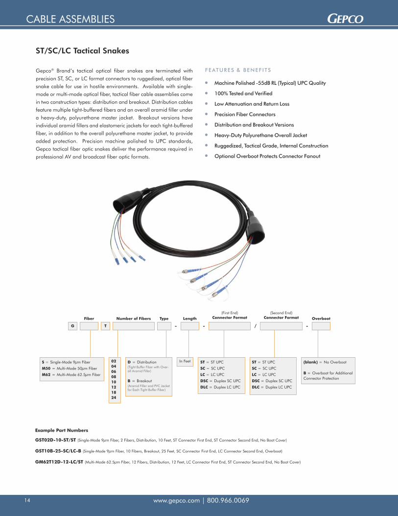
Gepco® Brand’s tactical optical fiber snakes are terminated with
precision ST, SC, or LC format connectors to ruggedized, optical fiber
snake cable for use in hostile environments. Available with single-
mode or multi-mode optical fiber, tactical fiber cable assemblies come
in two construction types: distribution and breakout. Distribution cables
feature multiple tight-buffered fibers and an overall aramid filler under
a heavy-duty, polyurethane master jacket. Breakout versions have
individual aramid fillers and elastomeric jackets for each tight-buffered
fiber, in addition to the overall polyurethane master jacket, to provide
added protection. Precision machine polished to UPC standards,
Gepco tactical fiber optic snakes deliver the performance required in
professional AV and broadcast fiber optic formats.
ST/SC/LC Tactical Snakes
Machine Polished -55dB RL (Typical) UPC Quality
100% Tested and Verified
Low Attenuation and Return Loss
Precision Fiber Connectors
Distribution and Breakout Versions
Heavy-Duty Polyurethane Overall Jacket
Ruggedized, Tactical Grade, Internal Construction
Optional Overboot Protects Connector Fanout
FEATURES & BENEF I TS
G
Fiber
T
Number of Fibers Type Length Overboot(First End)
Connector Format(Second End)
Connector Format
- - -/
S = Single-Mode 9μm Fiber
M50 = Multi-Mode 50μm Fiber
M62 = Multi-Mode 62.5μm Fiber
ST = ST UPC
SC = SC UPC
LC = LC UPC
DSC = Duplex SC UPC
DLC = Duplex LC UPC
ST = ST UPC
SC = SC UPC
LC = LC UPC
DSC = Duplex SC UPC
DLC = Duplex LC UPC
(blank) = No Overboot
B = Overboot for AdditionalConnector Protection
In FeetD = Distribution(Tight Buffer Fiber with Over-all Aramid Filler)
B = Breakout(Aramid Filler and PVC Jacketfor Each Tight Buffer Fiber)
0204060810121824
GST02D-10-ST/ST (Single-Mode 9μm Fiber, 2 Fibers, Distribution, 10 Feet, ST Connector First End, ST Connector Second End, No Boot Cover)
GST10B-25-SC/LC-B (Single-Mode 9μm Fiber, 10 Fibers, Breakout, 25 Feet, SC Connector First End, LC Connector Second End, Overboot)
GM62T12D-12-LC/ST (Multi-Mode 62.5μm Fiber, 12 Fibers, Distribution, 12 Feet, LC Connector First End, ST Connector Second End, No Boot Cover)
Example Part Numbers

CABLE ASSEMBLIES
www.gepco.com | 800.966.0069 15
Gepco® Brand’s optical fiber snakes are terminated with precision ST,
SC, or LC format connectors to plenum or riser rated cable for
permanent installation. Available with single-mode or multi-mode
optical fiber, permanent install cable assemblies come in distribution
and breakout cable constructions. Precision machined polished to UPC
standards, all Gepco fiber optic assemblies deliver the performance
required in professional AV and broadcast fiber optic formats.
Machine Polished -55dB RL (Typical) UPC Quality
100% Tested and Verified
Low Attenuation and Return Loss
Precision Fiber Connectors
Distribution and Breakout Versions
Plenum or Riser Rated for Permanent Install
FEATURES & BENEF I TS
ST/SC/LC Permanent Install Snakes
G
Fiber UL Rating Number of Fibers Type Length(First End)
Connector Format(Second End)
Connector Format
- - /
S = Single-Mode 9μm Fiber
M50 = Multi-Mode 50μm Fiber
M62 = Multi-Mode 62.5μm Fiber
R = Riser Rated
P = Plenum Rated
ST = ST UPC
SC = SC UPC
LC = LC UPC
DSC = Duplex SC UPC
DLC = Duplex LC UPC
ST = ST UPC
SC = SC UPC
LC = LC UPC
DSC = Duplex SC UPC
DLC = Duplex LC UPC
In FeetD = Distribution(Tight Buffer Fiber with Over-all Aramid Filler)
B = Breakout(Aramid Filler and PVC Jacketfor Each Tight Buffer Fiber)
01020406081218243036486072 (Riser Only)
GSR02D-25-ST/ST (Single-Mode 9μm Fiber, Riser Rated, 2 Fibers, Distribution, 25 Feet, ST Connector First End, ST Connector Second End)
GSP08B-50-SC/LC (Single-Mode 9μm Fiber, Plenum Rated, 8 Fibers, Breakout, 50 Feet, SC Connector First End, LC Connector Second End)
GM62R12D-10-LC/ST (Multi-Mode 62.5μm Fiber, Riser Rated, 12 Fibers, Distribution, 10 Feet, LC Connector First End, ST Connector Second End)
Example Part Numbers

CABLE ASSEMBLIES
www.gepco.com | 800.966.006916
Gepco® Brand’s optical fiber assemblies are terminated with precision
ST, SC, or LC format connectors to plenum or riser rated cable for
permanent installation. Available with single-mode or multi-mode
optical fiber, simplex cable assemblies are precision machined polished
to UPC standards. All Gepco fiber optic assemblies deliver the
performance required in professional AV and broadcast fiber optic
formats.
Machine Polished -55dB RL (Typical) UPC Quality
100% Tested and Verified
Low Attenuation and Return Loss
Precision Fiber Connectors
Plenum or Riser Rated for Permanent Install
FEATURES & BENEF I TS
ST/SC/LC Simplex Cables
GSR01S-25-ST/ST (Single-Mode 9μm Fiber, Riser Rated, 25 Feet, ST Connector First End, ST Connector Second End)
GSP01S-50-SC/LC (Single-Mode 9μm Fiber, Plenum Rated, 50 Feet, SC Connector First End, LC Connector Second End)
GM62R01S-10-LC/ST (Multi-Mode 62.5μm Fiber, Riser Rated, 10 Feet, LC Connector First End, ST Connector Second End)
Example Part Numbers
G
Fiber UL Rating
01S
Length(First End)
Connector Format(Second End)
Connector Format
- - /
S = Single-Mode 9μm Fiber
M50 = Multi-Mode 50μm Fiber
M62 = Multi-Mode 62.5μm Fiber
R = Riser Rated
P = Plenum Rated
ST = ST UPC
SC = SC UPC
LC = LC UPC
DSC = Duplex SC UPC
DLC = Duplex LC UPC
ST = ST UPC
SC = SC UPC
LC = LC UPC
DSC = Duplex SC UPC
DLC = Duplex LC UPC
In Feet

CABLE ASSEMBLIES
www.gepco.com | 800.966.0069 17
Gepco® Brand’s optical fiber assemblies are terminated with precision
ST, SC, or LC format connectors to plenum or riser rated cable for
permanent installation. Available with single-mode or multi-mode
optical fiber, duplex cable assemblies are precision machined polished
to UPC standards. All Gepco fiber optic assemblies deliver the
performance required in professional AV and broadcast fiber optic
formats.
Machine Polished -55dB RL (Typical) UPC Quality
100% Tested and Verified
Low Attenuation and Return Loss
Precision Fiber Connectors
Plenum or Riser Rated for Permanent Install
FEATURES & BENEF I TS
ST/SC/LC Duplex Cables
GSR02Z-25-ST/ST (Single-Mode 9μm Fiber, Riser Rated, 25 Feet, ST Connector First End, ST Connector Second End)
GSP02Z-50-SC/LC (Single-Mode 9μm Fiber, Plenum Rated, 50 Feet, SC Connector First End, LC Connector Second End)
GM62R02Z-10-LC/ST (Multi-Mode 62.5μm Fiber, Riser Rated, 10 Feet, LC Connector First End, ST Connector Second End)
Example Part Numbers
G
Fiber UL Rating
02Z
Length(First End)
Connector Format(Second End)
Connector Format
- - /
S = Single-Mode 9μm Fiber
M50 = Multi-Mode 50μm Fiber
M62 = Multi-Mode 62.5μm Fiber
R = Riser Rated
P = Plenum Rated
ST = ST UPC
SC = SC UPC
LC = LC UPC
DSC = Duplex SC UPC
DLC = Duplex LC UPC
ST = ST UPC
SC = SC UPC
LC = LC UPC
DSC = Duplex SC UPC
DLC = Duplex LC UPC
In Feet

DISTRIBUTION RACKS & BOXES
www.gepco.com | 800.966.006918
HMD Modular Distribution Rack
Internal SC and Electrical Breakout Distribution
Internal Cable Management for Security and StreamlinedBreakout
Field Installable
Mating Fiber Can Be Terminated with Polish, Quick Cleave, or Fusion Splice SC Connectors
Can Be Spliced with Any Type of Fusion Splicer(with SC Splice Connector Option)
Electrically Isolated Connector Mounts
Rear Cable Ports for Maximum Cable Strain Relief
Easy to Expand, 6-Channel Frame
Connector Modules for SMPTE 304M and opticalCON® FormatConnectors
FEATURES & BENEF I TSThe new Gepco® Brand HMD Modular Distribution Rack provides a
field terminatable solution for the deployment of hybrid fiber
connectors in an expandable chassis system. With internal cable
management and component SC plus electrical element breakout, the
HMD allows for all electrical and fiber termination to occur within the
chassis, streamlining and protecting the cable breakout.
Unique to the HMD, the SC breakout at each position allows for the
hybrid connectors to be replaced, serviced or expanded via a quick
disconnect. The SC termination of the interconnecting cable between
HMD racks can be field terminated with epoxy and polish, quick
cleave, or fusion splice SC fiber connectors. To facilitate cable
management of SC fusion spliced connectors, each breakout position
also features an additional splice holder clip within the HMD chassis.
For flexibility in cable options, the HMD features configurable rear
cable ports (six plus two) that accommodate a wide range of cable
types and combinations. The HMD can be terminated to a variety of
combinations of HDC920 9.2mm hybrid fiber, discrete electrical and
fiber cables, or up to two HDC3R 3-channel hybrid cables.
All HMD configurations come with six electrically isolated connector
positions for expandability. Each position can ordered or expanded
with SMPTE 304M plug, SMPTE 304M socket, or Neutrik® opticalCON®
format connectors, with future connector modules available as they are
released.
Expandable, electrically isolated connector modulesTerminate matingcable with SC
connector options
Rear cable ports Internal SC andelectrical breakout
Neutrik® and opticalCON® are registered trademarks of Neutrik AG.

DISTRIBUTION RACKS & BOXES
www.gepco.com | 800.966.0069 19
Ordering & Product Specifications
HMD
Front Panel Type # of Channels Connector Type
-
2A = Angled 2RU2 = Flat 2RU
123456
P = SMPTE PlugS = SMPTE Socket
NS = Neutrik® opticalCON®: Single-Mode
NM = Neutrik® opticalCON®: Multi-Mode
Optional Accessories
Part Number Description Compatibility Notes
GSKIT-HDP221P Gland Seal Kit for HDP221P Plenum Electrical Cable Kit for One Strain Relief
GSKIT-BKFBR-S Gland Seal Kit for Breakout Fiber: 2-, 4- or 6-Channel Riseror Plenum, 8-Channel Plenum Kit for One Strain Relief
GSKIT-BKFBR-L Gland Seal Kit for Breakout Fiber: 8-Channel Riser, 12-Channel Riser or Plenum Kit for One Strain Relief
GSKIT-HDC3R Gland Seal Kit for HDC3R 3-Channel Hybrid Cable Kit for One Strain Relief
HMD-EKIT-P SMPTE Plug Expansion Module Kit For HMD Frames
HMD-EKIT-S SMPTE Socket Expansion Module Kit For HMD Frames
HMD-EKIT-NS Neutrik® opticalCON® Single-Mode Expansion Module Kit For HMD Frames
HMD-EKIT-NM Neutrik® opticalCON® Multi-Mode Expansion Module Kit For HMD Frames
Mechanical Specifications
Dimensions: 2RU-3.5" H x 19" W x 5.75" D
Optical Connector Specifications:LEMO® SMPTE 304M or Neutrik® opticalCON® : 1 per Channel (2 Fibers)SC-PC Duplex Breakout: 1 per Channel (2 Fibers)-55dB Typical RL, 0.4dB Max IL Connector End
Electrical Breakout:6-Position AMP® MATE-N-LOK® Connector
Rear Panel Cable Management:(6) Ports for Electrical/Hybrid Fiber Cable(2) Ports for Fiber/3-Channel Hybrid Fiber Cable
Included Accessories:Mating AMP® MATE-N-LOK® Connector(s)Gland Seals for HDP221, HDC920 or HDC920RGland Seals for 2- to 4-Channel Distribution FiberGland Seals for 6- to 12-Channel Distribution Fiber
Neutrik® and opticalCON® are registered trademarks of Neutrik AG. AMP® and MATE-N-LOK® are registered trademarks of Whitaker Corporation.
DISTRIBUTION RACKS & BOXES
www.gepco.com | 800.966.006920
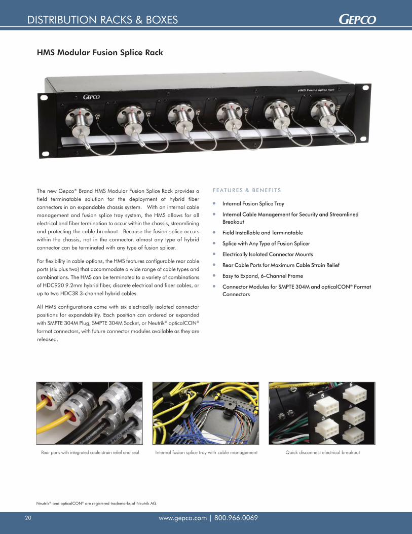
HMS Modular Fusion Splice Rack
Internal Fusion Splice Tray
Internal Cable Management for Security and StreamlinedBreakout
Field Installable and Terminatable
Splice with Any Type of Fusion Splicer
Electrically Isolated Connector Mounts
Rear Cable Ports for Maximum Cable Strain Relief
Easy to Expand, 6-Channel Frame
Connector Modules for SMPTE 304M and opticalCON® FormatConnectors
FEATURES & BENEF I TSThe new Gepco® Brand HMS Modular Fusion Splice Rack provides a
field terminatable solution for the deployment of hybrid fiber
connectors in an expandable chassis system. With an internal cable
management and fusion splice tray system, the HMS allows for all
electrical and fiber termination to occur within the chassis, streamlining
and protecting the cable breakout. Because the fusion splice occurs
within the chassis, not in the connector, almost any type of hybrid
connector can be terminated with any type of fusion splicer.
For flexibility in cable options, the HMS features configurable rear cable
ports (six plus two) that accommodate a wide range of cable types and
combinations. The HMS can be terminated to a variety of combinations
of HDC920 9.2mm hybrid fiber, discrete electrical and fiber cables, or
up to two HDC3R 3-channel hybrid cables.
All HMS configurations come with six electrically isolated connector
positions for expandability. Each position can ordered or expanded
with SMPTE 304M Plug, SMPTE 304M Socket, or Neutrik® opticalCON®
format connectors, with future connector modules available as they are
released.
Rear ports with integrated cable strain relief and seal Internal fusion splice tray with cable management Quick disconnect electrical breakout
Neutrik® and opticalCON® are registered trademarks of Neutrik AG.

DISTRIBUTION RACKS & BOXES
www.gepco.com | 800.966.0069 21
HMS
Front Panel Type # of Channels Connector Type
-
2A = Angled 2RU2 = Flat 2RU
123456
P = SMPTE Plug
S = SMPTE Socket
NS = Neutrik® opticalCON®: Single-Mode
NM = Neutrik® opticalCON®: Multi-Mode
Ordering & Product Specifications
Mechanical Specifications
Dimensions: 2RU-3.5" H x 19" W x 6.5" D
Optical Connector Specifications:LEMO® SMPTE 304M or Neutrik® opticalCON® Fiber Contacts: 2 per Channel-55dB Typical RL, 0.2dB Max IL Connector EndOpposite End Blunt for Fusion Splicing
Electrical Breakout:6-Position AMP® MATE-N-LOK® Connector
Rear Panel Cable Management:(6) Ports for Electrical/Hybrid Fiber Cable(2) Ports for Fiber/3-Channel Hybrid Fiber Cable
Included Accessories:Mating AMP® MATE-N-LOK® Connector(s)Fusion Splice Heat ShrinkGland Seals for HDP221, HDC920 or HDC920RGland Seals for 2- to 4-Channel Distribution FiberGland Seals for 6- to 12-Channel Distribution Fiber
Optional Accessories
Part Number Description Compatibility Notes
GSKIT-HDP221P Gland Seal Kit for HDP221P Plenum Electrical Cable Kit for One Strain Relief
GSKIT-BKFBR-S Gland Seal Kit for Breakout Fiber: 2-, 4- or 6-Channel Riser orPlenum, 8-Channel Plenum Kit for One Strain Relief
GSKIT-BKFBR-L Gland Seal Kit for Breakout Fiber: 8-Channel Riser, 12-ChannelRiser or Plenum Kit for One Strain Relief
GSKIT-HDC3R Gland Seal Kit for HDC3R 3-Channel Hybrid Cable Kit for One Strain Relief
HMS-EKIT-P SMPTE Plug Expansion Module Kit For HMS Frames
HMS-EKIT-S SMPTE Socket Expansion Module Kit For HMS Frames
HMS-EKIT-NS Neutrik® opticalCON® Single-Mode Expansion Module Kit For HMS Frames
HMS-EKIT-NM Neutrik® opticalCON® Multi-Mode Expansion Module Kit For HMS Frames
Neutrik® and opticalCON® are registered trademarks of Neutrik AG. AMP® and MATE-N-LOK® are registered trademarks of Whitaker Corporation.

DISTRIBUTION RACKS & BOXES
www.gepco.com | 800.966.006922
Rugged, twist-and-lock, 5-pin electrical andST fiber breakout
Configurable ports for multiplecable-type compatibility
Custom fusion splice tray with cable management
Optional rack panel and base
HSB Fusion Splice Box
Custom Fusion Splice Tray for Hybrid Cables
Internal Cable Management for Security and StreamlinedBreakout
Configurable Cable Ports for Strain Relief of Multiple CableFormats
Field Installable and Terminatable
Can Be Spliced with Any Type of Fusion Splicer
Twist-and-Lock, Metal-Body, External Connectors forExceptional Durability
Expandable up to Four Channels
FEATURES & BENEF I TSThe new Gepco® Brand HSB Fusion Splice Box provides a field
terminatable solution for the deployment of hybrid fiber cable in a
compact chassis. Specifically designed for hybrid camera applications,
the HSB features configurable cable ports and a custom fusion splice
tray specifically designed for use with 9.2mm SMPTE hybrid cable,
discrete electrical and fiber cables, or the HDC3R 3-channel hybrid
cable.
Internally, the optical fibers terminate within the HSB’s custom fusion
splice tray—using the included splice heat shrink and cable
management accessories—while the electrical elements terminate with
quick-disconnect, 6-position, plastic AMP® connectors. For the external
component breakout, the HSB series utilizes metal, twist-and-lock ST
and 5-pin connectors for a secure and reliable exterior mating
interface.
To permanently install the HSB splice box, an optional base kit can be
added to mount the HSB splice box to a wall or floor, or it can be rack
mounted with an optional rack panel. For up to eight channels for
splicing, two HSBs can be mounted in a single 3RU rack panel.
AMP® is a registered trademark of Whitaker Corporation.

DISTRIBUTION RACKS & BOXES
www.gepco.com | 800.966.0069 23
Optional Accessories
Part Number Description Compatibility Notes
GSKIT-HDP221P Gland Seal Kit for HDP221P Plenum Electrical Cable Kit for One Strain Relief
GSKIT-BKFBR-S Gland Seal Kit for Breakout Fiber: 2-, 4- or 6-Channel Riser or Plenum, 8-Channel Plenum Kit for One Strain Relief
GSKIT-BKFBR-L Gland Seal Kit for Breakout Fiber: 8-Channel Riser, 12-Channel Riser or Plenum Kit for One Strain Relief
GSKIT-HDC3R Gland Seal Kit for HDC3R 3-Channel Hybrid Cable Kit for One Strain Relief
HSB-EKIT Expansion Splice Kit for 1 Hybrid Channel For HSB Splice Boxes
HSB-BASE Base Feet for Floor or Wall Mounting For HSB Splice Boxes
HSB-RP1 2RU Panel for Rack Mounting One HSB Box For HSB Splice Boxes
HSB-RP2 3RU Panel for Rack Mounting Two HSB Boxes For HSB Splice Boxes
GHFBK-3-PB/STA Plug Pigtail Breakout Cable with ST and AMP® 5-Pin For HMP8 Panels and HSB Boxes
GHFBK-3-SB/STA Socket Pigtail Breakout Cable with ST and AMP® 5-Pin For HMP8 Panels and HSB Boxes
HSB
# of Channels
1234
AMP® and MATE-N-LOK® are registered trademarks of Whitaker Corporation.
Ordering & Product Specifications
Mechanical Specifications
Dimensions: 11.5” L x 5.5” W x 2.5” H
Optical Connector Specifications:ST Female (2 per Channel)-55dB Typical RL, 0.2dB Max IL Connector EndOpposite End Blunt for Fusion Splicing
Electrical Breakout:6-Position AMP® MATE-N-LOK® Connector (Internal)5-Position AMP® CPC (External)
Panel Cable Management Ports:(1-4) Ports for Electrical/Hybrid Fiber Cable(1) Port for Fiber/3-Channel Hybrid Fiber Cable
Included Accessories:Mating AMP® MATE-N-LOK® Connector(s)Fusion Splice Heat ShrinkGland Seal(s) for HDP221, HDC920 or HDC920RGland Seal for 2- to 4-Channel Distribution FiberGland Seal for 6- to 12-Channel Distribution Fiber

DISTRIBUTION RACKS & BOXES
www.gepco.com | 800.966.006924
HDR1 High-Density, Hybrid Fiber Distribution Rack
High-Density 1RU Chassis
External ST Fiber and Metal Circular Electrical Breakout
Electrically Isolated Connector Mounts
Designation Strip for Each Position
Ideal for Machine Room Patching
Field Installable and Terminatable
Expandable 6-Channel Frame
Connector Modules for SMPTE 304M and opticalCON® FormatConnectors
FEATURES & BENEF I TSThe new Gepco® Brand HDR1 High-Density Distribution Rack delivers
a hybrid fiber breakout or patching solution in a compact 1RU frame.
With the highest density available, the HDR1 can deliver up to six
positions in a 1RU space, or up to 12 positions in a 2RU space (with
two HDR1 units). Commonly used for machine room patching of
multiple camera positions to available CCU control units, the HDR1
provides a streamlined cross-connect or general purpose hybrid
breakout system.
Each hybrid connector position of the HDR1 externally breaks out to
separate fiber and electrical connectors on the rear of the panel. To
provide rugged external connector interfacing, the HDR1 utilizes ST
fiber and metal circular, 5-pin electrical connectors. These connector
breakout formats can easily be terminated onsite without the need for
specialized hybrid connector tooling.
All positions on the new HDR1 are completely electrically isolated by
nonconductive connector mounts on the front, and the hybrid
connector shells are wired to isolated pins on the rear of the chassis.
For custom user-labeling and identification, each position features a
designation strip. Available with SMPTE 304M plug, SMPTE 304M
socket, or Neutrik® opticalCON® format connectors, every
configuration comes loaded in a standard frame that can be expanded
up to six channels with pre-terminated connector modules.
Rear panel with fiber and electrical component breakoutElectrically isolated connector modules
Neutrik® and opticalCON® are registered trademarks of Neutrik AG.

DISTRIBUTION RACKS & BOXES
www.gepco.com | 800.966.0069 25
Optional Accessories
Part Number Description Compatibility Notes
HDR1-EKIT-P SMPTE Plug Expansion Module Kit For HDR1 Frames
HDR1-EKIT-S SMPTE Socket Expansion Module Kit For HDR1 Frames
HDR1-EKIT-NS Neutrik® opticalCON® Single-Mode Expansion Module Kit For HDR1 Frames
HDR1-EKIT-NM Neutrik® opticalCON® Multi-Mode Expansion Module Kit For HDR1 Frames
Mechanical Specifications
Dimensions: 1RU-1.75" H x 19" W x 3" D
Optical Connector Specifications:LEMO® SMPTE 304M: 1 per Channel (2 Fibers)ST Breakout: 2 per Channel (2 Fibers)-55dB Typical RL, 0.4dB Max IL
Electrical Breakout:5-Pin Metal AMP® CPC
Included Accessories:Mating AMP® 5-Pin CPC Connectors
HDR1
# of Channels Connector Type
-
123456
P = SMPTE Plug
S = SMPTE Socket
NS = Neutrik® opticalCON®: Single-Mode
NM = Neutrik® opticalCON®: Multi-Mode
Ordering & Product Specifications
Neutrik® and opticalCON® are registered trademarks of Neutrik AG. AMP® is a registered trademark of Whitaker Corporation.

DISTRIBUTION RACKS & BOXES
www.gepco.com | 800.966.006926
HDB
# of Channels Connector Gender Enclosure Type
- -
12
3 3M - (Ported for SingleHDC3R 3-Way Cable)
P = SMPTE Plug
S = SMPTE Socket
Termination
W = Weather-Proof Stainless Steel
I = Indoor Painted Steel
(blank) = Internal SC Breakout
FS = Internal Fusion Splice
SMPTE Field and Studio Boxes
Field Box for SMPTE 304M Interconnects
Weather-Proof Stainless Steel or Indoor-Rated Steel Versions
Hinged Top Panel with Clamps
Internal SC Breakout or Fusion Splice Tray
Configurable Cord Grips/Cable Management
Distributes Hybrid Connector Over Fiber and CopperDistribution, SMPTE 311M or 3-Channel Hybrid Cables
Available in 1-, 2- or 3-Channel Configurations
FEATURES & BENEF I TS
Mechanical Specifications
Dimensions:8" L x 6" W x 4" D Standard 1, 2 or 3ch and 1ch Fusion Splice Models: Stainless Steel8" L x 6" W x 3.5" D Standard 1, 2 or 3ch and 1ch Fusion Splice Models: Indoor Painted Steel10" L x 8" W x 4" D Fusion Splice 2 and 3ch Models: Stainless Steel or Indoor Painted Steel
0.75" Flanged Base with Mounting Holes
Optical Connector Specifications:SMPTE 304M LEMO® Stainless Steel Connector (Plug or Socket)SMPTE 304M Dust Cap with Weather Seal and Coated LanyardSC-PC Single-Mode Breakout (Internal Breakout Version Only - 2 per Channel)
Fiber Contacts: 2 per Channel -55dB Typical RL, 0.4dB Max IL (SMPTE and SC Contacts)
Electrical Breakout Specifications:6-Pin AMP® MATE-N-LOK® Cap: 3 Pins, 2 Sockets
Cord Grips: 1-, 2- or 3-Channel Models:Electrical Only/Hybrid Fiber Ports - (1 per Channel):Cable OD 0.310" - 0.380": HDP221, HDC920 or HDC920R
Fiber Ports - (1 per Channel):Cable OD 0.130" - 0.190", 2-Strand DistributionCable OD 0.250" - 0.310", 2-Strand BreakoutNote: Secondary Cord Grip Can Be Replaced with Included Weather-Proof Hole Plug
Cord Grips: 3M Models for HDC3R 3-Way Cable:Single Cord Grip for 3-Way Hybrid CableCable OD 0.500" - 0.630"
Standard Model
Internal SC Fiber and AMP® Electrical Breakout
Field-Installed Cables Can Be Terminated by Polishing, Field Term Gel, or Fusion SplicingSC Connectors
Standard Model Includes Splice Holder for SC Spliced Connector
Fusion Splice Model
Internal Fusion Splice Tray for Full Figure-8 Cable Management
AMP® Electrical Breakout Panel
Used for Splicing SMPTE Connector Directly to Field-Installed Cable Without SC Breakout
Top Cable Ports
LEMO® is a trademark of Interlemo Holding, S.A. AMP® and MATE-N-LOK® are registered trademarks of Whitaker Corporation.
Included Accessories
Gland Seals for 9.2mm Hybrid/HDP221 Electrical Cable, 2-Strand Distribution Fiber, and2-Strand Breakout Fiber (1, 2 and 3ch Models Only)
Gland Seals for HDC3R 3-Way Fiber Cable (3M Models Only)
Mating AMP® Connectors for Electrical Breakout
Optional Accessories
GSKIT-HDP221P - Gland Seal Kit or HDP221P Plenum Electrical Cable: Kit for OneStrain Relief
FSC-SC - Factory Polished Connector with 12" Tight Buffer 900μm SM Fiber for FusionSplicing
318-191-627 - Field Term SC Connector for 900μm - Quick Cleave with IM Gel
DISTRIBUTION RACKS & BOXES
www.gepco.com | 800.966.0069 27
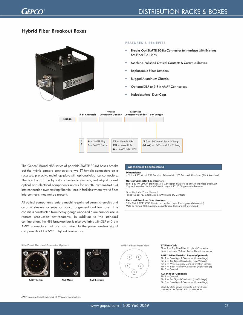
The Gepco® Brand HBB series of portable SMPTE 304M boxes breaks
out the hybrid camera connector to two ST female connectors on a
recessed, protective metal top-plate with optional electrical connectors.
The breakout of the hybrid connector to discrete, industry-standard
optical and electrical components allows for an HD camera-to-CCU
interconnection over existing fiber tie-lines in facilities where hybrid fiber
interconnects may not be present.
All optical components feature machine-polished ceramic ferrules and
ceramic sleeves for superior optical alignment and low loss. The
chassis is constructed from heavy-gauge anodized aluminum for use in
remote production environments. In addition to the standard
configuration, the HBB breakout box is also available with XLR or 5-pin
AMP® connectors that are hard wired to the power and/or signal
components of the SMPTE hybrid connectors.
Breaks Out SMPTE 304M Connector to Interface with ExistingSM Fiber Tie-Lines
Machine-Polished Optical Contacts & Ceramic Sleeves
Replaceable Fiber Jumpers
Rugged Aluminum Chassis
Optional XLR or 5-Pin AMP® Connectors
Includes Metal Dust Caps
Hybrid Fiber Breakout Boxes
1 2
4
5
3
ST Fiber CodeFiber A = Top Blue Fiber in Hybrid ConnectorFiber B = Lower Yellow Fiber in Hybrid Connector
AMP® 5-Pin Electrical Pinout (Optional)Pin 1 = Gray Signal Conductor (Low-Voltage)Pin 2 = Red Signal Conductor (Low-Voltage)Pin 3 = White Auxiliary Conductor (High-Voltage)Pin 4 = Black Auxiliary Conductor (High-Voltage)Pin 5 = Ground
XLR Pinout (Optional)Pin 1 = GroundPin 2 = Red Signal Conductor (Low-Voltage)Pin 3 = Gray Signal Conductor (Low-Voltage)
Black & white power elements in hybrid fiber connector are floated with no connector.
AMP® 5-Pin: Front ViewSide Panel Electrical Connector Options
AMP® 5-Pin XLR Male XLR Female
FEATURES & BENEF I TS
HBB90
# of ChannelsHybrid
Connector GenderElectrical
Connector Gender
13
P = SMPTE Plug
S = SMPTE Socket
Box Length
XF = Female XLRs
XM = Male XLRs
A = AMP® 5-Pin CPC
/4.5 = 1-Channel Box 4.5” Long
(blank) = 3-Channel Box 9” Long
Mechanical Specifications
Dimensions:4.5" L x 5.25" W x 4.5" D Standard 1ch Model: 1/8” Extruded Aluminum (Black Anodized)
Optical Connector Specifications:SMPTE 304M LEMO® Stainless Steel Connector (Plug or Socket) with Stainless Steel DustCap with Weather Seal and Coated Lanyard SC-PC Single-Mode Breakout
Fiber Contacts: 2 per Channel -55dB Typical RL, 0.4dB Max IL (SMPTE and SC Contacts)
Electrical Breakout Specifications:5-Pin Metal AMP® CPC (Breaks out auxiliary, signal, and ground elements.)Male or Female XLR (Auxiliary elements from fiber are not terminated.)
AMP® is a registered trademark of Whitaker Corporation.

DISTRIBUTION RACKS & BOXES
www.gepco.com | 800.966.006928
HMP8-Bxx SMPTE 304M Breakout Rack
Loaded and Terminated HMP8 Breakout Rack
SMPTE 304M Plug or Socket to 5-Pin/ST Breakout
Angled Front Panel
Electrically Isolated Connectors
Available with One to Eight Breakout Positions
Expandable
FEATURES & APPL ICAT IONS
Specifications
Frame Dimensions: 2RU-3.5" H x 19" W x 3" D
Optical SpecificationsTwo Fiber Contacts per Channel-55dB Typical RL 0.4dB Max IL (Both Ends in Closed Loop)
Front Panel1 LEMO® SMPTE 304M Connector per ChannelStainless Steel Connector Body with Stainless Steel Dust Cap
Rear PanelElectrical Breakout: 1 AMP® 5-Pin Connector per ChannelOptical Breakout: 2 ST Connectors per Channel
HMP8
# of Channels Connector Gender
-
Top View Rear View
12 35678
P = SMPTE Plug
S = SMPTE Socket
B
The Gepco® Brand HMP8-Bxx is a completely terminated and loaded version of the HMP8 Modular Panel (opposite page). Positions are loaded
with factory terminated SMPTE 304M connectors, which break out to 5-pin/ST connectors that are mounted in the rear connector panel
attachment. Choose from one to eight loaded positions in socket or plug gender configurations. Unused positions are filled with blank
modules that can later be removed and expanded with additional SMPTE 304M breakout cable modules.
Optional Accessories
Part Number Description Compatibility Notes
HMP8-EKIT-P LEMO® SMPTE 304M Plug Expansion Kit For HMP8 Frames
HMP8-EKIT-S LEMO® SMPTE 304M Socket Expansion Kit For HMP8 Frames
LEMO® is a trademark of Interlemo Holding, S.A. AMP® is a registered trademark of Whitaker Corporation.

PANELS
www.gepco.com | 800.966.0069 29
HMP8 Modular Hybrid Fiber and Triax Panel
Neutrik® and opticalCON® are registered trademarks of Neutrik AG. ADC® and ProAx® are registered trademarks of ADC Telecommunication, Inc.
The Gepco® Brand HMP8 modular panel system provides a completely configurable and electrically isolated connector-mounting solution in an
angled 2RU rack unit system. With the HMP8 frame, up to eight triax and/or hybrid fiber connectors can be mounted in various combinations to
customize the interface panel for each system. Available in five types, the nonconductive plastic HMP8 modules provide electrical isolation between
connectors and are available in SMPTE 304M, Neutrik® opticalCON®, ADC® ProAx® and blank versions. In addition, optional rear cable
management breakout or lacing bar panels can be attached to the HMP8 frame to provide additional security and strain relief for hybrid fiber
pigtail breakout cables.
Specifications
HMP8-F Dimensions
2RU-3.5" H x 19" W x 1.31" D
HMP8-RP Dimensions
2.1" H x 17.1" W x 3" D
HMP8-LB Dimensions
1.1" H x 17.1" W x 5" D
HMP8-RPRear Panel for (8) AMP® 5-Pin and (16) ST Feedthrough Connectors
HMP8-LBLacing Bar
HMP8-F8-Position Modular Panel
HMP8-APADC® ProAx®
Plug Mount
HMP8-NNeutrik®
opticalCON® Mount
HMP8-SSMPTE Universal
Mount
HMP8-AJADC® ProAx®
Jack Mount
HMP8-BBlank Module
Custom Configurable 8-Position Frame
Angled Front Panel Reduces Cable Bend Radius
Electrically Isolated Connectors
All-Metal Frame
Nonconductive Plastic Modules
Optional Rear Connector or Lacing BarPanel Attachments
ADC® ProAx®, SMPTE 304M, andNeutrik® opticalCON® Mounts
FEATURES & APPL ICAT IONS
Ideal for Use With Bulkhead or Breakout Hybrid Fiber Cable Assemblies:
Bulkhead Hybrid (See page 7) In-Line Breakout (See page 8) Internal Breakout (See page 9)

PANELS
www.gepco.com | 800.966.006930
Modular Isolation Panel System
Gepco® Brand’s modular isolation panel system is designed to provide flexibility and expansion capabilities for the mounting of hybrid fiber and
triax connectors in a 19-inch rack format. The all-metal HMPF frame provides seven positions for the connector module mounts and is angled to
reduce the bend radius and clearance required for the interfacing cables. Available in four types, the nonconductive plastic HMP modules provide
electrical isolation between connectors and are available in SMPTE 304M, Kings® Tri-Loc®, Neutrik® opticalCON® and blank versions. In addition,
optional rear cable management breakout or lacing bar panels can be attached to the HMPF frame to provide additional security and strain relief
for hybrid fiber pigtail breakout cables.
Custom Configurable 7-Position Frame
Angled Front Reduces Cable Bend Radius
Electrically Isolates Connectors
All-Metal Frame
Nonconductive Plastic Modules
Optional Rear Connector or Lacing BarPanel Attachments
SMPTE 304M, Kings® Tri-Loc® and Neutrik®
opticalCON® Connector Mounts
FEATURES & BENEF I TS
Ideal for Use With Bulkhead or Breakout Hybrid Fiber Cable Assemblies:
Bulkhead Hybrid (See page 7) In-Line Breakout (See page 8) Internal Breakout (See page 9)
HMPRRear Panel for (7) AMP® 5-Pin and (14) ST Feedthrough Connectors
HMP8-LBLacing Bar
HMPF7-Position Modular Panel
HMP-TKings® Triax
Mount
HMP-NNeutrik®
opticalCON® Mount
HMP-SSMPTE Universal
Mount
HMP-BBlank Module
Specifications
HMPF Dimensions
2RU-3.5" H x 19" W
HMPR Dimensions
1.36" H x 17.1" W x 3.7" D
HMP8-LB Dimensions
1.1" H x 71.1" W x 5" D
Module Dimensions
2" H x 2" W
Kings® and Tri-Loc® are registered trademarks of Kings Electronics Company, Inc. Neutrik® and opticalCON® are registered trademarks of Neutrik AG.

PANELS
www.gepco.com | 800.966.0069 31
Gepco® Brand HBP panels offer a pre-engineered solution for the
mounting of SMPTE 304M hybrid fiber connectors in a 19” rack.
Available in 1RU, 2RU, and angled 2RU versions, all panels feature
Gepco’s unique Universal Punch Mount that allows for plug or socket
connectors to be mounted in any position. Each position also features
a hole for mounting the dust cap lanyard eyelets directly to the panel.
The HBP panels are used in the Direct Cable Termination method (see
page 4 for system configuration details). When using HBP panels with
pre-terminated cable assemblies, the connector body of the cable
assembly can be removed, allowing for the assembly to be passed
through the panel hole punch from the rear and reassembled from the
front.
Angled 2RU Panel
Hybrid Fiber Blank Panels
1RU, 2U, or Angled 2RU Versions
Universal Punch Mount Accommodates Plug or SocketConnectors (Does not accommodate PEW Connectors)
Works with LEMO® Brand Connectors
Additional Hole for Dust Cap Lanyard Mounting
Can Be Loaded with Pre-terminated Cable Assemblies
PART NUMBER: HBPA-*U * Designates Number of Holes (1-6)
FEATURES & BENEF I TS
Note: Custom panels are also available. Please contact Gepco for details.
Straight 2RU PanelPART NUMBER: HBP2-*U * Designates Number of Holes (1-6)
Straight 1RU PanelPART NUMBER: HBP1-*U * Designates Number of Holes (1-6)
Ideal for Use With Bulkhead or Breakout Hybrid Fiber Cable Assemblies:
Bulkhead Hybrid (See page 7) In-Line Breakout (See page 8) Internal Breakout (See page 9)
LEMO® is a registered trademark of Interlemo Holding, S.A.

PANELS
www.gepco.com | 800.966.006932
Feedthrough Panels & Chassis
Specifications
Part Number Panel Type Connector Format Number of Positions Dimensions Additional Features
FP1-xxSTFC1-xxST
FlatChassis
ST Feedthrough 6, 8, 10, or 121RU: 1.75"H x 19"W1RU: 1.75"H x 19"W x 3"D
Zirconia Sleeve, Metal Dust Caps
FP1-xxSCFC1-xxSC
FlatChassis
SC Feedthrough 6, 8, 10, or 121RU: 1.75"H x 19"W1RU: 1.75"H x 19"W x 3"D
Zirconia Sleeve, Spring LoadedShutter
FP1-xxSCDFC1-xxSCD
FlatChassis
SC Duplex Feedthrough 4, 6, or 81RU: 1.75"H x 19"W1RU: 1.75"H x 19"W x 3"D
Zirconia Sleeve
FP1-xxLCFC1-xxLC
FlatChassis
LC Feedthrough 6, 8, 10, or 121RU: 1.75"H x 19"W1RU: 1.75"H x 19"W x 3"D
Zirconia Sleeve
FP1-xxLCDFC1-xxLCD
FlatChassis
LC Duplex Feedthrough 6, 8, 10, or 121RU: 1.75"H x 19"W1RU: 1.75"H x 19"W x 3"D
Zirconia Sleeve, Spring LoadedShutter
Gepco® Brand’s series of feedthrough panels provides a convenient,
pre-engineered solution for bulkhead interfacing of general-purpose
ST, SC or LC optical fiber formats. Utilizing premium-grade, zirconia
sleeve connectors, Gepco feedthrough panels deliver precision optical
alignment and low insertion loss. Available in two configurations, the
flanged panel series provides extra rigidity to minimize panel flexing,
while the chassis series provides a complete rear enclosure for cable
management.
Precision, Zirconia Sleeve Connectors
Available with ST, SC, or LC Format Connectors
Flanged Panel Series for Extra Rigidity
Chassis Series for Integrated Cable Management
Black Anodized and Engraved
FEATURES & BENEF I TS

PANELS
www.gepco.com | 800.966.0069 33
Custom Panels
In addition to pre-engineered panels, chassis, and distribution systems,
Gepco can design and manufacture panels to custom installation
requirements. Panels can be fabricated from aluminum, steel, or
stainless steel in a variety of colors, paint, or anodized finishes.
Connector punches can be made for a complete range of broadcast
and professional AV connector formats. Engraving, filling, and custom
silk-screening options finish off the complete customized interface
solution for your venue or facility.
Completely Customized Panels
Aluminum, Steel or Stainless Steel
Wide Range of Connector Punches Available
Engraved, Filled or Silk Screened
Loaded with Connectors or Blank
Flat, Flanged, or Chassis Configurations
FEATURES & BENEF I TS
Connector FormatsST FeedthroughSC FeedthroughLC FeedthroughSMPTE 304M Plug BulkheadSMPTE 304M Socket BulkheadNeutrik® opticalCON®
TAC-4/12BNCTriaxAudio Connectors
MaterialsAluminumSteelStainless Steel
FinishesAnodizedPaintedPowder CoatedEngravedSilk Screened
Neutrik® and opticalCON® are registered trademarks of Neutrik AG.

CONNECTORS, TOOLS & ACCESSORIES
www.gepco.com | 800.966.006934
Floor Box Plates
Connector Plates for Mystery™, FSR™ and Ace™ Floor Boxes
SMPTE 304M Universal Punch Fits Plug or Socket Connectors(Not compatible with PEW Type)
Black Anodized Aluminum
Custom Configurations Also Available
FEATURES & BENEF I TS
Specifications
Part Number Floor Box Type Compatibility Number of SMPTE 304M Universal Punches
FBP-MD-S Mystery™ Duoline 1
FBP-MM-S1 Mystery™ Moduline 1
FBP-MM-S2 Mystery™ Moduline 2
FBP-FL-S1 FSR™ FL-2000 1
FBP-FL-S2 FSR™ FL-2000 2
FBP-FL-S3 FSR™ FL-2000 3
FBP-FL-S4 FSR™ FL-2000 4
FBP-FL-S5 FSR™ FL-2000 5
FBP-FL-S6 FSR™ FL-2000 6
FBP-FL-S7 FSR™ FL-2000 7
FBP-FL-S8 FSR™ FL-2000 8
FBP-GP1-S1 1 Gang for FSR™ or Ace™ 1
FBP-GP2-S1 2 Gang for FSR™ or Ace™ 1
FBP-GP2-S2 2 Gang for FSR™ or Ace™ 2
FBP-GP3-S1 3 Gang for FSR™ or Ace™ 1
FBP-GP3-S2 3 Gang for FSR™ or Ace™ 2
FBP-GP3-S3 3 Gang for FSR™ or Ace™ 3
FBP-GP4-S1 4 Gang for FSR™ or Ace™ 1
FBP-GP4-S2 4 Gang for FSR™ or Ace™ 2
FBP-GP4-S3 4 Gang for FSR™ or Ace™ 3
FBP-GP4-S4 4 Gang for FSR™ or Ace™ 4
FBP-GP6-S1 6 Gang for FSR™ or Ace™ 1
FBP-GP6-S2 6 Gang for FSR™ or Ace™ 2
FBP-GP6-S3 6 Gang for FSR™ or Ace™ 3
FBP-GP6-S4 6 Gang for FSR™ or Ace™ 4
FBP-GP6-S5 6 Gang for FSR™ or Ace™ 5
FBP-GP6-S6 6 Gang for FSR™ or Ace™ 6
FBP-MD-S
FBP-GP2-S2 FBP-MM-S2 FBP-MM-S1
Mystery™ is a trademark of Mystery Electronics, LLC. FSR™ is a trademark of FSR Incorporated. Ace™ is a trademark of Ace Backstage Co., Inc.

CONNECTORS, TOOLS & ACCESSORIES
www.gepco.com | 800.966.0069 35
Panel Mount Fiber Connectors
Feedthrough, panel mount, fiber connectors provide precision
alignment and mating between two cable mount connectors. With the
exception of the TAC-4/12 types, these connectors do not contain a
ceramic ferrule or optical fiber elements. Terminated cables must be
mated to both sides of the panel mount feedthrough to complete the
interconnect.
General purpose, industry standard ST, SC, and LC formats are
available in multiple configurations, including shuttered versions for the
SC and LC formats. Neutrik® opticalCON® panel mount connectors
use a LC duplex format feedthrough that is shuttered for contaminant
protection. As with the standard LC feedthroughs, opticalCON
connectors require a duplex LC connector to complete the interconnect
and panel wiring.
The TAC-4/12 panel mount connectors utilize fiber termini that must
be bonded to the fiber and machine polished. The hermaphroditic
design of the TAC-4/12 format permits the panel mount versions to be
mated to either end of a TAC4/12 cable assembly.
Panel Mount Configurations
ST, SC, LC, and General-Purpose Formats
Weather-Tight Shuttered Versions Available
Zirconia Sleeves
Precision Optical Alignment
Neutrik® opticalCON®
TAC-4/12 Connectors
FEATURES & BENEF I TS
Connector Format Part Number Alignment Sleeve Manufacturer Mating
ST Feedthrough 216-101-E Zirconia (Ceramic) Senko® Couples Two Male, Cable Mount STs
SC Feedthrough 277-101-1N 222-101-1N (with Flange & Mounting Holes)
Zirconia (Ceramic) Senko® Couples Two Male, Cable Mount SCs
SC Feedthrough withExternal Shutter
227-101-1E 222-101-1E (with Flange & Mounting Holes)
Zirconia (Ceramic) Senko® Couples Two Male, Cable Mount SCs
SC Feedthrough - Duplex227-201-1N222-201-1N (with Flange & Mounting Holes)
Zirconia (Ceramic) Senko® Couples Four Male, Cable Mount SCs
LC Feedthrough 999-111 Zirconia (Ceramic) Senko® Couples Two Male, Cable Mount LCs
LC Feedthrough - Duplex (SC Footprint)
999-411999-311 (with Flange & Mounting Holes)
Zirconia (Ceramic) Senko® Couples Four Male, Cable Mount LCs
LC Feedthrough - Duplex (SC Footprint) withExternal Shutter
999-411-1E999-311-1E (with Flange & Mounting Holes)
Zirconia (Ceramic) Senko® Couples Four Male, Cable Mount LCs
opticalCON®, Hard Nickel Plating
NO2-4FDWNO2-4FDW-1 (with Shell Ground Contact)
Zirconia (Ceramic) Neutrik® Mates with In-Line 2-Channel Neutrik®
opticalCON® or Standard Duplex LC
opticalCON®, Ruthenium Plating
NO2-4FDW-RNO2-4FDW-1-R (with Shell Ground Contact)
Zirconia (Ceramic) Neutrik® Mates with In-Line 2-Channel Neutrik®
opticalCON® or Standard Duplex LC
opticalCON®, Ruthenium Plating
NO4FDW-R Zirconia (Ceramic) Neutrik® Mates with In-Line 4-Channel Neutrik®
opticalCON® or Standard LC
Amphenol® 4-ChannelTactical Connector
1098080-A1Uses Fiber Termini, nota Feedthrough Device
Amphenol®Must be terminated and machinepolished with 2 Amphenol® M29504/14Termini, and 2 Amphenol® M29504/15Termini. Termini are sold separately.
Amphenol® 12-ChannelTactical Connector
FS12A8080X111F Uses Fiber Termini, nota Feedthrough Device
Amphenol®Must be terminated and machinepolished with 6 Amphenol® M29504/14Termini, and 6 Amphenol® MIL29B1999CTermini. Termini are sold separately.
Neutrik® and opticalCON® are registered trademarks of Neutrik AG. Amphenol® is a registered trademark of Amphenol Corporation.

CONNECTORS, TOOLS & ACCESSORIES
www.gepco.com | 800.966.006936
LEMO® Hybrid Fiber SMPTE 304M Connectors
LEMO® 3K series connectors, the original and industry standard in
SMPTE 304M connectors, deliver the performance and dependability
required in demanding broadcast and production applications. These
latest generation of LEMO 3K connectors feature an integrated cable
grip collet, braid crimp, and strength member anchor for exceptional
pull, bend, and strain relief. In addition, all exterior components are
now machined from stainless steel for superior hardness and corrosion
resistance. The F2 optical contacts deliver consistent end-face geometry
and long-term mating life.
Original and Industry Standard HDTV Camera Connector
Stainless Steel Exterior Components
Integrated Collet, Crimp, and Anchor Strain Relief System
Precision F2 Optical Contacts
In-Line Cable Mount, Chassis Cable Mount, and BreakoutVersions
Meets or Exceeds SMPTE 304M Standards
FEATURES & BENEF I TS
Part Number Configuration Gender Cable Type Notes
FUW.3K.93C.TLMC96 Cable Mount Plug 9.2mm Heavy-Duty Strain Relief & Stainless Steel Body
PUW.3K.93C.TLCC96 Cable Mount Socket 9.2mm Heavy-Duty Strain Relief & Stainless Steel Body
FUW.3K.93C.TLMC12 Cable Mount Plug 12mm Heavy-Duty 12mm Stainless Steel Body
PUW.3K.93C.TLCC12 Cable Mount Socket 12mm Heavy-Duty 12mm Stainless Steel Body
FMW.3K.93C.TLMC96Z Panel Mount Plug 9.2mm Square Flange with Mounting Holes, Stainless Steel
PBW.3K.93C.TLCC96Z Panel Mount Socket 9.2mm Square Flange with Mounting Holes
PEW.3K.93C.TLCC96Z Panel Mount Socket 9.2mm Round with Locking Ring, Stainless Steel
FXW.3K.93C.TLM Panel Mount Plug Breakout Not for Cable Mount, OEM Devices Only, Stainless Steel
EDW.3K.93C.TLC Panel Mount Socket Breakout Not for Cable Mount, OEM Devices Only, Stainless Steel
PSS.F2.BB2.LCE30 F2 Fiber Contact Plug 9.2mm or 12mmFor Use with any LEMO® SMPTE 304M Plug: Requires 2 per Connector
FFS.F2.BB2.LCE30 F2 Fiber Contact Socket 9.2mm or 12mmFor Use with any LEMO® SMPTE 304M Socket: Requires2 per Connector
LEMO® is a registered trademark of Interlemo Holding, S.A.

CONNECTORS, TOOLS & ACCESSORIES
www.gepco.com | 800.966.0069 37
SMPTE 304M Dust Caps, Boots & Installation Tools
These Gepco® Brand and LEMO® Brand accessories provide additional
protection, weather resistance, and flex-relief to SMPTE 304M series hybrid
fiber connectors. The stainless steel dust caps protect the end face and
optical fiber contacts from exterior contamination when the connector is
unmated and not in use. They feature a heavy-gauge, coated lanyard
chain to virtually eliminate breakage and fraying. Overbody boots provide
exceptional full-connector protection, while the standard boot option
provides additional flex relief to the connector and cable.
Also available is the DCS series cable pulling adapter and the
3k.93C.U0729 extended shell and midpiece. The adapter replaces the
connector body during cable installation, allowing for a pre-terminated
hybrid fiber cable to be pulled in a permanent installation application,
while the extended shell extends the body of the connector for fusion
splicing.
Stainless Steel Dust Caps with Heavy-Duty Lanyard
Overbody Boots for Full Connector Protection
Standard Flex-Relief Boots
Cable Pulling Adapter for Installing Pre-Terminated Cables
Extended Shell and Midpiece for Fusion Splice Process
FEATURES & BENEF I TS
Part Number Description Compatibility
HPDC Stainless Steel Dust Cap SMPTE 304M Cable Mount Plug
HSDC Stainless Steel Dust Cap SMPTE 304M Cable Mount Socket
HPDC-PM Stainless Steel Dust Cap SMPTE 304M Panel Mount Plug
HSDC-PM Stainless Steel Dust Cap SMPTE 304M Panel Mount Socket
GMF.3K.085.EANZ Full Body Plug Boot LEMO® 9.2mm FUW Cable Mount Plug Connector
GMP.3K.085.EANZ Full Body Socket Boot LEMO® 9.2mm PUW Cable Mount Socket Connector
GMF.3K.085.U0729 Full Body Plug BootLEMO® 9.2mm FUW Cable Mount Plug Connectorwith Fusion Splice Option
GMP.3K.085.U0279 Full Body Socket BootLEMO® 9.2mm PUW Cable Mount Socket Connectorwith Fusion Splice Option
GMA.3B.090.DN Bend Relief Boot 9.2mmLEMO® 9.2mm FGW, PHW, FMW, PBW, or PEW Connectors(Not compatible with Standard FUW and PUW Connectors)
GMA.4B.011.DN Bend Relief Boot 12mmLEMO® 12mm FGW or PHW Connectors(Not compatible with Standard FUW and PUW Connectors)
DCS.3K.175.72LN Cable Pulling SlugTemporarily Replaces Body of LEMO® FUW, PUW, FMW, PBW, orPEW Connectors for Pulling Cable in a Permanent Installation
3K.93C.U0729Extended Shell and Midpiece for Fusion Splice Process
Extends Body of LEMO® 9.2mm FUW, PUW, PBW, FMW and PEWConnectors for Fusion Splicing (Note: Only compatible LEMO®
Connectors that contain “C96” in the part number)
LEMO® is a registered trademark of Interlemo Holding, S.A.

CONNECTORS, TOOLS & ACCESSORIES
www.gepco.com | 800.966.006938
Fiber Systems Accessories, Parts & Tools
Replacement Parts & Tools Part Number Description
HDR-JMP-F2/SC HDR-JMP-F2/STHDR-JMP-F2/BLUNT
Replacement F2 to SC Internal JumperReplacement F2 to ST Internal JumperReplacement F2 to Blunt Internal Jumper
FSC-F2Fusion Splice F2 Contact KitIncludes 2 Pre-terminated F2 Contacts, 2 Splice Sleeves and 2 Alignment Devices (LEMO® FSS.F2.BA2.U0729)
FSC-SC Fusion Splice SC Contact KitIncludes 2 Pre-terminated SC Contacts and 2 Splice Sleeves
AMP-66182-1 Replacement AMP® Pins
AMP-305183 AMP® Pin Extraction Tool
AMP-208719-1 AMP® 5-Pin Panel Mount Connector
Cable Mount Electrical Connectors Part Number Description
AMP-208718-1 AMP® 5-Pin Cable Mount CPC Plug
AMP-208945-5 AMP® CPC Metal Shell with Clamp
AMP-66183-1 AMP® CPC Socket (for 26 - 20 AWG Wire)
AMP-66181-1 AMP® CPC Socket (for 18 - 16 AWG Wire)
Reelers Manufacturer Features/Options
Hannay®
Material: Rugged Steel and Aluminum FrameSize: Standard, Large, and Extra-Large SizesTypes: Stackable or Light-Weight with Optional Divider Panels for FanoutsAdditional Options: Heavy-Duty Locking Casters
AMP® is a registered trademark of Whitaker Corporation. Hannay® is a registered trademark of Hannay Reels, Inc.

CONNECTORS, TOOLS & ACCESSORIES
www.gepco.com | 800.966.0069 39
Fiber Systems Accessories, Parts & Tools
Alignment Removal Tools Part Number Description
DCS.F2.035.PN Dual-Ended Tool for Plug-End Alignment Sleeve Removalof SMPTE 304M Connectors
DCS.91.F23.LASingle-Ended Tool for Plug-End Alignment Sleeve Removalof SMPTE 304M Connectors with Cotton Swab Reservoir
Cleaning Swabs & Tools Part Number Description Quantity per Package
WST.KI.125.34Premoistened Cotton Swabs - Pack of 2(One Dry, One Wet) for SMPTE 304M, ST, SC, or LC Contacts
2
HFCS Cotton Swabs (Not Premoistened)for SMPTE 304M, ST, SC, or LC Contacts
100
HFCDDouble Ended (2.0/2.5mm) Optical ConnectorCleaner, Stick-Type for Cleaning Ferrule-End Faces of SMPTE 304M Connectors and Adapters
100
SCK-SC-250 Cleaning Tool for Female Panel Mount ST, SCor Other 2.5mm Fiber Contacts
1 (525+ Cleaning Uses)
SCK-SC-125 Cleaning Tool for Female Panel Mount LC or Other1.25mm Fiber Contacts
1 (525+ Cleaning Uses)

CONNECTORS, TOOLS & ACCESSORIES
www.gepco.com | 800.966.006940
USB Microscope with Analytical Software
Specifications
Part Number Display Size Magnification PC Interface Resolution Software Included Accessories Included Tips Included
FS-USB None (Uses PC) 450x - 1500x USB 0.5μm Analytical Software Lightweight Rugged Carry CaseSMPTE F2 Universal Tip,SMPTE F2 Plug Tip,2.5mm ST/SC/FC Tip
Additional Tips
Connector Format Part Number Description Included with Scope Kit
ST/SC/FC FSTIP-ST/SC/FC 2.5mm ST, SC, or FC In-Line YesST/SC/FC APC FSTIP-ST/SC/FC-APC 2.5mm ST-APC, SC-APC, or FC-APC In-Line No - OptionalST Panel FSTIP-STPM ST Panel Mount (Does Not Require Connector Removal) No - OptionalSC Panel FSTIP-SCPM SC Panel Mount (Does Not Require Connector Removal) No - OptionalSC-APC Panel FSTIP-SCPM-APC SC-APC Panel Mount (Does Not Require Connector Removal) No - OptionalFC Panel FSTIP-FCPM FC Panel Mount (Does Not Require Connector Removal) No - OptionalFC-APC Panel FSTIP-FCPM-APC FC-APC Panel Mount (Does Not Require Connector Removal) No - OptionalLC FSTIP-LC 1.25mm LC In-Line No - OptionalLC-APC FSTIP-LC-APC 1.25mm LC-APC In-Line No - OptionalLC Panel FSTIP-LCPM LC Panel Mount (Does Not Require Connector Removal) No - OptionalSMPTE F2 Universal FSTIP-F2U SMPTE F2 Universal Plug or Socket YesSMPTE F2 Plug FSTIP-F2P SMPTE F2 Plug (Does Not Require Connector Removal) Yes
USB Format Probe
Bench-Top Testing and Cataloging
450x – 1500x Variable Magnification
0.5μm Resolution
Analytical PC Application Included
Contamination and Scratch Analysis Against UserDefined Criteria
Includes Tips for SMPTE F2 and ST/SC/FC Contacts
Optional Tips Also Available
FEATURES & BENEF I TS

CONNECTORS, TOOLS & ACCESSORIES
www.gepco.com | 800.966.0069 41
Portable Microscope with USB Output
Specifications
Part Number Display Size Magnification PC Interface Resolution Software Included Accessories Included Tips Included
FS-200 3.5" TFT 200x USB 1μ m (Viewable to 0.5μm) Image Capture Soft Cary Bag, AC ChargerSMPTE F2 Universal Tip,SMPTE F2 Plug Tip,2.5mm ST/SC/FC Tip
Rugged Chassis and Probe
Portable
Rechargeable Battery
3.5” TFT Display
200x Magnification
USB Port with Image Capture Software
Includes Tips for SMPTE F2 and ST/SC/FC Contacts
Optional Tips Also Available
FEATURES & BENEF I TS
Additional Tips
Connector Format Part Number Description Included with Scope Kit
ST/SC/FC FSTIP-ST/SC/FC 2.5mm ST, SC, or FC In-Line YesST/SC/FC APC FSTIP-ST/SC/FC-APC 2.5mm ST-APC, SC-APC, or FC-APC In-Line No - OptionalST Panel FSTIP-STPM ST Panel Mount (Does Not Require Connector Removal) No - OptionalSC Panel FSTIP-SCPM SC Panel Mount (Does Not Require Connector Removal) No - OptionalSC-APC Panel FSTIP-SCPM-APC SC-APC Panel Mount (Does Not Require Connector Removal) No - OptionalFC Panel FSTIP-FCPM FC Panel Mount (Does Not Require Connector Removal) No - OptionalFC-APC Panel FSTIP-FCPM-APC FC-APC Panel Mount (Does Not Require Connector Removal) No - OptionalLC FSTIP-LC 1.25mm LC In-Line No - OptionalLC-APC FSTIP-LC-APC 1.25mm LC-APC In-Line No - OptionalLC Panel FSTIP-LCPM LC Panel Mount (Does Not Require Connector Removal) No - OptionalSMPTE F2 Universal FSTIP-F2U SMPTE F2 Universal Plug or Socket YesSMPTE F2 Plug FSTIP-F2P SMPTE F2 Plug (Does Not Require Connector Removal) Yes

CONNECTORS, TOOLS & ACCESSORIES
www.gepco.com | 800.966.006942
LEMO® Microscope Kit
Rugged Carrying Case
Portable
Rechargeable Battery and Charger
3.5” TFT-LCD Display
Foldable Monitor Set with Adjustable Viewing Angle
One-Hand Operation
Fast, Easy Focus
FEATURES & BENEF I TS
Specifications
Part Number Description
WST.CI.100.1AMicroscope Kit - Includes Scope, LCD Display, Positioner for F2 SMPTE 304M Fiber Contacts, Positioner for 2.5mm Fiber Contacts, Battery and Charger, DCS.F2.035.PN Extraction Tool, Carrying Case
WST.CI.201.1AIncludes all of the Components in the Standard WST.CI.100.1A Kit, Plus a Visual Fault Finder with Tip, Launch Cable for Fault Finder, and 50 Premoistened Cotton Swabs
LEMO® is a registered trademark of Interlemo Holding, S.A.

CONNECTORS, TOOLS & ACCESSORIES
www.gepco.com | 800.966.0069 43
Test Equipment
Specifications
VFI2 HiLite
Emitter type Red Laser Red Laser
Wavelength 650 ± 10 nm 650 ± 10 nm
Output Power 1 mW (into Single-Mode fiber) 1 mW (into Single-Mode Fiber)
Modulation 2 Hz or CW selected 2 Hz
Connector Type Universal Adapter (2.5 mm Included) 2.5 mm Fixed
Power 2 AA Alkaline Batteries (60 Hours Typical) 1 AAA Alkaline Battery (4 Hours Typical)
Size (H x W x D) 5.5” x 2.4” x 1.3” 2.8” x 1.4” x 0.6”
Includes VFI2 Unit, Instruction Card, and Carrying Case HiLite Unit, Instruction Card, and Carrying Case
Specifications
Part Number Length in Feet First End Connector Second End Connector
GHTJ-20-SC-P 20 SMPTE 304M Plug SC
GHTJ-20S-C-S 20 SMPTE 304M Socket SC
Ordering Information
Model Includes
SMLP 5-5OLS4 Optical Light Source, OMP5-2D Optical Power Meter, AA Batteries, Protective RubberBoots, Adapter Cap, USB Cable, PC Compatible Software and User’s Guide, 50 and62.5μm Mandrels, SMLP 5-5 Test Kit User’s Guide, and Carry Case
The VFI2 and HiLite by Noyes® are compact but powerful visible red laser sources designed to
troubleshoot faults on fiber optic cables. Light generated by these units will escape from sharp
bends and breaks in jacketed or bare fibers, as well as poorly mated connectors. They can
identify faults in fiber optic cable jumpers, distribution frames, patch panels, and splice trays.
The SMLP 5-5 test kit by Noyes® combines the OPM5-2D optical power meter and OLS4
integrated LED and Laser Light source and is ideally suited for testing fiber optic networks with
hybrid (single-mode and multi-mode) cables.
Gepco® Brand SMPTE launch cables adapt test equipment to hybrid fiber distribution systems
and cables. Single-mode breakout riser cable is terminated with SMPTE 304M hybrid fiber
connector (plug or socket) on one end with two SC fiber connectors on the other end.
VFI2 HiLite
Visual Fault Finders
Insertion Loss Test Set
SMPTE Launch Cables
Integrated Laser and LED Source Specifications
Multi-Mode Optical Port Single-Mode Optical Port
Emitter Type LED Laser
Wavelengths (Dual from Single Port) 850 ± 30 nm | 1300 -10/+50nm 1310 ± 20 nm | 1550 ± 20nm
Output Power > -20 dBm, 62.5μm Multi-Mode 0 dBm, 9μm Single-Mode
Battery Life 30 Hours Typical 72 Hours Typical
Power 2 AA Batteries 2 AA Batteries
Size (H x W x D) 5.5” x 3.2” x 1.5” 5.5” x 3.2” x 1.5”
Optical Power Meter SpecificationsCalibrated Wavelengths 850, 1300, 1310, 1490, 1550 nm
Tone Detection 270Hz, 330Hz, 1kHz, 2kHz Range: +6 to -50 dBm, +6 to -45 dBm for 850 nm
Measurement Units dB, dBm, μW
Power 2 AA Batteries (300 Hours)
Size (H x W x D) 5.5” x 3.2” x 1.5”
Noyes® is a registered trademark of AFL Telecommunications, LLC.

CONNECTORS, TOOLS & ACCESSORIES
www.gepco.com | 800.966.006944
FSM-18S
FSM-60S
AFL® Fusion Splicers
Ordering Information
Part Number Splicing Method Fiber Type Typical Average Splice Loss Cladding Diameter Coating Diameter Dimensions
FSM-18S Cladding Alignment SM, MM, DS, NZDS 0.05dB with SM0.02dB with MM 125μm 100μm - 1000μm 5.3”W x 6.3”D x 5.6”H
FSM-60S Core Alignment SM, MM, DS, NZDS 0.02dB with SM0.01dB with MM 80μm - 150μm 100μm - 1000μm 5.3”W x 6.3”D x 5.6”H
Rugged Construction Providing Shock, Dust and MoistureResistance
Dual Monitor Position with Automatic Image Orientation
Automatic Arc Calibration
User-Selectable Fiber Clamping Method – Sheath Clamp orFiber Holders
Auto-Start Tube Heater
Color LCD Display Visible in Bright Sunlight
Simultaneous Battery Charge and Splicer Operation
Long-Life Battery
USB Port
Data and Video Download Software Included
FEATURES & BENEF I TS
The AFL® FSM-18S and FSM-60S fusion splicers set the standard for
core fusion splicing by incorporating a user-friendly interface with
enhanced features to provide the most rugged and reliable fusion
splicers in the market today. The new rugged construction adds
improved reliability by resisting shock, dust and rain, and can withstand
a 30-inch drop test.
AFL® is a registered trademark of AFL Telecommunications, LLC.

CONNECTORS, TOOLS & ACCESSORIES
www.gepco.com | 800.966.0069 45
Additional Parts Required
3SAE® Fusion Splicer
Ordering Information
Part Number Splicing Method Fiber Type Typical Average Splice Loss Cladding Diameter Coating Diameter Dimensions
S177A-HD Core Alignment SM, MM, DS, NZDSand More
0.02dB with SM0.01dB with MM 80μm - 220μm 100μm - 1000μm 5.1”W x 10.2”D x 5.4”H
Detailed view of splicer
Extended Shell and MidpieceFor Fusion Splice ProcessPart Number 3K.93C.U0729
Extends Body of LEMO® 9.2mm FUW, PUW,PBW, FMW and PEW Connectors for FusionSplicing (Note: Only compatible LEMO®
Connectors that contain “C96” in the partnumber)
F2 Splice Contact KitPart Number FSC-F2
Includes 2 Pre-terminated F2 Contacts, 2Splice Sleeves and 2 Alignment Devices (LEMO® FSS.F2.BA2.U0729)
Extended shell and midpiece
Terminate or Repair LEMO® SMPTE 304M Connectors withConnector Body Modification and F2 Fusion Splice Kit
Repair Damaged SMPTE 311 Hybrid Cables Onsite
Terminate Permanent Cables Onsite
Does Not Require Polishing or Connector Epoxy Curing
100% Compatible with LEMO® SMPTE 304M Connectors
Splices Standard 125μm Fib ers with 250μm and 900μmCoatings
FEATURES & BENEF I TS
Terminate or repair damaged SMPTE 311 hybrid cables onsite in a
fraction of the time as conventional methods—without the need for
expensive polishers—with 3SAE®’s S177A-HD fusion splicer. Developed
for use with LEMO® 3k.93C series connectors, the S177A-HD enables
splice-on termination, eliminating the time and expense associated with
shipping cables to be repaired. Fusion splice process requires extended
shell and midpiece for LEMO® connectors and F2 splice contact kit.
3SAE® is a registered trademark of 3SAE Technologies, Inc. LEMO® is a registered trademark of Interlemo Holding, S.A.

CABLE
www.gepco.com | 800.966.006946
Gepco® Brand fiber optic and copper conductor SMPTE 311M hybrid
cable is available for high-definition video cameras. In the hybrid
311M format, the HD video signal is transmitted over two single-
mode optical fibers to ensure accurate and extended-distance
data transmission. To increase the durability, a special nylon-
based polymer with increased tensile strength is used for the
fiber coatings, and a 16-gauge steel strength member is
cabled at the center of the cable core. All copper elements
feature heat-resistant PE insulation and are shielded by a
dense 95% copper braid. The HDC920 comes in an
extra-flexible, abrasion-resistant TPE compound that is
ideal for portable, studio, and outdoor broadcast
applications, while the HDC920R comes in a flexible,
riser rated PVC outer jacket for permanent installation
applications.
9.2mm Hybrid Fiber Optic Cable
Electrical & Optical Specifications
FiberAttenuation
SignalConductorDCR
PowerConductorDCR
ShieldDCR
InsulationResistance(Power or Signal)
DielectricStrength(Power or Signal)
OperatingTemperature
SMPTEStandard
<0.50 dB/km@ 1310/1550nm 23.8 S/Mft 9.7 S/Mft 5.4 S/Mft >10M S/km
3000 Volts RMS@ 20°C, 60Hz for 1 min.
-40°C to +75°C(@ 0 to 95% humidity)
311M Compliant(Meets or Exceeds)
Mechanical Specifications (Components)
Component Number Type Insulation (Type, OD) Color Code
Optical 2 Single Mode 8.3μm Mode Field,125μm Cladding CPE Tight Buffer, 0.9mm One Blue, One Yellow
Signal 2 24 AWG (7x32) Stranded TC PE, 0.045” One Red, One Gray
Auxiliary 4 20 AWG (19x32) Stranded TC PE, 0.060” Two White, Two Black
Strength Member 1 16 AWG Stranded Steel PVC, 0.084” One White
Extra-Flexible TPE or Riser Rated PVC Jacket
Ultra-Low Attenuation
SMPTE 311M Compliant
Single-Mode Optical Glass Fibers
Proprietary Fiber Coating for Increased TensileStrength
Six Copper Conductors
Heat-Resistant
Strength Member for Additional Durability
Copper Braid Shield
FEATURES & BENEF I TS
Mechanical Specifications (General)
Part # Nominal OD Master Jacket (Type, Colors) Overall Shield UL Type Approx. Weight
HDC920 9.2mm Flexible TPE, Black 95% TC Braid — 90 lbs/Mft
Extra-Flexible 9.2mm Hybrid Camera Cable
HDC920R 9.2mm PVC, Black 95% TC Braid CMR 91 lbs/Mft
Permanent Install 9.2mm Hybrid Camera Cable

CABLE
www.gepco.com | 800.966.0069 47
Gepco® Brand extra-durable 9.2mm hybrid fiber cable provides
improved durability in high-definition camera-to-CCU
interconnects. In addition to the steel strength member and nylon-
based polymer fiber coating, each fiber optic element has a
Kevlar® wrap and PVC jacket for greater strength and
protection. For the power elements, HDC920HD utilizes two
signal and four auxiliary conductors. All copper elements
now feature heat-resistant PE insulation and are shielded
by a dense 95% copper braid. For additional durability,
the outer jacket is made with an extra-tough
polyurethane compound that is exceptionally abrasion-
and puncture-resistant.
9.2mm Heavy-Duty Hybrid Fiber Optic Cable
Electrical & Optical Specifications
FiberAttenuation
SignalConductorDCR
PowerConductorDCR
ShieldDCR
InsulationResistance(Power or Signal)
DielectricStrength(Power or Signal)
OperatingTemperature
SMPTEStandard
<0.50 dB/km@ 1310/1550nm 23.8 S/Mft 9.7 S/Mft 5.4 S/Mft >10M S/km
3000 Volts RMS@ 20°C, 60Hz for 1 min.
-40°C to +75°C(@ 0 to 95% humidity)
311M Compliant(Meets or Exceeds)
Mechanical Specifications (Components)
Component Number Type Insulation (Type, OD) Color Code
Optical 2 Single-Mode Fiber Optic(8.3μm Mode Field, 125μm Cladding)
CPE Fiber Coating,Kevlar® Wrap,Tight Tube PVC Jacket,0.062” Finished O.D.
One Blue, One Yellow
Signal 2 24 AWG (7x32) Stranded TC PE, 0.045” One Red, One Gray
Auxiliary 4 20 AWG (19x32) Stranded TC PE, 0.060” Two White, Two Black
Strength Member 1 16 AWG Stranded Steel PVC, 0.084” One White
Mechanical Specifications (General)
Part # Nominal OD Master Jacket (Type, Colors) Overall Shield Approx. Weight
HDC920HD 9.2mm Polyurethane, Black 95% TC Braid 95 lbs/Mft
Heavy-Duty 9.2mm Hybrid Camera Cable
Heavy-Duty Polyurethane Jacket
Ultra-Low Attenuation
SMPTE 311M Compliant
Single-Mode Optical Fibers with Kevlar® & PVCJackets
Proprietary Fiber Coating for Increased TensileStrength
Six Copper Conductors
Heat-Resistant
Strength Member for Additional Durability
Copper Braid Shield
FEATURES & BENEF I TS
Kevlar® is a registered trademark of E. I. du Pont de Nemours and Company.

CABLE
www.gepco.com | 800.966.006948
Gepco® Brand extra-durable 12mm Hybrid Fiber cable provides
improved durability in high-definition camera-to-CCU
interconnects. In addition to the steel strength member and nylon-
based polymer fiber coating, each fiber optic element has a
Kevlar® wrap and PVC jacket for greater strength and
protection. For the power elements, HDC120P utilizes two
auxiliary conductors for streamlined termination, thereby
reducing the possibility of electrical faults. All copper
elements now feature heat-resistant PE insulation and are
shielded by a dense 95% copper braid. For additional
durability, the outer jacket is made with an extra-tough
polyurethane compound that is exceptionally abrasion-
and puncture-resistant.
Mechanical Specifications (Series)
Component Number Type Insulation (Type, OD) Color Code
Optical 2 Single-Mode Fiber Optic(8.3μm Mode Field, 125μm Cladding)
CPE Fiber Coating,Kevlar® Wrap,Tight Tube PVC Jacket,0.062” Finished O.D.
One Blue, One Yellow
Signal 2 24 AWG (19x36) Stranded TC PE, 0.044” One Red, One Gray
Auxiliary 2 16 AWG (65x34) Stranded TC PE, 0.084” One White, One Black
Strength Member 1 16 AWG Stranded Steel PVC, 0.087” One White
Mechanical Specifications
Part # Nominal OD Master Jacket (Type, Colors) Overall Shield Approx. Weight
HDC120P 12.0mm Polyurethane, Black 95% TC Braid 135 lbs/Mft
Heavy-Duty 12mm Hybrid Fiber Camera Cable
Electrical & Optical Specifications
FiberAttenuation
SignalConductorDCR
PowerConductorDCR
ShieldDCR
InsulationResistance(Power or Signal)
DielectricStrength(Power or Signal)
OperatingTemperature
SMPTEStandard
<0.50 dB/km@ 1310/1550nm 23.8 S/Mft 4.5 S/Mft 2.6 S/Mft >10M S/km
3000 Volts RMS@ 20°C, 60Hz for 1 min.
-40°C to +75°C(@ 0 to 95% humidity)
311M Compliant(Meets or Exceeds)
12mm Heavy-Duty Hybrid Fiber Optic Cable
Heavy-Duty Polyurethane Jacket
Ultra-Low Attenuation
SMPTE 311M Compliant
Single-Mode Optical Fibers with Kevlar® & PVCJackets
Proprietary Fiber Coating for Increased TensileStrength
Four Large Gauge Copper Conductors
Heat-Resistant
Strength Member for Additional Durability
FEATURES & BENEF I TS
Kevlar® is a registered trademark of E. I. du Pont de Nemours and Company.

CABLE
www.gepco.com | 800.966.0069 49
Gepco® Brand fiber optic and copper conductor SMPTE 311M hybrid
cable is available for high-definition video cameras. In the hybrid
311M format, the HD video signal is transmitted over two single-
mode optical fibers to ensure accurate and extended-distance
data transmission. To increase the durability, a special nylon-
based polymer with increased tensile strength is used for the
fiber coatings, and a 16 gauge steel strength member is
cabled at the center of the cable core. All copper elements
now feature heat-resistant PE insulation and are shielded
by a dense 95% copper braid. The HDC160 features a
double-jacket construction for extra durability and
increased diameter.
16mm Heavy-Duty Hybrid Fiber Optic Cable
Mechanical Specifications (Components)
Component Number Type Insulation (Type, OD) Color Code
Optical 2 Single Mode 8.3μm Mode Field,125μm Cladding CPE Tight Buffer, 0.9mm One Blue, One Yellow
Signal 2 24 AWG (7x32) Stranded TC PE, 0.045” One Red, One Gray
Auxiliary 4 20 AWG (19x32) Stranded TC PE, 0.060” Two White, Two Black
Strength Member 1 16 AWG Stranded Steel PVC, 0.084” One White
Mechanical Specifications (General)
Part # Nominal OD Inner Jacket (Type, Colors, Diameter) Outer Jacket (Type, Colors) Overall Shield Approx. Weight
HDC160 16.0mm Flexible PVC, Black, 9.2mm Polyurethane, Black 95% TC Braid 195 lbs/Mft
Extra-Flexible 16mm Hybrid Camera Cable
Electrical & Optical Specifications
FiberAttenuation
SignalConductorDCR
PowerConductorDCR
ShieldDCR
InsulationResistance(Power or Signal)
DielectricStrength(Power or Signal)
OperatingTemperature
SMPTEStandard
<0.50 dB/km@ 1310/1550nm 23.8 S/Mft 9.7 S/Mft 5.4 S/Mft >10M S/km
3000 Volts RMS@ 20°C, 60Hz for 1 min.
-40°C to +75°C(@ 0 to 95% humidity)
311M Compliant(Meets or Exceeds)
Double (PU & PVC) Jackets
Ultra-Low Attenuation
SMPTE 311M Compliant
Single-Mode Optical Glass Fibers
Proprietary Fiber Coating for Increased TensileStrength
Six Copper Conductors
Heat-Resistant
Strength Member for Additional Durability
Copper Braid Shield
FEATURES & BENEF I TS

CABLE
www.gepco.com | 800.966.006950
Unique Gepco® Brand electrical cables are constructed from only the
copper elements utilized in the hybrid fiber camera cables. When
used with single-mode fiber optic cables and the Gepco HDR
hybrid fiber distribution rack, the HDP series provides an
alternative to permanently installing rack-to-rack infrastructure
wiring. Gepco’s breakout system consists of an HDR
distribution rack that allows for a hybrid fiber connector’s
elements to be distributed over separate copper and
optical cables. This system greatly simplifies onsite HD
camera permanent installation cabling and termination.
The HD series is UL-rated and available in plenum and
riser versions.
HD Camera Electrical Cable
Mechanical Specifications
Part ## ofConductors
NominalOD
AuxiliaryConductors
AuxiliaryInsulation(Type, OD)
SignalConductors
SignalInsulation Shield
Jacket(Type, Colors)
ULType
Approx.Weight
HDP221 2 Auxiliary2 Signal .315”
16 AWG(65x34)Stranded TC
PE, 0.020”22 AWG(19x34)Stranded TC
PE, 0.015” 90% TCBraid
PVC,Black CMR 76
lbs/Mft
Single-Channel HD Electrical Cable
HDP221P 2 Auxiliary2 Signal .205”
16 AWG(65x34)Stranded TC
FEP, 0.010”22 AWG(19x34)Stranded TC
FEP, 0.010” 90% TCBraid
Plenum PVC,White CMP 58
lbs/Mft
Single-Channel HD Electrical Cable: Plenum
Electrical & Optical Specifications
SignalConductorDCR
PowerConductorDCR
ShieldDCR
InsulationResistance(Power or Signal)
DielectricStrength(Power or Signal)
OperatingTemperature
SMPTEStandard
15.3 S/Mft 4.5 S/Mft 2.6 S/Mft >10M S/km3000 Volts RMS@ 20°C, 60Hz for 1 min.
-40°C to +75°C(@ 0 to 95% humidity)
Compliant with Electrical Specifi-cations for SMPTE 311M
Note: Speed-wrap or multi-pair jacket versions available upon special request.
Specialized Electrical-Only Design
Four Large Gauge Copper Conductors
Heat-Resistant
Tinned-Copper Braid Shield
UL Riser or Plenum Rated
FEATURES & BENEF I TS

CABLE
www.gepco.com | 800.966.0069 51
Gepco® Brand HDC3R 3-channel hybrid fiber cable is a unique
solution for the distribution of up to three SMPTE hybrid fiber camera
positions in a permanent installation application. Each channel
within the HDC3R features a group of elements that consist of
two single-mode fibers, two auxiliary copper conductors, two
signal copper conductors, and a foil shield with drain wire.
The foil shields feature nonconductive backings and edges
to provide electrical isolation between the three shields.
The single-mode fiber elements feature a breakout-style
Kevlar® and PVC jacket construction for added durability
and secure connector termination. The PVC jacket is
orange with a yellow stripe for easy identification and
has a low-friction surface for easy installation through
conduit.
3-Channel Fiber Cable
Mechanical Specifications (Components)
Component Number Type Insulation (Type, OD) Color Code
Optical 6 (3 Groups of 2) Single-Mode Fiber Optic (8.3μm Mode Field, 125μm Cladding)
PVC Fiber Coating,Kevlar® Wrap,Tube PVC Jacket,3mm Finished O.D.
Yellow with Alphanumeric Print
Signal 6 (3 Groups of 2) 24 AWG (17x32) Stranded TC PVC, 0.040” One Red, One Gray (Solid orwith Yellow or Orange Stripe)
Auxiliary 6 (3 Groups of 2) 18 AWG (19x30) Stranded TC PVC, 0.082” One White, One Black (Solid orwith Yellow or Orange Stripe)
Shield 3 (1 per Group) 100% Foil with 24 AWG (7x32) Stranded TC Drain ----- -----
Mechanical Specifications (General)
Part # Nominal OD Master Jacket (Type, Colors) UL Type Approx. Weight
HDC3R 0.600” PVC, Orange with Yellow Stripe CMR 170 lbs/Mft
3-Channel Hybrid Fiber Camera Cable
Electrical & Optical Specifications
FiberAttenuation
SignalConductorDCR
PowerConductorDCR
InsulationResistance(Power or Signal)
DielectricStrength(Power or Signal)
OperatingTemperature
<0.50 dB/km@ 1310/1550nm 23.8 S/Mft 6.0 S/Mft >10M S/km
3000 Volts RMS@ 20°C, 60Hz for 1 min.
-40°C to +75°C(@ 0 to 95% humidity)
Unique Hybrid Composite Construction
Low-Loss Single-Mode Optical Fiber
Three Groups of Fiber and CopperElements
Interconnects up to Three SMPTE 304M BasedHD Camera Systems
Cost-Effective Solution
UL Riser Rated
FEATURES & BENEF I TS
Kevlar® is a registered trademark of E. I. du Pont de Nemours and Company.

CABLE
www.gepco.com | 800.966.006952
Gepco® Brand low-loss, single-mode, fiber optic cable is available in
breakout and distribution types, in either UL plenum or riser rated
versions. The modal dispersion characteristics of single-mode
glass enable transmission of high bit-rate data, thereby making
this fiber type ideal, and the standard, for HD video signal
transmission. When used in conjunction with Gepco electrical
HD cables and the HDR distribution rack system, FS Series
fiber can be used for the optical interconnect between
camera positions.
Single-Mode Optical Fiber: Permanent Installation
Low-Loss, Single-Mode Optical Glass Fibers
Distribution & Breakout Type Constructions
Aramid Filler
1 Through 144 Elements
PVC or PVDF Jacket
UL Riser or Plenum Rated
FEATURES & BENEF I TS
Mechanical Specifications
Part #FiberBuffer
Number ofElements
NominalOD
OuterJacket
Maximum Tension Minimum Bend Radius
WeightULType
Installation(Pulling) Operating
Installation(Pulling) Operating
FSD**R
*=Numberof Elements
Acrylate Tight BufferCoating ( 0.9mm OD)with OverallAramid Filler
2 0.180” PVC 310 lbs 100 lbs 2.7” 1.8” 14 lbs/Mft
OFNR
4 0.200” PVC 310 lbs 100 lbs 3.0” 2.0” 17 lbs/Mft6 0.220” PVC 310 lbs 100 lbs 3.3” 2.2” 19 lbs/Mft8 0.240” PVC 360 lbs 120 lbs 3.6” 2.4” 22 lbs/Mft
12 0.260” PVC 600 lbs 135 lbs 3.9” 2.6” 25 lbs/Mft24 0.330” PVC 670 lbs 220 lbs 5.0” 3.3” 44 lbs/Mft36 0.350” PVC 670 lbs 220 lbs 5.3” 3.5” 51 lbs/Mft
Single-Mode Distribution: Riser Rated
FSD**P
*=Numberof Elements
Acrylate Tight BufferCoating ( 0.9mm OD)with OverallAramid Filler
2 0.160” Plenum PVC 270 lbs 90 lbs 2.4” 1.6” 9 lbs/Mft
OFNP
4 0.180” Plenum PVC 270 lbs 90 lbs 2.7” 1.8” 11 lbs/Mft6 0.200” Plenum PVC 310 lbs 100 lbs 3.0” 2.0” 15 lbs/Mft8 0.220” Plenum PVC 360 lbs 120 lbs 3.3” 2.2” 19 lbs/Mft
12 0.220” Plenum PVC 400 lbs 135 lbs 3.3” 2.2” 19 lbs/Mft24 0.280” PVDF 670 lbs 220 lbs 4.2” 4.2” 36 lbs/Mft36 0.310” PVDF 670 lbs 220 lbs 4.7” 4.7” 52 lbs/Mft
Single-Mode Distribution: Plenum Rated
FSB**R
*=Numberof Elements
Acrylate Tight BufferCoating ( 0.9mm OD)with Aramid Filler & PVC Tube Jacket forEach Fiber
1 (Simplex) 0.110” PVC 110 lbs 70 lbs 2” 1.2” 5 lbs/Mft
OFNR
2 (Duplex) 0.110”x0.230” PVC 220 lbs 110 lbs 2” 1.2” 11 lbs/Mft2 0.280” PVC 270 lbs 110 lbs 4.2” 2.8” 34 lbs/Mft4 0.310” PVC 450 lbs 180 lbs 4.7” 3.1” 44 lbs/Mft6 0.370” PVC 670 lbs 270 lbs 5.6” 3.7” 55 lbs/Mft8 0.450” PVC 900 lbs 380 lbs 6.8” 4.5” 75 lbs/Mft
12 0.490” PVC 1350 lbs 560 lbs 7.4” 4.9” 101 lbs/Mft24 0.690” PVC 2250 lbs 850 lbs 10.4” 6.9” 183 lbs/Mft36 0.790” PVC 3150 lbs 1350 lbs 11.9” 7.9” 214 lbs/Mft
Single-Mode Breakout: Riser Rated
FSB**P
*=Numberof Elements
Acrylate Tight BufferCoating ( 0.9mm OD)with Aramid Filler & Plenum PVC or PVDF TubeJacket for Each Fiber
1 (Simplex) 0.110” Plenum PVC 110 lbs 70 lbs 2” 1.2” 6 lbs/Mft
OFNP
2 (Duplex) 0.110”x0.230” Plenum PVC 220 lbs 110 lbs 2” 1.2” 12 lbs/Mft2 0.240” PVDF 360 lbs 90 lbs 3.6” 3.6” 23 lbs/Mft4 0.240” PVDF 360 lbs 90 lbs 3.6” 3.6” 23 lbs/Mft6 0.280” PVDF 540 lbs 130 lbs 4.2” 4.2” 32 lbs/Mft8 0.330” PVDF 720 lbs 180 lbs 5.0” 5.0” 48 lbs/Mft
12 0.390” PVDF 1080 lbs 270 lbs 5.9” 5.9” 63 lbs/Mft24 0.510” PVDF 1620 lbs 400 lbs 7.7” 7.7” 99 lbs/Mft36 0.630” PVDF 2160 lbs 540 lbs 9.5” 9.5” 154 lbs/Mft
Single-Mode Breakout: Plenum Rated
Fiber Specifications
Type Mode Field Diameter Cladding Diameter Maximum Attenuation
Single Mode 8.3μm 125μm ≤ 0.70 dB/Km @ 1310/1550nm
Other fiber counts available up to 144 elements. Please consult Gepco for details and color availability.

CABLE
www.gepco.com | 800.966.0069 53
The Gepco® Brand indoor/outdoor distribution multi-mode fiber series
for audio, video, or data networking applications is available in both
breakout and distribution type constructions. Distribution types
feature individually coated fibers with an overall aramid filler
and jacket. Breakout types have individual aramid fillers and
tube jackets over each individual fiber for added strength and
durability when breaking out the individual fibers. Both
types are available in plenum and riser constructions for
permanent installation in almost any environment.
Multi-Mode Optical Fiber: Permanent Installation
Fiber Specifications
Type Mode Field Diameter Cladding Diameter Maximum Attenuation
Multi-Mode 62.5μm or 50μm 125μm 3.50 dB/Km @ 850nm, 1.00 dB/Km @ 1550nm
Mechanical Specifications
Part #FiberBuffer
Number ofElements
NominalOD
OuterJacket
Maximum Tension Minimum Bend Radius
WeightULType
Installation(Pulling) Operating
Installation(Pulling) Operating
FMD**R(62.5μm fiber)
orFMD**R/50(50μm fiber)
*=Numberof Elements
Acrylate Tight BufferCoating ( 0.9mm OD)with OverallAramid Filler
2 0.180” PVC 310 lbs 100 lbs 2.7” 1.8” 14 lbs/Mft
OFNR
4 0.200” PVC 310 lbs 100 lbs 3.0” 2.0” 17 lbs/Mft6 0.220” PVC 310 lbs 100 lbs 3.3” 2.2” 19 lbs/Mft8 0.240” PVC 360 lbs 120 lbs 3.6” 2.4” 22 lbs/Mft
12 0.260” PVC 600 lbs 135 lbs 3.9” 2.6” 25 lbs/Mft24 0.330” PVC 670 lbs 220 lbs 5.0” 3.3” 44 lbs/Mft36 0.350” PVC 670 lbs 220 lbs 5.3” 3.5” 51 lbs/Mft
Multi-Mode Distribution Fiber: Riser Rated
FMD**P(62.5μm fiber)
orFMD**P/50(50μm fiber)
*=Numberof Elements
Acrylate Tight BufferCoating ( 0.9mm OD)with OverallAramid Filler
2 0.160” Plenum PVC 270 lbs 90 lbs 2.4” 1.6” 9 lbs/Mft
OFNP
4 0.180” Plenum PVC 270 lbs 90 lbs 2.7” 1.8” 11 lbs/Mft6 0.200” Plenum PVC 310 lbs 100 lbs 3.0” 2.0” 15 lbs/Mft8 0.220” Plenum PVC 360 lbs 120 lbs 3.3” 2.2” 19 lbs/Mft
12 0.220” Plenum PVC 400 lbs 135 lbs 3.3” 2.2” 19 lbs/Mft24 0.280” PVDF 670 lbs 220 lbs 4.2” 4.2” 36 lbs/Mft36 0.310” PVDF 670 lbs 220 lbs 4.7” 4.7” 52 lbs/Mft
Multi-Mode Distribution Fiber: Plenum Rated
FMB**R(62.5μm fiber)
orFMB**R/50(50μm fiber)
*=Numberof Elements
Acrylate Tight BufferCoating ( 0.9mm OD)with Aramid Filler & PVC Tube Jacket forEach Fiber
1 (Simplex) 0.110” PVC 110 lbs 70 lbs 2” 1.2” 5 lbs/Mft
OFNR
2 (Duplex) 0.110”x0.230” PVC 220 lbs 110 lbs 2” 1.2” 11 lbs/Mft2 0.280” PVC 270 lbs 110 lbs 4.2” 2.8” 34 lbs/Mft4 0.310” PVC 450 lbs 180 lbs 4.7” 3.1” 44 lbs/Mft6 0.370” PVC 670 lbs 270 lbs 5.6” 3.7” 55 lbs/Mft8 0.450” PVC 900 lbs 380 lbs 6.8” 4.5” 75 lbs/Mft
12 0.490” PVC 1350 lbs 560 lbs 7.4” 4.9” 101 lbs/Mft24 0.690” PVC 2250 lbs 850 lbs 10.4” 6.9” 183 lbs/Mft36 0.790” PVC 3150 lbs 1350 lbs 11.9” 7.9” 214 lbs/Mft
Multi-Mode Breakout Fiber: Riser Rated
FMB**P(62.5μm fiber)
orFMB**P/50(50μm fiber)
*=Numberof Elements
Acrylate Tight BufferCoating ( 0.9mm OD)with Aramid Filler & PlenumPVC or PVDF Tube Jacket forEach Fiber
1 (Simplex) 0.110” Plenum PVC 110 lbs 70 lbs 2” 1.2” 6 lbs/Mft
OFNP
2 (Duplex) 0.110”x0.230” Plenum PVC 220 lbs 110 lbs 2” 1.2” 12 lbs/Mft2 0.240” PVDF 360 lbs 90 lbs 3.6” 3.6” 23 lbs/Mft4 0.240” PVDF 360 lbs 90 lbs 3.6” 3.6” 23 lbs/Mft6 0.280” PVDF 540 lbs 130 lbs 4.2” 4.2” 32 lbs/Mft8 0.330” PVDF 720 lbs 180 lbs 5.0” 5.0” 48 lbs/Mft
12 0.390” PVDF 1080 lbs 270 lbs 5.9” 5.9” 63 lbs/Mft24 0.510” PVDF 1620 lbs 400 lbs 7.7” 7.7” 99 lbs/Mft36 0.630” PVDF 2160 lbs 540 lbs 9.5” 9.5” 154 lbs/Mft
Multi-Mode Breakout Fiber: Plenum Rated
Other fiber counts available up to 144 elements. Please consult Gepco for details and color availability.
Low-Loss, Multi-Mode Optical Glass Fibers
Distribution & Breakout Type Constructions
Aramid Filler
1 Through 144 Elements
PVC or PVDF Jacket
UL Riser or Plenum Rated
FEATURES & BENEF I TS

CABLE
www.gepco.com | 800.966.006954
Gepco® Brand exceptionally rugged, light-weight, single-mode fiber
optic cables are available for portable applications in harsh
environments. Available in both distribution and breakout style
constructions, all tactical cables feature an abrasion-, chemical-
and cut-resistant outer polyurethane jacket. The 125μm
single-mode fiber elements are coated with a 900μm, hard
elastomeric, tight-buffer. Available in two series, the
distribution series features an aramid strength member
filler for exceptional strength, while the breakout series
features aramid strength members within a tube
elastomeric jacket for each fiber to provide additional
strength and crush resistance.
Single-Mode Optical Fiber: Tactical
Exceptionally Rugged
Crush-Resistant
Low-Loss Single-Mode Fiber
Distribution & Breakout Type Constructions
Aramid Filler
Polyurethane Outer Jacket
Meets or Exceeds TIA/EIA (Military Req.)
FEATURES & BENEF I TS
Mechanical Specifications
Part #FiberBuffer
OuterJacket
CrushResistance
ImpactResistance
FlexResistance
OperatingTemp.
StorageTemp.
NumberofElements
NominalOD
Tensile Load Minimum Bend Radius
WeightShortTerm
LongTerm
Installation(Pulling) Operating
FSD**T
*=Numberof Elements
Acrylate TightBuffer Coating( 0.9mm OD)with OverallAramid Filler
PU,Black
440N/cm
200Impacts
2000Cycles
-55°Cto
+85°C
-70°Cto
+85°C
2 0.200” 1,800 lbs 600 lbs 3.2” 1.6” 15 lbs/Mft
4 0.220” 1,800 lbs 600 lbs 3.6” 1.8” 19 lbs/Mft
6 0.240” 1,800 lbs 600 lbs 3.8” 1.9” 19 lbs/Mft
8 0.260” 1,800 lbs 600 lbs 4.2” 2.1” 26 lbs/Mft
10 0.260” 2,100 lbs 700 lbs 4.2” 2.1” 30 lbs/Mft
12 0.260” 2,100 lbs 700 lbs 4.2” 2.1” 34 lbs/Mft
18 0.300” 2,400 lbs 800 lbs 4.8” 2.4” 40 lbs/Mft
24 0.330” 3,000 lbs 1000 lbs 5.4” 2.7” 50 lbs/Mft
Tactical Single-Mode Fiber: Distribution
FSB**T
*=Numberof Elements
Acrylate TightBuffer Coating( 0.9mm OD)with Aramid Filler & ElastomericTube Jacketfor Each Fiber
PU,Black
440N/cm
200Impacts
2000Cycles
-55°Cto
+85°C
-70°Cto
+85°C
2 0.260” 2,200 lbs 550 lbs 4.2” 2.1” 21 lbs/Mft
4 0.290” 2,200 lbs 550 lbs 4.6” 2.3” 28 lbs/Mft
6 0.340” 2,400 lbs 600 lbs 5.4” 2.7” 36 lbs/Mft
8 0.390” 3,200 lbs 800 lbs 6.2” 3.1” 50 lbs/Mft
10 0.450” 4,000 lbs 1000 lbs 7.2” 3.6” 59 lbs/Mft
12 0.480” 4,800 lbs 1200 lbs 7.6” 3.8” 65 lbs/Mft
18 0.570” 7,200 lbs 1,800 lbs 9.2” 4.6” 73 lbs/Mft
24 0.570” 9,600 lbs 2,400 lbs 9.2” 4.6” 105 lbs/Mft
Tactical Single-Mode Fiber: Breakout
Fiber Specifications
Type Mode Field Diameter Cladding Diameter Maximum Attenuation
Single-Mode 8.3μm 125μm ≤ 0.50 dB/Km @ 1310/1550nm

CABLE
www.gepco.com | 800.966.0069 55
Gepco® Brand exceptionally rugged, light-weight, single-mode fiber
optic cables are available for portable applications in harsh
environments. Available in both distribution and breakout style
constructions, all tactical cables feature an abrasion-, chemical-
and cut-resistant outer polyurethane jacket. The 125μm
multi-mode fiber elements are coated with a 900μm, hard
elastomeric, tight buffer. Available in two series, the
distribution series features an aramid strength member
filler for exceptional strength, while the breakout series
features aramid strength members within a tube
elastomeric jacket for each fiber to provide additional
strength and crush resistance.
Multi-Mode Optical Fiber: Tactical
Fiber Specifications
Type Mode Field Diameter Cladding Diameter Maximum Attenuation
Multi-Mode 62.5μm or 50μm 125μm ≤ 3.50 dB/Km @ 850nm,≤ 1.00 dB/Km @ 1550nm
Exceptionally Rugged
Crush-Resistant
Low-Loss Multi-Mode Fiber
Distribution & Breakout Type Constructions
Aramid Filler
Polyurethane Outer Jacket
Meets or Exceeds TIA/EIA (Military Req.)
FEATURES & BENEF I TS
Mechanical Specifications
Part #FiberBuffer
OuterJacket
CrushResistance
ImpactResistance
FlexResistance
OperatingTemp.
StorageTemp.
NumberofElements
NominalOD
Tensile Load Minimum Bend Radius
WeightShortTerm
LongTerm
Installation(Pulling) Operating
FMD**T(62.5μm fiber)
orFMD**T/50(50μm fiber)
*=Numberof Elements
Acrylate TightBuffer Coating( 0.9mm OD)with OverallAramid Filler
PU,Black
440N/cm
200Impacts
2000Cycles
-55°Cto
+85°C
-70°Cto
+85°C
2 0.200” 1,800 lbs 600 lbs 3.2” 1.6” 15 lbs/Mft
4 0.220” 1,800 lbs 600 lbs 3.6” 1.8” 19 lbs/Mft
6 0.240” 1,800 lbs 600 lbs 3.8” 1.9” 19 lbs/Mft
8 0.260” 1,800 lbs 600 lbs 4.2” 2.1” 26 lbs/Mft
10 0.260” 2,100 lbs 700 lbs 4.2” 2.1” 30 lbs/Mft
12 0.260” 2,100 lbs 700 lbs 4.2” 2.1” 34 lbs/Mft
18 0.300” 2,400 lbs 800 lbs 4.8” 2.4” 40 lbs/Mft
24 0.330” 3,000 lbs 1000 lbs 5.4” 2.7” 50 lbs/Mft
Tactical Multi-Mode Fiber: Distribution
FMB**T(62.5μm fiber)
orFMB**T/50(50μm fiber)
*=Numberof Elements
Acrylate TightBuffer Coating( 0.9mm OD)with AramidFiller & ElastomericTube Jacketfor Each Fiber
PU,Black
440N/cm
200Impacts
2000Cycles
-55°Cto
+85°C
-70°Cto
+85°C
2 0.260” 2,200 lbs 550 lbs 4.2” 2.1” 21 lbs/Mft
4 0.290” 2,200 lbs 550 lbs 4.6” 2.3” 28 lbs/Mft
6 0.340” 2,400 lbs 600 lbs 5.4” 2.7” 36 lbs/Mft
8 0.390” 3,200 lbs 800 lbs 6.2” 3.1” 50 lbs/Mft
10 0.450” 4,000 lbs 1000 lbs 7.2” 3.6” 59 lbs/Mft
12 0.480” 4,800 lbs 1200 lbs 7.6” 3.8” 65 lbs/Mft
18 0.570” 7,200 lbs 1,800 lbs 9.2” 4.6” 73 lbs/Mft
24 0.570” 9,600 lbs 2,400 lbs 9.2” 4.6” 105 lbs/Mft
Tactical Multi-Mode Fiber: Breakout

PART NUMBER INDEX
www.gepco.com | 800.966.006956
Part Number Page1091000-A1 131098080-A1 13, 35216-101-E 35222-101-1E 35222-101-1N 35222-201-1N 35227-101-1E 35227-201-1N 35277-101-1N 353K.93C.U0729 37, 45999-111 35999-311 35999-311-1E 35999-411 35999-411-1E 35AMP-208718-1 38AMP-208719-1 38AMP-208945-5 38AMP-305183 38AMP-66181-1 38AMP-66182-1 38AMP-66183-1 38DCS.3K.175.72LN 37DCS.91.F23.LA 39DCS.F2.035.PN 39EDW.3K.93C.TLC 36FBP-FL-S1 34FBP-FL-S2 34FBP-FL-S3 34FBP-FL-S4 34FBP-FL-S5 34FBP-FL-S6 34FBP-FL-S7 34FBP-FL-S8 34FBP-GP1-S1 34FBP-GP2-S1 34FBP-GP2-S2 34FBP-GP3-S1 34FBP-GP3-S2 34FBP-GP3-S3 34FBP-GP4-S1 34FBP-GP4-S2 34FBP-GP4-S3 34FBP-GP4-S4 34FBP-GP6-S1 34FBP-GP6-S2 34FBP-GP6-S3 34FBP-GP6-S4 34FBP-GP6-S5 34FBP-GP6-S6 34FBP-MD-S 34FBP-MM-S1 34FBP-MM-S2 34FC1-xxLC 32FC1-xxLCD 32FC1-xxSC 32FC1-xxSCD 32FC1-xxST 32FFS.F2.BB2.LCE30 36FMB**P 53FMB**P/50 53FMB**R 53FMB**R/50 53FMB**T 55FMB**T/50 55FMD**P 53FMD**P/50 53FMD**R 53FMD**R/50 53FMD**T 55FMD**T/50 55FMW.3K.93C.TLMC96Z 36FP1-xxLC 32FP1-xxLCD 32FP1-xxSC 32FP1-xxSCD 32FP1-xxST 32FS-200 41FS-USB 40
Part Number PageFS12A1000F1-1F 13FS12A8080X111F 13, 35FSB**P 52FSB**R 52FSB**T 54FSC-F2 38, 45FSC-SC 38FSD**P 52FSD**R 52FSD**T 54FSM-18S 44FSM-60S 44FSTIP-F2P 40, 41FSTIP-F2U 40, 41FSTIP-FCPM 40, 41FSTIP-FCPM-APC 40, 41FSTIP-LC 40, 41FSTIP-LC-APC 40, 41FSTIP-LCPM 40, 41FSTIP-SCPM 40, 41FSTIP-SCPM-APC 40, 41FSTIP-ST/SC/FC 40, 41FSTIP-ST/SC/FC-APC 40, 41FSTIP-STPM 40, 41FUW.3K.93C.TLMC12 36FUW.3K.93C.TLMC96 36FXW.3K.93C.TLM 36GHF12B-0-(length) 6GHF16A-0-(length) 6GHF92A-0-(length) 7GHF92B Series 7, 8GHF92HD-0-(length) 6GHFBK Series 9GHFBK-3-PB/STA 23GHFBK-3-SB/STA 23GHTJ-20-SC-P 43GHTJ-20S-C-S 43GM50P01S Series 16GM50P02Z Series 17GM50R01S Series 16GM50R02Z Series 17GM50T Series 14GM62P01S Series 16GM62P02Z Series 17GM62R01S Series 16GM62R02Z Series 17GM62T Series 14GMA.3B.090.DN 37GMA.4B.011.DN 37GMF.3K.085.EANZ 37GMF.3K.085.U0729 37GMP.3K.085.EANZ 37GMP.3K.085.U0279 37GNO Series 10GSKIT-BKFBR-L 19, 21, 23GSKIT-BKFBR-S 19, 21, 23GSKIT-HDC3R 19, 21, 23GSKIT-HDP221P 19, 21, 23GSM50P Series 15GSM50R Series 15GSM62P Series 15GSM62R Series 15GSP Series 15GSP01S Series 16GSP02Z Series 17GSR Series 15GSR01S Series 16GSR02Z Series 17GST Series 14GTM Series 12GTS Series 12HBB90 27HBP2-*U 31HBPA-*U 31HDB 26HDC120P 48HDC160 49HDC3R 51HDC920 46
Part Number PageHDC920HD 47HDC920R 46HDP221 50HDP221P 50HDR-JMP-F2/BLUNT 38HDR-JMP-F2/SC 38HDR-JMP-F2/ST 38HDR1 25HDR1-EKIT-NM 25HDR1-EKIT-NS 25HDR1-EKIT-P 25HDR1-EKIT-S 25HFCD 39HFCS 39HiLite 43HMD 19HMD-EKIT-NM 19HMD-EKIT-NS 19HMD-EKIT-P 19HMD-EKIT-S 19HMP-B 30HMP-N 30HMP-S 30HMP-T 30HMP8 29HMP8-AJ 29HMP8-AP 29HMP8-B 29HMP8-Bxx 28HMP8-EKIT-P 28HMP8-EKIT-S 28HMP8-F 29HMP8-LB 29, 30HMP8-N 29HMP8-RP 29HMP8-S 29HMPF 30HMPR 30HMS 21HMS-EKIT-NM 21HMS-EKIT-NS 21HMS-EKIT-P 21HMS-EKIT-S 21HPB1-*U 31HPDC 37HPDC-PM 37HSB 23HSB-BASE 23HSB-EKIT 23HSB-RP1 23HSB-RP2 23HSDC 37HSDC-PM 37NAO2M-4S75W 11NAO2S-4S75W 11NAO2SA-4S75W 11NAO4MW 11NAO4SAW 11NAO4SW 11NO2-4FDW 11, 35NO2-4FDW-1 11, 35NO2-4FDW-1-R 11, 35NO2-4FDW-R 11, 35NO4FDW-R 11, 35PBW.3K.93C.TLCC96Z 36PEW.3K.93C.TLCC96Z 36PSS.F2.BB2.LCE30 36PUW.3K.93C.TLCC12 36PUW.3K.93C.TLCC96 36S177A-HD 45SCK-SC-125 39SCK-SC-250 39SMLP5-5 43VFI2 43WST.CI.100.1A 42WST.CI.201.1A 42WST.KI.125.34 39

All information in this catalog is presented solely as a guide to product selection and is believed to be reliable. Allprinting errors are subject to correction in subsequent releases of this catalog. Although General Cable has takenprecautions to ensure the accuracy of the product specifications at the time of publication, the specifications of allproducts contained herein are subject to change without notice.
GEPCO® is a registered trademark of General Cable Technologies Corporation.
©2010. General Cable Technologies Corporation.Highland Heights, KY 41076All rights reserved. Printed in USA.

Headquarters and Manufacturing1770 Birchwood Avenue
Des Plaines, IL 60018800.966.0069
P. 847.795.9555F. 847.795.8770
Branch Office and Distribution Center1000 N. Lake StreetBurbank, CA 91502
P. 818.569.5222F. 818.569.5226
Distribution CenterClifton, NJ
www.gepco.com
Form No. GEP-0018-0310