fiberforstærkede polymerer – specifikationer for ...crype.es/documentos/norma europea en13706-2...
TRANSCRIPT

Dansk standard
DS/EN 13706-2
1. udgave 2002-12-20
Fiberforstærkede polymerer –
Specifikationer for pultruderede profiler til konstruktioner – Del 2: Prøvningsmetoder og generelle krav
Reinforced plastics composites – Specifications for pultruded profiles – Part 2: Methods of test and general requirements

DS-publikationstyper Dansk Standard udgiver forskellige publikationstyper. Typen på denne publikation fremgår af forsiden. Der kan være tale om: Dansk standard
• standard, der er udarbejdet på nationalt niveau eller er baseret på et andet lands nationale standard, eller • standard, der er udarbejdet på internationalt og/eller europæisk niveau og har fået status som dansk standard
DS-information • publikation, der er udarbejdet på nationalt niveau og ikke har opnået status som standard, eller • publikation, der er udarbejdet på internationalt og/eller europæisk niveau og ikke har fået status som standard, fx en
teknisk rapport, eller • europæisk præstandard DS-håndbog • samling af standarder, eventuelt suppleret med informativt materiale
DS-hæfte • publikation med informativt materiale
Til disse publikationstyper kan endvidere udgives
• tillæg og rettelsesblade DS-publikationsform Publikationstyperne udgives i forskellig form som henholdsvis
• fuldtekstpublikation (publikationen er trykt i sin helhed) • godkendelsesblad (publikationen leveres i kopi med et trykt DS-omslag) • elektronisk (publikationen leveres på et elektronisk medie)
DS-betegnelse Alle DS-publikationers betegnelse begynder med DS efterfulgt af et eller flere præfikser og et nr. fx DS 383, DS/EN 5414 osv. Hvis der efter nr. er angivet et A eller Cor, betyder det, enten at det er et tillæg eller et rettelsesblad til hovedstandarden, eller at det er indført i hovedstandarden. DS-betegnelse angives på forsiden. Overensstemmelse med anden publikation: Overensstemmelse kan enten være IDT, EQV, NEQ eller MOD
• IDT: Når publikationen er identisk med en given publikation. • EQV: Når publikationen teknisk er i overensstemmelse med en given publikation, men
præsentationen er ændret. • NEQ: Når publikationen teknisk eller præsentationsmæssigt ikke er i overensstemmelse med en
given standard, men udarbejdet på baggrund af denne. • MOD: Når publikationen er modificeret i forhold til en given publikation.
DS/EN 13706-2
København DS projekt: 41527 ICS: 83.120 Deskriptorer: kompositmaterialer,definitioner,plast,profiler,forstærket plast,prøveemner,specifikationer Første del af denne publikations betegnelse er: DS/EN, hvilket betyder, at det er en europæisk standard, der har status som dansk standard. Denne publikations overensstemmelse er: IDT med: EN 13706-2:2002. DS-publikationen er på engelsk.

EUROPEAN STANDARD
NORME EUROPÉENNE
EUROPÄISCHE NORM
EN 13706-2
October 2002
ICS 83.120; 83.140.99
English version
Reinforced plastics composites - Specifications for pultrudedprofiles - Part 2: Methods of test and general requirements
Composites en plastique renforcé - Spécification pour lesprofilés pultrudés - Partie 2: Méthodes d'essai et exigences
générales
Verstärkte Kunststoffverbundwerkstoffe - Spezifikationenfür pultrudierte Profile - Teil 2: Prüfverfahren und
allgemeine Anforderungen
This European Standard was approved by CEN on 16 September 2002.
CEN members are bound to comply with the CEN/CENELEC Internal Regulations which stipulate the conditions for giving this EuropeanStandard the status of a national standard without any alteration. Up-to-date lists and bibliographical references concerning such nationalstandards may be obtained on application to the Management Centre or to any CEN member.
This European Standard exists in three official versions (English, French, German). A version in any other language made by translationunder the responsibility of a CEN member into its own language and notified to the Management Centre has the same status as the officialversions.
CEN members are the national standards bodies of Austria, Belgium, Czech Republic, Denmark, Finland, France, Germany, Greece,Iceland, Ireland, Italy, Luxembourg, Malta, Netherlands, Norway, Portugal, Spain, Sweden, Switzerland and United Kingdom.
EUROPEAN COMMITTEE FOR STANDARDIZATIONC OM ITÉ EUR OP ÉEN DE NOR M ALIS AT IONEUROPÄISCHES KOMITEE FÜR NORMUNG
Management Centre: rue de Stassart, 36 B-1050 Brussels
© 2002 CEN All rights of exploitation in any form and by any means reservedworldwide for CEN national Members.
Ref. No. EN 13706-2:2002 E

EN 13706-2:2002 (E)
2
Contents
page
Foreword....................................................................................................................... ...............................................3
1 Scope ......................................................................................................................... .....................................4
2 Normative references .......................................................................................................... ..........................4
3 Terms and definitions......................................................................................................... ...........................4
4 General requirements.......................................................................................................... ..........................54.1 Appearance.................................................................................................................. ...................................54.2 Dimensional tolerance....................................................................................................... ............................54.3 Workmanship ................................................................................................................. ................................5
5 Sampling ...................................................................................................................... ...................................55.1 General..................................................................................................................... .......................................55.2 Certificate of Conformity................................................................................................... ............................55.3 Resolution of quality issues ................................................................................................ .........................5
6 Preparation of plates and test specimens...................................................................................... .............56.1 Manufacture of test plates .................................................................................................. ..........................66.2 Preparation of specimens .................................................................................................... .........................66.3 Profile full section test specimens......................................................................................... ......................6
7 List of Properties............................................................................................................ ................................7
8 Labelling ..................................................................................................................... ....................................8
Annex A (normative) Visual Defects: Descriptions and Acceptance Levels (see also annex C -Workmanship) ..................................................................................................................................................9
Annex B (normative) Dimensional tolerances for pultruded profiles .................................................................12
Annex C (normative) Workmanship .................................................................................................................. .....14
Annex D (normative) Determination of effective flexural modulus.....................................................................16
Annex E (normative) Determination of the pin bearing strength ........................................................................21
Annex F (informative) Recommended test methods for particular requirements .............................................26
Annex G (informative) Determination of flexural, shear and torsional stiffness properties.............................29
Bibliography ................................................................................................................... ...........................................40

EN 13706-2:2002 (E)
3
Foreword
This document EN 13706-2:2002 has been prepared by Technical Committee CEN/TC 249 "Plastics", thesecretariat of which is held by IBN.
This European Standard shall be given the status of a national standard, either by publication of an identical text orby endorsement, at the latest by April 2003, and conflicting national standards shall be withdrawn at the latest byApril 2003.
Part 2 of this European Standard, EN 13706, defines the test methods and general requirements applicable to thespecification of pultruded profiles.
EN 13706 consists of the following parts under the general title Reinforced plastics composites - Specifications forpultruded profiles.
Part 1: Designation
Part 2: Methods of test and general requirements
Part 3: Specific requirements
Annexes A to E of are normative. Annexes F and G are informative.
According to the CEN/CENELEC Internal Regulations, the national standards organizations of the followingcountries are bound to implement this European Standard: Austria, Belgium, Czech Republic, Denmark, Finland,France, Germany, Greece, Iceland, Ireland, Italy, Luxembourg, Malta, Netherlands, Norway, Portugal, Spain,Sweden, Switzerland and the United Kingdom.

EN 13706-2:2002 (E)
4
1 Scope
1.1 This Part 2 of EN 13706 specifies the general requirements applicable to the specification of all types ofpultruded profiles falling within the scope of this specification as defined in Part 1 of EN 13706.
1.2 This Part 2 of EN 13706 specifies the properties to be followed in the preparation of test specimens for thedetermination of mechanical properties required for the designation in Part 1 and the specific requirements inPart 3 of EN 13706.
1.3 This Part 2 of EN 13706 also specifies the test methods to be used to determine both the designated and thespecified properties given in Parts 1 and 3 respectively of EN 13706.
2 Normative references
This European Standard incorporates by dated or undated reference, provisions from other publications. Thesenormative references are cited at the appropriate places in the text, and the publications are listed hereafter. Fordated references, subsequent amendments to or revisions of any of these publications apply to this EuropeanStandard only when incorporated in it by amendment or revision. For undated references the latest edition of thepublication referred to applies (including amendments).
EN 10204, Metallic products - Types of inspection documents.
EN ISO 472, Plastics- Vocabulary (ISO 472:1999).
EN ISO 527-4, Plastics - Determination of tensile properties - Part 4: Test condition for isotropic and orthotopicfibre-reinforced plastics composites (ISO 527-4:1997).
EN ISO 14125, Fibre-reinforced plastic composites - Determination of flexural properties (ISO 14125:1998).
EN ISO 14130, Fibre-reinforced plastic composites - Determination of apparent interlaminar shear strength byshort-beam method (ISO 14130:1997).
ISO 1268-6, Fibre-reinforced plastics – Methods for producing test plates - Part 6: Pultrusion moulding.
ISO 5893, Rubber and plastics test equipment – Tensile, flexural and compression types (constant rate of traverse)– Specification.
NOTE Other test methods in Tables F.1 to F.4 of annex F are informative and the full titles are given in those Tables.
3 Terms and definitions
For the purposes of this European Standard, the terms and definitions given in EN ISO 472 and the following apply.
3.1pultrusioncontinuous production process for the manufacture of composite profiles, by pulling layers of fibrous materials,impregnated with a synthetic resin, through a temperature controlled die, and by curing and/or cooling the resin,forming the final shape of the profile
3.2pultruded profilelinear composite products, produced continuously by the pultrusion process and usually of constant cross sectionand characteristics
EN 13706-2:2002 (E)
5
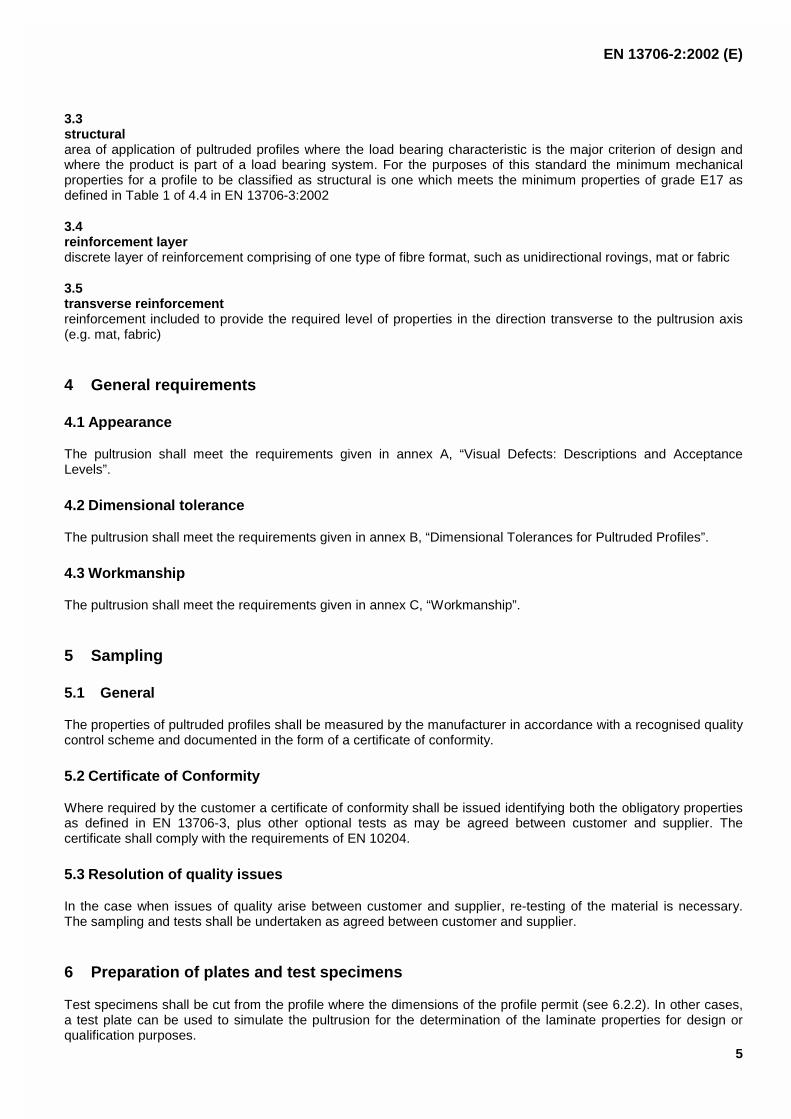
3.3structuralarea of application of pultruded profiles where the load bearing characteristic is the major criterion of design andwhere the product is part of a load bearing system. For the purposes of this standard the minimum mechanicalproperties for a profile to be classified as structural is one which meets the minimum properties of grade E17 asdefined in Table 1 of 4.4 in EN 13706-3:2002
3.4reinforcement layerdiscrete layer of reinforcement comprising of one type of fibre format, such as unidirectional rovings, mat or fabric
3.5transverse reinforcementreinforcement included to provide the required level of properties in the direction transverse to the pultrusion axis(e.g. mat, fabric)
4 General requirements
4.1 Appearance
The pultrusion shall meet the requirements given in annex A, “Visual Defects: Descriptions and AcceptanceLevels”.
4.2 Dimensional tolerance
The pultrusion shall meet the requirements given in annex B, “Dimensional Tolerances for Pultruded Profiles”.
4.3 Workmanship
The pultrusion shall meet the requirements given in annex C, “Workmanship”.
5 Sampling
5.1 General
The properties of pultruded profiles shall be measured by the manufacturer in accordance with a recognised qualitycontrol scheme and documented in the form of a certificate of conformity.
5.2 Certificate of Conformity
Where required by the customer a certificate of conformity shall be issued identifying both the obligatory propertiesas defined in EN 13706-3, plus other optional tests as may be agreed between customer and supplier. Thecertificate shall comply with the requirements of EN 10204.
5.3 Resolution of quality issues
In the case when issues of quality arise between customer and supplier, re-testing of the material is necessary.The sampling and tests shall be undertaken as agreed between customer and supplier.
6 Preparation of plates and test specimens
Test specimens shall be cut from the profile where the dimensions of the profile permit (see 6.2.2). In other cases,a test plate can be used to simulate the pultrusion for the determination of the laminate properties for design orqualification purposes.

EN 13706-2:2002 (E)
6
6.1 Manufacture of test plates
Test plates shall be manufactured in accordance with ISO 1268-6 using a flat strip die. For test specimens cut onlyin the direction of production, the flat strip shall be a minimum of 50 mm wide.
If properties perpendicular to the direction of production are required, the flat strip shall be a minimum of 250 mmwide.
The thickness of the flat strip shall be the same as the profile being simulated.
The raw materials used, the laminate construction and the production parameters (die temperature, pull speed,etc.) of the test plate shall match as closely as possible the intended production conditions of the profile beingsimulated.
6.2 Preparation of specimens
6.2.1 Dimensions
Test specimens shall be cut to the dimensions and tolerances given in the individual test methods.
6.2.2 Cutting of test specimens
Test specimens shall not be taken closer than 10 mm to the edges or change in section of a profile. The cutting oftest specimens shall be undertaken in such a way that any resultant edge defects do not adversely affect the testresults. One of the following three procedures may be used.
6.2.2.1 Milling
Test specimens may be cut from the test plaque using a duplicating or CNC milling machine.
6.2.2.2 Sawing
Test specimens may be cut from the test plaque using a circular saw fitted with a hardened metal or diamondedged saw blade. Alternative techniques such as laser or water jet cutting are also acceptable if meeting the abovequality requirements.
6.2.2.3 Pre-cutting
Test specimens may be cut by any convenient means to a minimum of 5 mm over the specified width of the testspecimen. 5 or 10 test specimens may then be packed together and milled to size as a block.
6.3 Profile full section test specimens
A profile full section test shall be used to determine the effective full section flexural modulus as required inclause 4 of EN 13706-3:2002 using the test method described in annex D.
Samples for the profile full section test shall be selected in accordance with the criteria given in clause 5 of thisPart 2.
The samples selected shall be cut square at the ends and of sufficient length for the intended test (see annex D ofPart 2), and free from obvious production or other defects as listed in annexes B and C.

EN 13706-2:2002 (E)
7
7 List of Properties
Table 1 defines the list of material properties which shall be specified and the test methods which shall be used ineach case to determine the property value.
Table 1 — List of properties which shall be specified and associated test methods
Property Unit Test Method
1.1 Full Section test GPa annex D, EN 13706-3
1.2 Tension modulus-axial GPa
1.3 Tension modulus-transverse GPa EN ISO 527-4
1.4 Tension strength-axial MPa
1.5 Tension strength-transverse MPa
1.6 Pin bearing strength- axial MPa annex E, Part 2
1.7 Pin bearing strength-transverse MPa
1.8 Flexural strength-axial MPa EN ISO 14125
1.9 Flexural strength- transverse MPa
1.10 Interlaminar shear strength-axial MPa EN ISO 14130
NOTE It should be noted that the stacking sequence of the different reinforcements formats (e.g. mat, rovings) produces a“sandwich type” layered structure, which results in different properties being obtained in flexural and tensile coupon tests. Theposition of the lay-up in the profile in webs and flanges results in similar differences between these coupon tests and the fullsection test. It is not possible to predict any of the values from data obtained from a different test mode or test direction.
Table 2 defines the list of material properties which may be specified by agreement between customer and supplierand the test methods which shall be used in each case to determine the property value.
Table 2 — List of properties which may be specified and associated test methods
Property Units Test Method
2.1 Compression strength -axial MPa EN ISO 14126
2.2 Compression strength - transverse MPa
2.3 Fibre content by weight % EN ISO 1172
2.4 Density kg/m3 ISO 1183
2.5 Poisson’s Ratio-axial EN ISO 527-4
2.6 Poisson’s Ratio-transverse
2.7 Thermal expansion-axial m/m °C ISO 11359-2
2.8 Thermal expansion-transverse m/m °C
2.9 In-plane shear modulus GPa ISO 15310
Recommended methods for the determination of a number of mechanical, thermal, chemical, environmental andelectrical properties are given in the Informative annexes F and G. Unless otherwise agreed between interestedparties, it is recommended that preference should be given to using these methods where applicable.

EN 13706-2:2002 (E)
8
8 Labelling
Each package shall be clearly identified with:
8.1 Reference to the designation code.
8.2 Product type.
8.3 Section dimensions.
8.4 Number of sections or the total length in metres.
8.5 Gross and net weight of the pallet.

EN 13706-2:2002 (E)
9
Annex A(normative)
Visual Defects: Descriptions and Acceptance Levels(see also annex C -Workmanship)
NOTE 1 These descriptions and levels are assessed by the unaided eye at a distance of 400 mm to 500 mm.
NOTE 2 Defect acceptable levels are on the basis that they cause no-adverse effect on mechanical performance of thepultruded profile.
NOTE 3 Some defects require examination of the cut end of a length of pultruded profile.
Table A.1
Name Definition Acceptance Level
Blister A rounded elevation of the pultruded surface withboundaries that may be more or less sharply defined.
NOTE The rounded elevation somewhat resembles inshape a blister on the surface of human skin. Blisters mayexist within the pultrusion as a hollow delaminated area(gas-filled) under a raised portion of the surface.
Permitted if formed between surfacing veiland next layer of reinforcement. Size notgreater than 15 % of width and not greaterthan 10 mm in any direction. No morethan 1 per 5 m of length.
Product shall meet test requirements andnot exceed dimensional tolerances.
Crack A visual separation that occurs internally or penetratesperpendicularly down from the pultruded surface to theequivalent of one full layer or more transverse to thereinforcement.
None
Crater A small, shallow pultrusion surface imperfection, greaterthan 1 mm in diameter.
None greater than 5 mm diameter and1 mm depth. No more than two per metrefor craters between 1 mm and 5 mmdiameter.
Delamination The visible separation of two or more layers or plies ofreinforcing material within a pultrusion.
None
Die Parting Line A lengthwise flash or depression on the surface of apultruded plastic part.
NOTE The die-parting line is associated with the areawhere separate pieces of the die join together to form thecavity.
The line projection caused by the die-parting line shall not extend past theproduct's surface by more than 0,20 mm. Itshall not create a sharp edge or haveloose fibres. Repair if limits exceeded.
Dullness A lack of normal pultruded surface gloss or shine.
NOTE This condition can be caused by insufficientcure locally or in large areas, resulting in the dull bandcreated on a pultruded part within the die when thepultrusion process is interrupted briefly (see Stop mark).
Permitted unless caused by insufficientcure.

EN 13706-2:2002 (E)
10
Table A.1 (continued)
Name Definition Acceptance Level
ExposedUnderlayer
The underlying layer of mat or roving not covered bysurface veil in a pultruded profile.
Permitted if surfacing material covers allbut 5 mm from each free edge but not toexceed 20 % of the width of the surfacebeing inspected
Fibre prominence A visible and measurable pattern of the reinforcing materialon the surface of a pultruded profile.
Permitted if reinforcing material isencapsulated by resin.
FoldedReinforcement
An unintentional or unspecified misalignment of mat orfabric reinforcing material in relation to the contour of apultruded section.
NOTE Such folds can or can not affect the surfaceappearance of the pultrusion and are chiefly visible in a cut crosssection of the product. Such reinforcement irregularities areusually due to shifting and crowding of the reinforcing materialduring pultrusion.
Not permitted if fold causes a deviation inlayer position greater than 20 % ofthickness or 1,5 mm out of its plane.
Fracture Cracks, crazing, or delamination, or a combination thereof,resulting from physical damage to the pultrusion.
None
Grooving Long narrow grooves or depressions in a surface of apultruded profile parallel to its length.
Permitted if material thickness reduction isnot over 10 % and groove width is 3 mm orless. May be continuous in a length.Grooves on opposing surfaces are notpermitted. Shall satisfy dimensional andmechanical requirements.
Inclusion Any foreign matter or particles greater than 1 mm in anydimension that are either encapsulated or imbedded in thepultruded profile.
None in excess of 5 mm in any dimension.No inclusion shall create a surface blemishabove the resin. Not more than 1 per metreof length.
Internal Dry Fibre A condition in which fibres are not fully impregnated byresin during pultrusion.
Permissible if area less than 0,5 mmdiameter and not more than 2 % of thecross-section, including Internal Porosity(Void).
Internal ShrinkageCracks
Longitudinal cracks in the pultrusion that are found withinsections of roving reinforcement.
NOTE This condition is caused by shrinkage strains duringcure that show up in the roving portion of the pultruded profilewhere transverse strength is low.
Permitted if the crack does not penetratean adjoining layer, reach the surface of theproduct or cause the product not to meetsthe test requirements.
Porosity, Internal(Void)
The presence of numerous voids beneath the pultrudedprofile surface, usually observable only in a cut crosssection.
Sum of pinhole porosity area and void areashall be no more than 2 % of cross-sectional area, including Internal Dry Fibre
Porosity, Surface(Void)
The presence of numerous visible pits or pinholes at ornear the pultruded profile surface, less than 1 mmdiameter.
Permitted if pits are less than 0,4 mm indiameter and 0.4 mm deep. Maximum of5 pits per 100 cm2 of area and no morethan one such area per 0,3 m of product.
Resin rich area An area of pultruded profile that lacks sufficientreinforcement
Permitted if product meets testrequirements (see also FoldedReinforcement).

EN 13706-2:2002 (E)
11
Table A.1 (continued)
Name Definition Acceptance Level
Saw Burn Blackening or carbonisation of a cut surface of a pultrudedprofile.
Permitted if product meets testrequirements.
Scale A condition wherein resin plates or particles are on thesurface of a pultruded profile.
NOTE Scales can often be readily removed, sometimesleaving surface voids or depressions.
Permitted if removal does not expose dryfibres and dimensional tolerances are met.
Stop Mark A band, either dull or glossy, on the surface, approximately12 to 100 mm long and extending around the periphery ofa pultruded profile.
NOTE This condition is the result of an interruption inthe normal continuous pulling operation.
Permitted unless other associated defects(such as scale, craters, porosity, chips,and gouges) exceed their permitted levels.
Under Cure Insufficient crosslinking of the resin.
NOTE Leads to lower mechanical performance and lowerBarcol hardness (e.g. less than 30).
None
WrinkleDepression
An undulation or series of undulations or waves on thesurface of the pultruded profile.
NOTE This condition can occur in either thelengthwise or crosswise direction of the pultruded profileand is caused by reinforcement shifting and crowding (seeFolded reinforcement). Wrinkles affect the flatness of thesurface.
Permitted if the product is still within thedimensional tolerance limits.

EN 13706-2:2002 (E)
12
Annex B(normative)
Dimensional tolerances for pultruded profiles
Table B.1
Property Tolerance
Wall thickness of open and closed profiles Nominal dimensions (mm)
Thickness T1 T2
0 to 2 ± 0,15 ± 10 %
2 to 5 ± 0,20 with
5 to 10 ± 0,35 minimum
± 0,45 of ± 0,30
Flatness in transverse direction Tolerance
F < 0,008 × B mm
Profile height and width of flange Nominal dimensions (mm)
B and H: ± 0,5 % with minimum ± 0,20 mm
and maximum ± 0,75 mm
Size of angle Tolerance
Y ± 1,5 °
EN 13706-2:2002 (E)
13
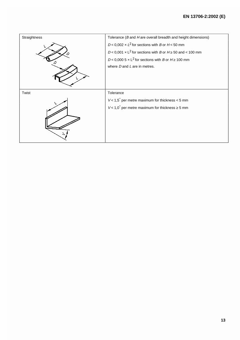
Straightness Tolerance (B and H are overall breadth and height dimensions)
D < 0,002 × L2 for sections with B or H < 50 mm
D < 0,001 × L2 for sections with B or H ≥ 50 and < 100 mm
D < 0,000 5 × L2 for sections with B or H ≥ 100 mm
where D and L are in metres.
Twist Tolerance
V < 1,5° per metre maximum for thickness < 5 mm
V < 1,0° per metre maximum for thickness ≥ 5 mm

EN 13706-2:2002 (E)
14
Annex C(normative)
Workmanship
C.1 Reinforcement geometry
C.1.1 Overlaps of mat: longitudinal
A minimum of 5 mm overlap should be used in closed sections.
Key
1 Pultruded profile axial direction
Figure C.1 – Overlaps of mat: longitudinal
C.1.2 Mat transverse splices
Splices shall not reduce the value of the minimum properties required for the grade in use.
Not more than one splice per laminate thickness shall be used, or 20 % of the mats for a laminate of more than fivelayers of transverse reinforcement, in a 1 m section of profile.
EN 13706-2:2002 (E)
15
Dimensions in millimetres
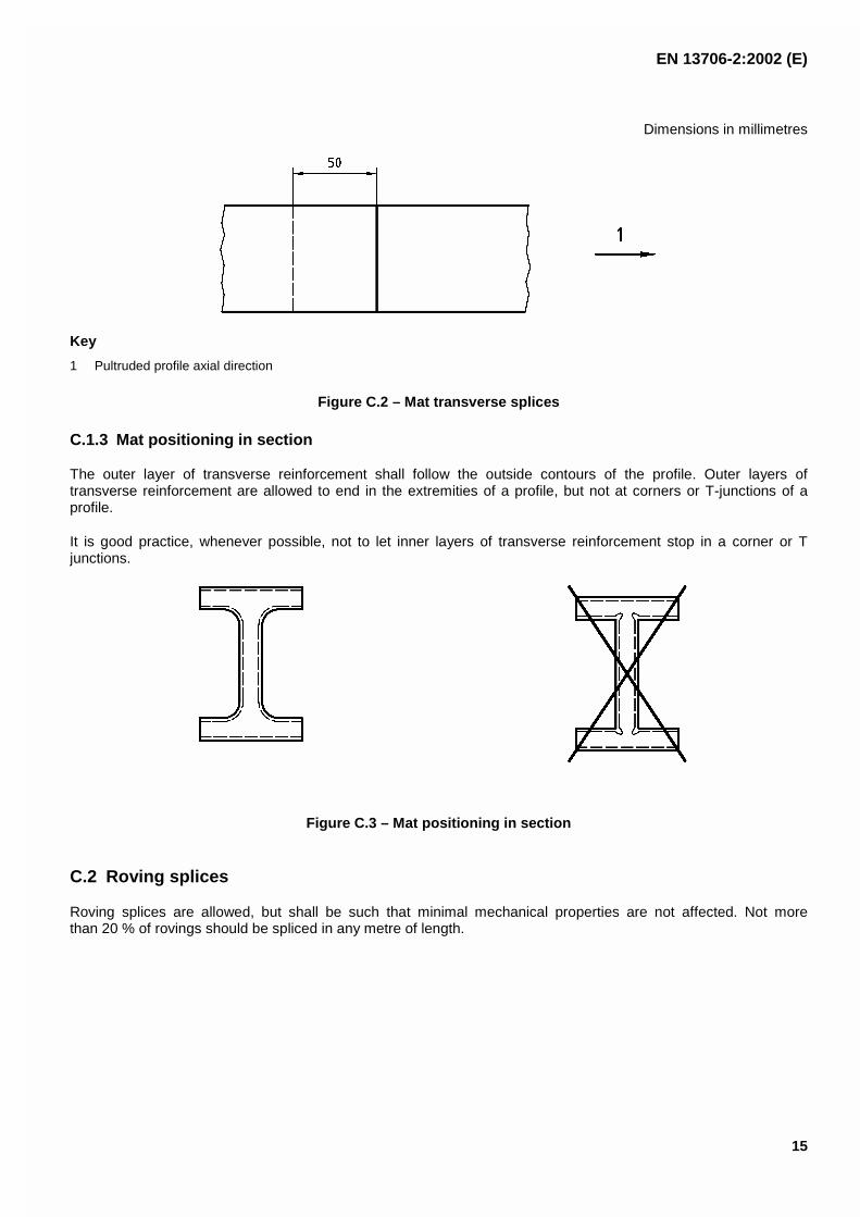
Key
1 Pultruded profile axial direction
Figure C.2 – Mat transverse splices
C.1.3 Mat positioning in section
The outer layer of transverse reinforcement shall follow the outside contours of the profile. Outer layers oftransverse reinforcement are allowed to end in the extremities of a profile, but not at corners or T-junctions of aprofile.
It is good practice, whenever possible, not to let inner layers of transverse reinforcement stop in a corner or Tjunctions.
Figure C.3 – Mat positioning in section
C.2 Roving splices
Roving splices are allowed, but shall be such that minimal mechanical properties are not affected. Not morethan 20 % of rovings should be spliced in any metre of length.
EN 13706-2:2002 (E)
16
Annex D(normative)
Determination of effective flexural modulus
D.1 General
D.1.1 This annex specifies a method for determining the effective flexural modulus of full sections of a pultrudedprofiles.
D.1.2 The method is suitable for symmetrical thin walled pultruded profiles.
An angle should be tested so that it does not twist, by testing two angles (bolted) back-to-back ( ).
D.1.3 A pultruded profile of regular cross section is loaded as a simple beam in three-point flexure at a test spanof 20 times the section depth with a tolerance of ± 10mm. From the slope of a plot of the load applied versus theresulting deflection the flexural stiffness is obtained.
NOTE The span to depth ratio is chosen to limit the reduction in the flexural modulus from unaccounted additionaldeflection due to the associated deformation in shear - see Figure D.1. The calculation in clause 7 includes a factor to correct,on average, for this effect.
D.1.4 This normative annex incorporates by undated reference, provisions from other publications. Thesenormative references are cited at the appropriate places in the text and the publications are listed hereafter. Thelatest edition of the publication referred to applies.
ISO 5893, Rubber and plastics test equipment - Tensile, flexural and compression types (constant rate oftraverse) - Specification.
Terms and definitions
For the purposes of this procedure, the following terms and definitions apply.
D.2.1flexural stiffness, Dflexural stiffness of a profile, expressed in N�mm2
D.2.2span, Ldistance between the two supports, expressed in millimetres, mm
D.2.3mid-span deflection, sdistance over which the bottom surface of the profile at the midspan of the specimen deviated from its originalposition, expressed in millimetres, mm
D.2.4speed of testing, vrate of relative movement between the supports and the loading edge, expressed in millimetres per minute,mm/min
D.2.5second moment of area, Isecond moment of area of the profile cross section. It is expressed in millimetres, mm4

EN 13706-2:2002 (E)
17
D.2.6effective flexural modulus, Eeff
modulus obtained by dividing the flexural stiffness by the second moment of area. It is expressed in GPa
D.2.7profile coordinate axesfor the pultruded profile the direction along the production direction, or axis of the profile, is defined as the “axial"direction and the perpendicular direction is defined as the “transverse" direction
NOTE The "axial" direction is also referred to as the 0 degree (0o), “1” or longitudinal direction, and the "transverse"direction as the 90 degree (90o) or “2” direction.
D.3 Apparatus
D.3.1 Test machine
D.3.1.1 General , the machine shall conform to ISO 5893 as appropriate to the requirements given in D.3.1.2and D.3.1.3.
D.3.1.2 Speed of testing , v, shall be kept constant according to ISO 5893.
D.3.1.3 Indicator for load , such that the error shall not exceed ± 1 % of the full scale (see ISO 5893).
D.3.1.4 Apparatus for measurement of mid-span deflection , s, the mid-span deflection shall be measuredto a precision of ± 1 % of the indicated value using, for example, a Linear Variable Differential Transducer (LVDT).
D.3.2 Loading member and supports , the radius of the loading member and supports, R1 and R2 respectively,shall be 100 mm and 50 mm minimum; They shall be circular in cross section to within 2 % of their diameter andshall be straight to within 1 % of their length.
The length of the loading member and supports shall be greater than the test specimen width, b. The loadingmember shall apply the load mid-way between the supports. The span distance between the supports shall beadjustable.
D.3.3 Micrometer , or equivalent, capable of reading to 0,01 mm, or less, for measuring the wall thickness, t, ofthe profile. The micrometer shall have contact faces appropriate to the surface being measured (i.e. flat faces forparallel, flat surfaces and hemispherical faces for other surfaces).
D.3.4 Rulers and Vernier callipers or equivalent , accurate to within 0,1 % of the distance being measured fordetermining the span length, L; and specimen height, h, and width, b.
D.4 Test specimens
D.4.1 Shape and dimensions
The specimen length shall be 1,2 times the test span, L.
D.4.2 Preparation of test pieces
Cut the test specimens to the required length from a pultruded profile.
D.4.3 Checking the test specimens
The specimens shall be straight and free of twist within the requirements detailed in annex B of this standard.

EN 13706-2:2002 (E)
18
D.5 Number of test specimens
Three test specimens shall be used.
D.6 Procedure
D.6.1 Test atmosphere
Conduct the test at ambient temperature (i.e. between 15 °C and 30°) unless otherwise agreed by the interestedparties (e.g. for testing at elevated or reduced temperatures).
D.6.2 Setting the test span
Measure, at four approximately equidistant points along the test specimen, the depth of the pultruded profile to thenearest ± 0,5 %. Use the average depth to set the test span according to D.1.3.
D.6.3 Conduct of the test
D.6.3.1 Speed of testing
Set the speed of testing so that the maximum deflection is achieved in 30 s to 90 s.
D.6.3.2 Specimen testing
Set the loading apparatus to the test span and place the test specimen symmetrically across the two parallelsupports. Apply the force uniformly across the width of the test piece by means of the loading member, parallel withand midway between the supports. Loading should continue until the specimen has been deflected to the requiredlevel.
D.6.3.3 Data collection
Record the force and midspan deflection throughout each test, using, if practicable, an automatic recording systemthat yields a load/displacement curve for this operation.
D.6.4 Determine the second moment of inertia
After testing, cut the profile into three equal portions and measure all dimensions of the cut section. Using meanvalues for each dimension calculate the second moment of inertia.

EN 13706-2:2002 (E)
19
D.7 Calculation and expression of results
Calculate the effective flexural modulus, Eeff, from the slope of the straight line fit through the data points of P
against s between s1 = L/500 and s2 = L/200 using the following equation:
Eeff = 1,05 D/l = 1,05 (P2 - P1)L3/48(s2 - s1)
where
I is the second moment of area of the profile in mm4;
D is the flexural rigidity in Nmm2;
P1, P2 are the load in newtons, N1, at s1 and N2 at s2;
s1 is the midpoint deflection equal to 4 500, mm;
s2 is the midpoint deflection equal to 4 200, mm;
Eeff is expressed in gigapascals, GPa.
NOTE The factor of 1,05 is a mean correction factor to allow for the uncorrected deflections due to the transverse shearstresses that occur in flexure loading in addition to the in-plane stresses.
The test result is the mean of the three values.
D.8 Test report
The test report shall include the following information:
a) a reference to annex D of this European Standard;
b) a complete identification of the material tested, including type, source, manufacturer's code number, form;
c) the date of measurement;
d) the dimensions of the test specimens;
e) the test span used;
f) the mean effective flexural modulus in GPa;
g) any operation not specified in this annex, as well as any incident likely to have affected the results.

EN 13706-2:2002 (E)
20
The error in effective flexural modulus (i.e. the degree of under estimation due to the unaccounted sheardeformation) as a function of test span is given in the following graph, for an average pultrusion.
Key
1 Test span/profile depth ratio
2 % error in flexure modulus
Figure D.1 — Error due to unaccounted shear deflection as a function of the ratio of test spar/profile depth

EN 13706-2:2002 (E)
21
Annex E(normative)
Determination of the pin bearing strength
E.1 Scope
E.1.1 This annex specifies a procedure for determining the pin bearing strength of fibre-reinforced plasticcomposites, with both thermoset and thermoplastic matrices.
E.1.2 A test specimen consisting of a strip of rectangular cross-section with a plain hole, centrally positioned, isloaded in double shear by a close fitting metallic pin. The maximum load sustained by the specimen is used todetermine the pin bearing strength based on the projected area of the pin in contact with the specimen.
E.1.3 This normative annex incorporates by undated reference, provisions from other publications. Thesenormative references are cited at the appropriate places in the text and the publications are listed hereafter. Thelatest edition of the publication referred to applies.
EN ISO 527, Plastics - Determination of tensile properties.
ISO 1268-6, Fibre-reinforced plastics - Methods of producing test plates - Part 6: Pultrusion moulding.
ISO 5893, Rubber and plastics test equipment - Tensile, flexural and compression types (constant rate oftraverse) - Specification.
NOTE This method uses the maximum load to define the pin bearing strength. This has been shown to be at a similar levelto the initial failure in the similar "torqued bolt" tests. The characterisation of "bolted" joints is very dependent on the actualconditions involved. This includes initial bolt torque (including any load lost in bolt threads), effect of relaxation due to visco-elastic effects, effect of hot/wet conditioning, washer size/over-size, bolt material, rivet details, chamfer depth and platethickness. Therefore, it is suggested that additional tests to the plain pin test be conducted for the actual joint conditions.
E.2 Terms and definitions
For the purposes of this annex, the following terms and definitions apply.
E.2.1pin bearing strength, σσpstress obtained by dividing the maximum load by the projected cross-sectional area of the pin contact area with thespecimen. The result is expressed in megapascals, MPa
E.2.2specimen coordinate axesdirection parallel with the production process is the axial direction and the direction perpendicular to the axialdirection is the transverse direction
NOTE The "axial" direction is also referred to as the “1”, 0 degree (0o) or longitudinal direction, and the "transverse"direction as the “2” or 90 degree (90o).

EN 13706-2:2002 (E)
22
E.3 Apparatus
E.3.1 Test machine
E.3.1.1 General, test machine conforming to ISO 5893 as appropriate to the requirements given in 3.1.2 and3.1.3.
E.3.1.2 Speed of testing , v, shall be kept constant according to ISO 5893.
E.3.1.3 Indicator for load , such that the error in the indicated force is less than ± 1 % of the full scale (seeISO 5893).
E.3.2 Micrometer , or equivalent, capable of reading to 0,01 mm, or less, and suitable for measuring thethickness h of the test specimen; and the hole diameter. The micrometer shall have contact faces appropriate tothe surface being measured (i.e. flat faces for parallel, flat surfaces and hemispherical surfaces for other surfaces).
E.3.3 Calipers , or equivalent, capable of reading to 0,1 mm for measuring the width b of the test specimen andthe hole position.
E.3.4 Loading jig : The pin is loaded by a double-shear metal plate assembly as shown in Figure 3. The platesshall allow a gap of 0,5 mm on either side of the specimen and shall not distort under the applied load. The loadingpin shall similarly not distort during the test and should be an interference fit unless specified otherwise.
E.4 Test specimens
E.4.1 Shape and dimensions
E.4.1.1 Specimen thickness less than or equal to 4 mm.
The specimen shall have a width of (36 ± 0,5) mm and a length of 180 mm. The width of individual specimens shallbe parallel to within 0,2 mm. The dimensions of the specimen are shown in Figure E.1.
A hole (6 ± 0,2) mm in diameter is machined within 0,1 mm of the specimen centreline and a distance of check36 mm (i.e. 6 × hole diameter) from the end of the coupon.
E.4.1.2 Specimen thickness greater than 4 mm.
Alternative specimens shall maintain a specimen thickness/hole diameter ratio of 1,5, and a specimen width/holediameter and end distance/hole diameter ratios of 6.
E.4.2 Preparation of specimens
E.4.2.1 General
The test specimens shall either be cut from a section of the profile or from a panel prepared in accordance withISO 1268-6.
E.4.2.2 End tab material (if required)
Providing failure does not occur at or within the grip, specimens can be tested with unbonded tabs or no tabs.Guidance on tabbing, if required, is given in annex A of EN ISO 527-4 and EN ISO 527-5.
E.4.2.3 Machining the specimens
The test specimen shall be cut and drilled without causing damage.

EN 13706-2:2002 (E)
23
E.4.3 Checking the test specimens
The specimens shall conform to the dimensional tolerances and visual aspects specified in this annex.
E.5 Number of test specimens
E.5.1 Five test specimens shall be tested.
E.5.2 The results from test specimens that do not fail by compressive bearing beneath the bolt contact area shallbe discarded and new specimens tested in their place. The number of unacceptable failures and their types shallbe recorded.
NOTE Unacceptable failure modes include pin permanent deformation or failure, pin shear out, tensile failure of plate andload buckling (i.e. specimen too thin).
E.6 Procedure
E.6.1 Test atmosphere: Conduct the test at ambient temperature (i.e. between 15 °C and 30°) unless otherwiseagreed by the interested parties (e.g. for testing at elevated or reduced temperatures).
E.6.2 Specimen dimensions: Measure the thickness of the test piece to the nearest 0,02 mm at the mid-point ofthe specimen. Measure the hole diameter to ensure within the required tolerance.
E.6.3 Testing speed: The speed of testing, v, shall be 1 mm/min.
E.6.4 Test conduct: Assemble the specimen and loading jig as shown in Figure E.2. Load the specimen tofailure.
E.6.5 Data collection: Record the load throughout the test.
E.6.6 Maximum load: Record the failure load.
E.6.7 Failure mode: Check and record the mode of failure (see E.5.2).
E.7 Calculation and expression of results
E.7.1 Calculate the pin bearing strength σp, expressed in megapascals, using the following equation, h
hd
F� p =
where
F is the maximum load, in newtons;
d is the diameter of the loading pin, in millimetres;
h is the thickness of the test specimen, in millimetres.
E.7.2 Calculate the arithmetic mean of the individual determinations to three significant figures.

EN 13706-2:2002 (E)
24
E.8 Test report
The test report shall include the following information:
a) reference to annex E of this European Standard;
b) complete identification of the material tested, including type, source, manufacturer's code number, form;
c) the date of measurement;
d) the dimensions of the test specimens, including the hole;
e) the size and grade of the loading pin;
f) the pin bearing strength expressed in megapascals;
g) the numbers and type(s) of failure obtained on rejected test specimens;
h) any operation not specified in this annex, as well as any incident likely to have affected the results.
Dimensions in millimetres
Key
1 Region for end-tabbing/alignment hole
2 Pin hole
3 End tabs (optional)
Figure E.1 — Fibre-reinforced plastic composite specimens showing hole position

EN 13706-2:2002 (E)
25
Key
1 Spacer plate (thickness = h + 1 mm)
2 Hardened steel side plate
3 Hardened steel bushes, sliding fit in side plates (optional)
4 Plain pin
5 Test specimen (h)
Figure E.2 — Loading plates and test arrangement

EN 13706-2:2002 (E)
26
Annex F(informative)
Recommended test methods for particular requirements
In the absence of other test methods covering additional requirements (e.g. chemical, fire resistance), the testmethods given in the following tables are recommended.
Table F.1 — List of test methods for other mechanical properties
Property Test method
F.1.1 Impact Resistance-Flexed plate and/orCharpy
ISO 6603-2, Plastics - Determination of puncture impact behaviour of rigidplastics - Part 2: Instrumented impact testing.
ISO 179, Plastics -- Determination of Charpy impact properties.
F.1.2 Creep behaviour ISO 899-1, Plastics - Determination of creep behaviour - Part 1: Tensilecreep.
ISO 899-2, Plastics - Determination of creep behaviour - Part 2: Flexuralcreep by three-point loading.
F.1.3 Fatigue behaviour ISO/DIS 13003, Fibre reinforced plastics - Determination of fatigueproperties under cyclic conditions.
F.1.4 Wear resistance ISO 6601, Plastics - Friction and wear by sliding - Identification of testparameters.
ISO 9352, Plastics - Determination of resistance to wear by abrasivewheels.
F.1.5 Barcol hardness EN 59, Glas reinforced plastics - Measurement of hardness by means of aBarcol impressor.
Table F.2 — List of test methods for thermal, chemical and environmental properties
Property Test method
F.2.1 Temperature of deflection underload. (TDUL/ HDT)
ISO 75-3, Plastics - Determination of temperature of deflectionunder load - Part 3: High-strength thermosetting laminates andlong-fibre-reinforced plastics.
F.2.2 Heat ageing IEC 60216-1, Electrical insulation materials – Properties ofthermal endurance – Part 1: Ageing procedures and evaluationof test results.
F.2.3 Water absorption. ISO 62, Plastics - Determination of water absorption.
F.2.4 Chemical resistance ISO 175, Plastics – Methods of test for the determination of theeffects of immersion in liquid chemicals.
F.2.5 Exposure to damp heat, waterspray and salt mist.
ISO 4611, Plastics - Determination of the effects of exposure todamp heat, water spray and salt mist.
F.2.6 Exposure to laboratory lightsource.
ISO 4892-1, Plastics - Methods of exposure to laboratory lightsources. - Part 1: General guidance.
ISO 4892-2, Plastics - Methods of exposure to laboratory lightsources - Part 2: Xenon-arc sources.

EN 13706-2:2002 (E)
27
Table F.3 — List of test methods for fire properties
Description Standard
F.3.1 Non-combustibility test EN ISO 1182, Reaction to fire tests for buildingproducts - Non-combustibility test (ISO1182:2002).
F.3.2 Reaction to fire - ignitability ISO 5657, Reaction to fire tests - Ignitability ofbuilding products using a radiant heat source.
F.3.3 Rate of heat release from building products(calorimeter)
ISO 5660-1, Fire tests - Reaction to fire - Part 1:Rate of heat release from building products -(Cone calorimeter method).
F.3.4 Fire resistance tests ISO 834, Fire-resistance tests - Elements ofbuilding construction.
F.3.5 Full-scale room test ISO 9705, Fire tests - Full-scale room test forsurface products.
F.3.6 Burning behaviour- guidance for developmentand use of fire tests
ISO/TR 10840, Plastics - Burning behaviour -Guidance for development and use of fire tests.
F.3.7 Determination of burning behaviour ISO 9773, Plastics - Determination of burningbehaviour of thin flexible vertical specimens incontact with a small-flame ignition source.
F.3.8 Combustibility of specimens using 125mm flamesource
ISO 10351, Plastics - Determination of thecombustibility of specimens using a 125 mm flamesource.
F.3.9 Plastics- Determination of flammability of oxygenindex
ISO 4589-1, Plastics - Determination of burningbehaviour by oxygen index -- Part 1: Guidance.
F.3.10 Building materials - Determination of calorificpotential
EN ISO 1716, Reaction to fire tests for buildingproducts - Determination of the heat ofcombustion (ISO 1716:2002).
F.3.11 Reaction to fire tests EN ISO 11925-2, Reaction to fire tests - Ignitabilityof building products subjected to directimpingement of flame - Part 2: Single flamesource test (ISO 11925-2:2002).
F.3.12 Single burning item test EN 13823, Reaction to fire tests for buildingproducts - Building products excluding flooringsexposed to the thermal attack by a single burningitem.
Several of these tests are included in EU standards for “fire classification for construction products and buildingelements” with associated criteria for each class. Further details are given in:
EN 13501-1, Fire classification of construction products and building elements - Part 1: Classification using testdata from reaction to fire tests.
prEN 13501-2, Fire classification of construction products and building elements - Part 2: Classification using datafrom fire resistance tests, excluding ventilation services.
NOTE The test methods given in Tables F.1 and F.2, and some in Table F.3 are general test methods for all plasticmaterials. In practice other test methods (possibly national standards or industrially accepted methods) can be more suitable forassessing the performance of a profile under given service conditions. Alternatively there can be national legal, contractual orinsurance industry requirements to use specific test methods. In these cases, test methods other than those listed in thesetables can be used.
EN 13706-2:2002 (E)
28
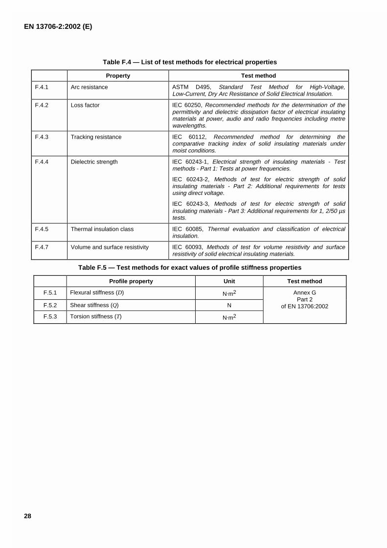
Table F.4 — List of test methods for electrical properties
Property Test method
F.4.1 Arc resistance ASTM D495, Standard Test Method for High-Voltage,Low-Current, Dry Arc Resistance of Solid Electrical Insulation.
F.4.2 Loss factor IEC 60250, Recommended methods for the determination of thepermittivity and dielectric dissipation factor of electrical insulatingmaterials at power, audio and radio frequencies including metrewavelengths.
F.4.3 Tracking resistance IEC 60112, Recommended method for determining thecomparative tracking index of solid insulating materials undermoist conditions.
F.4.4 Dielectric strength IEC 60243-1, Electrical strength of insulating materials - Testmethods - Part 1: Tests at power frequencies.
IEC 60243-2, Methods of test for electric strength of solidinsulating materials - Part 2: Additional requirements for testsusing direct voltage.
IEC 60243-3, Methods of test for electric strength of solidinsulating materials - Part 3: Additional requirements for 1, 2/50 µstests.
F.4.5 Thermal insulation class IEC 60085, Thermal evaluation and classification of electricalinsulation.
F.4.7 Volume and surface resistivity IEC 60093, Methods of test for volume resistivity and surfaceresistivity of solid electrical insulating materials.
Table F.5 — Test methods for exact values of profile stiffness properties
Profile property Unit Test method
F.5.1 Flexural stiffness (D) N�m2
F.5.2 Shear stiffness (Q) N
F.5.3 Torsion stiffness (T) N�m2
Annex GPart 2
of EN 13706:2002

EN 13706-2:2002 (E)
29
Annex G(informative)
Determination of flexural, shear and torsional stiffness properties
G.1 Scope
G.1.1 This annex specifies two methods for determining accurate values of the flexural, shear and torsionalstiffness properties of pultruded profiles.
G.1.2 The methods are suitable for symmetrical thin walled pultruded profiles but not angle profiles.
G.1.3 A pultruded profile of regular cross section is repeatedly loaded (elastically) as a simple beam:
Method A in three-point flexure at a number of different spans lengths (at a set strain rate and to a set strainlevel). The shear and bending contributions to the overall beam deflection vary with test span. Plotting theresults for each span as L2 vs s/PL and 1/L2 vs s/PL3, yields the flexural and shear stiffness.
NOTE The method is iterative, so that initial values should be estimated or known from similar profiles.
Method B in torsion at a number of offset loads. The torsional and bending contributions to the overallbeam deflection vary with loading off-set. Plotting the results for each off-set yields the torsional stiffness.
During the procedure the force applied to the specimen and the resulting deflection are measured.
G.1.4 This Informative annex incorporates by undated reference, provisions from other publications. Thesenormative references are cited at the appropriate places in the text and the publications are listed hereafter. Thelatest edition of the publication referred to applies.
ISO 5893, Rubber and plastics test equipment - Tensile, flexural and compression types (constant rate oftraverse) - Specification.
G.2 Terms and definitions
For the purposes of this procedure, the following terms and definitions apply.
G.2.1flexural stiffness, Dflexural stiffness of a profile. It is expressed in N�mm2
G.2.2shear stiffness, Qshear stiffness of a profile. It is expressed in newtons, N
G.2.3torsional stiffness, Ttorsional stiffness of a profile. It is expressed in N�mm2
G.2.4span, Ldistance between the two supports for Method A, and the distance between the centre-line edge of the clamp andthe centre-line of the drilled hole for Method B. They are expressed in millimetres, mm

EN 13706-2:2002 (E)
30
G.2.5critical length, lccritical length at which shear deformation contributes about 12 % of the total mid-point deflection under flexure. It iscalculated according to the relationship given in G.7.1.4. It is expressed in millimetres, mm
G.2.6beam deflection, sdistance over which the bottom surface of the profile in Method A deviates from its original position at the midspanof the specimen. It is expressed in millimetres, mm
G.2.7loading point deflection, wdistance over which the loading point in Method B deviated from its original position. It is expressed in millimetres,mm
G.2.8offset loading distance, Sdistance from the profile centreline to the loading point on offset arm (see Figure G.2). It is expressed inmillimetres, mm
G.2.9speed of testing, vrate of relative movement between the supports and the striking edge, expressed in millimetres per minute,mm/min
G.2.10second moment of area, Isecond moment of area of the profile cross section. It is expressed in millimetres, mm4
G.2.11profile coordinate axes:for the pultruded profile the direction along the production direction, or axis of the profile, is defined as the “axial"direction and the perpendicular direction is defined as the “transverse” direction
NOTE The "axial" direction is also referred to as the 0 degree (0o), “1” or longitudinal direction, and the "transverse"direction as the 90 degree (90o) or “2” direction.
G.3 Apparatus
G.3.1 Test machine
G.3.1.1 General , the machine should conform to ISO 5893 as appropriate to the requirements given in G.3.1.2and G.3.1.3. Alternatively, a dead-weight loading system can be used.
G.3.1.2 Speed of testing , v, should be kept constant according to ISO 5893. If used, the dead-weight loadshall be applied smoothly over a short period or in small uniform steps.
G.3.1.3 Indicator for load , such that the error should not exceed ± 1 % of the full scale (see ISO 5893). Fordead-weights loads no indicator is required but the loads should be known to within 1 %.
G.3.1.4 Apparatus for measurement of deflection, the mid-span deflection, s, and loading point deflection, wshould be measured to a precision of ± 1 % of the indicated value, using a dial gauge, Linear Variable DifferentialTransducer (LVDT) or equivalents.

EN 13706-2:2002 (E)
31
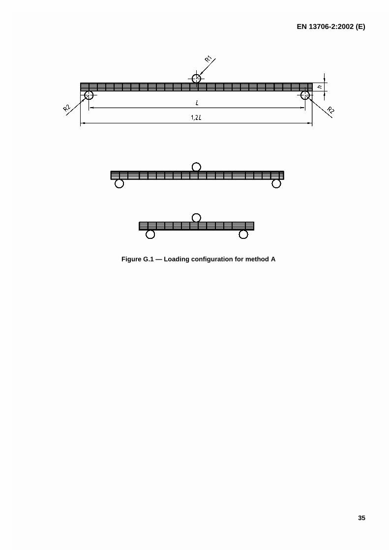
G.3.2 Loading member and supports for Method A
The radius of the loading member and supports, R1 and R2 respectively, shall be - 100 mm and 50 mm minimum.They shall be circular in cross section to within 2 % of their diameter and shall be straight to within 1 % of theirlength (see Figure G.1).
The length of the loading member and supports shall be greater than the test specimen width, b. The loadingmember shall apply the load mid-way between the supports. The span distance between the supports shall beadjustable.
G.3.3 Clamp and loading bar for Method B , where the clamp prevents any lateral or torsional movement ofthe profile. For thin-walled sections, it can be necessary to fill the section within the clamp region only, to avoidcollapse of the section.
A light, stiff rod of sufficient length, with an end stop, as shown in Figure G.2, is required. There should be no freemovement at the fixing point when the test loads are applied.
G.3.4 Micrometer , or equivalent, capable of reading to 0,01 mm, or less, for measuring the wall thickness h ofthe profile. The micrometer shall have contact faces. appropriate to the surface being measured (i.e. flat faces forparallel, flat faces and hemispherical faces for other surfaces).
G.3.5 Rulers and vernier callipers or equivalent , accurate to within 0,1 % of the distances beingmeasured for determining the span length, L; and specimen height, h, and width, b.
G.4 Test specimens
G.4.1 Shape and dimensions
Method A. The specimen length shall be 1,2 × the test initial test span.
Method B. The specimen shall have a total length-sufficient for the required gauge length (approximately 20 ×profile widest dimension) together with the length within the clamp and for the loading lever positioning.
G.4.2 Cut the test specimens to the required length from a pultruded profile. For Method B machine a holethrough the section at a point sufficiently away from the free end to avoid failure (e.g. 1 × profile widest dimension),midway between the top and bottom surface, to take the loading rod.
G.4.3 Checking the test specimens
The specimens shall be flat and free of twist within the requirements of the standard.
G.5 Number of test specimens
Two test specimens shall be tested for each method. For results differing by more than 5 % from each other, a thirdspecimen shall be tested.
G.6 Procedure
G.6.1 Test atmosphere: conduct the test in the same atmosphere as used for conditioning unless otherwiseagreed by the interested parties (e.g. for testing at elevated or reduced temperatures).
G.6.2 Determine the second moment of inertia: measure all dimensions of the section and calculate thesecond moment of inertia and cross-sectional area of the section.

EN 13706-2:2002 (E)
32
G.6.3 Method A
G.6.3.1 Span: choose the range of span lengths to cover values larger and smaller than the estimated criticallength, lc, of the profile being tested or to cover the range of the 3-point bend apparatus used. Spans should befairly evenly spaced over the selected range and a minimum of 5 spans shall be tested.
G.6.3.2 Speed of testing: load the specimen over a constant time period chosen in the range 30 s to 90 s.Use the same time period for each re-loading of the beam.
G.6.3.3 Displacement limit: The beam should be deflected to a displacement equal to L/200 (i.e. test spandivided by 200).
G.6.3.4 Specimen testing: set the loading apparatus to the largest span of the chosen range and place thetest specimen symmetrically across the two parallel supports. Apply the force uniformly across the width of the testpiece by means of the loading member, parallel with and midway between the supports. Loading should continueuntil the specimen has been deflected to the required level for each particular span. The specimen should then beunloaded.
This procedure should be repeated for each of the spans in the chosen range starting with the largest and finishingwith the smallest, adjusting the specimen length at each span to ensure that the specimen to span length ratio iskept at 1,2:1 (see Figure G.1). When adjusting the specimen length, equal lengths of material should be removedfrom both ends of the specimen so as to keep the same mid-span position.
G.6.3.5 Data collection: record the force and midspan deflection throughout each test, using, if practicable, anautomatic recording system that yields a load/displacement curve for this operation.
G.6.4 Method B
G.6.4.1 Offset lengths: choose a range of off-set lengths, s, which should be fairly evenly spaced over theselected range and a minimum of 5 spans shall be tested.
G.6.4.2 Specimen testing: set the profile in a rigid clamp. Place the loading bar through the profile. Apply theforce at the different off-set positions and at the zero offset (i.e. on the pultrusion axis). Loading should continueuntil the loading point has been deflected a distance equal to L/200 (i.e. the beam gauge length divided by 200).The specimen should then be unloaded.
This loading procedure is then repeated for each of the offsets in the chosen range. If permanent deformationobtained after any loading cycle, repeat all tests at a lower applied displacement and note change in test report(see 4.8).
G.6.4.3 Data collection: record the force and loading point deflection throughout each test for each offsetlength, using, if practicable, an automatic recording system that yields a load/displacement curve for this operation.
G.7 Calculation and expression of results
The test result is the mean of the two, or three (see G.5) values.
G.7.1 Method A
G.7.1.1 At each span, from a graph of deflection (s) (on the x-axis) against load (P) (on the y-axis) measure theslope (P/s in Newton per millimetre, N/mm) of the linear section of the plot.
Plot L2 (x-axis) against s/PL (y-axis) (see Figure G.3) and 1/L2 (x-axis) against s/PL3 (y-axis) (see Figure G.4) for allof the span lengths, L, tested. In addition individual values of L2, s/PL, 1/L2 and s/PL3 shall be tabulated.
G.7.1.2 Calculate the Flexural Stiffness, D, from the slope of the straight line through the data points ofL2 vs.s/PL (Figure G.3).

EN 13706-2:2002 (E)
33
where
D is the flexural rigidity in Nmm2;
P is the load in newtons, N;
s is the mid-point deflection, mm;
L is the test span, mm.
Eeff, expressed in gigapascals, is obtained using the following equation:
Eeff = D/I
where I is the second moment of area of the profile in mm4.
G.7.1.3 Calculate the Shear stiffness, Q, from the slope of the straight line through the data points of 1/L2 vs.s/PL3.
where
Q is the shear stiffness in N;
P is the load in newtons, N;
s is the mid-point deflection, mm;
L is the test span, mm.
The effective shear modulus, Geff, expressed in gigapascals, can be calculated using the following equation:
Geff = Q/A
where
A is the area of the profile cross section in mm2.
NOTE As a cross-check, the slope of L2 vs s/PL should agree with the intercept of 1/L2 vs s/PL3 and the intercept of L2 vss/PL should agree with the slope of 1/L2 vs s/PL2.
G.7.1.4 Calculate the critical length of the pultruded profile material from the following equation:
lc = (100D/Q)½
The critical length is shown for a the case where the shear deflection contributes 12 % to the total deflection. Acritical length value can also be calculated for other values of shear deflection if required. The test spans usedshould be larger and smaller than lc for the best analysis.
G.7.2 Method B
G.7.2.1 At each off-set length, from a graph of deflection (w) (on the x-axis) against load (P) (on the y-axis)measure the slope (w/P in millimetres per Newton, mm/N) of the linear section of the plot.
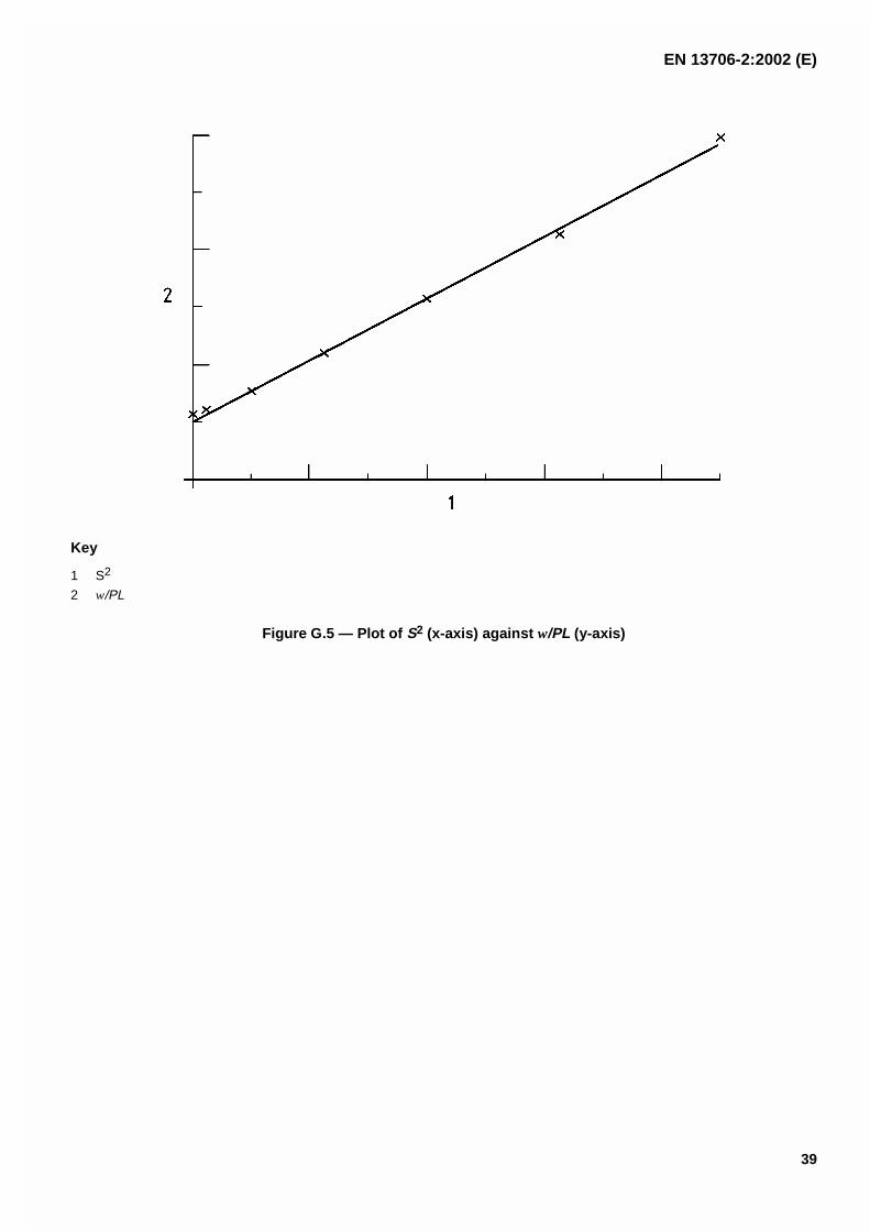
G.7.2.2 Calculate the Torsional Stiffness, T, from the slope of the straight line through the data points of S2 vs.w/PL (Figure G.2) where the slope equals L/T.
where

EN 13706-2:2002 (E)
34
T is the torsional rigidity in Nmm2;
P is the load in newtons, N;
w is the loading point deflection, mm;
L is the beam length, mm;
S is the beam offset length, mm.
G.8 Test report
The test report shall include the following information:
a) a reference to annex G of EN 13706-2;
b) a complete identification of the material tested, including type, source, manufacturer's code number, form;
c) the date of measurement;
d) the dimensions of the test specimens;
e) the radii of the loading member and the supports;
f) the test spans used (Method A);
g) the gauge length and offset spans used (Method B);
h) the number of specimens tested;
i) the mean flexural, shear and torsional stiffness values; as appropriate depending on whether Methods Aand/or B were used;
j) any operation not specified in this annex, as well as any incident likely to have affected the results.
EN 13706-2:2002 (E)
35
Figure G.1 — Loading configuration for method A

EN 13706-2:2002 (E)
36
Key
1 Clamp
Figure G.2 — Loading configuration for method B

EN 13706-2:2002 (E)
37
Key
1 Slope = 1/48 D
2 Intercept = ¼ D
3 s/PL (x 10-3 N-1)
4 L2 (x 106 mm2)
Figure G.3 — Plot of L2 (x-axis) against s/PL (y-axis)

EN 13706-2:2002 (E)
38
Key
1 Slope = ¼ Q
2 Intercept = 1/48 D
3 s/PL3 (x 10-9 N-1 mm-2)
4 1/L2 (x 10-6 mm-2)
Figure G.4 — Plot of 1/ L2 (x-axis) against s/PL3 (y-axis)
EN 13706-2:2002 (E)
39
Key
1 S2
2 w/PL
Figure G.5 — Plot of S2 (x-axis) against w/PL (y-axis)

EN 13706-2:2002 (E)
40
Bibliography
EN ISO 14126, Fibre-reinforced plastic composites - Determination of compressive properties in the in-planedirection (ISO 14126:1999).
EN ISO 1172, Textile-glass-reinforced plastics - Prepregs, moulding compounds and laminates - Determination ofthe textile-glass and mineral-filler content - Calcination methods (ISO 1172:1996).
ISO 1183, Plastics - Methods for determining the density and relative density of non-cellular plastics.
ISO 11359-2, Plastics - Thermomechanical analysis (TMA) - Part 2: Determination of coefficient of linear thermalexpansion and glass transition temperature.
ISO 15310, Fibre-reinforced plastic composites - Determination of the in-plane shear modulus by the plate twistmethod.