fibre channel consortium - unh interoperability · pdf filefibre channel consortium fc-pi-5...
TRANSCRIPT
Fibre Channel Consortium
FC-PI-5 Clause 6Optical Physical Layer Test Suite
Version 2.0
Technical Document
Last Updated: March 5, 2015
Fibre Channel Consortium 121 Technology Drive, Suite 2InterOperability Laboratory Durham, NH 03824University of New Hampshire Phone: +1-603-862-0090
Fax: +1-603-862-4181http://www.iol.unh.edu/consortiums/fc
© 2014 University of New Hampshire InterOperability Laboratory

The University of New HampshireInterOperability Laboratory
Table of ContentsTable of Contents............................................................................................................................................................2Acknowledgments...........................................................................................................................................................4Introduction.....................................................................................................................................................................5Group 1: Transmitter Verification..................................................................................................................................7
Test #6.1.1: Signal Rate.............................................................................................................................................8Test #6.1.2: Average Launched Power....................................................................................................................10Test #6.1.3: Optical Modulation Amplitude............................................................................................................12Test #6.1.4: Rise and Fall Times (4G)....................................................................................................................14Test #6.1.5: Transmitter Eye Mask.........................................................................................................................16Test #6.1.6: Transmitter Jitter (4G).........................................................................................................................18Test #6.1.7 Transmitter Waveform Distortion Penalty (TWDP) (8G Only)...........................................................20Test #6.1.8 Vertical Eye Closure Penalty (VECP) (16G Only)..............................................................................21
Appendix A: Test Setup................................................................................................................................................22Appendix B: Test Patterns............................................................................................................................................23
Fibre Channel Consortium 2 FC-PI-5 Clause 6 Optical Test Suite v2.0
The University of New HampshireInterOperability Laboratory
Modification Record● March 20, 2012 -Version 1.1
Michael Klempa: Added 16G specifications based off FC-PI-5 Rev 6.10, Clause 6.● March 5, 2015– Version 2.0
Daniel Gray: Editorial changes made as well as revised references. VECP test has been revised. 16GFC patterns have been revised throughout the document. Appendix A reflects our current setup.
Fibre Channel Consortium 3 FC-PI-5 Clause 6 Optical Test Suite v2.0
The University of New HampshireInterOperability Laboratory
AcknowledgmentsThe University of New Hampshire would like to acknowledge the efforts of the following individuals in the development of this test suite.
Daniel Gray University of New Hampshire Michael Klempa University of New HampshireJoshua Beaudet University of New HampshireDaniel Reynolds University of New HampshireA. Peter Keefe University of New HampshireMatthew Plante University of New Hampshire
Fibre Channel Consortium 4 FC-PI-5 Clause 6 Optical Test Suite v2.0
The University of New HampshireInterOperability Laboratory
IntroductionOverviewThe University of New Hampshire’s InterOperability Laboratory (UNH-IOL) is an institution designed to improve the interoperability of standards based products by providing an environment where a product can be tested against other implementations of a standard. This particular suite of tests has been developed to help implementers evaluatethe Physical Layer functionality of their optical Fibre Channel products.
These tests are designed to determine if a Fibre Channel product conforms to specifications defined in Clause 6 of the FC-PI-5 Rev 6.10 Fibre Channel Standard (hereafter referred to as “FC-PI-5”). The test also covers informationrelating to FC-MSQS Rev 3.2 Fibre Channel Standard (hereafter referred to as “FC-MSQS”). This test also covers information relating to FC-MJSQ Rev 14.1 Fibre Channel Standard (hereafter referred to “FC-MJSQ”). Finally, this test suite uses signaling guidelines defined by FC-FS-3 Rev 0.92 Fibre Channel Standard (hereafter referred to as “FC-FS-3”).
Successful completion of all tests contained in this suite does not guarantee that the tested device will operate with other devices. However, combined with satisfactory operation in the IOL’s interoperability test bed, these tests provide a reasonable level of confidence that the device under test (DUT) will function properly in many Fibre Channel environments.
Organization of TestsThe tests contained in this document are organized to simplify the identification of information related to a test and to facilitate in the actual testing process. Each test contains an identification section that describes the test and provides cross-reference information. The discussion section covers background information and specifies why the test is to be performed. Tests are grouped in order to reduce setup time in the lab environment. Each test contains the following information:
Test NumberThe Test Number associated with each test follows a simple grouping structure. Listed first is the Clause followed by the Test Group Number followed by the test's number within the group. This allows for the addition of future tests to the appropriate groups of the test suite without requiring the renumbering of the subsequent tests.
PurposeThe purpose is a brief statement outlining what the test attempts to achieve. The test is written at the functional level.
ReferencesThis section specifies all reference material external to the test suite, including the specific subclauses references forthe test in question, and any other references that might be helpful in understanding the test methodology and/or test results. External sources are always referenced by a bracketed number (e.g., [1]) when mentioned in the test description. Any other references in the test description that are not indicated in this manner refer to elements withinthe test suite document itself (e.g., “Appendix 6.A”, or “Table 6.1.1-1”)
Resource RequirementsThe requirements section specifies the test hardware and/or software needed to perform the test. This is generally expressed in terms of minimum requirements, however in some cases specific equipment manufacturer/model information may be provided.
Fibre Channel Consortium 5 FC-PI-5 Clause 6 Optical Test Suite v2.0
The University of New HampshireInterOperability Laboratory
Last ModificationThis specifies the date of the last modification to this test.
DiscussionThe discussion covers the assumptions made in the design or implementation of the test, as well as known limitations. Other items specific to the test are covered here.
Test SetupThe setup section describes the initial configuration of the test environment. Small changes in the configuration should be included in the test procedure.
ProcedureThe procedure section of the test description contains the systematic instructions for carrying out the test. It provides a cookbook approach to testing, and may be interspersed with observable results.
Observable ResultsThis section lists the specific observables that can be examined by the tester in order to verify that the DUT is operating properly. When multiple values for an observable are possible, this section provides a short discussion on how to interpret them. The determination of a pass or fail outcome for a particular test is often based on the successful (or unsuccessful) detection of a certain observable.
Possible ProblemsThis section contains a description of known issues with the test procedure, which may affect test results in certain situations. It may also refer the reader to test suite appendices and/or whitepapers that may provide more detail regarding these issues.
Fibre Channel Consortium 6 FC-PI-5 Clause 6 Optical Test Suite v2.0
The University of New HampshireInterOperability Laboratory
Group 1: Transmitter Verification
Overview:This group of tests verifies the optical signaling specifications for optical Fibre Channel signals, as defined in Clause6 of FC-PI-5.
Fibre Channel Consortium 7 FC-PI-5 Clause 6 Optical Test Suite v2.0

The University of New HampshireInterOperability Laboratory
Test #6.1.1: Signal Rate
Purpose: To verify that the signaling rate of the DUT's transmitter is within the conformance limit.
References:[1] FC-PI-5 - Clause 6[2] Ibid., Table 7
Resource Requirements: Digital oscilloscope capable of sampling a 16GFC signal at the appropriate wavelength. 0.5m – 5m fiber patch cord (MM). 2m – 5m fiber patch cord (SM).
Last Updated: August 22, 2014
Discussion: In order to ensure that a link partner’s receiver can track and recover the transmitter’s clock, it is important to
establish a tolerance on the amount of skew that the clock can have. This is obviously important since the recoveredclock is used to make decisions about where the bit boundaries are located in the signal. Reference [2] shows thenominal signaling rates for each link speed with a rate tolerance of ± 100 ppm, for MMF and SMF technologies.Furthermore, note 10 of reference [2] indicates that this tolerance must be maintained over a period of 200,000transmitted bits, which is approximately ten maximum length frames.
Table 1 - Signaling Speeds
4GFC 8GFC 16GFC
Nominal Signaling Rate 4.250 GBd 8.500 GBd 14.025 GBd
Rate Tolerance ± 100ppm (± 425000 Bd)
± 100ppm (± 850000 Bd)
± 100ppm (± 1402500 Bd)
Test Setup: The DUT should be setup as defined in Appendix A. Configure the DUT for the appropriate speed. The DUT
should be transitioned into the monitoring state.
Procedure:1) Instruct the Testing Station to transmit a LPB to the DUT.
For 4GFC, 8GFC Devices:2) Instruct the Testing Station to begin sourcing D21.5 continuously. 3) Measure the average TX signaling speed. The measurement should be made over a length of 200,000
transmitted bits. For 16GFC Devices:
2) For 16GFC devices, instruct the DUT to transmit 1010 continuously.3) Measure the average TX signaling speed. The measurement should be made over a length of 200,000
transmitted bits.
Fibre Channel Consortium 8 FC-PI-5 Clause 6 Optical Test Suite v2.0

The University of New HampshireInterOperability Laboratory
Observable Results:The average signaling rate, measured over 200,000 transmitted bits, shall be within the limits shown in Table 1.
Possible Problems: If the DUT does not support LPB (Loop Port Bypass), or sending of the above patterns, thenthe above measurements will be made with a set of continuous IDLE primitives or ARB(FF,FF) Primitives. For16GFC, if the DUT does not support sending of the above patterns, then the above measurements should be madeusing 64B/66B scrambled idle.
Fibre Channel Consortium 9 FC-PI-5 Clause 6 Optical Test Suite v2.0
The University of New HampshireInterOperability Laboratory
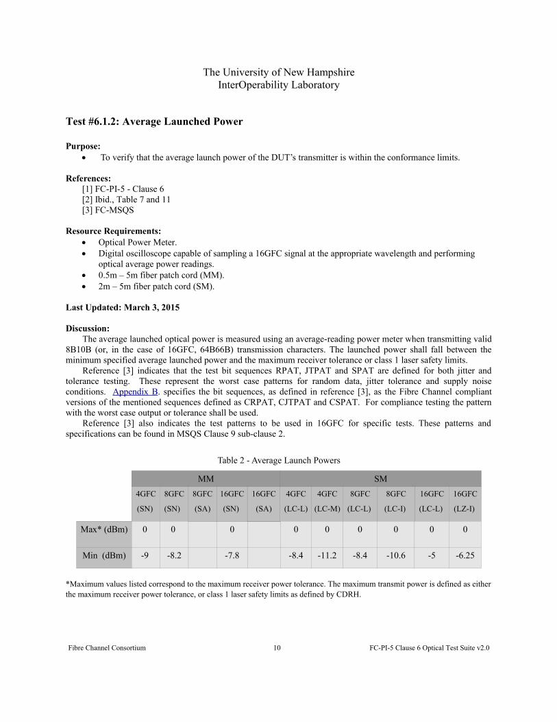
Test #6.1.2: Average Launched Power
Purpose: To verify that the average launch power of the DUT’s transmitter is within the conformance limits.
References:[1] FC-PI-5 - Clause 6[2] Ibid., Table 7 and 11[3] FC-MSQS
Resource Requirements: Optical Power Meter. Digital oscilloscope capable of sampling a 16GFC signal at the appropriate wavelength and performing
optical average power readings. 0.5m – 5m fiber patch cord (MM). 2m – 5m fiber patch cord (SM).
Last Updated: March 3, 2015
Discussion: The average launched optical power is measured using an average-reading power meter when transmitting valid
8B10B (or, in the case of 16GFC, 64B66B) transmission characters. The launched power shall fall between theminimum specified average launched power and the maximum receiver tolerance or class 1 laser safety limits.
Reference [3] indicates that the test bit sequences RPAT, JTPAT and SPAT are defined for both jitter andtolerance testing. These represent the worst case patterns for random data, jitter tolerance and supply noiseconditions. Appendix B. specifies the bit sequences, as defined in reference [3], as the Fibre Channel compliantversions of the mentioned sequences defined as CRPAT, CJTPAT and CSPAT. For compliance testing the patternwith the worst case output or tolerance shall be used.
Reference [3] also indicates the test patterns to be used in 16GFC for specific tests. These patterns andspecifications can be found in MSQS Clause 9 sub-clause 2.
Table 2 - Average Launch Powers
MM SM
4GFC
(SN)
8GFC
(SN)
8GFC
(SA)
16GFC
(SN)
16GFC
(SA)
4GFC
(LC-L)
4GFC
(LC-M)
8GFC
(LC-L)
8GFC
(LC-I)
16GFC
(LC-L)
16GFC
(LZ-I)
Max* (dBm) 0
0
0 0 0 0 0 0 0
Min (dBm) -9 -8.2 -7.8 -8.4 -11.2 -8.4 -10.6 -5 -6.25
*Maximum values listed correspond to the maximum receiver power tolerance. The maximum transmit power is defined as eitherthe maximum receiver power tolerance, or class 1 laser safety limits as defined by CDRH.
Fibre Channel Consortium 10 FC-PI-5 Clause 6 Optical Test Suite v2.0

The University of New HampshireInterOperability Laboratory
Test Setup: Use the fiber patch cord to connect the DUT to the Optical Power Meter (or appropriate oscilloscope). If an
oscilloscope is used the DUT should be setup as defined in Appendix A., configured for the appropriate speed and should be transitioned into the monitoring state.
Procedure:4GFC:
1) Instruct the Testing Station to transmit a LPB to the DUT.2) Instruct the Testing Station to begin sourcing CRPAT continuously.3) Measure the average launched power. 4) Repeat steps 2 and 3 with CJTPAT and CSPAT.
8GFC & 16GFC:1) Instruct the DUT to begin sourcing PRBS9 continuously.2) Measure the average launched power.3) Repeat steps 2 and 3 with Scrambled Idle.
Observable Results:The average launched power, of the worst value measured, shall fall between the maximum and minimum
limits shown in Table 2.
Possible Problems: Equipment to verify class 1 laser safety limits may not be available. If this is the case, thenverify the averaged launched power does not exceed the maximum receiver tolerance. If the DUT does not supportLPB (Loop Port Bypass), or sending of the above patterns, then the above measurements will be made with a set ofcontinuous IDLE primitives or ARB(FF,FF) Primitives. For 16GFC, if the DUT does not support sending of theabove patterns, then the above measurements should be made using 64B/66B scrambled idle only.
Fibre Channel Consortium 11 FC-PI-5 Clause 6 Optical Test Suite v2.0

The University of New HampshireInterOperability Laboratory
Test #6.1.3: Optical Modulation Amplitude
Purpose: To verify that the Optical Modulation Amplitude of the DUT’s transmitter is within the conformance
limits.
References:
[1] FC-PI-5 - Clause 6[2] Ibid., Table 7 and 11[3] Ibid., Clause 3.1.71[4] Ibid., Figure 25[5] FC-MSQS – Clause 9
Resource Requirements: Digital oscilloscope capable of sampling a 16GFC signal at the appropriate wavelength. 0.5m – 5m fiber patch cord (MM). 2m – 5m fiber patch cord (SM).
Last Updated: March 3, 2015
Discussion: Optical Modulation Amplitude (OMA) is defined as the positive difference in power between the averaged
value of logic one bits and the averaged value of logic zero bits. A long string of 8B10B encoding should beconsidered to be 5 bits high or 5 bits low.
For 16GFC, reference [5] indicates that the test patterns to be used for OMA measurements are limited to asquare wave pattern, or a sequence of eight logic one bits followed by eight logic zero bits.
Table 3 - OMA Values
MM SM
4GFC
(SN)
8GFC
(SN)
8GFC
(SA)
16GFC
(SN)
16GFC
(SA)
4GFC
(LC-L)
4GFC
(LC-M)
8GFC
(LC-L)
8GFC
(LC-I)
16GFC
(LC-L)
16GFC
(LZ-I)
Min (mW) 0.247 0.302 0.331 0.290 0.150 0.290 0.174 0.631 0.473
Min (dBm) -6.10 -5.20 -4.80 -5.40 -8.20 -5.40 -7.60 -2.00 -3.25
Test Setup: The DUT should be setup as defined in Appendix A. Configure the DUT for the appropriate speed. The DUT
should be transitioned into the monitoring state.Procedure:For 4GFC and 8GFC:
1) Instruct the Testing Station to begin sourcing K28.7 continuously.2) Configure the oscilloscope to capture the waveform data. 3) Measure the OMA.
Fibre Channel Consortium 12 FC-PI-5 Clause 6 Optical Test Suite v2.0

The University of New HampshireInterOperability Laboratory
For 16GFC:1) Instruct the Testing Station to begin sourcing a square wave.2) Configure the oscilloscope to capture the waveform data.3) Measure the OMA.
Observable Results:The optical modulation amplitude, of the worst value measured, shall fall above the limits shown in Table 3.
Possible Problems: If the DUT supports sending random bit patterns this test should be tested by measuring thestable 1 and stable 0 levels of the following pattern: 1111100000. If the DUT does not support sending of the abovepatterns, then the above measurements will be made with a set of continuous IDLE primitives or ARB(FF,FF)Primitives. For 16GFC, if the DUT does not support sending of the above patterns, then the above measurementsshould be made using 64B/66B scrambled idle.
Fibre Channel Consortium 13 FC-PI-5 Clause 6 Optical Test Suite v2.0
The University of New HampshireInterOperability Laboratory
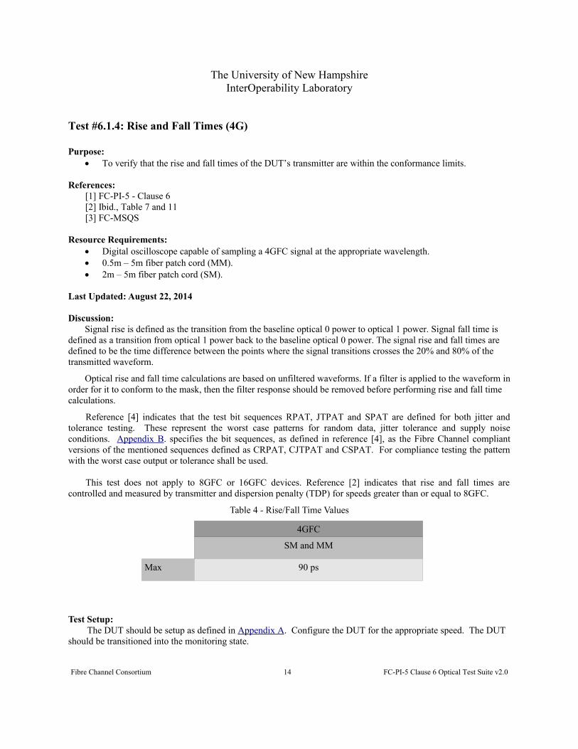
Test #6.1.4: Rise and Fall Times (4G)
Purpose: To verify that the rise and fall times of the DUT’s transmitter are within the conformance limits.
References:[1] FC-PI-5 - Clause 6[2] Ibid., Table 7 and 11[3] FC-MSQS
Resource Requirements: Digital oscilloscope capable of sampling a 4GFC signal at the appropriate wavelength. 0.5m – 5m fiber patch cord (MM). 2m – 5m fiber patch cord (SM).
Last Updated: August 22, 2014
Discussion: Signal rise is defined as the transition from the baseline optical 0 power to optical 1 power. Signal fall time is
defined as a transition from optical 1 power back to the baseline optical 0 power. The signal rise and fall times are defined to be the time difference between the points where the signal transitions crosses the 20% and 80% of the transmitted waveform.
Optical rise and fall time calculations are based on unfiltered waveforms. If a filter is applied to the waveform inorder for it to conform to the mask, then the filter response should be removed before performing rise and fall time calculations.
Reference [4] indicates that the test bit sequences RPAT, JTPAT and SPAT are defined for both jitter andtolerance testing. These represent the worst case patterns for random data, jitter tolerance and supply noiseconditions. Appendix B. specifies the bit sequences, as defined in reference [4], as the Fibre Channel compliantversions of the mentioned sequences defined as CRPAT, CJTPAT and CSPAT. For compliance testing the patternwith the worst case output or tolerance shall be used.
This test does not apply to 8GFC or 16GFC devices. Reference [2] indicates that rise and fall times arecontrolled and measured by transmitter and dispersion penalty (TDP) for speeds greater than or equal to 8GFC.
Table 4 - Rise/Fall Time Values
4GFC
SM and MM
Max 90 ps
Test Setup: The DUT should be setup as defined in Appendix A. Configure the DUT for the appropriate speed. The DUT
should be transitioned into the monitoring state.
Fibre Channel Consortium 14 FC-PI-5 Clause 6 Optical Test Suite v2.0
The University of New HampshireInterOperability Laboratory
Procedure:1) Instruct the Testing Station to transmit a LPB to the DUT.2) Instruct the Testing Station to begin sourcing CRPAT continuously.3) Configure the digital oscilloscope to capture the waveform data. 4) Measure the rise and fall times. 5) Repeat steps 2 through 4 with CJTPAT and CSPAT.
Observable Results:The rise/fall times, of the worst value measured, shall be no greater than the values shown in Table 4.
Possible Problems: If the DUT does not support LPB (Loop Port Bypass), or sending of the above patterns, then theabove measurements will be made with a set of continuous IDLE primitives or ARB(FF,FF) Primitives.
Fibre Channel Consortium 15 FC-PI-5 Clause 6 Optical Test Suite v2.0

The University of New HampshireInterOperability Laboratory
Test #6.1.5: Transmitter Eye Mask
Purpose: To verify that the transmitter eye of the DUT is within the conformance limits.
References:[1] FC-PI-5 - Clause 6[2] Ibid., Table 8 and 12. [3] Ibid., Figure 20 and 26 – transmitter eye diagram mask (4GFC)[4] Ibid., Figure 21 and 27 – transmitter eye diagram mask (8,16GFC)[5] FC-MSQS
Resource Requirements: Digital oscilloscope capable of sampling a 4GFC signal at the appropriate wavelength. 0.5m – 5m fiber patch cord (MM). 2m – 5m fiber patch cord (SM).
Last Updated: March 3, 2015
Discussion: The transmitter pulse shape characteristics are specified in the form of a mask of the transmitter eye diagram,
shown in reference [3]. The DUT must conform to this mask. The mask should be measured after applying thespecified fourth-order Bessel-Thomson filter. The points used to create this mask are found in reference [2]. Themeasurement shall be made while the DUT is transmitting CJTPAT.
For 4GFC, reference [5] indicates that the test bit sequences, RPAT, JTPAT and SPAT are defined for bothjitter and tolerance testing. These represent the worst case patterns for random data, jitter tolerance and supply noiseconditions. Appendix B. specifies the bit sequences, as defined in reference [4], as the Fibre Channel compliantversions of the mentioned sequences defined as CRPAT, CJTPAT and CSPAT. For compliance testing the patternwith the worst case output or tolerance shall be used.
For 8GFC, signaling the JSPAT pattern in FC-MSQS is used. Reference [1] indicates that for 8GFC a mask ata probability of 10-3 is applicable. Reference [5] indicates that the test pattern to be used for 16GFC is PRBS31 orScrambled IDLE.
Test Setup: The DUT should be setup as defined in Appendix A. Configure the DUT for the appropriate speed. The DUT
should be transitioned into the monitoring state.
Procedure:
For 4GFC:1. Instruct the Testing Station to transmit a LPB to the DUT.2. Instruct the Testing Station to begin sourcing CRPAT continuously.3. Configure the oscilloscope to capture the waveform data and place these waveforms into the mask
definition. 4. Process the captured waveform, observing the number of mask violations. 5. Repeat steps 2 through 4 with CJTPAT and CSPAT.
Fibre Channel Consortium 16 FC-PI-5 Clause 6 Optical Test Suite v2.0

The University of New HampshireInterOperability Laboratory
For 8GFC:1. Disable Scrambling/De-Scrambling on the DUT.2. Instruct the Testing Station to begin sourcing JSPAT continuously.3. Configure the oscilloscope to capture the waveform data and place these waveforms into the mask
definition. 4. Process the captured waveform, observing the number of mask violations.
For 16GFC:1. Instruct the DUT to begin sourcing PRBS31 continuously.2. Configure the oscilloscope to capture the waveform data and place these waveforms into the mask
definition.3. Process the captured waveform, observing the number of mask violations.
Observable Results:All waveforms shall not violate the eye mask at any point.
Possible Problems: If the DUT does not support LPB (Loop Port Bypass), or sending of the above patterns, then the abovemeasurements will be made with a set of continuous IDLE primitives or ARB(FF,FF) Primitives. For 16GFC, if theDUT does not support the sending of PRBS31, the measurements should be made using only 64B/64B ScrambledIdle.
Fibre Channel Consortium 17 FC-PI-5 Clause 6 Optical Test Suite v2.0

The University of New HampshireInterOperability Laboratory
Test #6.1.6: Transmitter Jitter (4G)
Purpose: To verify that the jitter of the DUT’s transmitter is within the conformance limits.
References:[1] FC-PI-5 - Clause 6[2] Ibid., Table 9 and 13. [3] FC-MSQS
Resource Requirements: Digital oscilloscope capable of sampling a 4GFC signal at the appropriate wavelength. 0.5m – 5m fiber patch cord.
Last Updated: August 22, 2014
Discussion: Reference [1] describes the maximum peak to peak deterministic and total transmit jitter for all variants of SMF
and MMF. The total jitter is the sum of deterministic and random jitter. These jitter values are specified at the 10 -12
probability. An ideal reference clock can be extracted from the data in post processing software or in a hardwaregolden PLL. All measurements are performed at the Gamma-T point. Reference [2] indicates that jittermeasurements at Gamma-T are limited by TDP/TWDP and therefore are not applicable measurements.
Reference [3] indicates that the test bit sequences RPAT, JTPAT and SPAT are defined for both jitter andtolerance testing. These represent the worst case patterns for random data, jitter tolerance and supply noiseconditions. Appendix B. specifies the bit sequences, as defined in reference [3], as the Fibre Channel compliantversions of the mentioned sequences defined as CRPAT, CJTPAT and CSPAT. For compliance testing the patternwith the worst case output or tolerance shall be used.
Table 5 - Max Jitter Values
4GFC
Max DJ 0.26 UI
Max TJ 0.44 UI
Test Setup: The DUT should be setup as defined in Appendix A. Configure the DUT for the appropriate speed. The DUT
should be transitioned into the monitoring state.
Procedure:1) Instruct the Testing Station to transmit a LPB to the DUT.2) Instruct the Testing Station to begin sourcing CRPAT continuously.3) Capture the waveform on the oscilloscope and computer the jitter values. 4) Repeat steps 2 and 3 with CJTPAT and CSPAT.
Observable Results:The total jitter, of the worst value measured, shall be less than the values shown in Table 5.
Fibre Channel Consortium 18 FC-PI-5 Clause 6 Optical Test Suite v2.0
The University of New HampshireInterOperability Laboratory
Possible Problems: If the DUT does not support LPB (Loop Port Bypass) then another method not defined willhave to be used to force the DUT to source CJTPAT.
Fibre Channel Consortium 19 FC-PI-5 Clause 6 Optical Test Suite v2.0
The University of New HampshireInterOperability Laboratory
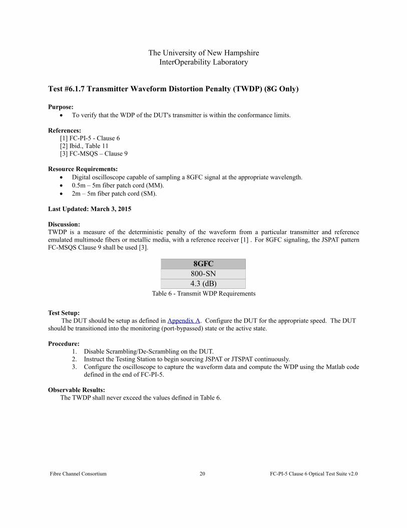
Test #6.1.7 Transmitter Waveform Distortion Penalty (TWDP) (8G Only)
Purpose: To verify that the WDP of the DUT's transmitter is within the conformance limits.
References:[1] FC-PI-5 - Clause 6 [2] Ibid., Table 11[3] FC-MSQS – Clause 9
Resource Requirements: Digital oscilloscope capable of sampling a 8GFC signal at the appropriate wavelength. 0.5m – 5m fiber patch cord (MM). 2m – 5m fiber patch cord (SM).
Last Updated: March 3, 2015
Discussion:TWDP is a measure of the deterministic penalty of the waveform from a particular transmitter and referenceemulated multimode fibers or metallic media, with a reference receiver [1] . For 8GFC signaling, the JSPAT patternFC-MSQS Clause 9 shall be used [3].
Table 6 - Transmit WDP Requirements
Test Setup: The DUT should be setup as defined in Appendix A. Configure the DUT for the appropriate speed. The DUT
should be transitioned into the monitoring (port-bypassed) state or the active state.
Procedure:1. Disable Scrambling/De-Scrambling on the DUT.2. Instruct the Testing Station to begin sourcing JSPAT or JTSPAT continuously. 3. Configure the oscilloscope to capture the waveform data and compute the WDP using the Matlab code
defined in the end of FC-PI-5.
Observable Results:The TWDP shall never exceed the values defined in Table 6.
Fibre Channel Consortium 20 FC-PI-5 Clause 6 Optical Test Suite v2.0
8GFC800-SN4.3 (dB)

The University of New HampshireInterOperability Laboratory
Test #6.1.8 Vertical Eye Closure Penalty (VECP) (16G Only)
Purpose: To verify that the WDP of the DUT's transmitter is within the conformance limits.
References:[1] FC-PI-5 - Clause 6 [2] Ibid., Table 11[3] FC-MSQS – Clause 2[4] Ibid., Clause 6[5] Ibid., Clause 9
Resource Requirements: Digital oscilloscope capable of sampling a 16GFC signal at the appropriate wavelength. 0.5m – 5m fiber patch cord (MM). 2m – 5m fiber patch cord (SM).
Last Updated: August 25, 2014
Discussion:VECP is a wave shape metric, a measure of performance degradation caused by deterministic dispersion. This istraditionally measured from an eye diagram, as discussed in FC-MSQS [3]. Algorithms related to VECP are detailedin the standard [4]. VECP measurements are defined by FC-PI-5 [2] for 16GFC devices only.
Table 7 - Transmit WDP Requirements
Test Setup: The DUT should be setup as defined in Appendix A. Configure the DUT for the appropriate speed. The DUT
should be transitioned into the monitoring (port-bypassed) state or the active state.
Procedure:1. Instruct the DUT to begin sourcing PRBS9 continuously. 2. Configure the oscilloscope to capture the waveform data and compute the VECP.
Observable Results:The VECP shall never exceed the values defined in Table 7.
Fibre Channel Consortium 21 FC-PI-5 Clause 6 Optical Test Suite v2.0
16GFC1600-SN2.56(dB)
The University of New HampshireInterOperability Laboratory
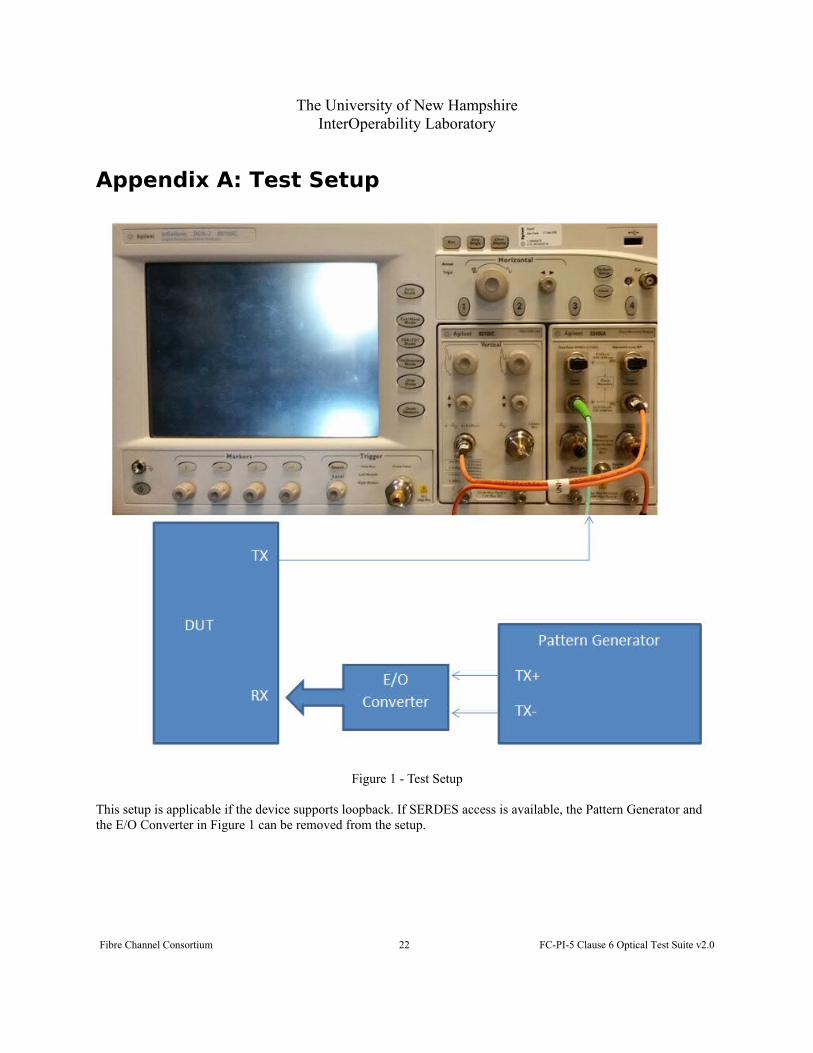
Appendix A: Test Setup
Figure 1 - Test Setup
This setup is applicable if the device supports loopback. If SERDES access is available, the Pattern Generator and the E/O Converter in Figure 1 can be removed from the setup.
Fibre Channel Consortium 22 FC-PI-5 Clause 6 Optical Test Suite v2.0

The University of New HampshireInterOperability Laboratory
Appendix B: Test Patterns
References:[1] FC-MJSQ – Table A.9, A.11, A.13[2] FC-PI-4 - Annex F, Table F.1[3] FC-MSQS
Table 8 - CJTPAT (JTPAT in a FC compliant frame format)
Table 9 - CRPAT (RPAT in a FC compliant frame format)
Table 10 - CSPAT (SPAT in a FC compliant frame format)
Fibre Channel Consortium 23 FC-PI-5 Clause 6 Optical Test Suite v2.0
Primitive Count(Idle) BC 95 B5 B5 6(SOFn3) BC B5 36 36 1
BE D7 23 47166B 8F B3 14
5E FB 35 59(CRC) EE 23 55 16 1(EOFn) BC B5 D5 D5 1
Primitive Count(Idle) BC 95 B5 B5 6(SOFn3) BC B5 36 36 1
7E 7E 7E 7E 417E 7E 7E 74 17E AB B5 B5 1B5 B5 B5 B5 12B5 5E 4A 7E 17E 7E 7E FE 1
(CRC) F5 2E F6 DD 1(EOFn) BC B5 D5 D5 1
The University of New HampshireInterOperability Laboratory
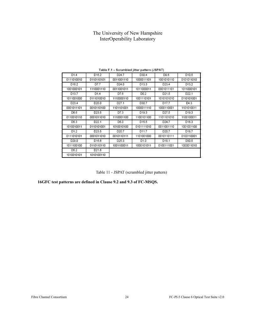
Table 11 - JSPAT (scrambled jitter pattern)
16GFC test patterns are defined in Clause 9.2 and 9.3 of FC-MSQS.
Fibre Channel Consortium 24 FC-PI-5 Clause 6 Optical Test Suite v2.0