fibre glass wind turbine blade manufacturing guide · 2016-06-20 · equipment before starting the...
TRANSCRIPT

Fibre glass wind turbine blade manufacturing guide
Produced by:
Engineers Without Borders (EWB - UK) & Sibol ng Agham at Teknolohiya (SIBAT - Philippines)
Version 1.4
1st May 2008
Authors: Andrew Corbyn & Matthew Little

1
Contents Contents ..........................................................................................................1 Introduction ......................................................................................................2
Overview of the production process .............................................................2 Health and Safety ............................................................................................4 Basic Design....................................................................................................5 Equipment required..........................................................................................6
Chemicals required ......................................................................................6 Tools required ............................................................................................10
Mould manufacture ........................................................................................11 Blade half manufacture ..................................................................................13
Materials required:......................................................................................13 Preparation.................................................................................................14 Lay-Up Procedure ......................................................................................22
Blade joining ..................................................................................................24 Blade trimming ...........................................................................................24 Blade root ...................................................................................................25 ‘Stringer’ manufacture ................................................................................25 Expanding foam .........................................................................................30 Blade finishing ............................................................................................33
Acknowledgements........................................................................................34 Appendix A: Quantities of materials ...............................................................35 Appendix B: Cost ...........................................................................................36 Appendix C: Labour .......................................................................................37 Appendix D: Forces on blades and testing ....................................................38 Appendix E: Blade deflection test ..................................................................40

2
Introduction This is a guide to the manufacture of fibre-glass wind turbine blades. These are for use with the wind turbine design produced by Hugh Piggott and described in detail in his ‘How to build a wind turbine: the axial flux windmill plans’ guide, available from http://www.scoraigwind.com/
An earlier version of Hugh Piggott’s guide, focussing on the electrical generator is available from the Practical Action website at: http://practicalaction.org/docs/energy/pmg_manual.pdf
This is a practical guide which is designed to show the process of producing a wind turbine blade from fibre-glass. This guide stemmed from work trying to produce a 1.8m blade for a 1kW version of Hugh’s design for use in the Philippines.
The blades are made from fibre glass, rather than wood as Hugh Piggott suggests, for a number of reasons:
• The time for manufacture will be much lower and a number of blades can be produced in one batch. This will also reduce costs.
• The use of moulds allows good repeatability and hence well balanced blades
• Good quality, straight grained wood was difficult and expensive to find in the Philippines. Also, due to lack of control over the logging industry, using some of the local hard woods would not be very sustainable.
A fibre glass blade construction guide has been produced by Practical Action and is available from: http://practicalaction.org/docs/energy/blades_manual.pdf
Such blades have been manufactured in Sri Lanka and in Peru, for smaller machines up to 500W. This is a guide to producing larger blades for a 1kW machine, along with more details on the production process.
This guide is exactly that – a guide. There are numerous other (probably better) techniques to use. This is documentation of the author’s experience. The authors would be very interested to hear other people’s experience and ideas.
It is presumed that the original blade has been correctly designed from an aerodynamic point of view. This is not a guide to the aerodynamic design of wind turbine blades.
Overview of the production process
The production process is as follows:
1. Produce an original blade from which to make copies. This would usually be carved from wood.
2. A fibre-glass female mould is then taken from the original. This mould is in two halves. This mould can be used a number of times.
3. The two halves of the blade are then made separately using a number of layers of glass fibre mat and resin.

3
4. When dry, these blade halves are then carefully cut and the edges tapered to that the two halves fit carefully together.
5. A wooden insert is fitted into the root of the blade. This provides material for which to screw into and provides some compressive strength.
6. A fibre-glass ‘stringer’ is fixed into one blade half. This is carefully cut down so that the other blade half fits exactly on top. This ‘stringer’ gives strength to the blade from root to tip.
7. Additional pieces of fibre glass mat are stuck to the ‘stringer’ using resin. This gives a large area onto which the other blade half can be stuck.
8. The other blade half is stuck onto the first. This is then fitted back into the mould and clamped together to ensure it dries in the correct shape.
9. A two-part expanding foam is then used to fill the blades.
10. Any imperfections in the blade are then filled with good quality filler which is then sanded back. A thin veil is added to the leading edge to join the two halves and for protection (this edge will be worn away in time due to the wind). The blade is then sanded to a smooth finish.
11. Depending upon the surface quality and desired finish, the blades may need to be painted.

4
Health and Safety Please follow the health and safety guidelines provided by the supplier. Here are some useful guidelines:
The process uses many different chemicals. Most of these are TOXIC and FLAMMABLE.
Ensure that they kept away from flames and sources of ignition at all times.
NO SMOKING at any point during the production process.
Wear GOGGLES, GLOVES, MASKS and PROTECTIVE CLOTHES while working with resin.
Most of the chemicals will cause agitation to the skin and cause blindness if they come into contact with the eyes. If any chemicals come into contact with the skin then wash immediately with plenty of soapy water. If any chemicals come in contact with the eyes the IMMEDIATELY SEEK MEDICAL HELP. Show the packaging of the chemical to the medical services.
ALWAYS follow the procedure shown in this guide when mixing chemicals.
COBALT AND HARDENER MUST BE KEPT SEPARATE AT ALL TIMES. If mixed they are explosive. This includes in syringes, mixing, cleaning and storage.
The fumes from the chemicals are TOXIC. ALWAYS work in a well ventilated environment. Wear a respirator mask.
The dust from cutting, sanding or grinding fibre glass is TOXIC. ALWAYS wear a good quality MASK and GOGGLES.
Power tools are used to cut and grind the fibre glass. Take great care when using these items and ALWAYS ensure GOGGLES and a MASK are worn.

5
Basic Design The basic blade shape is shown here. Please refer to ‘How to build a wind turbine: the axial flux windmill plans’ for full details of the shape, curve and size of the blade. This is the 6 foot (1kW) version of the wind turbine design.
Please note the definitions for Tip, Root, Leading edge, Trailing edge, Stringer, Wooden core, Windward side, Backward side as these will be used throughout this text.
30º
120º
1.8m (6’)
20cm (8”)
Drawing not to scale
View from front (which faces the wind)
View from side
Root
Tip
5cm (2”)
Leading edge
Trailing edgeView from tip end
Blade rotational direction
The blade is comprised of two main halves (both made from fibre glass), a wooden core at the root and a ‘stringer’ along the inside from root to tip. Once the blade has been constructed and stuck together, a two-part expanding foam is used to fill the structure of the blade helping to add strength and rigidity to the blades.
Windward side
Backward side
Wooden core
Stringer
“Exploded” view of blade construction
These lines are just to show curve of blade
The space within the blade is filled withtwo part expanding foam

6
Equipment required The blades are made from what is commonly referred to as fibre glass. This is mixture of glass fibre (maybe this is obvious, eh?), which has great strength in tension and compression, resin, which provides rigidity when set, and a number of other chemicals. The various chemicals required are listed here along with their use and any special precautions required.
The various tools required are also listed here. Ensure that you have all this equipment before starting the manufacturing process. Fibre glass product suppliers will typically stock all the materials and chemicals required.
Chemicals required
Resin
There are many different types of resin, each with different properties. To keep the design relatively simple, only two types of resin have been used for the blade manufacture:
Resin Type ‘R 10-03’
This is a general purpose rigid orthopthalic (FRP) polyester resin. (Type ‘R 10-03’ is a local manufacturer’s code number). It is relatively inexpensive and is used for the majority of the wind turbine blades.
Resin Type ‘Polymer 31-441’
This is called a ‘gel coat’ polyester resin. (Again, type ‘Polymer 31-441’ is a local manufacturer’s code number) It is 100% isophthalic with Neo-Pentyl Glycol (NPG). It is very hard wearing and is scratch and chemical resistant. It is more expensive than the other type of resin therefore its use is limited to just the outer layers of the blade.
Styrene Monomer
This is mixed with the resin to reduce the viscosity of the resin. This makes the resulting mixture more workable and easier to ‘paint’ onto the fibre glass cloth.

7
Hardener
Hardener is added to the resin mix to start the solidification (or curing) process. The time taken before the resin sets is controlled by the amount of hardener and accelerator (cobalt) added. Once the hardener is added to the resin it must be worked quickly into the fibreglass as the resin will solidify quickly.
An imported MEKP hardener is used due to its more reliable properties and hence more reliable resin setting time.
Cobalt
Cobalt is an 'accelerator' that speeds up the hardening process when added to the resin. This can be used to help control the setting time of the resin.
Toner
This only adds colour to the resin. It has no structural properties. It is used to colour the outer layers of resin, rather than paint the blades afterwards. This can be obtained in many different colours. Approx 5 to 10% by weight is added to the resin mixture until the correct colour is reached. Adding a greater amount than this may inhibit the solidification process. Adding toner makes the lay-up stage easier as you can clearly see where the resin is, however this makes the foam filling stage more difficult as the blade is then opaque.
Lowilite
This is a UV stabilizer and must be used on the outer layers of resin. It helps to prevent material degradation by sunlight. It is supplied in powder form.

8
Durawax
This is a release agent. It is applied to the mould before each ‘lay-up’ to ensure that the item produced does not stick to the mould.
Sometimes a thin non-stick film is added to moulds to avoid the part sticking – given the complex curved shape of the moulds a wax release agent was selected.
Fibre glass
Chopped strand fibre glass mat (CSM)
The fibres within CSM are in random orientation. This means that it has the same strength in every direction. It is the cheapest and easy to work with, as its orientation does not matter. It is available in different weights. 300gsm (grams per square meter) is used to produce the moulds and a thin ‘veil’ of 100gsm is used to join the sides and protect the leading edge.
Woven cloth fibre glass (WC)
This consists of woven strands. It is very strong in the direction of the weave but is slightly more expensive and harder to work with as the orientation of the weave when the piece is cut must be carefully chosen. The cut weave has a tendency to unravel when it is handled in a dry state. Only 200gsm is used here.
Thinners
Lacquer thinners are required to remove excess resin and to clean up any spills, paint brushes, pots and tools. It is extremely flammable.
Wooden core root
A small amount of marine-grade plywood is required to form a wooden core for the root of the blade. This was built up from a number of layers of plywood until the correct thickness was obtained.

9
Car body filler
A two-part car body filler is used to fill small blemishes and gaps on the final blades. Usually is supplied as a tin of resin with a small tube of hardener. The resin is a thermal-set plastic. The hardener, MEK peroxide, is a catalyst. The two components are mixed in a proportion of approximately 1% to 3% hardener to resin. Use a good quality brand.
Expanding foam
A two-part expanding polyurethane low density foam is used to fill the air gaps within the blade.
The foam is initially two liquids which must be mixed in a ratio of 1:1. This will then expand to 25 times its initial volume.
Such foam is used in boat building and construction. It may require a specialist supplier to source the product.
This foam may not be required and the structure can be left empty but we have found significantly improves the rigidity and strength of the blade.

10
Tools required
Safety equipment:
• Goggles
• Respirator / masks
o Ensure good quality item as the process generates large amounts of very fine toxic dust.
• Gloves
• Syringes (or pipettes)
• Pots and mixing sticks
• Scales
• Paint brushes
• Scissors
• Marker pens
• Rags/cloths
• Sandpaper
• Power grinder with cutting disk and sanding disk
• Mixing tools and spatulas for car body filler
11
Mould manufacture In order to create the fibre glass blades, an original sample must first be produced. A mould is then made from this sample. The mould can then be used to make numerous ‘copies’ of the original sample. This was the basic mould manufacture process used.
1: Firstly, a wooden wind turbine blade sample was built. The process to make this blade, along with its size and shape, is given in ‘How to build a wind turbine: the axial flux windmill plans’ guide.
This blade must be very accurately made as, once a mould is created, any imperfections will be repeated in all subsequent blades.
2: The outer surface of the wooden blade sample was given a layer of resin in order to create a hard surface. See ‘Blade half manufacture’ chapter for the resin mixture required. ‘Outer layer’ resin mixture was used. This was left to dry and then sanded down. Another layer of resin was then applied, again sanded down when dry. (Varnish should not be used as this may react with the resin).
Note: This step may not be necessary depending on the type of wood used (tests could be done on a scrap sample of wood first).
3: Once dry, a number of coats of wax must be built up on the wooden blade sample. At least five coats should be applied, buffing the surface after applying each layer. A good quality mould release wax should be used to do this (‘Durawax’ used in this case).
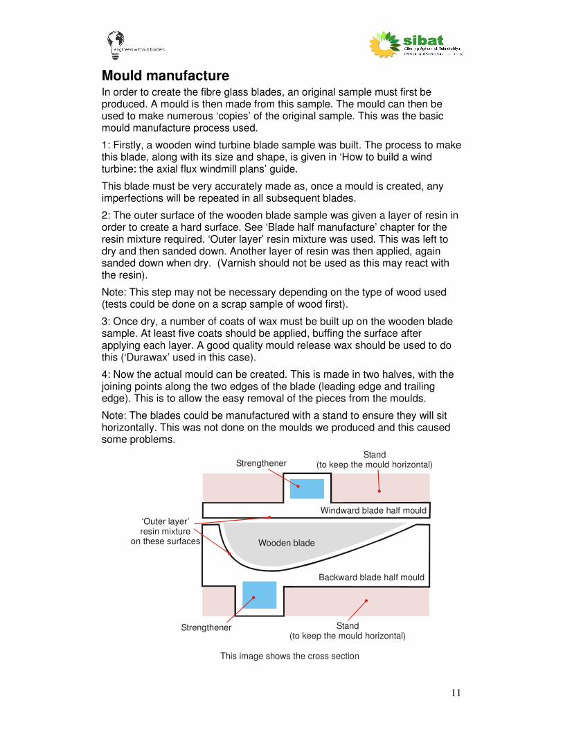
4: Now the actual mould can be created. This is made in two halves, with the joining points along the two edges of the blade (leading edge and trailing edge). This is to allow the easy removal of the pieces from the moulds.
Note: The blades could be manufactured with a stand to ensure they will sit horizontally. This was not done on the moulds we produced and this caused some problems.
Wooden blade
This image shows the cross section
Strengthener
Strengthener
Backward blade half mould
Windward blade half mould
‘Outer layer’ resin mixture
on these surfaces
Stand (to keep the mould ) horizontal
Stand (to keep the mould ) horizontal

12
To make one mould, the waxed wooden blade is covered on the correct side with hard ‘outer layer’ resin. Layers of chopped strand fibre glass mat (CSM) and additional resin are applied to build up a thick layer over the wooden blade. The thicker this layer is, the stronger it will be. In our case this was approximately 20 layers thick. The more expensive ‘outer layer’ resin need only be used for the first few layers. After this then cheaper ‘inner layer’ resin can be used. Also, to build up the mould, a mixture of resin and talc can be used to reduce the cost of the resin and to allow even drying of thick sections of resin.
Due to the length of the blade, this layer will not be rigid enough to be used as a mould (it may bend). Some form of additional strengthening is required. This must run along the whole length of the mould to stop it flexing. In this case a long piece of high density foam was used as a former. Fibre glass and resin were then applied around the foam to form a strong box section of fibreglass. When dry this made a very strong beam running the whole length of the mould. The former could also be a piece of wood – anything easily available to give strength to the mould. (nb. The rigidity in the mould comes from the ‘box section’ fibreglass – not the material of the former).
5: Repeat for the other side of the blade.
6: Cut the sides of the two mould halves so they fit together neatly.
7: Sand the inner surfaces of the mould well so that it is smooth. Any blemishes will appear when used to make the fibre glass blades.
WINDWARDMOULD
PAPERTEMPLATE
PLYWOODTEMPLATE
BACKWARDMOULD
PAPERTEMPLATE
PLYWOODTEMPLATE
It is estimated that moulds made in fibreglass have a life of 50-60 manufactured pieces.

13
Blade half manufacture As shown in the basic design, the blade is comprised of two blade halves, the windward half and the backward half. This section explains the process of producing the two blade halves (the next sections explain the process of joining the two halves and finishing the blade). Each blade half is built up from 16 layers of fibre glass mat. Woven cloth (WC) is used for additional strength in the direction the forces act on the blades.
This process requires careful preparation beforehand to ensure that the process of building the blade goes smoothly and quickly. If the resin is allowed to set while the blade halves are being manufactured then this could result in a weaker blade due to de-lamination between the two dry layers.
The general process is as follows:
1. Preparation: Cut the layers of fibreglass WC. 16 layers are used in each half.
2. Preparation: Prepare batches of resin mixture and the corresponding batches of hardener.
3. Preparation: Wax the mould to ensure easy release.
4. Procedure: Fill the moulds with a layer of resin, then a layer of fibreglass WC until all 16 layers have been placed. The weave of the WC must be rotated by 45 degrees between each layer.
5. Procedure: Leave to dry.
At least TWO people are required for this process. A third person would be useful.
Materials required:
For ONE blade:
Windward face Backward face Units Total
WC (200gsm) 2.5 2.5 kg 5 kg
Resin 31 441 0.5 0.75 litres 1.25 l
Resin 10 03 0.75 0.75 litres 1.5 l
Cobalt 5 10 cc 15 cc
Styrene Monomer 0.11 0.13 lt 0.25 lt
Toner 0.05 0.05 kg 0.1 kg
Lowilite 2 3 g 5 g
Hardener 17 20 cc 40 cc
Dura wax some some some
These quantities include any wastage (mainly wastage from cutting out the WC). This assumes the manufacturer is being careful to not waste materials. It is recommended to buy slightly more than required in case of any problems.
14
Preparation
Fibreglass
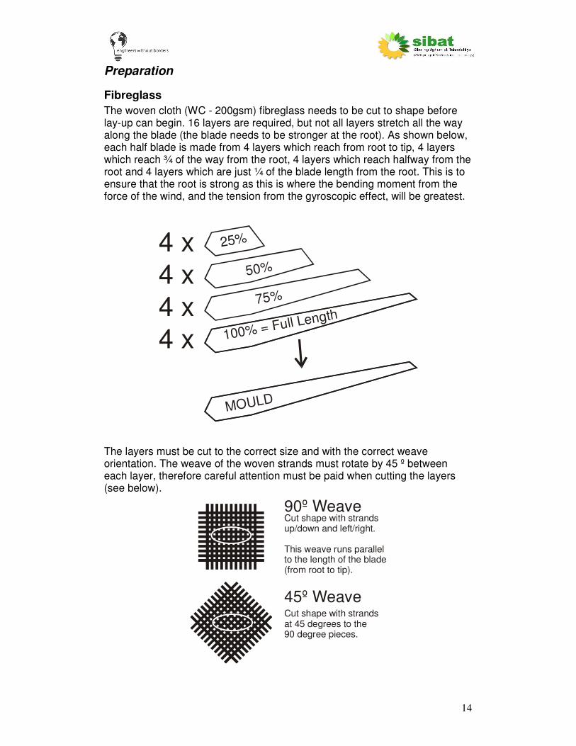
The woven cloth (WC - 200gsm) fibreglass needs to be cut to shape before lay-up can begin. 16 layers are required, but not all layers stretch all the way along the blade (the blade needs to be stronger at the root). As shown below, each half blade is made from 4 layers which reach from root to tip, 4 layers which reach ¾ of the way from the root, 4 layers which reach halfway from the root and 4 layers which are just ¼ of the blade length from the root. This is to ensure that the root is strong as this is where the bending moment from the force of the wind, and the tension from the gyroscopic effect, will be greatest.
100% = Full Length75%
50%
25%
MOULD
4 x
4 x4 x4 x
The layers must be cut to the correct size and with the correct weave orientation. The weave of the woven strands must rotate by 45 º between each layer, therefore careful attention must be paid when cutting the layers (see below).
90º Weave
45º Weave
Cut shape with strandsup/down and left/right.
This weave runs parallel to the length of the blade(from root to tip).
Cut shape with strandsat 45 degrees to the 90 degree pieces.
15
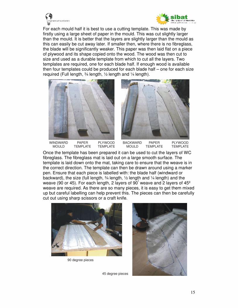
For each mould half it is best to use a cutting template. This was made by firstly using a large sheet of paper in the mould. This was cut slightly larger than the mould. It is better that the layers are slightly larger than the mould as this can easily be cut away later. If smaller then, where there is no fibreglass, the blade will be significantly weaker. This paper was then laid flat on a piece of plywood and its shape copied onto the wood. The wood was then cut to size and used as a durable template from which to cut all the layers. Two templates are required, one for each blade half. If enough wood is available then four templates could be produced for each blade half – one for each size required (Full length, ¾ length, ½ length and ¼ length).
WINDWARDMOULD
PAPERTEMPLATE
PLYWOODTEMPLATE
BACKWARDMOULD
PAPERTEMPLATE
PLYWOODTEMPLATE
Once the template has been prepared it can be used to cut the layers of WC fibreglass. The fibreglass mat is laid out on a large smooth surface. The template is laid down onto the mat, taking care to ensure that the weave is in the correct direction. The template can then be drawn around using a marker pen. Ensure that each piece is labelled with: the blade half (windward or backward), the size (full length, ¾ length, ½ length and ¼ length) and the weave (90 or 45). For each length, 2 layers of 90º weave and 2 layers of 45º
weave are required. As there are so many pieces, it is easy to get them mixed up but careful labelling can help prevent this. The pieces can then be carefully cut out using sharp scissors or a craft knife.
90 degree pieces
45 degree pieces

16
It is important to handle the fibreglass mat with care. The material is weakened if it is pulled out of shape so the fibres are not perpendicular, or if there is a discontinuity (such as the fibres are cut). Fibres at the edge of a piece can also easily be separated from the material, significantly weakening the edge portion.
Note: It may not be possible to cut the longer 45º weave pieces as one complete piece, due to the width of the supplied fibre glass sheet. In which case, these pieces must be cut as two halves, with an overlap to reduce the weakness. This is not ideal.
Once all the pieces have been cut out, the fibreglass layers for each size (full length, ¾ length, ½ length and ¼ length) should be weighed. These weights should be recorded as they are required to calculate the amount of resin needed. The weight of each blade should be equal (or within 10% of each other) to ensure that the blades will be balanced on the rotor.
When all the layers have been cut and the weight of the fibreglass recorded the layers can be laid out so that they are ready for use in the mould. The longest pieces are used first, so they should be on the top of the pile. The weave of the fibreglass should alternate between 90ºand 45º for consecutive layers. The first layer to be applied to the mould should be a 90º weave, full length piece.
4590
Etc.
9045
90
9045
Resin
The next step is to prepare the resin mixes. The resin batches are mixed but the hardener is NOT added. It is best to mix all the components except the hardener in one pot and measure out the hardener into another small pot

17
(plastic cups were used here). The pots with the resin batch and the hardener should be numbered to avoid any confusion. This should be done in advance of the lay-up procedure so that there is no delay while working, which could allow the resin to harden. The resin is prepared in a number of small batches, again so that the resin will not harden while it is being used.
The weight ratio of fibre glass mat to resin (including additives) should be approximately 1 : 2 (in practice this is closer to 1:1.8).
There are two types of resin mixtures required. One is used for the outer layers, one is used for the inner layers. The mixtures, including their properties and ratios are explained here:
“Outer layer” resin
This is a strong, hardwearing and scratch resistant outer layer, which is the first mixture to be used in the moulds (hence it is the outer layer). Resin type 31-441 is used, which is harder but also more expensive. Lowilite is also used in this mixture, which helps prevent UV (sunlight) degradation of the resin. Toner can also be used in this mixture to colour the blades, but this is purely aesthetic.
Percentage
Resin 31-441 100%
Styrene Monomer 10%
Cobalt 0.5%
Lowilite 0.5%
Toner (if used) 5-10%
Hardener 2%
“Inner layer” resin
This is a general purpose resin mix. This mixture is relatively strong but is less resistant to scratches and will degrade if exposed to UV light (eg. sunlight).
Percentage
Resin 10-03 100%
Styrene Monomer 10%
Cobalt 0.35%
Hardener 1.1%

18
In order to produce a blade the following batches of resin mixture should be prepared:
These batches can be split further into smaller quantities to avoid the resin curing before it is applied to the fibre glass, especially if this is the first blade produced or there are only two people producing the blade. Ensure that the ratios are kept exactly the same.
Resin mixing process
Although relatively simple, mixing the various components should be carried out in the correct order and with attention to health and safety. Wear gloves and goggles.
1. Place the mix pot on the scales. Adjust the scale to read zero. Add resin.
2. Add the styrene monomer. Mix thoroughly.
Component Windward half Backward half
Batch 1
Outer layer resin Resin 31-441 400g
560g
Styrene Monomer 40g 56g
Cobalt 2cc 2.7cc
Lowilite 2g 2.7g
Toner (if used) 20-40g 30-60g
Separate pot: Hardener 8cc 11cc
Batch 2
Inner layer resin Resin 10-03 200g 200g
Styrene Monomer 20g 20g
Cobalt 0.7cc 0.7cc
Separate pot: Hardener 2.2cc 2.2cc
Batch 3
Inner layer resin Resin 10-03 200g 200g
Styrene Monomer 20g 20g
Cobalt 0.7cc 0.7cc
Separate pot: Hardener 2.2cc 2.2cc

19
3. Add cobalt using a syringe (without the needle) or pipette. Mix thoroughly.
Warning: Keep cobalt and hardener separated at all times
4. Add the Lowilite powder (if used) using a clean spoon. Mix thoroughly.
5. Add toner (if used). Mix thoroughly. Ensure the mix pot is labelled with the batch number.
6. Measure out hardener into a separate pot, using a syringe or pipette. Ensure this is labelled with the matching batch number.
1 2
3a
4
3b
5

20
Warning: Keep cobalt and hardener separated at all times
Do NOT use the same syringe/pipette
Mould
Each time the two mould halves are used they must be thoroughly cleaned. An excess resin must be removed and any gaps or holes must be filled and sanded smooth.
The mould then requires waxing to ensure that the blade half is released easily and will not stick to the mould. ‘Durawax’ is used for this purpose. This must be applied liberally with a soft cloth. Ensure all surfaces that may be exposed to resin are covered. This must then be buff dried using a clean cloth or electric buffer (shown here). Repeat this process at least five times so that a thick layer of wax is built up. The mould can then be used.
Check point:
At this point ensure:
• The fibre glass WC should be cut and laid out.
• The resin mixtures and hardener required should be prepared.
• The mould should be prepared and waxed.
• You are wearing appropriate safety and protection gear.
6

21
STOP - “Is everything ready?”
Read through the lay-up procedure before starting

22
Lay-Up Procedure
You are now ready to do the lay-up procedure (combining the fibreglass with the resin to create a strong matrix). It is not important which half is layed up first, however the windward side is an easier and faster process.
It is important to lay up all the pieces in one run. If the resin on one layer is allowed to cure (go hard) before the next layer is applied, extra resin is required for the bottom surface of the materials. This increases the weight and reduces the strength due to a lamination between the two layers of resin.
Activate first batch of resin (‘outer layer resin’) by mixing in hardener.
Using paint brushes apply a thick layer of ‘outer layer’ resin to the mould.
Ensure resin is smoothly applied to all parts of the surface - any places without resin will show up on the outer surface of the final piece as a ‘dent’ in the surface.
Add the first layer of WC. This should be a 90º piece.
The material should be positioned by hand (using gloves, unlike shown here) before consolidating with a brush. This requires a 'stipple' action - press the brush into the fibres, do not use a 'brushing' action! One person should begin at the root, consolidating the material (stippling the fibres with a brush to pull through the resin applied to the mould surface - no additional resin is required
23
on the brush). The second person should follow the first, applying additional resin to areas that are without resin or that have less resin.
Carefully lay down the second layer of WCL, it should be a 45º piece. Continue with the same procedure of consolidation as before.
Use resin batch “inner layer” resin when the batch of “outer layers” resin is finished.
All 16 layers can be applied using this procedure. Keep mixing batches of “inner layer” resin as required. The amounts of resin indicated are intended as an exact amount to lay-up the 16 layers of fibre glass. When laying up, the resin usage should be monitored to avoid running out. If spare resin remains after all layers have been layed-up the excess resin can be added equally along the length of the blade. It is important the blades are the same weight so the rotor will be balanced.
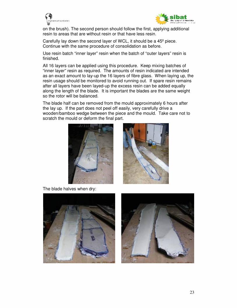
The blade half can be removed from the mould approximately 6 hours after the lay up. If the part does not peel off easily, very carefully drive a wooden/bamboo wedge between the piece and the mould. Take care not to scratch the mould or deform the final part.
The blade halves when dry:
24
Blade joining When set, the two halves of the blade need to be joined to form a single unit. To do this they need to be accurately cut so that the two pieces fit together. The join should be made with minimal impact on the blades aerodynamic shape. The final piece should appear as close to the original wooden mould as possible.
Also additional strength and rigidity is added to the blade through the use of a ‘stringer’ from the root to the tip. A wooden core is inserted at the root. This is so the screws used to hold the blades to the wind turbine have something to ‘bite’ into. It also stops the blade root collapsing when the front blade assembly is bolted onto the generator on the wind turbine.
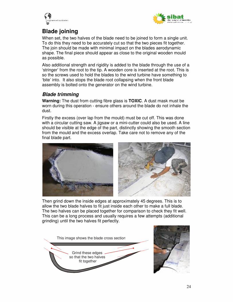
Blade trimming
Warning: The dust from cutting fibre glass is TOXIC. A dust mask must be worn during this operation - ensure others around the blade do not inhale the dust.
Firstly the excess (over lap from the mould) must be cut off. This was done with a circular cutting saw. A jigsaw or a mini-cutter could also be used. A line should be visible at the edge of the part, distinctly showing the smooth section from the mould and the excess overlap. Take care not to remove any of the final blade part.
Then grind down the inside edges at approximately 45 degrees. This is to allow the two blade halves to fit just inside each other to make a full blade. The two halves can be placed together for comparison to check they fit well. This can be a long process and usually requires a few attempts (additional grinding) until the two halves fit perfectly.
This image shows the blade cross section
Grind these edges so that the two halves
fit together

25
Blade root
A wooden core is required at the blade root - where the blade is screwed to the blade hub. The blade root should fit snugly in the root of the blade and go far enough down the blade so that all the screws will bite into the wood core. In this case the wooden piece was 7.5” width and 8” length at the longest part. This was made from a number of layers of plywood (marine grade if possible). In this case four layers of ½” plywood were used. This fitted well, although required some sanding down where the resin was not perfectly flat. The layers of plywood were glued together and clamped to form a single block. Once the part is dry the edges can be filleted to fit the inner surface of the blade.
‘Stringer’ manufacture
As shown in the blade design, a fibreglass ‘stringer’ is used through the wind turbine blade. This greatly adds rigidity to the blade which is important to prevent the blade snapping under the high bending force. The stringer is also used to hold the windward and backward blade halves together.
Cross-section of the blade to show the ‘Stringer’:
Approx 1/3 Approx 2/3
1: Make a thin (3-4mm thick), flat sheet of fibre glass. This must be at least as long as the blade (1.8m) and 20cm wide. This is made from at least three layers of 200gsm WC. This can be made by laying the fibre glass sheet on a flat, waxed surface. It can then be covered with the general purpose ‘inner layer’ resin mix. This will need approximately 200g of inner layer resin. Leave to dry (overnight).

26
2: Cut this sheet into three strips. Each strip needs to be as long as the blade as it will fit from the root all the way to the tip. It is better that it is too long and then cut shorter. It needs to be as wide as the blade’s thickness, again it is better to be too wide. The measurements used were 180cm by 6cm. At least one side and one end should be cut straight. This can be done with good scissors or tin-snips, or using a circular cutter, jigsaw or mini cutter.
3: Place this into the backward blade half, approximately one third of the blades width from the leading edge (7cm). Hold in position using weights, tape or blue-tack.
4: The stringer is stuck to the backward blade half using strips (approx. 4cm wide) of 200gsm WC and more of the general purpose ‘inner layer’ resin mixture.

27
Stringer
Glass fibre strips
Backward blade half
Apply resin (blue arrows)
Take care to ensure that the WC is kept vertical and is well stuck down (100g “inner layer” resin was used). Hold the stringer in place with a weight (a G-clamp was used here).
5: Leave this to dry (2hr minimum, overnight if possible).
6: When dry, the stringer must be cut (using tin snips) or ground down to the correct height using an angle grinder. Firstly grind slightly down at one point along the blade (it is best to start at the blade tip). Place a simple flat edge (ruler etc) at the grind point. When at the correct height, the ruler should rest on all three points: both edges and the stringer. If the straight edge does not lie flat, grind down slightly and test again with the straight edge. Do this until the straight edge lies flat on all three points. Be careful not to go too far.
Backward blade half
Stringer
Cut a ‘V’ notch into the stringer. It is at the correct depth when a straight rule exactly touches all three points, A, B and C
AB
C

28
A
B
C
Stringer
‘V’ notch
Repeat this at a number of points along the blade length (at least 6).
7: Then draw a straight line to join all the V-notch levels. Cut off the excess by cutting (using tin snips) or grinding along the line. We used a mixture of cutting, to remove the excess, then grinding carefully to the line.
Join notches with line
Stringer
Angle grinder/ other type of cutter
Cut down to the line
8: Check the windward blade half fits on top of the backward blade half. This is to ensure that the stringer has been cut down enough. There should be no gaps between the two halves. If there are, then the stringer should be filed down as necessary. Test again until the two blade halves fit well.
9: Stick on strips of 200gsm WC onto both sides of the stringer. This must be half stuck to the stringer piece and half left above the stringer. Use general purpose ‘inner layer’ resin mix (approx 100g). Carefully apply the resin only to the bottom half of the WC strip. Ensure that the top half of the fibre glass does not get any resin on it and is left flexible.
29
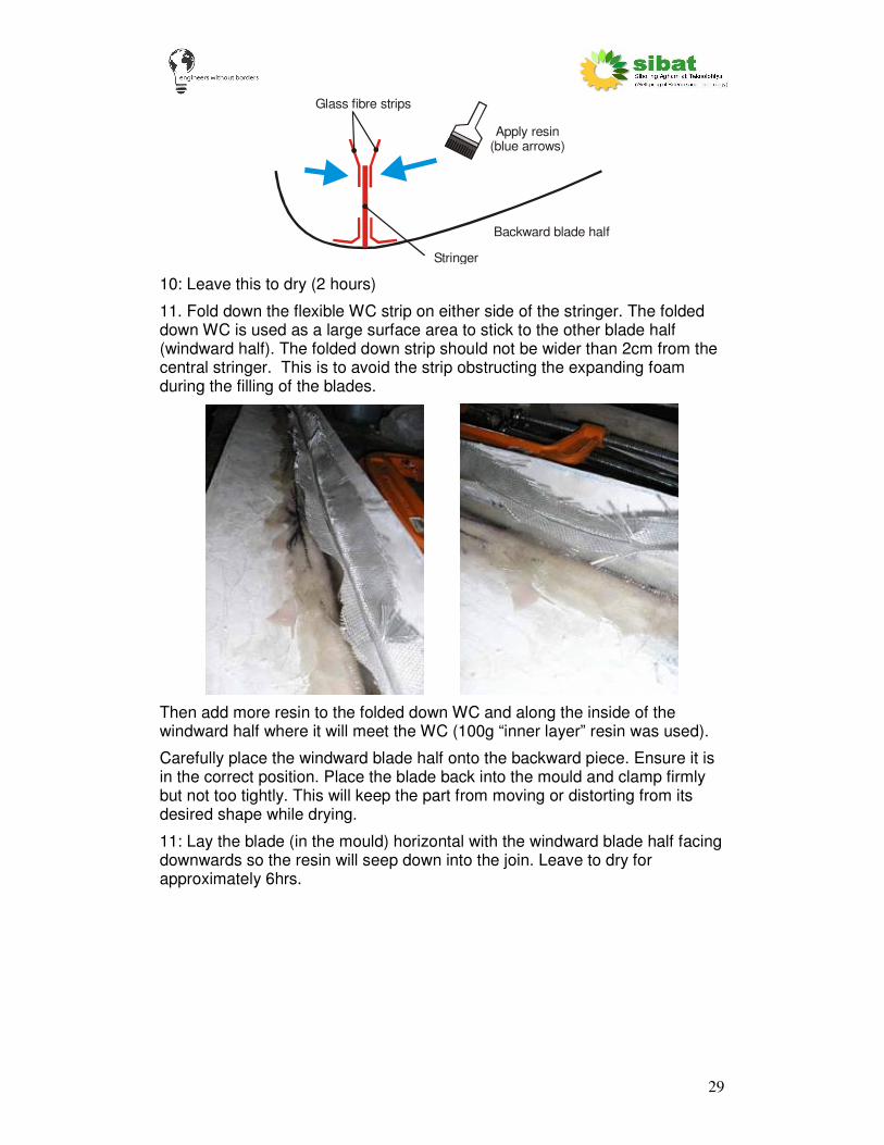
Stringer
Glass fibre strips
Backward blade half
Apply resin (blue arrows)
10: Leave this to dry (2 hours)
11. Fold down the flexible WC strip on either side of the stringer. The folded down WC is used as a large surface area to stick to the other blade half (windward half). The folded down strip should not be wider than 2cm from the central stringer. This is to avoid the strip obstructing the expanding foam during the filling of the blades.
Then add more resin to the folded down WC and along the inside of the windward half where it will meet the WC (100g “inner layer” resin was used).
Carefully place the windward blade half onto the backward piece. Ensure it is in the correct position. Place the blade back into the mould and clamp firmly but not too tightly. This will keep the part from moving or distorting from its desired shape while drying.
11: Lay the blade (in the mould) horizontal with the windward blade half facing downwards so the resin will seep down into the join. Leave to dry for approximately 6hrs.

30
The blade halves will now be stuck together. The space within the blade will be filled with expanding foam and the edges joined to finish the blade.
Expanding foam
A two-part expanding polyurethane low density foam was used to fill the air gaps within the blade. This helps with rigidity and structure.
The foam is initially two liquids which must be mixed in a ratio of 1:1. This will then expand to 25 times its initial volume.
To estimate the amount of foam required for each blade, the volume of the blade must be calculated. This was calculated using the water displacement method. The wooden blade (used to manufacture the mould) was immersed in a large bucket filled to the brim with water. The water displaced when the wooden blade was fully immersed was equal to the blade volume. The volume of water was measured. The volume of the wooden hub at the root was calculated and subtracted from the full blade volume. This gave an approximate volume for the space within the blade of around 7 litres. With the expansion ratio of 25, just 280ml of foam (140ml of each of the two liquids) was required to fill the inside of the blade.
Note: If there is no access to such foam, this stage might not be necessary.
The process to apply the foam is as follows:
1: Use masking tape to seal all the sides of the blade. This is to ensure that the foam, when in liquid form, will not flow out of the blade. Small holes must

31
be cut (using a pin or end of a knife) into the masking tape. This is to stop any pressure build up within the blade as the foam expands.
2: Put the blade back into the mould and clamp quite securely. This is to ensure that the blade will not be forced out of shape by the expanding foam.
3: The stringer through the blade creates two sides which both need to be filled. The following picture is viewed from the blade tip, which is still open.
Two sections due to stringer
The two sections are filled separately, with the foam left to cure in between each section. In order to insert the liquid foam mixture into the blade, two funnels are required (due to the small size of the openings). Funnels can be made from plastic sheet rolled into a cone. The funnel hole must be large enough to allow the foam mixture to run freely through (too small will mean that the foam starts to expand before it has all flowed into the blade section).
4: Prepare the two-part foam mix. Measure equal quantities of the two chemicals into correctly marked disposable containers (plastic cups were used here).
32
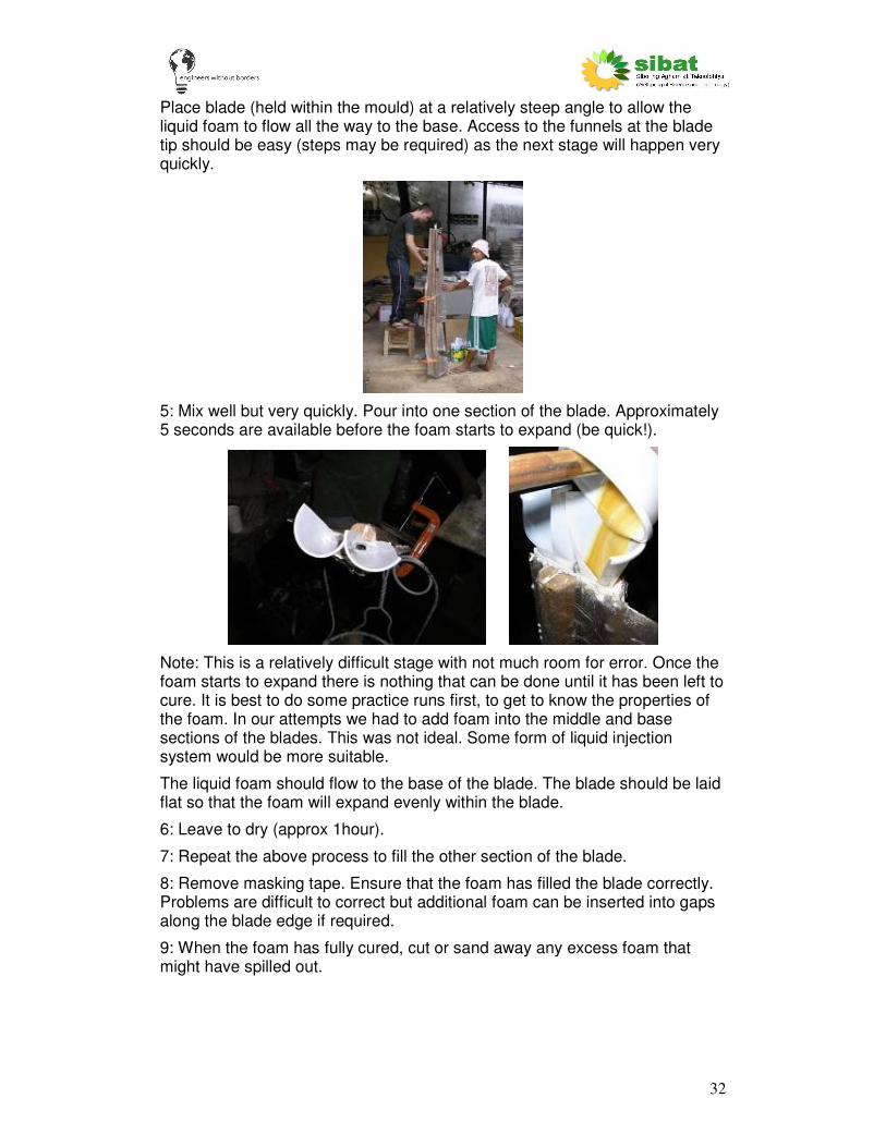
Place blade (held within the mould) at a relatively steep angle to allow the liquid foam to flow all the way to the base. Access to the funnels at the blade tip should be easy (steps may be required) as the next stage will happen very quickly.
5: Mix well but very quickly. Pour into one section of the blade. Approximately 5 seconds are available before the foam starts to expand (be quick!).
Note: This is a relatively difficult stage with not much room for error. Once the foam starts to expand there is nothing that can be done until it has been left to cure. It is best to do some practice runs first, to get to know the properties of the foam. In our attempts we had to add foam into the middle and base sections of the blades. This was not ideal. Some form of liquid injection system would be more suitable.
The liquid foam should flow to the base of the blade. The blade should be laid flat so that the foam will expand evenly within the blade.
6: Leave to dry (approx 1hour).
7: Repeat the above process to fill the other section of the blade.
8: Remove masking tape. Ensure that the foam has filled the blade correctly. Problems are difficult to correct but additional foam can be inserted into gaps along the blade edge if required.
9: When the foam has fully cured, cut or sand away any excess foam that might have spilled out.
33
Blade finishing
Now that the blade halves have been stuck together and filled with foam, the last stage is the blade finishing. This involves filling any gaps on the blade edges, adding a thin ‘veil’ of fibre glass to the leading edge, sanding down any imperfections and painting (if required).
Fill any gaps along the leading edge with good quality filler, such as car body filler. Leave this to dry.
Sand the blade along the leading edge and ensure that the surface is smooth.
Add a narrow strip of CSM fibreglass to the leading edge. Two layers should be applied. This is to help hold together the two blade halves and also to add an additional layer to help protect the leading edge. Lightweight 100gsm CSM was used for this, although 200gsm CSM may also work. Additional resin will be required and, as this will be exposed to the sun, this should be outer layer resin mixture. Approximately 200g of resin will be required. Once dry, sand again.
Fill any gaps on the blade surface with good quality filler, such as car body filler. Leave this to dry.
Sand the blade to ensure that all the surfaces are smooth, especially along the leading edge. The edge of the trailing edge should be thin, approximately 1mm or less width. This will be the final sanding process.
Clean the blade well to remove any dust or dirt.
If toner has not been used, the blades will need painting, both for protection and aesthetics. Good quality paint should be used, preferably with an undercoat layer. Spraying is the preferred (and easiest) method of application.
The blades are now complete! The next stage is to drill the holes to attach it to your wind turbine generator…..

34
Acknowledgements The authors wish to express their thanks to the following people and organisations:
EWB-UK (Engineers Without Borders – UK branch) – for providing funding for volunteer placements to carry out this work.
SIBAT (Sibol ng Agham at Teknolohiya) – An NGO based in the Philippines, who have provided help and support to implement a prototype 1kW wind turbine, including all the work presented within this guide.
Hugh Piggott – general guru and god of hand-built wind turbines.
VSO (Voluntary Service Overseas) – For providing funding for volunteer placements to help carry out this work.
World Bank – for funding the prototype 1kW wind turbine project.
Rich Harrison, Ben Hicks, Matthew Lewis and Marc Brinkmann and their supervisor Dr Mike Clifford of The University of Nottingham, UK – for their input on blade testing procedures.
Practical Action (formerly ITDG) – for publication of the fibre-glass wind turbine blade guide, along with other useful publications.
The people of Sitio Buli, Cabra Island, Occidental Mindoro, Philippines – for allowing a prototype wind turbine with fibre glass blades to be installed within their community, for putting up with our attempts to get the system running and for their generosity and hospitality whenever we have visited the site, no matter what problems there have been.

35
Appendix A: Quantities of materials Materials required for one blade and a set of three blades, along with additional items required for production:
Material Amount required
per blade (1) Unit Amount required per blade set (3) Unit
31441 Hard (top coat) resin 1.25 litre 3.75 litre
1003 general purpose resin 1.5 litre 4.5 litre
Styrene 0.28 litre 1 litre
Toner (white) 0.1 kg 0.3 kg
Lowilite 5 g 15 g
Cobalt 15 cc 45 cc
Hardener 50 cc 150 cc
Woven glass mat 200gsm 5 kg 15 kg
Woven glass mat 600gsm 0.1 kg 0.3 kg
Chopped strand mat 100gsm 0.02 kg 0.06 kg
2-part expanding foam 0.24 litre 0.75 litre
Other materials per blade set Quantity Unit
Syringes 4 pcs
Gloves 2 pair
Cloths 20 pcs
Thinners 4 litre
Sandpaper 3 yd
Durawax 0.2 litre
Brushes 2 pcs
Spray paint 3 cans
Disposable pots 10 pcs
Labour (approx) 10 Man-days

36
Appendix B: Cost These costs are in Filipino Pesos. This is a rough guide and some costs may be very different in other countries. This lists just the consumable materials required for the blades – it does not include the costs of the tools required nor the cost of producing the moulds.
Material Amount required per blade Unit Cost per Container Amount per blade set (3) Unit Cost per blade set % of cost
31441 Hard (top coat) resin 1.25 litre 171.50 3.75 litre 643.13 7.1
1003 general purpose resin 1.5 litre 126.75 4.50 litre 570.38 6.3
Styrene 0.28 litre 129.00 0.84 litre 108.36 1.2
Toner (white) 0.1 kg 252.00 0.30 kg 75.60 0.8
Lowilite 5 g 3.50 15.00 g 52.50 0.6
Cobalt 15 cc 1.27 45.00 cc 57.00 0.6
Hardener 50 cc 0.38 150.00 cc 57.50 0.6
Woven cloth (WC) 200gsm 4 kg 198.00 12.00 kg 2376.00 26.2
Chopped strand mat (CSM) 100gsm 0.02 kg 117.00 0.06 kg 7.02 0.1
2-part expanding foam 0.24 litre 625 0.72 litre 450.00 5.0
4397.48
Other materials per blade set Quantity Unit Cost per unit Cost per blade set
Syringes 4 pcs 50 200 2.2
Gloves 2 pair 100 200 2.2
Cloths 20 pcs 2 40 0.4
Thinners 4 litre 54.5 218 2.4
Sandpaper 1 m 240 240 2.6
Durawax 0.2 litre 260 52 0.6
Brushes 2 pcs 80 160 1.8
Spray paint 3 cans 150 450 5.0
Disposable pots 10 pcs 10 100 1.1
Labour 10 Man-days 300 3000 33.1
4660
TOTAL BLADE SET (3) COST: 9057.48

37
Appendix C: Labour This is meant as an approximate guide only. Some jobs require at least two people. It assumes all materials have been procured.
Job Approx Man-days
Total for mould manufacture 10 man-days
Cut fibre glass mat 1
Lay-up blade half - 6 required: 3 x windward, 3 x backward 5
Stringer attachement and blade half joining 1
Foam insertion 1
Balde finishing 2
Total for blade set (3 blades) (assume moulds created) 10 man-days

38
Appendix D: Forces on blades and testing This information may be useful to those testing the blades presented here.
Forces on the wind turbine blades
There are three main forces acting on the wind turbine blade. These are:
Centrifugal
This is due to the rotation of the blades. It is an inertial force which depends upon the rotational speed. According to the ITDG Fibre Glass blades manual this force is approximately equal to 100 times the weight of the blade at 500 rpm. This is for the 500W machine with smaller blades.
Calculations for 1kW blade:
Fcentrifugal = m ω2 r
Where m is the mass of the blade, ω is the angular velocity and r is the distance at which the mass acts (assumed a point source mass).
The angular velocity is a function of the rpm, which is 500rpm at rated output.
ω = 2π (rpm) / 60
ω = 2π (500) / 60 = 52.4 rads-1
Assume r = 0.9m (approx point of action of weight)
Fcentrifugal = m (52.4)2 0.9 = 2467 * m
This is approximately equivalent to 250 times the weight of the blade (weight = mass x gravity (9.81)).
Thrust
This is due to the wind pushing the blade backwards as it spins. This is in the region of 5-10 times the weight of the blade.
Gyroscopic
This is due to the rotation of the wind turbine around the tower axis. This acts to both pull the blade forward and push the blade back by as much as 5-10 times the weight of the blade.
Hub Wind Direction
Centrifugal
Gyroscopic Thrust
Viewed looking down from top of wind turbine
Blade

39
Blade Testing
We had a problem with one set of blades snapping near the blade root in high winds. This turned out to be a problem with the electrical system - the rectifier had overheated and broke which allowed the blades to over-speed until they broke.
Even so, we decided to perform tests upon the replacement set of blades to prove their durability. Included here is a basic overview of the very simple tests performed. This is for information only – it is not intended as a guide to testing as the tests must be greatly improved.
The blades were tested using a very simple test rig. This is shown here:
The blades are clamped at the root. A large container is then hung from the end of the blade. The container was filled with water to simulate a wind load. This was hung using a sling so that load is applied at two points, one 10cm from the tip, the other 70cm from the tip. The wind would, in reality, apply a force across the whole surface of the blade. Greater force would act at the root of the blade. This is very difficult to simulate, especially with the available resources.
Water was added in 1kg steps (1litre = 1kg water, so only a measuring jug is required). The deflection of the blade from its starting position was noted at each step. This allowed samples of slightly different design to be compared.
These very simple tests help to show how the blade design will perform, although nothing can quite simulate real life and the very high forces to which the blade will be subjected.
We found that the strap concentrates the force to two locations (where the strap is wrapped around the blade). It would be better if the force was more evenly distributed, perhaps by using a ‘sling’ wrapped around the whole blade.

40
Appendix E: Blade deflection test The following test procedure was developed by mechanical engineering students Rich Harrison, Ben Hicks, Matthew Lewis and Marc Brinkmann and their supervisor Dr Mike Clifford of The University of Nottingham, UK.
This test requires some accurate, preferably electronic scales. The scales used here could change the display so as to show the force exerted in Newtons, as opposed to a weight in grams or kilograms. Ensure that the top doesn't move vertically when a force is applied to it, or else the results will not be valid.
1. Make the jig for the scales, similar to the set-up shown in the below
diagrams and photos. No dimensions have been added, as they can vary, ensuring that the top plate is sufficiently larger than the scales so that the scales are not in contact with the threaded bolts. The top plate rests on top of four nuts, which can be adjusted along the length of the threaded rod to adjust its overall height. Care to be taken in ensuring the plate is flat, or close to flat for all measurements.
A schematic image of the test rig

41
The blade in contact with the scales
The overall the set up
2. The threaded rod is screwed into tapped holes in the base plate, and locked off to prevent further motion.
3. Clamp the root securely, ensuring that the root does not move when a force is applied to the tip.
4. Place the rig under the tip of the blade 5. Raise the top plate (with scales resting on it) by adjusting the nuts until
a small force registers on the scales (this force should be close to zero, but large enough to register on the scales). Record the force displayed and the distance between the base plate and top plate as close as possible to the four pieces of threaded rod. This should be done with calipers if possible.
6. Raise the top plate until the scales register a force of 2N, and repeat the four measurements at the corners.
7. Repeat these measurements every 2N to an acceptable point, in our case, we measured up to 10N.
8. Find the deflection of the tip from the readings. If the tip is exactly in the centre of the four threaded rods take the average value. If not, follow steps 8 a) and b). a) Take the measurements shown below.

42
This figure shows the method for locating the point of contact of the blade on the plate.
b) Where H1 = the height of the plate at 1, etc. Find the height of the point of contact using the following equation:
( ) ( )( )( ) ( ) ( ) ( )( )( )
2412
2112413224112211
LL
LLLHLHLLLLHLHH
TTTTTT
×
×−×+×+−×−×+×=
The results should provide a straight line when force is plotted against deflection; this testing procedure gives a good comparison between the strengths of different blades but does not give an indication of the forces or wind speed that a blade can withstand.
0
2
4
6
8
10
12
14
16
18
20
0 2 4 6 8 10
Force (N)
De
fle
cti
on
(m
m)
Instrom (Wooden)
Simple Test
The figure above shows the results of the simple test on a wooden blade compared to the same test carried out on an Instron machine. The error between the line plotted for the simple test and results from the Instron test was -0.30mm (2.04%) at 10N. If the point at 8N is regarded as an outlier the error is -0.065mm (0.36%)
1
2
3
4
Point of contact
between blade and
scales
L24
L2T
L1
T
L1
2