fibre steered skin design of composite thermoplastic ... · composite applications in future...
TRANSCRIPT
NLR – Netherlands Aerospace Centre
CUSTOMER: NLR
Fibre steered skin design of composite thermoplastic horizontal stabilizer torsion box
NLR-TP-2016-265 | February 2017
Netherlands Aerospace Centre
NLR is a leading international research centre for
aerospace. Bolstered by its multidisciplinary expertise
and unrivalled research facilities, NLR provides innovative
and integral solutions for the complex challenges in the
aerospace sector.
For more information visit: www.nlr.nl
NLR’s activities span the full spectrum of Research
Development Test & Evaluation (RDT & E). Given NLR’s
specialist knowledge and facilities, companies turn to NLR
for validation, verification, qualification, simulation and
evaluation. NLR thereby bridges the gap between research
and practical applications, while working for both
government and industry at home and abroad.
NLR stands for practical and innovative solutions,
technical expertise and a long-term design vision. This
allows NLR’s cutting edge technology to find its way into
successful aerospace programs of OEMs, including Airbus,
Embraer and Pilatus. NLR contributes to (military)
programs, such as ESA’s IXV re-entry vehicle, the F-35, the
Apache helicopter, and European programs, including
SESAR and Clean Sky 2.
Founded in 1919, and employing some 650 people, NLR
achieved a turnover of 73 million euros in 2014, of which
three-quarters derived from contract research, and the
remaining from government funds.
UNCLASSIFIED
EXECUTIVE SUMMARY
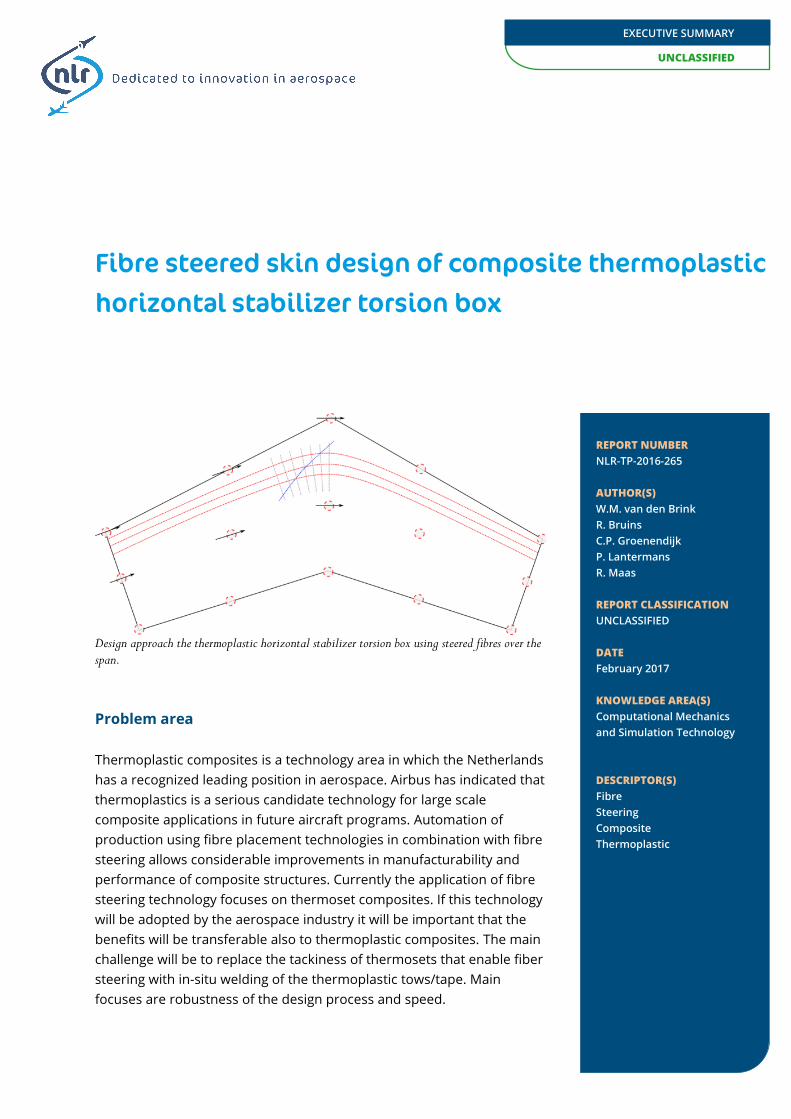
Design approach the thermoplastic horizontal stabilizer torsion box using steered fibres over the span.
Problem area
Thermoplastic composites is a technology area in which the Netherlands has a recognized leading position in aerospace. Airbus has indicated that thermoplastics is a serious candidate technology for large scale composite applications in future aircraft programs. Automation of production using fibre placement technologies in combination with fibre steering allows considerable improvements in manufacturability and performance of composite structures. Currently the application of fibre steering technology focuses on thermoset composites. If this technology will be adopted by the aerospace industry it will be important that the benefits will be transferable also to thermoplastic composites. The main challenge will be to replace the tackiness of thermosets that enable fiber steering with in-situ welding of the thermoplastic tows/tape. Main focuses are robustness of the design process and speed.
Fibre steered skin design of composite thermoplastic horizontal stabilizer torsion box
REPORT NUMBER NLR-TP-2016-265 AUTHOR(S) W.M. van den Brink R. Bruins C.P. Groenendijk P. Lantermans R. Maas REPORT CLASSIFICATION UNCLASSIFIED DATE February 2017 KNOWLEDGE AREA(S) Computational Mechanics and Simulation Technology DESCRIPTOR(S) Fibre Steering Composite Thermoplastic

UNCLASSIFIED
EXECUTIVE SUMMARY
GENERAL NOTE This report is based on a presentation held at the RaeS Aircraft Design Conference in Manchester, UK, October 4-6, 2016.
NLR
Anthony Fokkerweg 2
1059 CM Amsterdam
p ) +31 88 511 3113 f ) +31 88 511 3210
e ) [email protected] i ) www.nlr.nl
Description of work
NLR and GKN Fokker have studied the tip-to-tip fibre placement of a skin panel for a torsion box with a sweep angle. The main focus of the research was on optimizing the fibre placement speed and increase robustness of the fibre placement process. The control point fibre steering discretization approach for structural optimization of thermoplastic laminates is used together with the in-house developed PathFinder tool to define the fibre placement tow paths. Multiple load-cases are included in the global and local optimization process. For the lay-up of the torsion box skin a representation is used based on the actual ply-book including ply-drops. The upper skin laminate will be manufactured as demonstrator.
Results and conclusions
The fibre steering design optimization showed there are possibilities for improvement of the performance and weight of the design. The fibre steering has been defined in such a way that locally the laminate remain quasi isotropic with the exception of the first layer where due to a manufacturing constraint no steering could be used. The improvement in buckling load for the horizontal stabilizer torsion box with fibre steered skin was 17% compared to the conventional composite design. For the four load-cases investigated the same converged result were achieved showing the benefits of this approach. Additional analyses on global stiffness and strain distribution for the torsion box structure has been performed to assess the influence of the fibre steering. The changes to the stiffness and strain were minimal which could be caused by the local quasi isotropic laminates.
Applicability
This research of thermoplastic and fibre steering can be applied to a wide range of composite applications. The PathFinder tool is demonstrated and the importance of linking the fibre steered design to manufacturing is highlighted.

NLR - Netherlands Aerospace Centre
AUTHOR(S):
W.M. van den Brink NLR R. Bruins NLR C.P. Groenendijk R. Maas
NLR NLR
P. Lantermans Fokker GKN Aerospace
Fibre steered skin design of composite thermoplastic horizontal stabilizer torsion box
NLR-TP-2016-265 | February 2017
CUSTOMER: NLR
2
February 2017 | NLR-TP-2016-265
CUSTOMER NLR
CONTRACT NUMBER TAPAS2
OWNER NLR
DIVISION NLR Aerospace Vehicles
DISTRIBUTION Unlimited
CLASSIFICATION OF TITLE UNCLASSIFIED
APPROVED BY :
AUTHOR REVIEWER MANAGING DEPARTMENT
W.M. van den Brink W.J. Vankan A.A. ten Dam
DATE DATE DATE
This report is based on a presentation held at the RaeS Aircraft Design Conference in Manchester UK on 4 – 6 October 2016.
The contents of this report may be cited on condition that full credit is given to NLR and the author(s). This publication has been refereed by the Advisory Committee AEROSPACE VEHICLES.

3
NLR-TP-2016-265 | February 2017
Summary
Thermoplastic composites is a technology area in which the Netherlands has a recognized leading position in aerospace. Airbus has indicated that thermoplastics is a serious candidate technology for large scale composite applications in future aircraft programs. Automation of production using fibre placement technologies in combination with fibre steering allows considerable improvements in manufacturability and performance of composite structures. Currently the application of fibre steering technology focuses on thermoset composites. If this technology will be adopted by the aerospace industry it will be important that the benefits will be transferable also to thermoplastic composites. The main challenge will be to replace the tackiness of thermosets that enable fiber steering with in-situ welding of the thermoplastic tows/tape. Main focuses are robustness of the design process and speed.
NLR and GKN Fokker have studied the tip-to-tip fibre placement of a skin panel for a torsion box with a sweep angle. The main focus of the research was on optimizing the fibre placement speed and increase robustness of the fibre placement process. The control point fibre steering discretization approach for structural optimization of thermoplastic laminates is used together with the in-house developed PathFinder tool to define the fibre placement tow paths. Multiple load-cases are included in the global and local optimization process. For the lay-up of the torsion box skin a representation is used based on the actual ply-book including ply-drops . The upper skin laminate will be manufactured as demonstrator. The fibre steering design optimization showed there are possibilities for improvement of the performance and weight of the design. The fibre steering has been defined in such a way that locally the laminate remain quasi isotropic with the exception of the first layer where due to a manufacturing constraint no steering could be used. The improvement in buckling load for the horizontal stabilizer torsion box with fibre steered skin was 17% compared to the conventional composite design. For the four load-cases investigated the same converged result were achieved showing the benefits of this approach. Additional analyses on global stiffness and strain distribution for the torsion box structure has been performed to assess the influence of the fibre steering. The changes to the stiffness and strain were minimal which could be caused by the local quasi isotropic laminates. This research of thermoplastic and fibre steering can be applied to a wide range of composite applications. The PathFinder tool is demonstrated and the importance of linking the fibre steered design to manufacturing is highlighted.
4
February 2017 | NLR-TP-2016-265
This page is intentionally left blank.

5
NLR-TP-2016-265 | February 2017
Contents
Abbreviations 6
Background 8
Methodology 9
Optimization 10
Horizontal stabilizer model 11
Results 12
Optimized fibre steering result 14
Towards manufacturing using PathFinder 16
Acknowledgements 18
Conclusions and recommendations 18
References 19
6
February 2017 | NLR-TP-2016-265
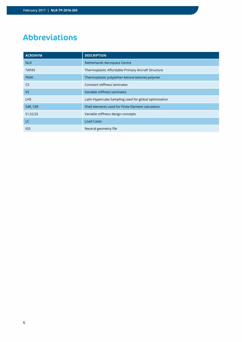
Abbreviations
ACRONYM DESCRIPTION
NLR Netherlands Aerospace Centre
TAPAS Thermoplastic Affordable Primary Aircraft Structure
PEKK Thermoplastic poly(ether-ketone-ketone) polymer
CS Constant stiffness laminates
VS Variable stiffness laminates
LHS Latin Hypercube Sampling used for global optimization
S4R, S3R Shell elements used for Finite Element calculation
S1,S2,S3 Variable stiffness design concepts
LC Load Cases
IGS Neutral geometry file

7
NLR-TP-2016-265 | February 2017
Fibre steered skin design of composite thermoplastic horizontal stabilizer torsion box
W.M. van den Brink, R. Bruins, P. Lantermans*, C. Groenendijk and R. Maas
Netherlands Aerospace Centre (NLR) * Fokker-GKN Aerospace
The Netherlands-based Thermoplastic Affordable Primary Aircraft Structure (TAPAS) consortium takes next steps in aircraft thermoplastic composites architecture. Within the TAPAS 2 programme, novel design and manufacturing approaches using thermoplastic material are investigated. Part of this work is the design of a fibre steered optimized torsion box skin for a business jet horizontal stabilizer. From previous work with fibre steering design optimization [1]. this stabilizer skin design is the next step to investigate a relevant case with multiple load-cases and manufacturing constraints in the design process. The design was made possible using the in house developed tool PathFinder. The benefits of an optimized composite skin design are defined in terms of global stabilizer stiffness and local buckling performance. The efficient optimization approach for fibre steering enables significant design freedom with a limited number of optimization parameters.[1], [3]. With the approach used for the torsion box the reference laminate definitions are maintained (with the exception of the first mould layer) which should prove beneficial for certification. Several design and manufacturing constraints are applied to reduce the rework after the optimization process. The first constraint ensures that the fibre paths for the skin are continuous over the centre-box of the stabilizer. Another constraint restricts the first layer to be non-steered and an overall minimum steering radius of 1000 mm. With thermoplastic material the fibre steering in the first layer on the mould is not feasible because of the limited tack with the metal mould. A section of the total span is investigated and manufactured with a length of around 3.0 m.
Figure 1: (left) Horizontal stabilizer location on typical aircraft. (right) Fokker’s carbon fibre-PEKK centre torsion box demonstrator for TAPAS features integrated T-stiffeners (source: Fokker Aerostructures – www.compositesworld.com).
For the design and manufacturing process a reference design is used. The reference design has been manufactured using the thermoplastic material with a fibre placement machine at NLR. The optimized design is planned to be manufactured in the near future. Open issues resulting from fibre steering are zone boundaries at different angles resulting in discontinuities in fibre angle and possibly a reduction in laminate strength [1].

8
February 2017 | NLR-TP-2016-265
Background
The basis for improved mechanical performance of composite structures lies in optimized use of the anisotropic properties of the laminate material. The use of traditional laminates with only unidirectional plies (illustrated in Figure 2) poses a strong limitation on the possibilities for laminate design. Allowing the use of variable stiffness laminates with arbitrary angles over the entire laminate the design space is significantly increased, see Figure 2.
Figure 2: (left) Illustration of composite fibre direction for a conventional constant stiffness laminate and variable stiffness laminate (middle). On the right the manufacturing of fibre steered laminates using the fibre placement manufacturing at NLR.
Variable stiffness laminates can be optimized for various applications such as bearing bypass, load changes, buckling and tailoring elastic properties (morphing structures). The focus in this paper lies on global stiffness and buckling performance of variable stiffness laminates applied on a horizontal stabilizer demonstrator, see Figure 3. In previous research on academic level the benefits of fibre steering has been shown for buckling and strength [6].
Figure 3: Example of envisaged fibre steering over the horizontal stabilizer (top view). On the right the local orientation for the 0*, 45* and 90* degree ply orientations which are used where the * indicates that the angle are initially derived from these ply orientations.
Variable stiffness laminates have been investigated for around two decades. In literature these design and optimization problems are addressed in various ways. One approach is the optimization e.g. for buckling problems, through direct variation of local fibre orientations; another approach is defining the fibre orientations on the basis of principal strains for strain resistance optimization problems. The controlled variable stiffness optimization has been extensively investigated by Gürdal and co-workers [4][5][6][7][13] showing good improvements compared to conventional laminates.
0*
45* 90*
9
NLR-TP-2016-265 | February 2017
For a common research case, buckling of a flat plate, a significant buckling load (λ) improvement ranging from 35 – 67% is shown in literature by using variable stiffness (VS) laminates compared to constant stiffness (CS) laminates. In research by Lund et. Al [10]the discrete material optimization (DMO) is used for the flat plate buckling case showing 35% improvement. In work by Setoodeh et al. [6] a generalized reciprocal approximation approach is used to define the critical buckling load using first order Taylor series expansion. In the technical report by Luraghi [11]a NURBS base-curve approach is used that uses a central curve from which parallel derivative curves are created. More recently very interesting work has been done by D. Peeters et al. [12] in the area of fibre steering in combination with topology optimization. This would allow to include automatic ply-drops in the designs. In the present study the controlled variable stiffness optimization on a ply-by-ply basis is used to optimize buckling performance. In the following section the parameterization followed by the numerical approach is described. Important aspects for application of fibre steering in aerospace are the following. Follow-up research should focus on these aspects:
• Are current laminate design rules still applicable for fibre steering designs?
• Manufacturing effect such as wrinkling and gaps/overlaps
• Certification aspects, large number of laminate definitions, damage tolerance
• Multiple load-cases, multiple reserve factors (buckling, strength)
• Weight optimization instead or performance optimization
Methodology
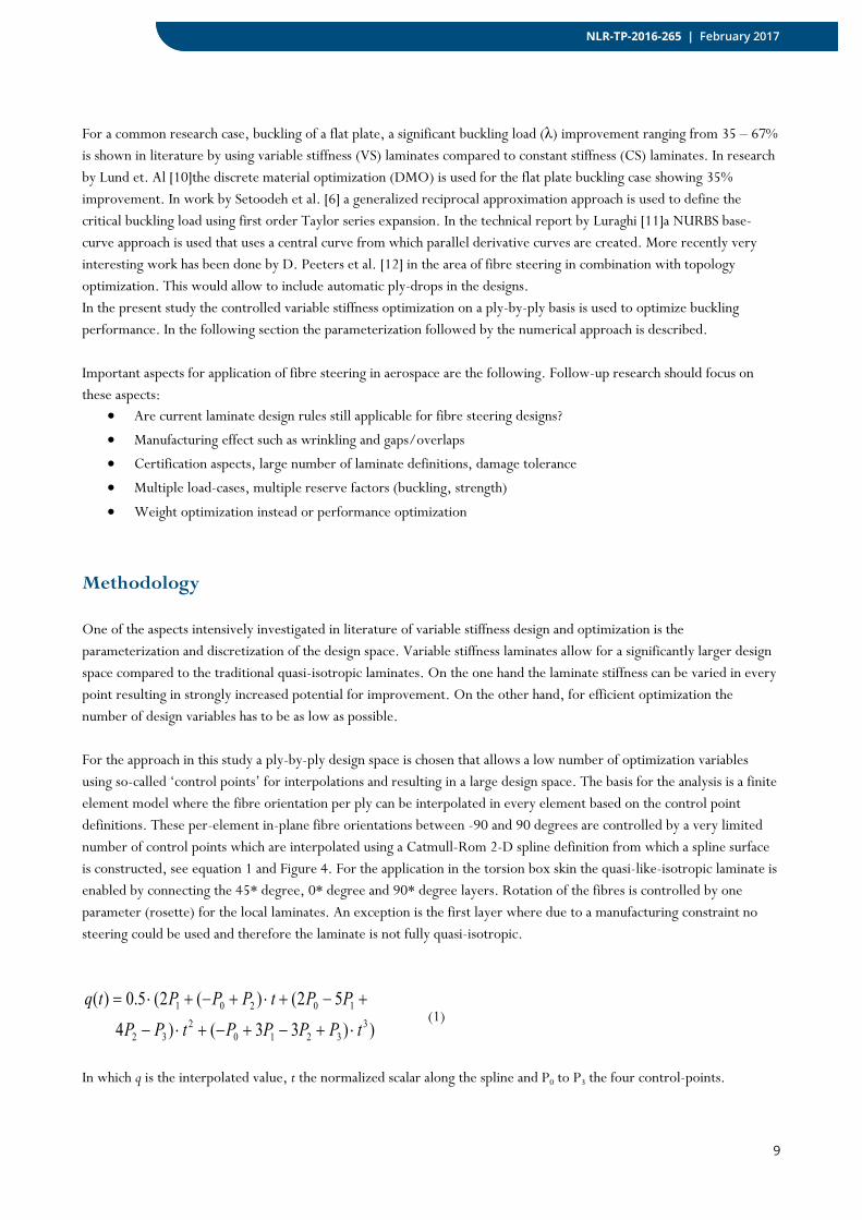
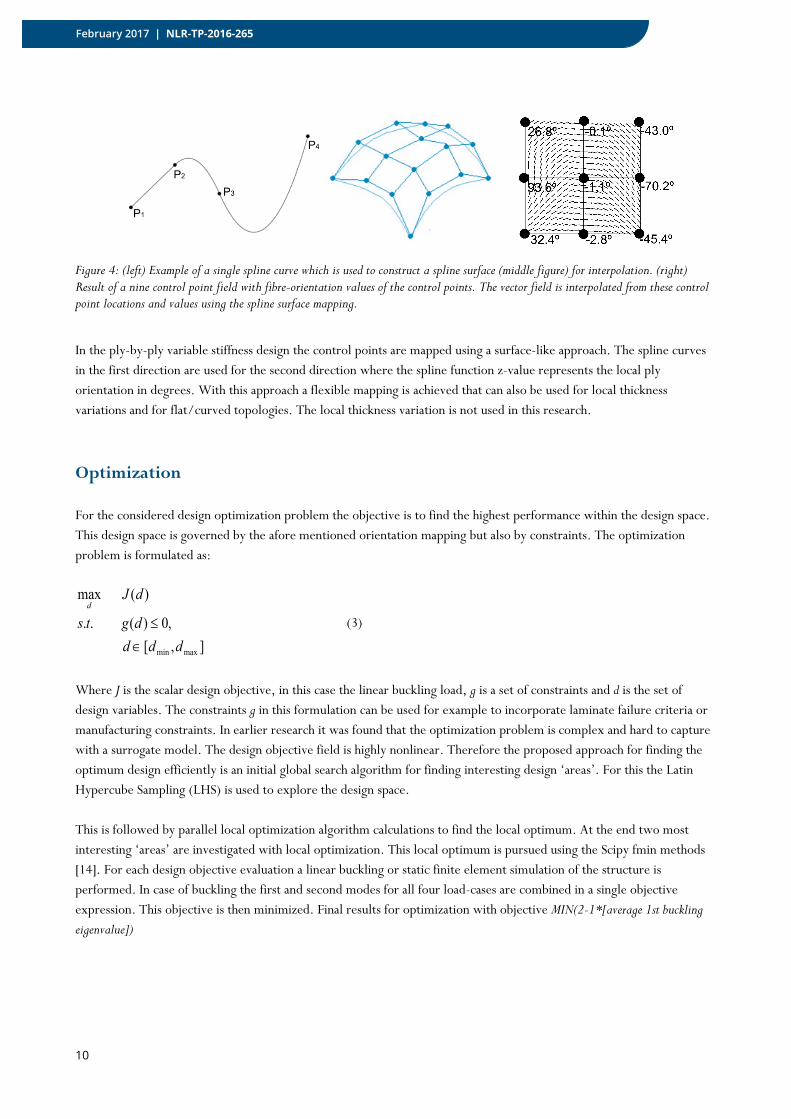
One of the aspects intensively investigated in literature of variable stiffness design and optimization is the parameterization and discretization of the design space. Variable stiffness laminates allow for a significantly larger design space compared to the traditional quasi-isotropic laminates. On the one hand the laminate stiffness can be varied in every point resulting in strongly increased potential for improvement. On the other hand, for efficient optimization the number of design variables has to be as low as possible. For the approach in this study a ply-by-ply design space is chosen that allows a low number of optimization variables using so-called ‘control points’ for interpolations and resulting in a large design space. The basis for the analysis is a finite element model where the fibre orientation per ply can be interpolated in every element based on the control point definitions. These per-element in-plane fibre orientations between -90 and 90 degrees are controlled by a very limited number of control points which are interpolated using a Catmull-Rom 2-D spline definition from which a spline surface is constructed, see equation 1 and Figure 4. For the application in the torsion box skin the quasi-like-isotropic laminate is enabled by connecting the 45* degree, 0* degree and 90* degree layers. Rotation of the fibres is controlled by one parameter (rosette) for the local laminates. An exception is the first layer where due to a manufacturing constraint no steering could be used and therefore the laminate is not fully quasi-isotropic.
))33()452()(2(5.0)(
33210
232
10201
tPPPPtPPPPtPPPtq⋅+−+−+⋅−
+−+⋅+−+⋅= (1)
In which q is the interpolated value, t the normalized scalar along the spline and P0 to P3 the four control-points.
10
February 2017 | NLR-TP-2016-265
Figure 4: (left) Example of a single spline curve which is used to construct a spline surface (middle figure) for interpolation. (right) Result of a nine control point field with fibre-orientation values of the control points. The vector field is interpolated from these control point locations and values using the spline surface mapping.
In the ply-by-ply variable stiffness design the control points are mapped using a surface-like approach. The spline curves in the first direction are used for the second direction where the spline function z-value represents the local ply orientation in degrees. With this approach a flexible mapping is achieved that can also be used for local thickness variations and for flat/curved topologies. The local thickness variation is not used in this research.
Optimization
For the considered design optimization problem the objective is to find the highest performance within the design space. This design space is governed by the afore mentioned orientation mapping but also by constraints. The optimization problem is formulated as:
],[,0)(..
)(max
maxmin ddddgts
dJd
∈≤ (3)
Where J is the scalar design objective, in this case the linear buckling load, g is a set of constraints and d is the set of design variables. The constraints g in this formulation can be used for example to incorporate laminate failure criteria or manufacturing constraints. In earlier research it was found that the optimization problem is complex and hard to capture with a surrogate model. The design objective field is highly nonlinear. Therefore the proposed approach for finding the optimum design efficiently is an initial global search algorithm for finding interesting design ‘areas’. For this the Latin Hypercube Sampling (LHS) is used to explore the design space.
This is followed by parallel local optimization algorithm calculations to find the local optimum. At the end two most interesting ‘areas’ are investigated with local optimization. This local optimum is pursued using the Scipy fmin methods [14]. For each design objective evaluation a linear buckling or static finite element simulation of the structure is performed. In case of buckling the first and second modes for all four load-cases are combined in a single objective expression. This objective is then minimized. Final results for optimization with objective MIN(2-1*[average 1st buckling eigenvalue])

11
NLR-TP-2016-265 | February 2017
Figure 5: Overview of the optimization and feedback loop. From the global opt. a selection of optima is chosen for the local optimizer. The optimum is analysed with fibre paths and feedback for model update.
Constraints included in the optimization are the lower and upper bounds of the design variables to avoid undesired designs. Furthermore, manufacturing constraints for minimal radius of fibre curvature, which are related to the operational limitations of the advanced fibre placement machine, are accounted for. This is ensured by relatively simple geometrical calculations with the distance between the control points (i.e. in which the prescribed angles are the design variables) and the relative ply orientation variation between these two control points.
Horizontal stabilizer model
Using a Nastran legacy model the basis was made for an Abaqus 6.14-1 [15] model to perform the fibre steering optimization routine. The number of control points was decided based on minimizing the computational effort but allowing enough design space for capturing the fibre steering effects. The (5x5) grid setup for the control points was chosen for this approach, see Figure 6.
Figure 6: (left) FE model and control point selection distributed over the skin section. The torsion box is fixed on the left area to the centre box section. (right) a simplified impression of the ply zoning used with different thicknesses and ply-drops.
The FE model consisted of the following elements. It is a rather coarse mesh to allow reduced computational effort for the optimization. The material used is TenCate Cetex PEKK thermoplastic composite. In Table 1 an overview of these variants is shown.
12
February 2017 | NLR-TP-2016-265
Mesh Assembly: • Total number of nodes: 4411
• Total number of elements: 4438
• 690 linear line elements of type B31
• 3563 linear quadrilateral elements of type S4R
• 185 linear triangular elements of type S3
Table 1: Overview of design models used in the study. The reference (REF) and the non-optimized fibre steered S1 and S2. The optimized fibre steering model is referred to as S3.
Design Layup Constraints Output
REF Default layup with ramp
zones upper skin
all local angles 45 difference Stiffness, buckling
S1 Steered following trailing
edge
• Rotated rosettes
• All local angles 45 difference
• 0 deg at centre box for symmetry
• First layer non-steered (135deg)
Compare stiffness, buckling
load with REF
S2 Steered following leading and
trailing edge
• Rotated rosettes
• All local angles 45 difference
• 0 deg at centre box for symmetry
• First layer non-steered (135deg)
Compare stiffness, buckling
load with REF
S3 According to LHS sampling
and optimization
• Rotated rosettes
• All local angles 45 difference
• 0 deg at centre box for symmetry
• First layer non-steered (135deg)
Compare stiffness, buckling
load with REF
In the next section the results are shown for the different designs.
Results
The finite element model as described was used to perform the analyses. The optimization was performed and fibre orientation are extracted to define the fibre paths using the PathFinder tool. In total four load-cases were investigated which were correlated with a detailed stabilizer model in Nastran. The loadcases include an upbending, downbending and gust type of loading and combinations. The resuls for the designs from Table 1 are discussed in this chapter. An example of the deflection from the four loadcases on the reference design is shown in Figure 7. For the optimization objective the local buckling was chosen since the stiffness did show a very low sensitivity to the design parameters. Local buckling occurred first in the middle area of the torsion box. However other reserve factors are calculated to determine whether the new fibre steering design satisfies the design strains (Tsai Hill), damage tolerance and stiffness. However these parameters are not actively controlled during the optimization as constraints.

13
NLR-TP-2016-265 | February 2017
Figure 7: Deflections of the torsion box reference design with the four load-cases as measure of global stiffness. As can be observed the loading induced bending and torsion in the box. Especially the bending will introduce compression loading in the stiffened panel section and cause local buckling
The non-optimized steered designs are discussed in this section. Here the fibre orientation is set by the control points at a certain values/orientation. The S1 design is non-optimized and has a smooth transition area near the centre box. The expectation was that this would improve the stiffness characteristics and local buckling behaviour. An indication of the fibre orientation of the S1 and S2 designs are shown in Figure 8.
Figure 8: (left) Non-optimized fibre steering design S1 design. The lines shown indicate the fibre orientations per element in the finite element model. It can be observed that the orientation near the centre box is vertical and transitions to the torsion box angle. (right) Typical local buckling mode observed in the stiffened panel section of the torsion box. This local buckling was optimized using the fibre steering approach.
The results for the S1 and S2 were not satisfactory with minimal improvement or even lower global stiffness. The buckling performance was slightly improved by ~1%. Therefore the optimization process for the S3 design was started to enable more control over the design parameters.

14
February 2017 | NLR-TP-2016-265
Optimized fibre steering result
During the optimization it was observed that the influence of the global stiffness from fibre steering was minimal. This was possibly caused by the rotation of the laminate rosette (quasi-like-isotropic locally) which did not result in large changes in stiffness. Therefore a focus was made on local buckling performance improvement. Here a significant increase has been achieved for all load-cases. The global optimization based on LHS analyses gave results for five starting points for the local optimization. At this point no significant improvement was observed for buckling onset. The local optimization further improved the local buckling behaviour of the torsion box using the fibre steering. The results after the optimization and reference designs are shown in Table 2 and Table 3. Table 2: Result of the torsion box skin fibre steering optimization. The four load-cases LC1 – LC4 are indicated. The global stiffness which is defined as displacement of the tip in [mm] is indicated in the table. The results show for the S3 a reduction in stiffness.
Design LC1 LC2 LC3 LC4 Average
Reference 156.0 120.0 116.0 141.0 133.0
S1 157.0 121.0 117.0 142.0 134.0 S1 difference (-1/%Δ)
-1.6 -1.2 -1.2 -1.4 -1.3
S2 156.0 120.0 116.0 141.0 133.0 S2difference (-1/%Δ)
0.0 0.0 0.0 0.0 0.0
S3 (opt.) 159.0 121.0 119.0 144.0 136.0 S3 difference (-1/%Δ)
-0.5 -1.2 -0.4 -0.5 -0.5
Table 3: Result of the torsion box skin fibre steering optimization. The four load-cases LC1 – LC4 are indicated. The buckling behaviour with the first and second buckling modes are indicated in the table. The results show for the S3 an increase of the average buckling modes of 17%.
Design LC1 LC2 LC3 LC4 Average
1st
mode 2nd
mode 1st
mode 2nd
mode 1st
mode 2nd
mode 1st
mode 2nd
mode 1st mode 2nd mode
Reference -0.839 -0.862 1.065 1.084 1.136 1.170 -0.985 -1.013 1.006 1.032
S1 -0.844 -0.865 1.066 1.087 1.144 1.175 -0.992 -1.018 1.012 1.036
Δ ref (%) 0.6 0.3 0.1 0.3 0.7 0.4 0.7 0.5 0.5 0.4
S2 -0.844 -0.865 1.069 1.090 1.142 1.173 -0.990 -1.015 1.011 1.036
Δ ref (%) 0.6 0.3 0.4 0.6 0.5 0.3 0.5 0.2 0.5 0.3
S3 (opt.) -0.968 -0.989 1.262 1.290 1.340 1.386 -1.167 -1.208 1.184 1.218
Δ ref (%) 15.4 14.8 18.5 19.0 17.9 18.4 18.4 19.2 17.7 18.0
The S3 design results clearly show an improvement of buckling load factor for all four load-cases. In general the location of first buckling and number of modes did not change significantly. From the fibre steering orientations it was observed
15
NLR-TP-2016-265 | February 2017
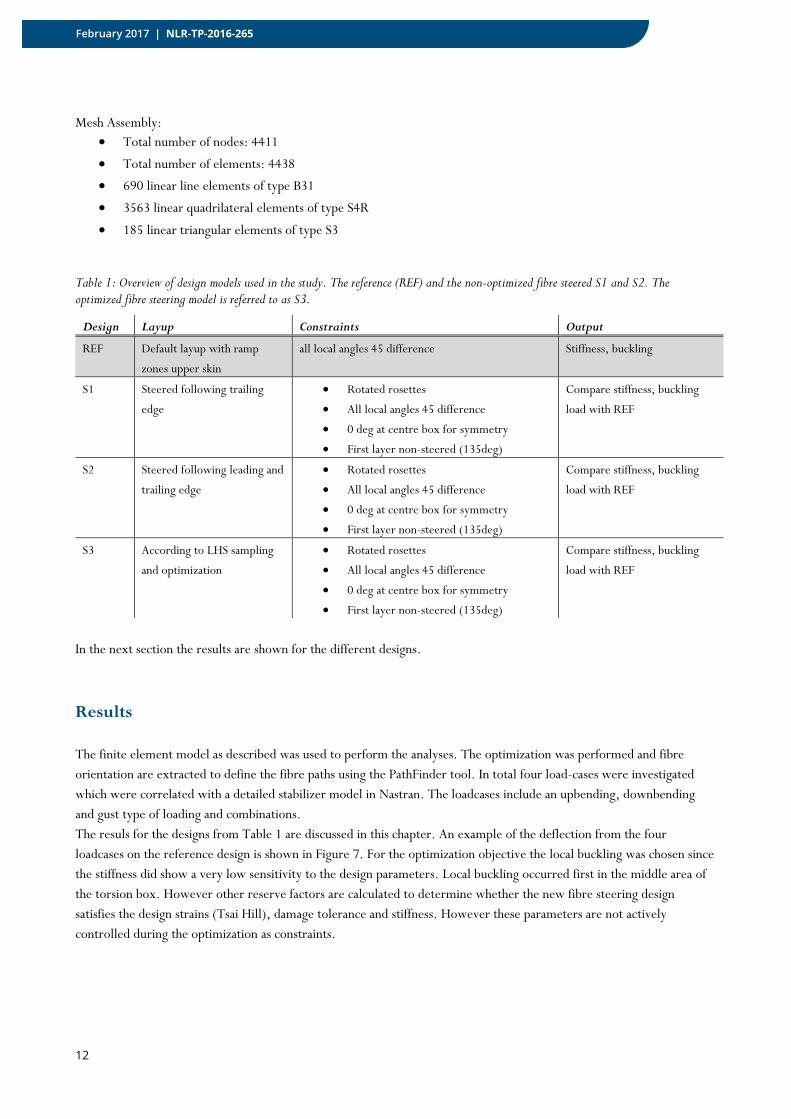
that in the area of first buckling the 0* and 90* plies were creating a 45 degree rotation. However a clear explanation for the improved buckling performance cannot be given although load transfer to other areas of the skin is suspected. The resulting fibre steering design for S3 shows a curvature from edge to middle section. Because of the distribution of control points the change in orientation over the skin is relative small, see Figure 9.
Figure 9: Fibre steered ply design for the optimized S3 variant. (left) the 0* full plies, (middle) the 45* plies and (right) the 90* plies. At local level all orientations are based on 0/45/-45/90 degree laminates definitions.
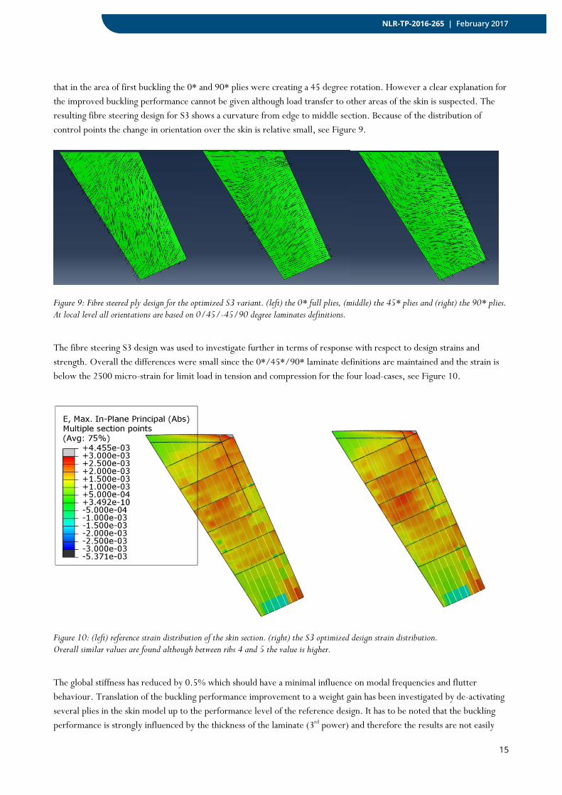
The fibre steering S3 design was used to investigate further in terms of response with respect to design strains and strength. Overall the differences were small since the 0*/45*/90* laminate definitions are maintained and the strain is below the 2500 micro-strain for limit load in tension and compression for the four load-cases, see Figure 10.
Figure 10: (left) reference strain distribution of the skin section. (right) the S3 optimized design strain distribution. Overall similar values are found although between ribs 4 and 5 the value is higher.
The global stiffness has reduced by 0.5% which should have a minimal influence on modal frequencies and flutter behaviour. Translation of the buckling performance improvement to a weight gain has been investigated by de-activating several plies in the skin model up to the performance level of the reference design. It has to be noted that the buckling performance is strongly influenced by the thickness of the laminate (3rd power) and therefore the results are not easily
16
February 2017 | NLR-TP-2016-265
converted to a weight saving. An investigative research into weight gain showed that a reduction of several selected plies results in around 960 g weight reduction which translates 1.2% weight reduction for the analysed component and 3% weight reduction for the skin section only. For this weight estimation no local effects such as gaps and overlaps of the fibre placement are included. The estimated weight gain is relatively small compared to the buckling performance gain. This is a theoretical result based on the vector field orientations and not including the fibre path orientations.
Towards manufacturing using PathFinder
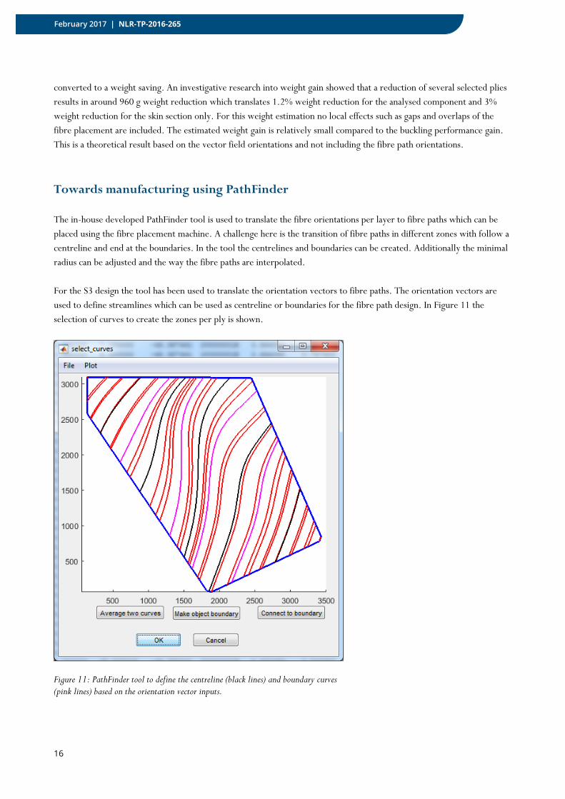
The in-house developed PathFinder tool is used to translate the fibre orientations per layer to fibre paths which can be placed using the fibre placement machine. A challenge here is the transition of fibre paths in different zones with follow a centreline and end at the boundaries. In the tool the centrelines and boundaries can be created. Additionally the minimal radius can be adjusted and the way the fibre paths are interpolated. For the S3 design the tool has been used to translate the orientation vectors to fibre paths. The orientation vectors are used to define streamlines which can be used as centreline or boundaries for the fibre path design. In Figure 11 the selection of curves to create the zones per ply is shown.
Figure 11: PathFinder tool to define the centreline (black lines) and boundary curves (pink lines) based on the orientation vector inputs.
17
NLR-TP-2016-265 | February 2017
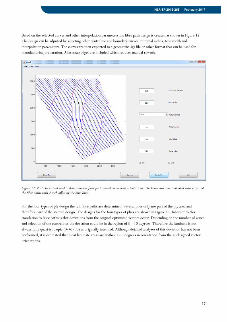
Based on the selected curves and other interpolation parameters the fibre path design is created as shown in Figure 12. The design can be adjusted by selecting other centreline and boundary curves, minimal radius, tow width and interpolation parameters. The curves are then exported to a geometric .igs file or other format that can be used for manufacturing preparation. Also scrap edges are included which reduces manual rework.
Figure 12: PathFinder tool used to determine the fibre paths based on element orientations. The boundaries are indicated with pink and the fibre paths with 2 inch offset by the blue lines.
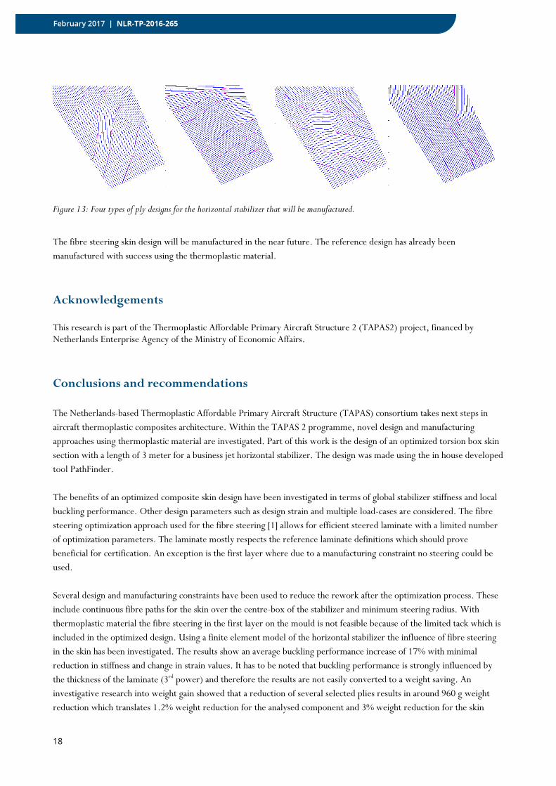
For the four types of ply design the full fibre paths are determined. Several plies only use part of the ply area and therefore part of the steered design. The designs for the four types of plies are shown in Figure 13. Inherent to this translation to fibre paths is that deviations from the original optimized vectors occur. Depending on the number of zones and selection of the centrelines the deviation could be in the region of 5 – 10 degrees. Therefore the laminate is not always fully quasi-isotropic (0/45/90) as originally intended. Although detailed analyses of this deviation has not been performed, it is estimated that most laminate areas are within 0 – 5 degrees in orientation from the as-designed vector orientations.
18
February 2017 | NLR-TP-2016-265
Figure 13: Four types of ply designs for the horizontal stabilizer that will be manufactured.
The fibre steering skin design will be manufactured in the near future. The reference design has already been manufactured with success using the thermoplastic material.
Acknowledgements
This research is part of the Thermoplastic Affordable Primary Aircraft Structure 2 (TAPAS2) project, financed by Netherlands Enterprise Agency of the Ministry of Economic Affairs.
Conclusions and recommendations
The Netherlands-based Thermoplastic Affordable Primary Aircraft Structure (TAPAS) consortium takes next steps in aircraft thermoplastic composites architecture. Within the TAPAS 2 programme, novel design and manufacturing approaches using thermoplastic material are investigated. Part of this work is the design of an optimized torsion box skin section with a length of 3 meter for a business jet horizontal stabilizer. The design was made using the in house developed tool PathFinder. The benefits of an optimized composite skin design have been investigated in terms of global stabilizer stiffness and local buckling performance. Other design parameters such as design strain and multiple load-cases are considered. The fibre steering optimization approach used for the fibre steering [1] allows for efficient steered laminate with a limited number of optimization parameters. The laminate mostly respects the reference laminate definitions which should prove beneficial for certification. An exception is the first layer where due to a manufacturing constraint no steering could be used. Several design and manufacturing constraints have been used to reduce the rework after the optimization process. These include continuous fibre paths for the skin over the centre-box of the stabilizer and minimum steering radius. With thermoplastic material the fibre steering in the first layer on the mould is not feasible because of the limited tack which is included in the optimized design. Using a finite element model of the horizontal stabilizer the influence of fibre steering in the skin has been investigated. The results show an average buckling performance increase of 17% with minimal reduction in stiffness and change in strain values. It has to be noted that buckling performance is strongly influenced by the thickness of the laminate (3rd power) and therefore the results are not easily converted to a weight saving. An investigative research into weight gain showed that a reduction of several selected plies results in around 960 g weight reduction which translates 1.2% weight reduction for the analysed component and 3% weight reduction for the skin
19
NLR-TP-2016-265 | February 2017
section only. For this weight estimation no local effects such as gaps and overlaps of the fibre placement are included. The estimated weight gain is relatively small compared to the buckling performance gain. This is a theoretical result based on the vector field orientations and not including the fibre path orientations. Further research is needed to enable robust and efficient optimization using fibre steering to reduce weight of aircraft components. Although this study has shown some benefits of using fibre steering in terms of performance, the weight benefits are small. Furthermore the certification of these types of aircraft structures would require more testing and understanding of manufacturing effects such as wrinkling and gaps introduced by fibre steering designs.
References
[1] F. Heinecke, W.M.van den Brink, T. Wille, Assessing the structural response of automated fibre placement composite structures with gaps and overlaps by means of numerical approaches, NLR-TP-2015-242, presented at the ICCS20, Copenhagen
[2] W.M. van den Brink, W.J. Vankan, R. Maas, Buckling-optimized variable stiffness laminates for a composite fuselage window section, ICAS 2012 conference, Brisbane, Australia
[3] W.J. Vankan, W.M. van den Brink, R. Maas and M. Nawijn, Aircraft composite fuselage optimization through barrel and panel level analyses, ECCOMAS Composites 2011, Hannover, Germany, 21-23 September 2011.
[4] Z. Gürdal and R. Olmedo, In-plane response of laminates with spatially varying fibre orientations: Variable stiffness concept, AIAA J., 31(4), pp. 751–758, 1993.
[5] Alhajahmad, M.M. Abdalla and Z. Gürdal, Design tailoring for pressure pillowing using tow-placed steered fibers, J. Aircraft, 45(2), pp. 630-640, 2008.
[6] S. Setoodeh, M.M. Abdalla and Z.Gürdal, Design of variable stiffness laminates using lamination parameters, Composites, Part B: Engineering, 37, pp. 301-309, 2006.
[7] A.W. Blom, M.M. Abdalla and Z. Gürdal, Optimization of Course Locations in Fiber-Placed Panels for General Fiber Angle Distributions, J. Compos. Sc. Technol., 70(4), pp. 564-570, 2010.
[8] Nelder, J.A. and Mead, R. (1965), “A simplex method for function minimization”, The Computer Journal, 7, pp. 308-313 Wright, M.H. (1996), “Direct Search Methods: Once Scorned, Now Respectable”, in Numerical Analysis 1995, Proceedings of the 1995 Dundee Biennial Conference in Numerical Analysis, D.F. Griffiths and G.A. Watson (Eds.), Addison Wesley Longman, Harlow, UK, pp. 191-208.
[9] Catmull, E., and Rom, R. A class of local interpolating splines. In Computer Aided Geometric Design, R. E. Barnhill and R. F. Reisenfeld, Eds. Academic Press, New York, 1974, pp. 317–326.
[10] Lund E, Kuhlmeier L, Stegmann J. Buckling optimization of laminated hybrid composite shell structures using discrete material optimization. In: 6th World Congress on Structural and Multidisciplinary Optimization, Rio de Janeiro, June 2005.
[11] F. Luraghi, Surrogate Model-Based Design Optimization of Variable-Stiffness Composite Panels, Technical report, ONERA, 2011
[12] D. Peeters, D. van Baalen, M. Abdalla (2014) “Combining topology and lamination parameter optimisation”, Conference Paper, SciTech 2014
[13] C. Kassapoglou, Design and Analysis of Composite structures: with applications of aerospace structures, 2011 [14] Scipy fmin optimizer, website for documentation:
http://docs.scipy.org/doc/scipy/reference/generated/scipy.optimize.fmin.html [15] Abaqus 6.14-1 finite element software

20
February 2017 | NLR-TP-2016-265
This page is intentionally left blank.


NLR
Anthony Fokkerweg 2 1059 CM Amsterdam, The Netherlands p ) +31 88 511 3113 f ) +31 88 511 3210 e ) [email protected] i ) www.nlr.nl