field installation manual for hybrid-â€composite beams
TRANSCRIPT

H C B , I n c 1 5 2 1 L a k e A v e n u e W i l m e t t e , I l l i n o i s 6 0 0 9 1 w w w . H C B r i d g e . c o m
Field Installation Manual for Hybrid-‐Composite Beams

FIELD INSTALLATION MANUAL FOR HYBRID COMPOSITE BEAMS
1
Introduction The Hybrid Composite Beam (HCB®) was invented in the mid-‐1990’s by acclaimed bridge engineer, Mr. John Hillman, PE. One of the goals in the development of the HCB was to provide a beam that contractors would be able to erect and complete a structure using everyday techniques and equipment. Since the first bridge in 2007, contractors and owners have consistently been delighted with the ease of installing an HCB structure. This manual describes the methods and equipment needed to install an HCB structure. As you read through it, you will see very familiar and common techniques and equipment. If you do have any questions about building a structure with HCB’s, please contact our staff.

FIELD INSTALLATION MANUAL FOR HYBRID COMPOSITE BEAMS
2
What is an HCB®?
Components The HCB is the result of several components acting together as a tied arch to form an efficient structural member. The main components are:
• Tension Reinforcement – this usually consists of galvanized prestressing
strand. • Compression Reinforcement – this is the arch profile that is filled with self-‐
consolidating concrete • Fiber-‐Reinforced Polymer Shell (FRP) – this holds the tension and
compression reinforcement and creates a corrosion resistant beam. The shell may also have flanges that act as deck forms.
• Shear Connectors – these are usually galvanized rebars that tie the beam to the concrete deck as any conventional prestressed or steel beam structure.
The diagram below provides a schematic of these components.
How it Works HCB’s work as a tied a tied arch system. When a beam is fabricated, the required tension reinforcement is “infused” into the bottom flange of the FRP shell. Once the shells are filled with concrete, the beam acts similar to a reinforced concrete beam. A load is placed on the beam, the load is then transferred to the compression reinforcement (concrete arch) that tends to push the arch out at it ends. This force
What is the HCB? �Tied Arch in A Fiberglass Box� A structural member using several different building materials resulting in a cost effective composite beam designed to be stronger, lighter, and more corrosion resistant ! Compression Arch - SCC Concrete ! Tension Reinforcement - Galvanized P/S Strand - Fiberglass Cloth ! FRP Shell ! Galvanized Shear Connectors
Tension Reinforcement - Galvanized P/S Strand - Fiberglass Cloth
FRP Shell
Compression Arch
Shear Connectors
FIELD INSTALLATION MANUAL FOR HYBRID COMPOSITE BEAMS
3
is equilibrated by the tension reinforcement in the bottom flange keeping the arch from being able to move outward. If the beam is composite with the deck, the deck also acts as a compression flange to balance the tension in the bottom flange as in a conventional structure. Characteristics of HCB’s and their components.
• FRP’s are very strong, resilient and flexible. The can be handled with slings or cables and won’t spall like concrete or deform like a steel beam flange.
• While prestressing strands are used, they are not prestressed in the traditional manner. The only prestress in the strands is due to the placement of the compression reinforcement and concrete deck.
• Since FRP’s are flexible, it can be difficult for an FRP alone to meet the deflection requirements of the bridge codes. Usually half of the prestressing strands in the bottom flange are to provide the required stiffness for the structure.
• Empty shells are strong and can be picked at the mid-‐point without damage. Since they are lightweight, contractors have removed the beams from the delivery trucks with forklifts and set them subsequently with a small rough terrain crane that was already on site for the substructure.

FIELD INSTALLATION MANUAL FOR HYBRID COMPOSITE BEAMS
4
Erecting HCB’s There are three HCB configurations and this section will discuss the installation considerations for each one. They are
• Empty beam shells filled in place • Prefilled beam shells
• Prefabricated bridge modules
Empty Shells Filled in Place To date, the most common method for constructing a structure using HCB’s is to set the shells empty, fill them with self-‐consolidating concrete and then form and cast a deck. This method provides the advantage of shipping and setting an extremely lightweight piece (a typical 70 ft beams weighs 4,500 lbs).
Handling and Setting an Empty HCB Empty HCB’s can be handled using slings, cables or forks underneath at the mid-‐point. While the limitations on picking locations are few, they need to be observed.
1. No matter what method of picking is used, make sure the empty shell is not filled with water. While HCB’s are manufactured with drain holes in each end, they could become plugged during storage or transport. The weight of water inside a beam can more than double its weight.
2. While lifting a beam at the midspan is theoretically possible, HCB
recommends lifting the beam in accordance with the approved shop drawings. The picking points should be spread equally about the

FIELD INSTALLATION MANUAL FOR HYBRID COMPOSITE BEAMS
5
longitudinal midpoint of the beam and be far enough apart to prevent the beam from either tipping off forks or sliding through straps.
3. Square edges of FRP’s can be sharp enough to cut into a nylon strap, always use a softener anywhere a nylon strap contacts a square edge.
4. There are no lifting devices provided on empty shells unless they are specifically requested and shown on the approved shop drawings.
When the beams arrive on site, they can be easily off-‐loaded with a fork truck beneath the beam or with equipment (excavator, fork truck or crane) and set on dunnage for storage and or preparation for setting in place. To set beams in place, either from storage or directly from the delivery vehicle, ensure the pick points, centerline of bearing and center of beam are properly marked. Pick the beam as shown on the approved erection plan (if required) using nylon straps or steel cables. Set the beam in position using the marks. Note that beams may easily be shifted using bars once they are set on the substructure due to their lightweight. Once set in place, secure the beam to the substructure and/or adjacent beams and repeat the process for all the beams.

FIELD INSTALLATION MANUAL FOR HYBRID COMPOSITE BEAMS
6
Filling an HCB in place HCB’s filled in place are done primarily by two methods, either by gravity feed using a hopper or a concrete pump at low pressure. In either method, a self-‐consolidating concrete is used with a spread in the range of 26” to 30” and a maximum 3/8” aggregate size. Because the areas of interior of an HCB that form the arch are filled with a polyisocyanurate foam, the heat retention is very high. Therefore the concrete mix should have enough set retarding admixture to provide a 3 to 5 hour working time. This prevents a flash set inside the beam that could create a cold joint. HCB’s are filled using 4” diameter holes spread throughout the length of the beam. The spacing of the holes is a function of the length, depth and anticipated temperature. Your HCB representative will work with you to provide the fill hole spacing.
Using a concrete pump – the concrete pump must be capable of reaching each end of the beam. HCB’s can not be filled by pressure grouting the way a post-‐tensioning tendon would. The typical procedure starts at one end, progresses to the hole nearest to midspan, then goes to the other end and works back to the middle. The beam is topped off as necessary at any hole once the beam has been mostly filled. The pump should either empty into a hopper or into a flexible coupling that is inserted into the fill hole. Rigidly connecting the pump hose to the beam is not
FIELD INSTALLATION MANUAL FOR HYBRID COMPOSITE BEAMS
7
recommended. Pump pressures should be kept very low to allow the SCC to move along the length of the beam without backing up or causing the sidewalls of the beam to flex out. The beam is full when concrete is seen out of every hole in the top of the beam (shear connectors, fill holes, etc.). Secondary holes, usually 2” diameter can be put into the top flange to facilitate the placement of a vibrator to maintain plastic flow of concrete. Never begin to fill a beam unless enough concrete is on-‐site to completely fill one beam unless otherwise allowed by the owner’s representative on-‐site.
Prefiled HCB’s A second option for installing HCB’s is to “prefill” them somewhere other than their final position. This can be done at the FRP fabricator, a precast concrete facility, other off-‐site location or at the jobsite. The advantages of a prefilled beam are that it can be filled at or near the source of concrete, may be directly filled from a ready-‐mix truck and once set in place is ready for deck reinforcement. While the additional weight may be an issue in transporting and erection, due to the efficient use of concrete, HCB’s are still very light even when prefilled.
Preparing and prefilling an HCB The procedure for prefilling an HCB is very similar to filling an HCB in place. The beams are transported to the prefill location and set on wooden or other suitable dunnage at the centerline of bearing. The procedure for transporting and setting the empty shells for prefilling is the same as described above. The beams are then prepared for filling in the same manner described above with the additional step of installing suitable lifting devices (usually prestressed strand lifting loops). The beams are then filled in the same manner as the in place beams, except access is better.
Transporting Filled HCB’s Prefilled HCB’s must be transported at or near the centerline of bearing on each end in a similar manner to prestressed concrete girders. If the beams are to be transported supported with a large overhang, the engineer must determine what, if any additional materials must be included in the FRP shell or compression reinforcement to withstand the transportation loads.

FIELD INSTALLATION MANUAL FOR HYBRID COMPOSITE BEAMS
8
Erecting Filled HCB’s Prefilled HCB’s must be handled using the lifting loops cast into the beam or straps at or near the centerline of bearing . Good rigging practices must be followed and the sling angle must not subject the lifting device to any forces for which it is not designed. As with any structural member, as each beam is set it must be secured with an appropriate form of temporary bracing until the deck is cast.
Deck Forming Forming of reinforced concrete decks follows the same procedures as it would for prestressed concrete or steel beams. SIP deck forms, Prestressed Concrete Planks for deck forms, wooden or removable forms, etc. can all be used based on the project and owner requirements. Cross-‐slope, superelevation, vertical curves are all accommodated in the same way as other conventional forms of construction.
Adjacent Beams When HCB’s are set adjacent to each other, they are normally set with the top of the beam perpendicular to the cross slope, similar to prestressed box beams or voided slabs. In these instances, there is usually a ½” to 1” gap between the flanges of the beams which allow for fabrication and erection tolerances. The use of a commercially available self-‐adhering flashing tape to span the joint allows the beams deflect differentially due to the plastic concrete being placed for the deck.
Spread Beams Spread HCB’s may or may not have integral flanges and are normally set plumb. In addition, the beams are usually set at an elevation on individual bearing seats corresponding to the cross-‐slope of the deck. The deck forming requirements of the owner will determine the actual materials to form the deck. This section will cover some of the more common methods. Prestressed Concrete Planks – these SIP type forms are set on a preformed joint material that is placed on each edge of the top flange. The height of the joint filler is determined by surveying the beam for actual camber (after the compression arch of the beam is filled) and determining the required joint filler height based on the

FIELD INSTALLATION MANUAL FOR HYBRID COMPOSITE BEAMS
9
calculated deflection for the required deck elevation and thickness. This is the same as concrete or steel beams. Note that due to the weight of these forms they must be placed on filled beams. HCB advises against using prestressed concrete plank forms with the integral flanges. SIP Steel or FRP Deck Forms – Once the beams have been filled, the beams are surveyed for camber and the deck forms attached at the appropriate height using a joint filler or support angle. While these forms can be set on empty beams, the must have the capability of being adjusted after the beams are filled with concrete due to variations in camber. Removable Deck Forms – These are usually wooden forms that can be removed after deck placement. Typical half or full hangers can be embedded into the beam or attached to the shear connectors. Another option is a joist hanger system from the top flange. As with the other two types of forming systems, the hangers and deck forms should be set after surveying the beams after filling the compression arch.
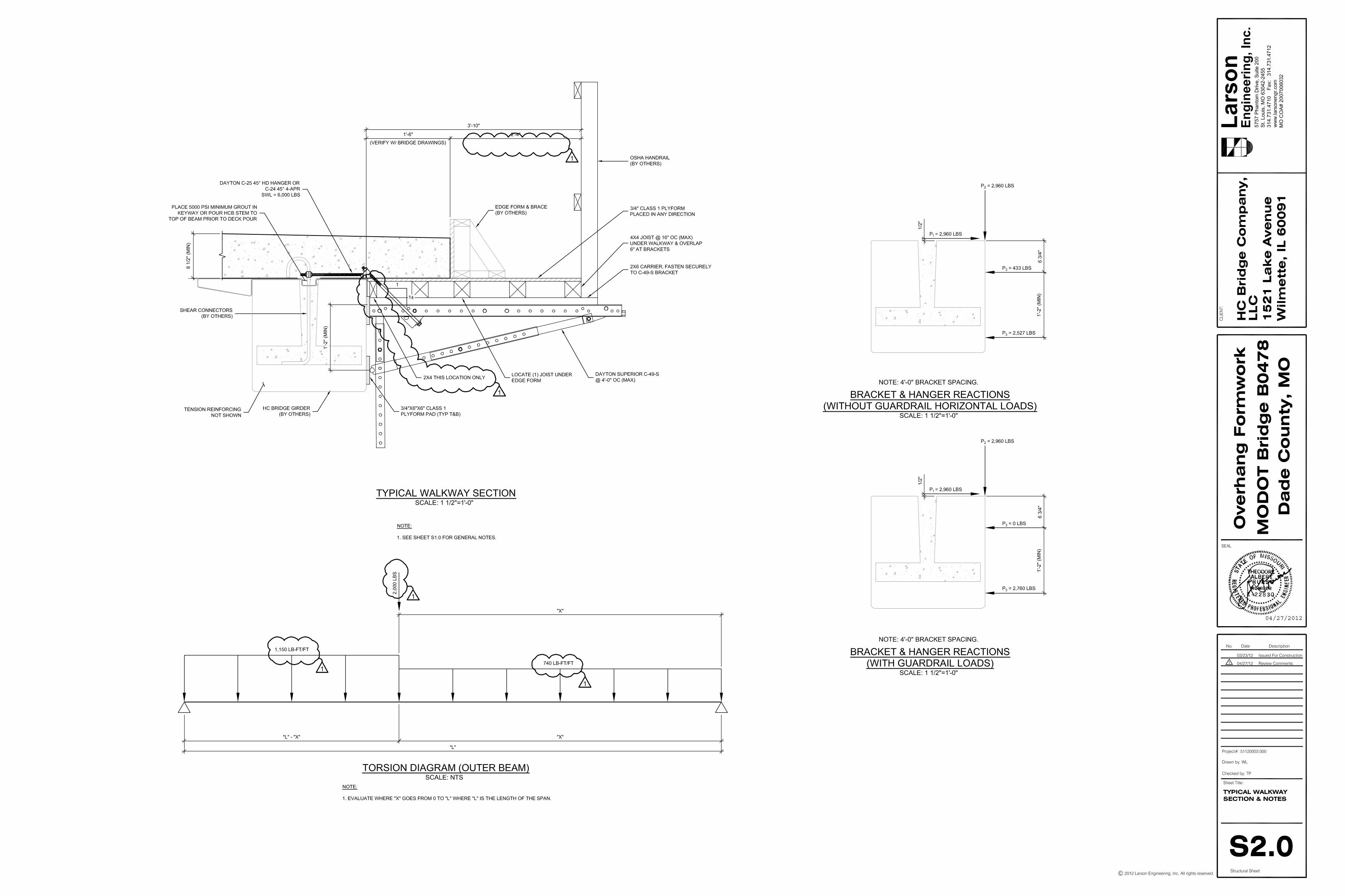
Overhangs Deck overhangs can be accomplished with either an integral form to the HCB or a traditional overhang bracked and formed wood deck. If the bridge has been designed with the top flange of the beam extending out to the edge of the deck, a composite angle can be glued to the top flange and side forms attached. Conversely, overhang brackets and a walkway can be attached to the beams by drilling through the top flange. If the beam flange does not extend to the edge of deck, traditional deck forming system using commercially available hangers and overhang brackets can be used. While the deck can be formed with this method, we recommend not installing brackets or forms until the beams are filled. Careful attention must be paid to the weight of the cantilevered form wanting to overturn the lightweight beam and it must be braced accordingly.
FIELD INSTALLATION MANUAL FOR HYBRID COMPOSITE BEAMS
10
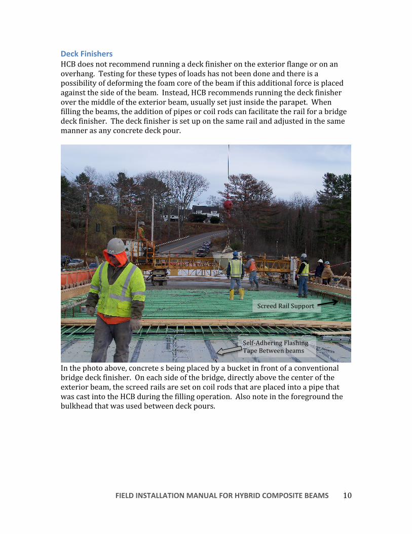
Deck Finishers HCB does not recommend running a deck finisher on the exterior flange or on an overhang. Testing for these types of loads has not been done and there is a possibility of deforming the foam core of the beam if this additional force is placed against the side of the beam. Instead, HCB recommends running the deck finisher over the middle of the exterior beam, usually set just inside the parapet. When filling the beams, the addition of pipes or coil rods can facilitate the rail for a bridge deck finisher. The deck finisher is set up on the same rail and adjusted in the same manner as any concrete deck pour.
In the photo above, concrete s being placed by a bucket in front of a conventional bridge deck finisher. On each side of the bridge, directly above the center of the exterior beam, the screed rails are set on coil rods that are placed into a pipe that was cast into the HCB during the filling operation. Also note in the foreground the bulkhead that was used between deck pours.
Self-‐Adhering Flashing Tape Between beams
Screed Rail Support
FIELD INSTALLATION MANUAL FOR HYBRID COMPOSITE BEAMS
11
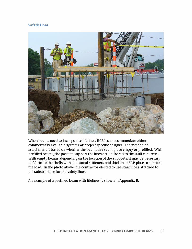
Safety Lines
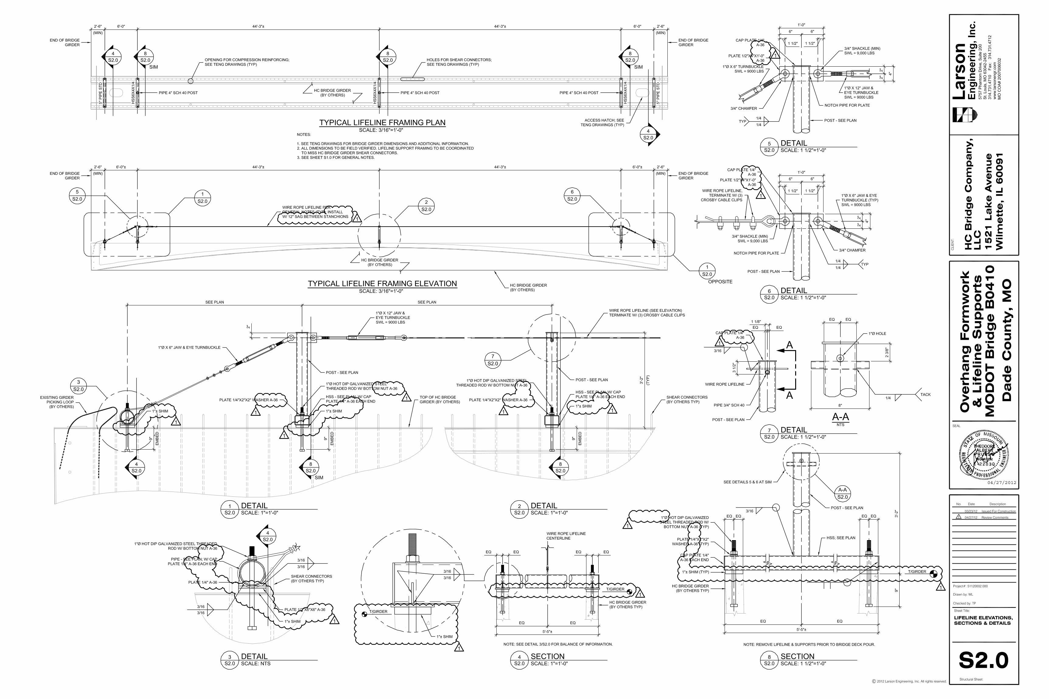
When beams need to incorporate lifelines, HCB’s can accommodate either commercially available systems or project specific designs. The method of attachment is based on whether the beams are set in place empty or prefilled. With prefilled beams, the posts to support the lines are anchored to the infill concrete. With empty beams, depending on the location of the supports, it may be necessary to fabricate the shells with additional stiffeners and thickened FRP plate to support the load. In the photo above, the contractor elected to use stanchions attached to the substructure for the safety lines. An example of a prefilled beam with lifelines is shown in Appendix B.
FIELD INSTALLATION MANUAL FOR HYBRID COMPOSITE BEAMS
12
Appurtenances
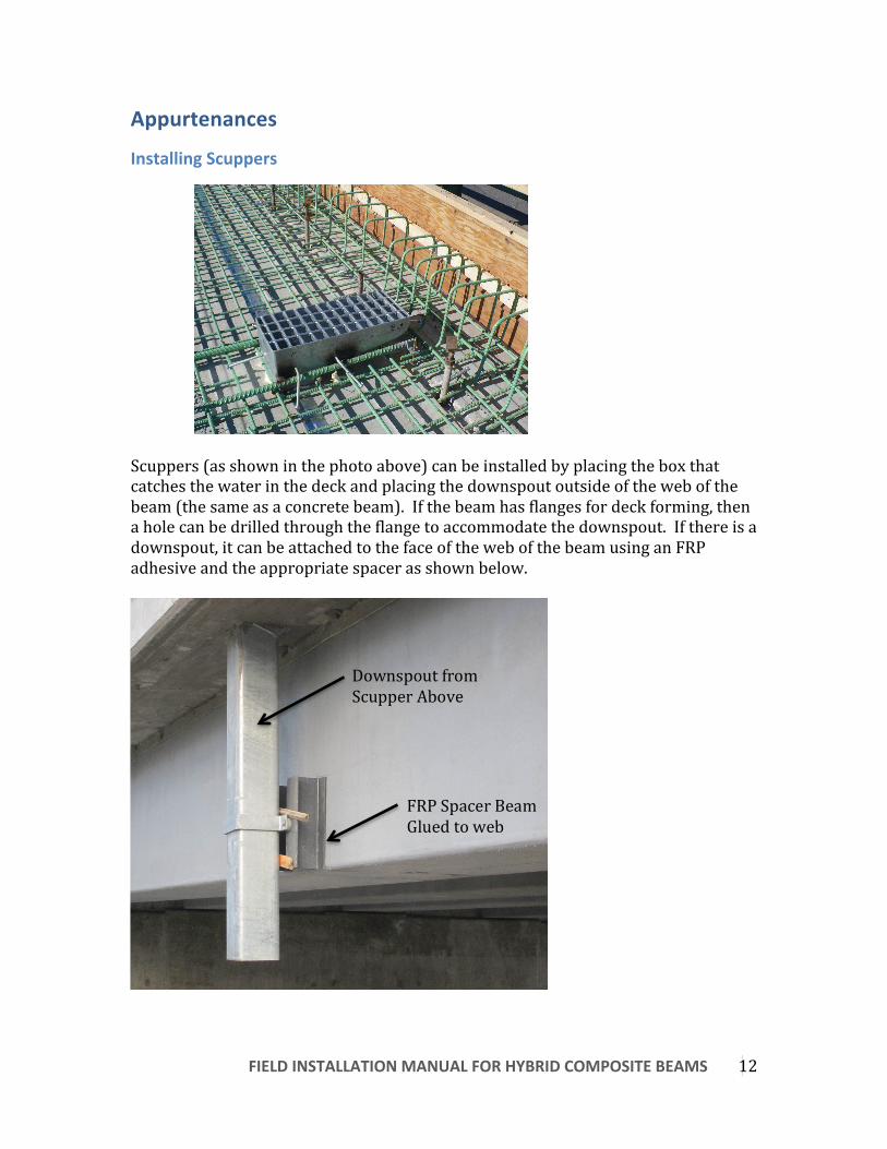
Installing Scuppers
Scuppers (as shown in the photo above) can be installed by placing the box that catches the water in the deck and placing the downspout outside of the web of the beam (the same as a concrete beam). If the beam has flanges for deck forming, then a hole can be drilled through the flange to accommodate the downspout. If there is a downspout, it can be attached to the face of the web of the beam using an FRP adhesive and the appropriate spacer as shown below.
Downspout from Scupper Above
FRP Spacer Beam Glued to web

FIELD INSTALLATION MANUAL FOR HYBRID COMPOSITE BEAMS
13
Railings, Parapets and Lighting Railing, Parapets and Lighting are normally connected to the bridge deck and not the beam. Therefore, the same is true for an HCB Bridge, these items are directly connected to the concrete deck. Utility Hangers Utility hangers for pipes and conduits are normally installed such that they do not have to be removed during deck replacement. This means some type of support spanning from beam to beam or directly affixing to the web. HCB does not recommend direct fixation to the web as the sole means of support with the Hybrid-‐Composite Beam. Instead, a beam, angle, structural tubing, etc. spanning between the beams and fully encapsulated in the deck with hanger rods is the best option. If needed, the utility hanger can have keeper blocks attached to the web with an FRP adhesive to prevent movement of the hanger and utilities. An added benefit of the HCB, is its insulating properties from the foam. By placing a water line between the beams and a small panel between the bottom of the webs, it may prevent the need to run any type of heat trace along a water line in colder climates.

Appendix A
Bridge B0478, Missouri DOT Note: The drawings and engineering design shown in this Appendix relate to a specific bridge and do not represent a general design for deck forming, overhangs, erection procedures, etc. They are shown as an example from a previous project.

04/27/2012
04/27/2012

Appendix B
Bridge B0410, Missouri DOT Note: The drawings and engineering design shown in this Appendix relate to a specific bridge and do not represent a general design for deck forming, overhangs, erection procedures, etc. They are shown as an example from a previous project

04/27/2012
04/27/2012

04/27/2012