fieldspec handheld 2 spectroradiometer user … inc. 2010© 600860 rev. d 5 fieldspec® handheld 2...
TRANSCRIPT

FieldSpec® HandHeld 2™ Spectroradiometer User Manual
ASD Document 600860 Rev. D ©2010 by ASD Inc.
www.asdi.com

ASD Inc. 2010© 600860 Rev. D 2 FieldSpec® HandHeld 2 User Manual
www.asdi.com
Table of Contents Table of Contents .................................................................................................................. 2
Copyright Information ............................................................................................................. 6
Trademark Information ........................................................................................................... 6
Disclaimer ............................................................................................................................. 6
Declaration of Conformity ....................................................................................................... 7
Symbol Definitions ................................................................................................................. 8
Chapter 1 Introduction and Set Up 9
1.1 Introduction ................................................................................................................ 9
1.2 Unpack the Instrument ................................................................................................ 9
1.3 Standard Accessories ............................................................................................... 10
1.4 FieldSpec® HandHeld 2 Instrument Components ........................................................ 11
1.5 Holding and Mounting ................................................................................................ 12
1.6 Install the Batteries or Attach the Power Supply ........................................................... 13
Chapter 2 Operation 16
2.1 Control and Display Panel .......................................................................................... 16
2.2 Power On ................................................................................................................. 17
2.3 Spectrum Display ..................................................................................................... 17
2.4 Choose Test Sample Illumination ................................................................................ 18
2.5 View White Reference Panel ....................................................................................... 18
2.5.1 White Reference General Information ...................................................................... 19
2.5.2 Outdoor White Reference ....................................................................................... 20
2.5.3 Spectralon® ........................................................................................................ 20
2.5.4 Transmittance White Reference .............................................................................. 21
2.6 Saturation Alert ........................................................................................................ 21
2.7 Optimization ............................................................................................................. 21
2.8 Dark Current and White Reference ............................................................................. 22
2.9 View a Sample’s Spectrum ........................................................................................ 24
2.10 Store a Spectrum ..................................................................................................... 24

ASD Inc. 2010© 600860 Rev. D 3 FieldSpec® HandHeld 2 User Manual
www.asdi.com
2.11 Laser Pointer ........................................................................................................... 25
2.12 Main Menu ............................................................................................................... 25
2.12.1 System Presets ................................................................................................ 26
2.12.2 Fore Optic Menu ............................................................................................... 27
2.12.3 Integration Time Menu ....................................................................................... 28
2.12.4 Spectrum Counts Averaging Menu ...................................................................... 29
2.13 File Save Menu ......................................................................................................... 31
2.13.1 Open an Existing Base Name ............................................................................. 32
2.13.2 Create a New Base Name .................................................................................. 33
2.13.3 Starting ID ........................................................................................................ 35
2.14.4 Number to Save ................................................................................................ 36
2.13.5 Save Interval ..................................................................................................... 37
2.13.6 System Menu .................................................................................................... 38
Chapter 3 External Computer Access & Control (Tethered Mode) 41
3.1 Connect Computer to the FieldSpec® HandHeld 2 Instrument .......................................... 41
3.2 ASD Application Software Installation ............................................................................. 41
3.2.1 Windows 7 Setup .................................................................................................. 42
3.2.2 Windows 7 User Setup .......................................................................................... 42
3.3 ASD Software/Hardware Combinations .......................................................................... 44
3.4 Operate RS3 Software ................................................................................................... 45
3.5 RS3 Pull-Down Menus .................................................................................................... 47
3.6 RS3 Control Menu .......................................................................................................... 48
3.6.1 RS3 Optimization ................................................................................................... 48
3.6.2 RS3 White Reference .............................................................................................. 49
3.6.3 RS3 Dark Current ................................................................................................... 50
3.6.4 RS3 Radiometric Measurement Command................................................................ 50
3.6.5 RS3 Adjust Configuration Settings ........................................................................... 51
3.6.6 RS3 Absolute Reflectance Settings .......................................................................... 52
3.6.7 RS3 Spectrum Save ............................................................................................... 52

ASD Inc. 2010© 600860 Rev. D 4 FieldSpec® HandHeld 2 User Manual
www.asdi.com
3.7 RS3 Fore Optics ............................................................................................................ 53
3.8 RS3 Saturation Alert ...................................................................................................... 54
3.9 RS3 Display Pull-Down Menu ........................................................................................... 54
3.9.1 RS3 Axis Settings .................................................................................................. 55
3.9.2 RS3 Cursor Settings ............................................................................................... 56
3.9.3 RS3 Grid Settings .................................................................................................. 58
3.9.4 RS3 Graph Line Properties Settings ......................................................................... 59
3.9.5 RS3 View Files Settings .......................................................................................... 60
3.9.6 RS3 Freeze Display Settings ................................................................................... 61
3.9.7 RS3 Quit Command ................................................................................................ 62
3.10 HH2 Sync Application Software .................................................................................. 62
3.10.1 Import Data Files from HandHeld 2 to Computer ...................................................... 64
3.10.2 HandHeld 2 Instrument Presets and Filenames ........................................................ 65
3.10.3 Export Calibration Files to HandHeld 2 Instrument .................................................... 71
3.10.4 Disconnect HH2 Sync ............................................................................................ 72
3.11 ViewSpec Pro Post-Processing Software..................................................................... 72
3.12 GPS ......................................................................................................................... 73
3.12.1 Standalone Mode .............................................................................................. 74
3.12.2 Tethered Mode ................................................................................................. 76
Chapter 4 Maintenance & Trouble Shooting 80
4.1 Care and Cleaning of Spectralon® ................................................................................ 80
4.2 Care and Cleaning of HandHeld 2 instrument .................................................................. 81
4.3 Care and Cleaning of HandHeld 2 Optical Input and Fore Optics ....................................... 82
4.4 Care and Cleaning of the Laser Pointer .......................................................................... 82
4.5 Care and Cleaning of Optional Fiber Optic Jumper Cables ................................................ 82
4.6 Care of Optional Light Sources ...................................................................................... 83
4.7 Temperature Effects ..................................................................................................... 84
4.8 W.E.E.E. Compliance ................................................................................................... 84
4.9 Annual Factory Maintenance .......................................................................................... 84

ASD Inc. 2010© 600860 Rev. D 5 FieldSpec® HandHeld 2 User Manual
www.asdi.com
4.10 Sending Instrument to ASD for Service ....................................................................... 85
4.11 Technical Support ..................................................................................................... 85
4.12 Trouble Shooting ...................................................................................................... 85
4.12.1 Communication Errors ........................................................................................... 85
4.12.2 Unusual or Excessive Noise ................................................................................... 86
4.12.3 Background Interference ....................................................................................... 87
4.12.4 Software Problems ............................................................................................... 87
Chapter 5 Appendix 88
5.1 FieldSpec® HandHeld 2 Specifications ........................................................................... 88
5.1.1 Performance Specifications ................................................................................... 88
5.1.2 Physical Specifications .......................................................................................... 88
5.2 Optional Controller Computer Specifications ............................................................... 89
5.3 Spare Parts ................................................................................................................. 90
5.4 Optional Accessories .................................................................................................... 90
5.5 Non-ASD Software ........................................................................................................ 91
5.6 Artificial Light Sources .................................................................................................. 91

ASD Inc. 2010© 600860 Rev. D 6 FieldSpec® HandHeld 2 User Manual
www.asdi.com
Copyright Information This document contains proprietary information protected by copyright law and may not be reproduced in any manner without the express written approval of ASD Inc.
Trademark Information ASD Inc.
2555 55th Street Suite 100 Boulder, CO 80301 USA Phone: (303) 444-6522 www.asdi.com
Trademarks FieldSpec® HandHeld 2™ and RS3™ are registered the intellectual property of Analytical Spectral Devices, Inc. (ASD Inc.). All trademarks used or displayed in this material are the property of ASD, its affiliates, or third party owners. Unauthorized use of these trademarks is illegal and punishable by law. Nothing contained herein is to be construed as granting, by implication, estoppel, or otherwise, any license or right of use of any such trademark without the prior and express written permission of ASD, or such third party owner.
Disclaimer The information and specifications contained in this manual are subject to change without notice. ASD Inc. shall not be held liable for technical errors, editorial omissions, or errors made herein; nor for incidental or consequential damages resulting from furnishing, performance, or use of this material.

ASD Inc. 2010© 600860 Rev. D 7 FieldSpec® HandHeld 2 User Manual
www.asdi.com
Declaration of Conformity According to IEC guide 22 and EN45014,
Manufacturers Name: ASD Inc.
Manufacturer’s Address: 2555 55th St, Suite 100, Boulder, CO 80301 USA
Declares that the product:
Product Name: FieldSpec® HandHeld 2™, FieldSpec® HandHeld 2™ Pro
Product Number: A103200, A103220
Product Options: None
Conforms to the following EU Directives:
Safety: Low Voltage Directive, 72/23/EEC, as amended by 93/68/EEC
EMC: Electromagnetic Compatibility Directive, 2004/108/EC
Supplementary Information:
The product complies with the requirements of the following Harmonized Product Standards and carries the CE-Marking accordingly:
EN61010-1: 1993, plus Amendment A2: 1995
Safety Requirements for Electrical Equipment for Measurement, Control and Laboratory use
EN61326: 1997; plus Amendment A1:1998
Class A, Electrical Equipment for Measurement, control and Laboratory use-EMC Requirements
Signatures:
Name: Robert J. Faus
Title: Vice President of Engineering
Date: 01-26-2010
For compliance information ONLY, contact:
European Contact: The local ASD Representative
USA Contact: Product Regulations Manager, ASD Inc. 2555 55th St., Ste. 100, Boulder, CO 80301 USA Phone: (303) 444-6522

ASD Inc. 2010© 600860 Rev. D 8 FieldSpec® HandHeld 2 User Manual
www.asdi.com
Symbol Definitions
CAUTION: Risk of danger. This is a personal danger warning. Documentation must be consulted in all cases where this symbol is marked. Failure to acknowledge these warnings could result in personal injury to the user.
CAUTION: Risk of Electric Shock. This is a personal danger warning. Documentation must be consulted in all cases where this symbol is marked. Failure to acknowledge these warnings could result in personal injury to the user.
CAUTION: Hot Surface. This is a personal danger warning. Documentation must be consulted in all cases where this symbol is marked. Failure to acknowledge these warnings could result in personal injury to the user.
RECYCLE: Items with this symbol indicate that the item should be recycled and not disposed of as general waste.
Warnings and cautions are placed throughout this manual for the convenience of the reader. However, the absence of warnings and cautions do not preclude the use of proper caution and handling. Usual precautions are recommended to be taken at all times, either written or otherwise, to avoid personal injury or damage to ASD equipment.

ASD Inc. 2010© 600860 Rev. D 9 FieldSpec® HandHeld 2 User Manual
www.asdi.com
Chapter 1 Introduction and Set Up
1.1 Introduction The ASD FieldSpec® HandHeld™ 2 is a portable spectroradiometer that performs rapid, precise, non-destructive and non-contact measurements. The HandHeld 2 employs a unique spectrometer operating in a range of 325 to 1075 nm, which produces high signal-to-noise ratio spectra in under a second using a highly sensitive detector array, low stray light grating, built-in shutter, DriftLock™ dark current compensation, and second order filtering. The HandHeld 2 provides extremely accurate, quickly derived reflectance, radiance, and irradiance spectra in a variety of settings. An on-board, tilting color LCD display, integrated computing capability, large internal data storage, laser targeting and GPS compatibility combine to create a self-contained measurement system.
This manual covers both the standard HandHeld 2 and the Pro version. The Pro version incorporates a 512-element photo-diode array that has a five times larger area than the standard HandHeld 2, yielding higher sensitivity. The larger photo-diode array elements allow for scan rates three times faster than a standard HandHeld 2 and provide a 5X improvement in the signal-to-noise ratio.
The spectra data files collected by the HandHeld 2 can be imported to an external computer using the HH2 Sync application program. HH2 Sync is a PC-based software program for use with the HandHeld 2 to manage system presets and base file names, and exports calibration files to the HandHeld 2.
This manual explains how to unpack, operate and maintain the HandHeld2. This manual also explains how to download and operate RS3 remote sensing data acquisition and analysis software (used when operating the HandHeld from a controller computer), ViewSpec Pro for post-processing of spectrum files and the HH2 Sync software program.
1.2 Unpack the Instrument Inspect the shipping container. Take photographs and careful notes regarding any damage that might have occurred during shipping.
Note: Save all packing materials, foam spacers, and paperwork for possible future use.
Step 1 Prepare a clear space on a sturdy bench or counter, ideally, a space near a power receptacle.
Step 2 Remove the Pelican high-impact travel case from the shipping box.
ASD Inc. 2010© 600860 Rev. D 10 FieldSpec® HandHeld 2 User Manual
www.asdi.com
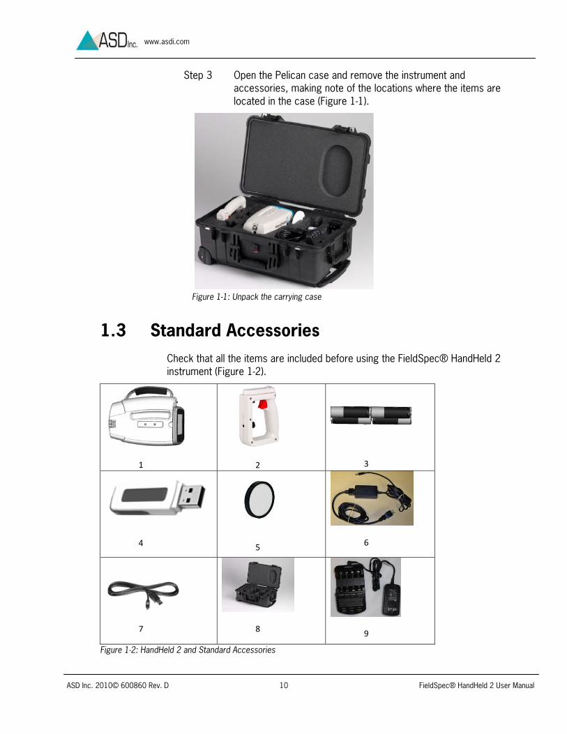
Step 3 Open the Pelican case and remove the instrument and accessories, making note of the locations where the items are located in the case (Figure 1-1).
Figure 1-1: Unpack the carrying case
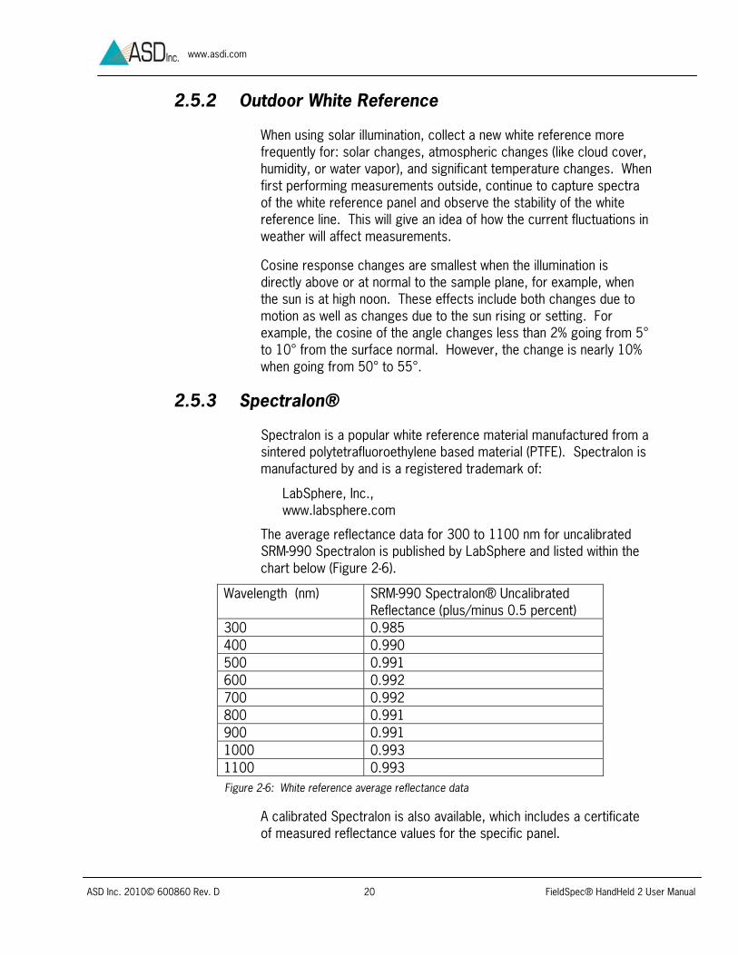
1.3 Standard Accessories Check that all the items are included before using the FieldSpec® HandHeld 2 instrument (Figure 1-2).
1
2
3
4
5
6
7
8
9
Figure 1-2: HandHeld 2 and Standard Accessories

ASD Inc. 2010© 600860 Rev. D 11 FieldSpec® HandHeld 2 User Manual
www.asdi.com
1. HandHeld 2 instrument 2. Handle 3. 4 rechargeable NiMH AA Batteries 4. 2 GB (Or better) USB Flash Drive which includes electronic copies of
the following documents and software: User Manual, RS3 Software, ViewSpec Pro Software, and HH2 Sync Software
5. 3.6" Round White Reference Panel 6. AC/DC Power Supply 7. USB cable 8. Case with foam inserts (Meets FAA airline carry-on requirements.) 9. Battery Charger
If an optional fiber optic cable was purchased, please see details on handling a fiber optic jumper cable in section 4.5 Care and Cleaning of Optional Fiber Optic Jumper Cables.
Note: Optional fiber optic jumper cable should never be stored for long periods of time with a bend diameter of less than five inches. The cable can become damaged with undetectable fractures that can cause decreased signal.
1.4 FieldSpec® HandHeld 2 Instrument Components
Figure 1-3: Front, Side and Bottom of HandHeld 2

ASD Inc. 2010© 600860 Rev. D 12 FieldSpec® HandHeld 2 User Manual
www.asdi.com
1 Optical input 8 Jack for optional remote trigger2 Laser pointer 9 5 Volt DC Power Input* 3 Threads for handle or optional tripod 10 Display Panel (Swivel Hinged)4 Trigger connection (for the Handle) 11 Battery compartment for 4 AA
Rechargeable Batteries 5 USB Mini-B for Tethered Mode only,
controlled by optional computer 12 Mounting threads for optional
spotting scope 6 USB A (female) 13 Thumb trigger button (red)7 USB A (female) 14 Hand strap
*Switches power from batteries to AC/DC when connected to AC/DC power supply
1.5 Holding and Mounting The HandHeld 2 instrument can be held using the hand strap, handle or an optional tripod (Figure 1-5).
Figure 1-5: Hand Strap
Figure 1-4: Back of HandHeld 2
10
12
13
14

ASD Inc. 2010© 600860 Rev. D 13 FieldSpec® HandHeld 2 User Manual
www.asdi.com
The handle can be attached in either of two orientations (Figure 1-6).
Figure 1-6: HandHeld 2 handle attachment orientations
The connector cover attaches to the handle and must be installed to complete the circuit which allows the trigger on the handle to be used to save spectra instead of the thumb trigger button. When the handle is in use, the cover also maintains the condition of the unused contacts.
The HandHeld 2 instrument can also be mounted on a tripod using the 1/4-20 threaded hole on the underside of the instrument. The tripods are optional accessories available from ASD, Inc.
1.6 Install the Batteries or Attach the Power Supply
Note: Before using the AC/DC Power Supply, batteries, or battery charger, read all following precautions.
To reduce risk of burns, fire, electric shock or injury:
The AC/DC power supply is intended for Indoor Use Only. Do not use outdoors.
A power supply should never be left unattended when plugged in. Always unplug the power supply from the main socket immediately after using.
Use only attachments recommended by the manufacturer.
Never operate the power supply if it has a damaged cord or plug, if it has been dropped or damaged or if it has fallen into water. In such
Ha
Connector

ASD Inc. 2010© 600860 Rev. D 14 FieldSpec® HandHeld 2 User Manual
www.asdi.com
cases return the power supply to an authorized dealer or service center for examination or repair.
Never drop or insert an object into any openings.
Do not operate where aerosol (spray) products are being used or where oxygen is being administered.
The FieldSpec® HandHeld 2 instrument uses non-rechargeable AA batteries or rechargeable AA batteries. However, do NOT use rechargeable Li Ion batteries.
The battery specifications are:
Type: AA Batteries (single use or rechargeable). Do NOT use Li Ion Batteries.
Rating: 1.2 Volts each
Performance: HandHeld 2 runtime with a fully charged battery depends on many variables including: battery age, instrument configuration, and environment.
o Approximately 2½ hours for rechargeable nickel-metal-hydride batteries
o Approximately 5 hours for non-rechargeable lithium batteries
Recycle batteries. Do not dispose of as general waste.
Step 1 Open the battery door by pushing down on the latch.
Step 2 Follow the polarity instructions stamped in the housing (Figure 1-7) and insert the four AA batteries. If using rechargeable batteries, fully charge them before using for the first time.
Figure 1-7: Battery Polarity

ASD Inc. 2010© 600860 Rev. D 15 FieldSpec® HandHeld 2 User Manual
www.asdi.com
Step 3 Close the battery door.
Note: Once replacement becomes necessary, be sure to turn off the HandHeld 2 instrument before removing the batteries.
An AC/DC Power Supply is included with the HandHeld 2 system (Figure 1-8). This power supply may be used instead of batteries to power the HandHeld 2 instrument from an AC outlet. Plug the AC/DC Power Supply into an AC outlet and connect the cable from the power supply into the socket on the instrument. Notice that the notches in the instrument power plug socket must receive the posts of the power plug in a specific orientation (Figure 1-9).
Note: Use only ASD approved power supplies and connectors to power the instrument.
Figure 1-8: AC/DC Power Supply Figure 1-9: Notched power plug socket and posts on power plug

ASD Inc. 2010© 600860 Rev. D 16 FieldSpec® HandHeld 2 User Manual
www.asdi.com
Chapter 2 Operation
There are two ways to control the FieldSpec® HandHeld 2 instrument and collect data:
Standalone Mode— This mode uses only the internal control and data collection capabilities of the HandHeld 2.
Tethered Mode— This mode combines the capabilities of the HandHeld 2 with the power of an optional external controller computer.
If using the HandHeld 2 instrument for the first time, start with the Standalone Mode. This mode is the fastest and easiest way to make measurements. In this first run, all settings will be defined by the default system preset.
2.1 Control and Display Panel
Figure 2-1: HandHeld 2 Display Screen
1 Power Indicator LED
2 ON/OFF Button
3 LCD Display
4 Laser Pointer ON/OFF
5‐8 Menu Buttons
9 Thumb Trigger Button (red)
1
2
3
4
5 6 7 8
9

ASD Inc. 2010© 600860 Rev. D 17 FieldSpec® HandHeld 2 User Manual
www.asdi.com
2.2 Power On Before powering on the HandHeld 2 instrument, ensure that the batteries are fully charged and installed or that the AC/DC Power Supply is connected to the instrument and plugged into a working outlet.
To power on the HandHeld 2 instrument, press the On/off button (Figure 2-1). The small LED above the on/off button will illuminate when powered on. After a few seconds, the ASD logo will appear and it will stay on for about 30 seconds while the system loads.
2.3 Spectrum Display After about 30 seconds the spectrum display mode should appear (2-2). When the HandHeld 2 is aimed at a lamp or brightly illuminated surface, the curve will move on the display screen. If the light is too bright for the present settings, the curve will go above the display scale and “SATURATION ALERT” will be displayed. Saturation alert is described in section 2.6 Saturation Alert.
If the menu button is hit by accident and icons appear, press the EXIT button to return to the spectrum display view (Figure 2-3).
Figure 2-2: Spectrum Display
Figure 2-3: Exit to return to spectrum display

ASD Inc. 2010© 600860 Rev. D 18 FieldSpec® HandHeld 2 User Manual
www.asdi.com
2.4 Choose Test Sample Illumination If the HandHeld 2 is being used for the first time, start with measurements outdoors, using the solar illumination. Do not attach any fore optics. Instead use the bare optical input of the HandHeld 2. This scenario is the fastest and easiest way to make measurements. If fore optics are used later on, be sure to set the Fore Optic menu to the correct fore optic before taking any measurements (Refer to section 2.15 Fore Optic Menu).
If the sky is cloudy, it is night time, or if working indoors, set up a suitable DC-powered tungsten quartz halogen lamp, such as ASD’s Pro Lamp system.
2.5 View White Reference Panel Choose a suitable white reference panel, such as the three inch round white reference panel which comes standard with the HandHeld 2 instrument or the five inch square panel (sold separately). Hold or mount the panel so that it is level and fully illuminated.
Aim the HandHeld 2 instrument so that optical input is viewing but not shading the white reference panel and is still close enough to ensure the field-of-view is filled by the panel (Figure 2-4). For a five inch square panel, keep the distance within nine inches. For a three inch round panel, keep the distance within four inches. Dark clothing helps minimize light reflected from the operator.
Note: The diameter of the spot size is approximately half of the height.
Figure 2-4: Aim the HandHeld 2 at the White Reference Panel
With the HandHeld 2 instrument viewing the white reference panel, a curve (called a raw DN spectrum) is displayed, signified by D on the Y axis (Figure 2-5). Raw DN is the raw output of the detector converted to digital numbers.
Field-of-view

ASD Inc. 2010© 600860 Rev. D 19 FieldSpec® HandHeld 2 User Manual
www.asdi.com
This display updates in real-time. As the HandHeld 2 instrument views different illumination levels or different surfaces, the curve on the display will change.
2.5.1 White Reference General Information
One way to collect the light incident on the sample is to use a white reference panel, which is also called a white reference standard. White means the panel diffusely reflects nearly 100% of the incident light throughout the spectral range. In other words, the reflectance values of the white reference panel are nearly 1 at every wavelength.
ASD application software can store the incident illumination from the white reference panel, which we call the white reference or WR. Then the software can calculate the actual reflectance of a sample using the measured light reflected from the sample.
For Best Results:
A white reference should be collected approximately every ten minutes—with this interval varied depending upon the rate of changes within illumination conditions. Also update the white reference whenever there are changes to fore optics or accessories. The white reference panel should be used when optimizing and taking a white reference measurement.
When using artificial illumination, the white reference panel should be at the same distance from the HandHeld 2’s optical input as the sample will be during measurements.
Note: If the illumination level changes significantly, the stored white reference might no longer be valid. If the reflectance spectrum of the white reference panel has deviated significantly from 1, a new white reference measurement may be needed. If it is significantly greater than 1, re-optimization is also recommended.
Figure 2-5: Raw DN Spectrum
ASD Inc. 2010© 600860 Rev. D 20 FieldSpec® HandHeld 2 User Manual
www.asdi.com
2.5.2 Outdoor White Reference
When using solar illumination, collect a new white reference more frequently for: solar changes, atmospheric changes (like cloud cover, humidity, or water vapor), and significant temperature changes. When first performing measurements outside, continue to capture spectra of the white reference panel and observe the stability of the white reference line. This will give an idea of how the current fluctuations in weather will affect measurements.
Cosine response changes are smallest when the illumination is directly above or at normal to the sample plane, for example, when the sun is at high noon. These effects include both changes due to motion as well as changes due to the sun rising or setting. For example, the cosine of the angle changes less than 2% going from 5° to 10° from the surface normal. However, the change is nearly 10% when going from 50° to 55°.
2.5.3 Spectralon®
Spectralon is a popular white reference material manufactured from a sintered polytetrafluoroethylene based material (PTFE). Spectralon is manufactured by and is a registered trademark of:
LabSphere, Inc., www.labsphere.com
The average reflectance data for 300 to 1100 nm for uncalibrated SRM-990 Spectralon is published by LabSphere and listed within the chart below (Figure 2-6).
Wavelength (nm) SRM-990 Spectralon® Uncalibrated Reflectance (plus/minus 0.5 percent)
300 0.985 400 0.990 500 0.991 600 0.992 700 0.992 800 0.991 900 0.991 1000 0.993 1100 0.993
A calibrated Spectralon is also available, which includes a certificate of measured reflectance values for the specific panel.
Figure 2-6: White reference average reflectance data

ASD Inc. 2010© 600860 Rev. D 21 FieldSpec® HandHeld 2 User Manual
www.asdi.com
The HandHeld 2 instrument’s Standalone Mode software and Tethered Mode RS3 software assumes that the white reference panel is 100% reflecting (reflectance values of 1 at each wavelength). However, the actual reflectance values are less than 1 (Figure 2-6). These small discrepancies are systematic uncertainties which can be accounted for during post-processing on ASD’s ViewSpec Pro software. Or if using Tethered Mode RS3 software, the measured reflectance values of a calibrated Spectralon panel can be used with the Absolute Reflectance setting.
Note: To clean Spectralon, see section 4.1 Care and Cleaning of Spectralon.
2.5.4 Transmittance White Reference
Transmittance = Light passing through sample/light incident on sample
Sometimes the term white reference—often referred to as a blank—is also used for transmittance measurements. The blank is calculated by measuring the incident light directly, or in the case of liquids, by measuring the light passing through an empty glass container.
In ASD application software, such as RS3, the scale can be changed to show transmittance. Unlike reflectance, transmittance is the collection of light through the sample instead of reflected from the sample. Please see the ASD Accessories manual and the ASD web page for optional accessories configured specifically for transmittance measurements.
2.6 Saturation Alert If the light is too bright for the present settings, the curve will go above the display scale and SATURATION ALERT will be displayed. If this warning appears, the model must be optimized as discussed in section 2.7 Optimization.
2.7 Optimization Optimization should be updated when illumination changes significantly or when the instrument software gives a saturation alert. If the relative reflectance of the reference panel is greater than one, optimization is necessary.
A well-optimized instrument will display between 20,000 and 35,000 raw digital numbers. Ideally, the peak of the raw digital numbers curve should be

ASD Inc. 2010© 600860 Rev. D 22 FieldSpec® HandHeld 2 User Manual
www.asdi.com
three quarters of full scale while the HandHeld 2 instrument is viewing the white reference panel. If the peak of the raw digital numbers curve is too high (saturated) or too low, press the OPT (optimization) button (Figure 2-7). This function will find the ideal integration time in order to maximize the signal-to-noise ratio without saturation.
Note: Refer to 2.12.3 Integration Time Menu to perform this task manually.
When prompted by the “Push trigger to optimize” message, point the HandHeld 2 instrument at the white reference panel—carefully following all directions listed in section 2.5 View White Reference Panel—and press the thumb trigger button (Figure 2-8).
Figure 2-8: Press thumb trigger to optimize
Keep steadily pointing the HandHeld 2 instrument at the panel until the process is completed, which is indicated by an updated raw DN spectrum.
2.8 Dark Current and White Reference In order to collect reflectance spectra, the HandHeld 2 instrument must first establish a baseline measurement by calculating both the dark current (DC) and white reference (WR) simultaneously.
Figure 2-7: OPT Button
ASD Inc. 2010© 600860 Rev. D 23 FieldSpec® HandHeld 2 User Manual
www.asdi.com
Step 1 Follow the same protocol as listed in 2.5 for viewing a white reference panel.
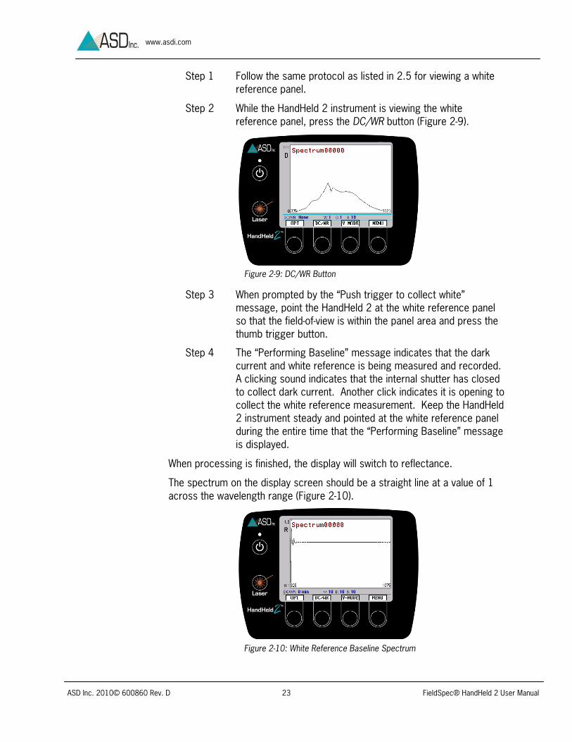
Step 2 While the HandHeld 2 instrument is viewing the white reference panel, press the DC/WR button (Figure 2-9).
Step 3 When prompted by the “Push trigger to collect white” message, point the HandHeld 2 at the white reference panel so that the field-of-view is within the panel area and press the thumb trigger button.
Step 4 The “Performing Baseline” message indicates that the dark current and white reference is being measured and recorded. A clicking sound indicates that the internal shutter has closed to collect dark current. Another click indicates it is opening to collect the white reference measurement. Keep the HandHeld 2 instrument steady and pointed at the white reference panel during the entire time that the “Performing Baseline” message is displayed.
When processing is finished, the display will switch to reflectance.
The spectrum on the display screen should be a straight line at a value of 1 across the wavelength range (Figure 2-10).
Figure 2-9: DC/WR Button
Figure 2-10: White Reference Baseline Spectrum

ASD Inc. 2010© 600860 Rev. D 24 FieldSpec® HandHeld 2 User Manual
www.asdi.com
There may be a little noise at the low end due to low energy from the sun or illumination source in this region, as well as a loss of energy absorbed in the atmosphere.
2.9 View a Sample’s Spectrum Similarly to the white reference setup, aim the HandHeld 2 to view a sample and ensure that it is close enough to fill the field-of-view with the sample. Avoid shadowing the viewed surface, as demonstrated in Figure 2-11.
Figure 2-11: Viewing sample
The screen will now display a reflectance spectrum (Figure 2-12).
Note: While aiming at the sample, the spectrum is displayed, but not stored. See 2.10 in order to store the spectrum.
2.10 Store a Spectrum Depress the red thumb button (to the right of the screen) to store a spectrum to the internal memory of the HandHeld 2 instrument. The HandHeld 2
Figure 2-12: Sample Spectrum
ASD Inc. 2010© 600860 Rev. D 25 FieldSpec® HandHeld 2 User Manual
www.asdi.com
instrument has an internal spectrum data storage capacity of 500 megabytes and each spectrum file is about 30 kilobytes, which allows for approximately 16,600 spectra to be stored.
Note: However, to maintain the best performance, it is recommended that 2,000 files at most are stored on the instrument at any one time. Storing more files will impact the speed of the processor.
2.11 Laser Pointer
Press the Laser button to turn on the laser pointer just below the instrument optical input (Figure 2-1).
The laser will come on for approximately five seconds and either: 1.) Go off at the end of this time span or 2.) The laser will turn off as soon as the thumb trigger button is pressed. The laser must be off during spectrum collection to prevent the intense laser light from becoming a source of noise in the spectrum.
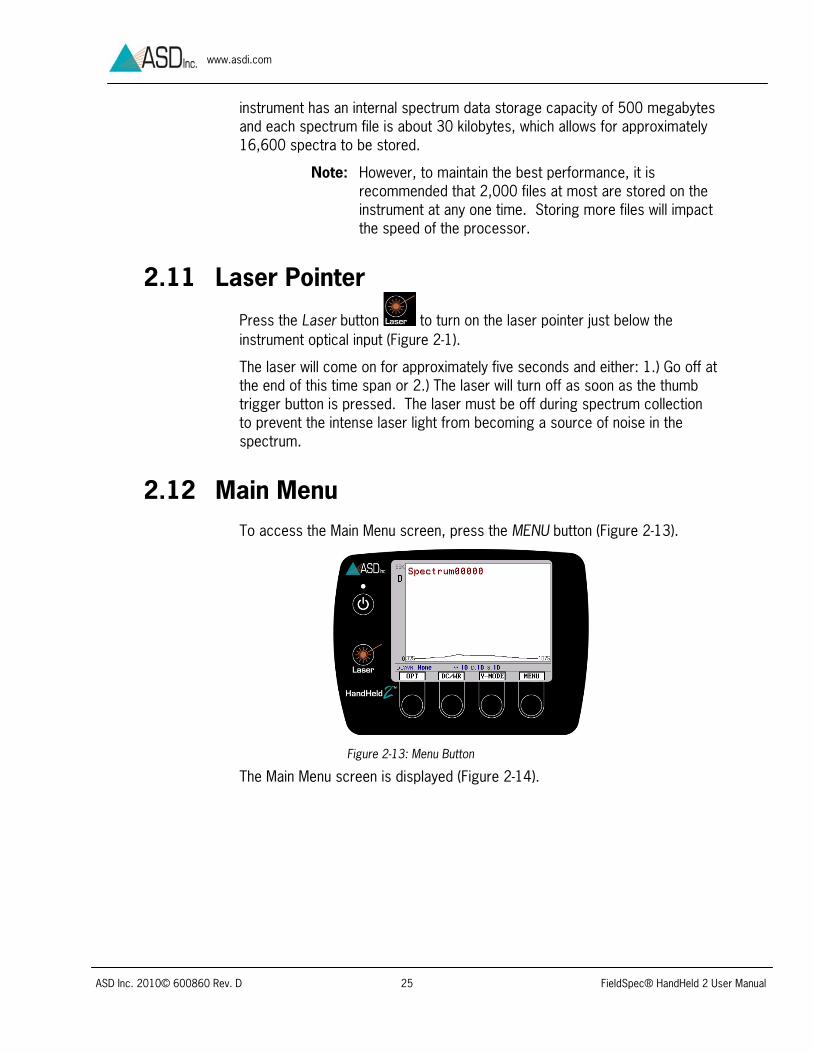
2.12 Main Menu To access the Main Menu screen, press the MENU button (Figure 2-13).
The Main Menu screen is displayed (Figure 2-14).
Figure 2-13: Menu Button

ASD Inc. 2010© 600860 Rev. D 26 FieldSpec® HandHeld 2 User Manual
www.asdi.com
The main menu contains five icons:
System Presets – Allows selection of a system preset group.
Fore Optics – Allows selection of a fore optic.
File Save – Enables access to the File Save menu.
Integration Time – Allows selection of system integration time.
Spectrum Counts – Allows user to select white reference, dark current and spectrum sample counts.
The selection of an icon is indicated by a black box around the icon. Use the left and right navigation keys to change icon selection. Navigate to System Presets.
2.12.1 System Presets
Step 1 Press the SEL (select) button to open the System Presets Menu (Figure 2-15).
Figure 2-14: Main Menu
Figure 2-15: Navigate to System Presets

ASD Inc. 2010© 600860 Rev. D 27 FieldSpec® HandHeld 2 User Manual
www.asdi.com
Step 2 Navigate to the Group labeled DefaultSet with the up and down arrow buttons, and press the SEL button (Figure 2-16). (Or cancel out of the screen by pressing the CANC button.)
Note: Other user defined settings will be discussed in Chapter 3 External Computer Access & Control (Tethered Mode).
2.12.2 Fore Optic Menu
The HandHeld 2 bare optical input has a 25 degree full conical angle field-of-view. Optional fore optics are available for limiting the field-of-view to smaller angles and for collecting full hemispherical irradiance. These optional fore optics screw onto the front of the bare optical input.
Note: Before making any measurements, it is essential to follow the directions below and select the fore optic presently in use on the HandHeld 2 instrument, or to select “Bare Fiber” for no attached fore optic.
Step 1 Navigate to the fore optic icon by pressing the arrow buttons, and press SEL to select icon (Figure 2-17).
Figure 2-16: Select Group
Figure 2-17: Navigate to Fore Optic Menu

ASD Inc. 2010© 600860 Rev. D 28 FieldSpec® HandHeld 2 User Manual
www.asdi.com
Step 2 If using the HandHeld 2 for the first time, navigate to the “Bare Fiber” configuration (which means that no fore optic is attached) and press SEL (Figure 2-18).
Figure 2-18: Choose Fore optic Type
2.12.3 Integration Time Menu
Integration time is the set time interval for detector build-up of electric signal converted from the incoming light. After each build-up, the electric signal is read and cleared-out for the next build-up.
The optimization function automatically selects the integration time. However, the integration time can be set manually. In some instances, this may improve the signal-to-noise ratio.
Step 1 Navigate to the Integration Time menu icon and press the SEL button (Figure 2-19).
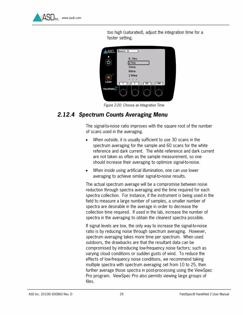
Step 2 Press the arrow buttons to move the selection box to the desired integration time (Figure 2-20).
Note: The peak of the raw DN curve should be three quarters of full scale while the HandHeld 2 instrument is viewing the white reference panel. If the peak DN is too low, adjust the integration time for a slower setting. If the peak DN is
Figure 2-19: Integration Time menu icon
ASD Inc. 2010© 600860 Rev. D 29 FieldSpec® HandHeld 2 User Manual
www.asdi.com
too high (saturated), adjust the integration time for a faster setting.
2.12.4 Spectrum Counts Averaging Menu
The signal-to-noise ratio improves with the square root of the number of scans used in the averaging.
When outside, it is usually sufficient to use 30 scans in the spectrum averaging for the sample and 60 scans for the white reference and dark current. The white reference and dark current are not taken as often as the sample measurement, so one should increase their averaging to optimize signal-to-noise.
When inside using artificial illumination, one can use lower averaging to achieve similar signal-to-noise results.
The actual spectrum average will be a compromise between noise reduction through spectra averaging and the time required for each spectra collection. For instance, if the instrument is being used in the field to measure a large number of samples, a smaller number of spectra are desirable in the average in order to decrease the collection time required. If used in the lab, increase the number of spectra in the averaging to obtain the cleanest spectra possible.
If signal levels are low, the only way to increase the signal-to-noise ratio is by reducing noise through spectrum averaging. However, spectrum averaging takes more time per spectrum. When used outdoors, the drawbacks are that the resultant data can be compromised by introducing low-frequency noise factors; such as varying cloud conditions or sudden gusts of wind. To reduce the effects of low-frequency noise conditions, we recommend taking multiple spectra with spectrum averaging set from 10 to 25, then further average those spectra in post-processing using the ViewSpec Pro program. ViewSpec Pro also permits viewing large groups of files.
Figure 2-20: Choose an Integration Time

ASD Inc. 2010© 600860 Rev. D 30 FieldSpec® HandHeld 2 User Manual
www.asdi.com
Step 1 Navigate to the Spectrum Counts menu icon and press the SEL button (Figure 2-21).
Step 2 Navigate to the desirable icon and press the SEL button (Figure 2-22). In the quotients below, w for white reference averaging count, d for dark current averaging count, or s for sample averaging count s is sample, d is dark current, and w is white reference. The quotients are menu labels which demonstrate the calculation of each of the spectrum averages. For example, in order to compute the white reference averaging count, the equation is (sample minus dark current) divided by (white reference minus dark current). To simplify this, the letter representing the proper spectrum averaging count is highlighted in red, making it is clear that the first equation refers to the white reference averaging count, etc.
Figure 2-22: Navigate to White, Dark, or Sample
Note: The default settings are from the System Presets (Refer to section 2.12.1 System Presets). However, these presets can be overridden from this menu.
Step 3 Navigate to the desired number position and press the arrow buttons to change the numbers. Ten spectra averaging is convenient in terms of measurement speed, however a higher
Figure 2-21: Navigate to Spectrum Counts menu icon

ASD Inc. 2010© 600860 Rev. D 31 FieldSpec® HandHeld 2 User Manual
www.asdi.com
number might be called for depending upon illumination and target reflectance (Figure 2-23).
Step 4 When finished, press the SEL button to return to the Spectrum Counts submenu.
Step 5 Press the EXIT button to return to the main menu.
2.13 File Save Menu Step 1 Navigate to the File Save Menu icon and press the SEL button
(Figure 2-24).
The File Save Menu contains five submenu icons (Figure 2-25):
Base Name – Allows selection of a base name for sequential spectrum saves. The number suffix will automatically increment with each spectrum save so each spectral file has a unique file name. For example, using the base name, “Spectrum”: Spectrum00000, Spectrum00001, Spectrum00002, etc.
Figure 2-24: Navigate to File Save Icon
Figure 2-23: Navigate to number position
ASD Inc. 2010© 600860 Rev. D 32 FieldSpec® HandHeld 2 User Manual
www.asdi.com
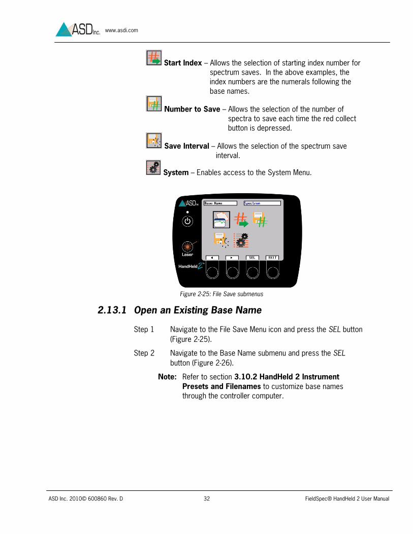
Start Index – Allows the selection of starting index number for spectrum saves. In the above examples, the index numbers are the numerals following the base names.
Number to Save – Allows the selection of the number of spectra to save each time the red collect button is depressed.
Save Interval – Allows the selection of the spectrum save interval.
System – Enables access to the System Menu.
2.13.1 Open an Existing Base Name
Step 1 Navigate to the File Save Menu icon and press the SEL button (Figure 2-25).
Step 2 Navigate to the Base Name submenu and press the SEL button (Figure 2-26).
Note: Refer to section 3.10.2 HandHeld 2 Instrument Presets and Filenames to customize base names through the controller computer.
Figure 2-25: File Save submenus

ASD Inc. 2010© 600860 Rev. D 33 FieldSpec® HandHeld 2 User Manual
www.asdi.com
Step 3 To open an existing base name, press the SEL button.
Step 4 If this is the instrument’s first time in use, press SEL to select a default name, for example, “Spectrum” (Figure 2-27).
2.13.2 Create a New Base Name
This feature allows the selection of a base name for sequential spectrum saves. The number suffix will automatically increment with each spectrum save so each spectral file has a unique file name. For example, using the base name, “Spectrum”: Spectrum00000 Spectrum00001, Spectrum00002, etc.
Step 1 Navigate to the File Save Menu icon and press the SEL button. (Figure 2-25).
Step 2 To create a new base name, select Base Name from the File Save submenu.
Step 3 Navigate to “<NEW>” and press SEL button (Figure 2-28).
Figure 2-26: Navigate to the Base Name Icon
Figure 2-27: Navigate to “Spectrum” Filename

ASD Inc. 2010© 600860 Rev. D 34 FieldSpec® HandHeld 2 User Manual
www.asdi.com
Step 4 A filename may be up to eight characters long and it may not contain spaces. Press the up or down arrow buttons to change the characters (Figure 2-29).
Step 5 Press the right arrow button to move to the next character position and repeat steps 4 and 5 until complete, at which time press SEL button.
Note: If it is necessary to return to the first character position, press the right arrow button repeatedly.
Step 8 Press the SEL button to set the new name as the filename for the spectral files (Figure 2-30). This step will also return the screen to the File Save submenu.
Figure 2-28: Navigate to <NEW>
Figure 2-29: Set first character of filename

ASD Inc. 2010© 600860 Rev. D 35 FieldSpec® HandHeld 2 User Manual
www.asdi.com
2.13.3 Starting ID
This feature allows the selection of a starting index number for spectrum saves.
Step 1 Navigate to the File Save Menu icon and press the SEL button (Figure 2-25).
Step 2 Navigate to the Starting ID icon and press the SEL button (Figure 2-31).
Step 3 Press the arrow buttons to move to the desired number position (Figure 2-32).
Figure 2-32: Start Index Number Adjustment
Figure 2-30: Select newly created name
Figure 2-31: Navigate to Starting ID

ASD Inc. 2010© 600860 Rev. D 36 FieldSpec® HandHeld 2 User Manual
www.asdi.com
Step 4 Press the up or down arrow buttons to set the numbers.
Step 5 When finished, press the SEL button to go back to the File Save submenus menu.
2.13.4 Number to Save
Through this feature, one can select the number of spectra to be saved each time the red collect button is depressed.
Step 1 Navigate to the File Save Menu icon and press the SEL button (Figure 2-25).
Step 2 Navigate to the Number to Save icon and press the SEL Button (Figure 2-33).
Step 3 Press the left pointing arrow to move to the desired number position and press the up and down arrows to change the number (Figure 2-34).
Note: For most situations, this should be set to one. If collecting measurements automatically, adjust both this and the save interval—see section 2.13.5 Save Interval. If manually calculating the spectrum average, this can also be set to a value greater than one.
Figure 2-33: Navigate to Number to Save
Figure 2-34: Adjust Number to Save

ASD Inc. 2010© 600860 Rev. D 37 FieldSpec® HandHeld 2 User Manual
www.asdi.com
Step 4 When finished, press the SEL button, which will bring up the File Save submenu.
2.13.5 Save Interval
This feature allows the selection of the interval between spectra saved.
Step 1 Navigate to the File Save Menu icon and press the SEL button (Figure 2-25).
Step 2 Navigate to the Save Interval icon and press the SEL button (Figure 2-35).
Step 3 Although this should initially be set at 0, the number can be changed by pressing the left pointing arrow to move to the desired number position and using the up and down arrow buttons to set the numbers. If it is necessary to return to the first character position, press the right arrow button repeatedly (Figure 2-36).
Step 4 When finished, press the SEL button to go back to the File Save submenus.
Figure 2-35: Save Interval
Figure 2-36: Adjust Save Interval Numbers

ASD Inc. 2010© 600860 Rev. D 38 FieldSpec® HandHeld 2 User Manual
www.asdi.com
2.13.6 System Menu
Navigate to the System Menu icon and press the SEL (Figure 2-37).
The System Menu contains three submenu icons:
Set Clock – Allows the user to set the internal clock.
Software Version – Displays the current software version.
Update Software – Updates the HandHeld 2 software upon command.
Set Clock
Step 1 Navigate to the System Menu icon and press the SEL (Figure 2-37).
Step 2 Navigate to the Set Clock icon and press the SEL button (Figure 2-38).
Step 3 Press the SET button to set the time (Figure 2-39).
Figure 2-37: System Menu
Figure 2-38: Set Clock

ASD Inc. 2010© 600860 Rev. D 39 FieldSpec® HandHeld 2 User Manual
www.asdi.com
Step 4 Press the up and down arrow buttons to move the selection box to the current month and press the SEL button. Repeat for day, year, hour, and minute and press SEL when complete.
Software Version
Step 1 Navigate to the Software Version icon and press the SEL button to view the software version (Figure 2-40).
Step 2 Press OK to exit the screen.
Update Software
Step 1 Download the software update from the ASD Support site and save it at the root directory level onto a (four GB or less) flash drive.
Note: If the update is saved within a folder, it will be inaccessible to the HandHeld 2.
Step 2 Prior to the plugging the flash drive into the HandHeld 2, unplug other USB devices—including the GPS unit. The HandHeld 2 should be plugged into a power outlet and not on battery power during this procedure.
Figure 2-39: Set System Time
Figure 2-40: Inquire Software Version

ASD Inc. 2010© 600860 Rev. D 40 FieldSpec® HandHeld 2 User Manual
www.asdi.com
Step 3 Plug the flash drive into the HandHeld 2 USB port.
Step 4 Navigate to the Update Software icon and press the SEL button (Figure 2-41).
Step 4 When prompted, press the OK button for the update to occur. The screen will periodically indicate progress during the update procedure, which should take less than 10 minutes. After the update is complete, you will need to turn the instrument off and back on again to use the updated software.
Figure 2-41: Update Software icon
ASD Inc. 2010© 600860 Rev. D 41 FieldSpec® HandHeld 2 User Manual
www.asdi.com
Chapter 3 External Computer Access & Control (Tethered Mode)
A computer is used to import and process the data files stored on the FieldSpec® HandHeld 2 instrument, to create system presets, and to export instrument control files. The HandHeld 2 can be operated with an external computer to take advantage of the large screen, keyboard and data storage directly to the computer hard drive (optional notebook computers are available from ASD at additional cost). When connecting the HandHeld 2 to the computer with the included USB cable, the HandHeld 2 can be operated in Tethered Mode.
Note: Refer to section 5.2 Optional Computer Specifications.
3.1 Connect Computer to the FieldSpec® HandHeld 2 Instrument
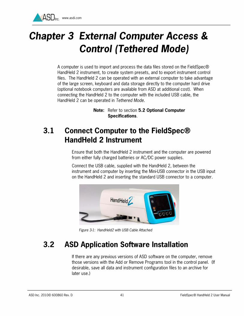
Ensure that both the HandHeld 2 instrument and the computer are powered from either fully charged batteries or AC/DC power supplies.
Connect the USB cable, supplied with the HandHeld 2, between the instrument and computer by inserting the Mini-USB connector in the USB input on the HandHeld 2 and inserting the standard USB connector to a computer.
Figure 3-1: HandHeld2 with USB Cable Attached
3.2 ASD Application Software Installation If there are any previous versions of ASD software on the computer, remove those versions with the Add or Remove Programs tool in the control panel. (If desirable, save all data and instrument configuration files to an archive for later use.)
ASD Inc. 2010© 600860 Rev. D 42 FieldSpec® HandHeld 2 User Manual
www.asdi.com
3.2.1 Windows 7 Setup
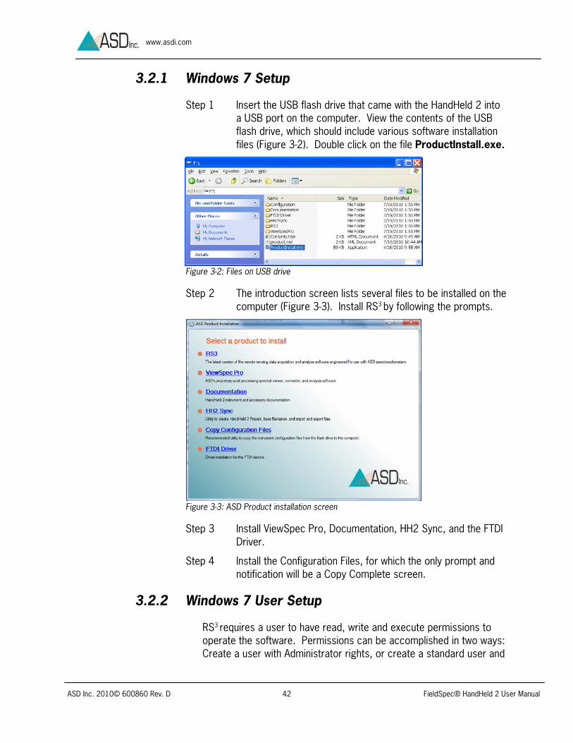
Step 1 Insert the USB flash drive that came with the HandHeld 2 into a USB port on the computer. View the contents of the USB flash drive, which should include various software installation files (Figure 3-2). Double click on the file ProductInstall.exe.
Figure 3-2: Files on USB drive
Step 2 The introduction screen lists several files to be installed on the computer (Figure 3-3). Install RS3 by following the prompts.
Figure 3-3: ASD Product installation screen
Step 3 Install ViewSpec Pro, Documentation, HH2 Sync, and the FTDI Driver.
Step 4 Install the Configuration Files, for which the only prompt and notification will be a Copy Complete screen.
3.2.2 Windows 7 User Setup
RS3 requires a user to have read, write and execute permissions to operate the software. Permissions can be accomplished in two ways: Create a user with Administrator rights, or create a standard user and

ASD Inc. 2010© 600860 Rev. D 43 FieldSpec® HandHeld 2 User Manual
www.asdi.com
provide read, write and execute permissions to the c:\Program Files\ASD folder and subfolders.
The following are steps on how to create a standard user and provide read, write and execute permissions.
Note: These steps require Administrator rights to perform.
Step 1 Turn off the User Account Control (UAC). Start ButtonControl PanelsUser Accounts. Select Turn User Account Control on or off. Uncheck User Account Control (UAC) to help protect
the computer. Select OK.
Step 2 Create a standard user. Start Button Control Panels Administrative
ToolsComputer Management Expand Local Users and Groups. Right click “Users.” Select “New User...” Create a new user. Click Close.
Step 3 Give Users group Full Control permission for the c:\Program Files\ASD folder and subfolders.
Right-click Start Button. Select “Explore.” Right-click c:\Program Files\ASD folder. Select
“Properties.” Select Security Tab. Select Edit button Select “Users Group.” Check Full control, Modify, Read and execute, List
folder contents, Read, Write. Click OK to close Permissions for ASD. Click OK to close ASD properties.
When all of the installations are finished, the following shortcuts will be on the desktop:
RS3 for controlling the HandHeld 2 instrument from an external controller computer.
RS3 with high contrast black and white screen for outdoor use.
HH2 Sync for importing data files from the HandHeld 2 instrument, managing the system presets and base file names, and exporting calibration files to the HandHeld 2 instrument.
ViewSpec™ Pro for post-processing spectra files saved using the HandHeld 2 instrument.

ASD Inc. 2010© 600860 Rev. D 44 FieldSpec® HandHeld 2 User Manual
www.asdi.com
3.3 ASD Software/Hardware Combinations The mode, communications, control and data collection capabilities of the different ASD applications software allow a variety of software and hardware combinations. The following table outlines the various software and their impact on communication modes, control functions and data management (Figure 3-4).
Note: For more in depth information on RS3 and ViewSpec Pro, see their individual user manuals.
Software Mode/Communication Control and data HandHeld 2 Standalone/all-internal
Control commands are sent from the HandHeld 2 instrument. Data is stored on internal HandHeld 2 storage. Spectrum and control screens show on built-in display.
RS3 Tethered/both directions
Control commands are sent from computer to HandHeld 2. Data sent from the HandHeld 2 to computer for display and storage (Data is not stored on HandHeld 2). Control buttons are in RS3 software, as well as the thumb trigger button on the HandHeld 2.
ViewSpec Pro Tethered/one direction, then computer only
Data must already be imported to the computer using HH2 Sync or saved using RS3. ViewSpec Pro imports ASD files from a folder on the computer, converts files to other formats and exports them to a folder on the computer.
HH2 Sync Import Spectrum Data Files from Instrument
Tethered/one direction Only imports spectral data files from the HandHeld 2 instrument to computer hard drive.
HH2 Sync Manage Instrument Presets and Base Filenames
Tethered/one direction
Exports presets from the computer to the HandHeld 2 instrument and links asdcfg.ini files from RS3 folder on computer.
HH2 Sync Export Calibration Files To Instrument
Tethered/one direction Only exports radiometric calibration files from computer to the HandHeld instrument.
HH2 Sync Copy Configuration Files
Computer, then Tethered/one direction For copying updated configuration file asdcfg.ini from a USB flash drive to the RS3 folder on computer. Then, export asdcfg.ini to HandHeld 2 instrument using HH2 Sync.
Figure 3-4: Application Software/Hardware Matrix

ASD Inc. 2010© 600860 Rev. D 45 FieldSpec® HandHeld 2 User Manual
www.asdi.com
3.4 Operate RS3 Software RS3 Software allows for the HandHeld 2 to process data while in Tethered Mode. For more in depth information on, see RS3 User Manual located in the ASD Programs Documentation folder.
Step 1 Turn on the computer, and connect the computer to the HandHeld 2 with the USB cable.
Note: While the computer may be turned on before or after connecting the USB cable, these steps must be followed prior to turning on the HandHeld 2. Reversing these steps will result in Standalone Mode, rather than Tethered Mode.
Step 2 Turn on the HandHeld 2. The Tethered Mode message will appear on the display (Figure 3-5).
Step 3a Start the RS3 application by clicking on either of the shortcuts for RS3 or RS3 High Contrast on the computer desktop (Figure 3-6).
Figure 3-6: RS3 shortcuts
Step 3b Or, start the RS3 application from the Start menu: Select All ProgramsASD ProgramsRS3 (Figure 3-7).
Figure 3-7: RS3 from Start menu
Tethered Mode
Figure 3-5: Instrument Tethered Mode display

ASD Inc. 2010© 600860 Rev. D 46 FieldSpec® HandHeld 2 User Manual
www.asdi.com
Step 3c Or, start the RS3 application by navigating through the hard disk and its default location, in order to launch the executable file: C:\Program Files\ASD\RS3\RS3.exe
If the system is configured properly, the RS3 spectrum display will appear within 30 seconds (Figure 3-8).
Figure 3-8: RS3 spectrum display
If any communication issues occur, an error message will appear at the bottom-right corner of the spectrum display (Figure 3-9).
Figure 3-9: RS3 connection error
Wait approximately ten seconds while the RS3 software makes repeated attempts to find a good connection (Figure 3-10).
Figure 3-10: RS3 searching for connection
Step 3 If a good connection cannot be found after a minute, first disconnect and re-connect the USB cable. If this does not result in a good connection, next exit out of RS3 by clicking on the X button in the upper-right hand corner, or if necessary enter Ctrl-Alt-Del to quit the program through the “Task Manager.”
Once a good connection is made, the error message will change to a Connecting message (Figure 3-11).

ASD Inc. 2010© 600860 Rev. D 47 FieldSpec® HandHeld 2 User Manual
www.asdi.com
Figure 3-11: Connecting message
The main RS3 application window contains a graph region in the middle, a menu and toolbar at the top, GPS data at the bottom and data collection and status boxes on the left. Use the scroll bar to see all of the different data collection and status boxes.
Move the mouse cursor over the status dot at the bottom-right corner to see the connection status message (Figure 3-12).
Figure 3-12: Connection status
3.5 RS3 Pull-Down Menus RS3 has a small number of pull-down menus, which can all be accessed with the mouse or the keyboard (Figure 3-13):
Figure 3-13: RS3 pull-down menus
Display (Section 3.9)
Control (Section 3.6)
GPS (Section 3.12)
Help
When using the keyboard, press the Alt key and the key corresponding to the underlined letter in the menu name, such as Alt+D for Display.
Once the pull-down menu is open, further operations can be launched by pressing the key corresponding to the underlined letter in the desired pull-down menu item.
In addition, many RS3 operations are available directly through function keys (e.g., F1 through F12), other hot-key combinations, and icons within the application’s toolbar. The items listed in a given pull-down menus typically show their designated hot-key to the right.
ASD Inc. 2010© 600860 Rev. D 48 FieldSpec® HandHeld 2 User Manual
www.asdi.com
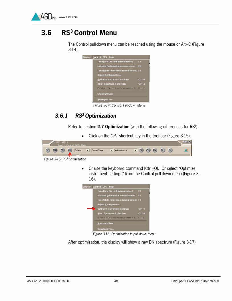
3.6 RS3 Control Menu The Control pull-down menu can be reached using the mouse or Alt+C (Figure 3-14).
Figure 3-14: Control Pull-down Menu
3.6.1 RS3 Optimization
Refer to section 2.7 Optimization (with the following differences for RS3):
Click on the OPT shortcut key in the tool bar (Figure 3-15).
Or use the keyboard command [Ctrl+O]. Or select “Optimize
instrument settings” from the Control pull-down menu (Figure 3-16).
After optimization, the display will show a raw DN spectrum (Figure 3-17).
Figure 3-15: RS3 optimization
Figure 3-16: Optimization in pull-down menu

ASD Inc. 2010© 600860 Rev. D 49 FieldSpec® HandHeld 2 User Manual
www.asdi.com
Figure 3-17: RS3 Raw DN optimized
3.6.2 RS3 White Reference
Refer to section 2.8 Dark Current and White Reference (with the following differences for RS3):
To take a white reference, click on the WR shortcut (Figure 3-18).
Or use the keyboard command [Alt+C, W], or F4 hotkey. Or select “Take White Reference measurement” from the Control pull-down menu (Figure 3-19).
After the white reference routine is complete, the display will show a reflectance spectrum of 1 across the entire wavelength range (Figure 3-20).
Figure 3-18: RS3 White reference
Figure 3-19: Pull down menu white reference

ASD Inc. 2010© 600860 Rev. D 50 FieldSpec® HandHeld 2 User Manual
www.asdi.com
Figure 3-20: RS3 white reference reflectance spectrum
3.6.3 RS3 Dark Current
For a separate dark current update (without updating the white reference), click on the DC shortcut key in the tool bar (Figure 3-21).
Or use the keyboard command [Alt+C, D], the F3 hotkey, or select “Take Dark Current measurement” from the Control pull-down menu (Figure 3-22).
3.6.4 RS3 Radiometric Measurement Command
This control activates the radiometric calibration for the fore optic configuration specified in the toolbar.
Figure 3-21: RS3 dark current
Figure 3-22: RS3 dark current pull-down menu

ASD Inc. 2010© 600860 Rev. D 51 FieldSpec® HandHeld 2 User Manual
www.asdi.com
Under the Control pull-down menu, select “Initialize Radiometric measurement” (Figure 3-23).
Or use Rad shortcut key in the toolbar, the keyboard command [Alt+C, R], or the F9 hotkey.
3.6.5 RS3 Adjust Configuration Settings
Step 1 Under the Control pull-down menu, select “Adjust Configuration...” (Figure 3-24) or use keyboard command [Alt+C, C].
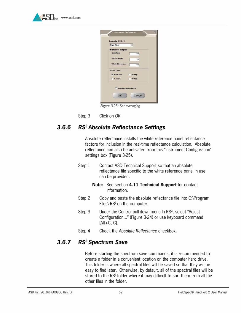
Step 2 In the “Instrument Configuration” settings box, set the number of samples to average for the sample spectrum, dark current and white reference (Figure 3-25).
Figure 3-23: Select Initialize Radiometric Measurement
Figure 3-24: Select Adjust Configuration
ASD Inc. 2010© 600860 Rev. D 52 FieldSpec® HandHeld 2 User Manual
www.asdi.com
Figure 3-25: Set averaging
Step 3 Click on OK.
3.6.6 RS3 Absolute Reflectance Settings
Absolute reflectance installs the white reference panel reflectance factors for inclusion in the real-time reflectance calculation. Absolute reflectance can also be activated from this “Instrument Configuration” settings box (Figure 3-25).
Step 1 Contact ASD Technical Support so that an absolute reflectance file specific to the white reference panel in use can be provided.
Note: See section 4.11 Technical Support for contact information.
Step 2 Copy and paste the absolute reflectance file into C:\Program Files\ RS3 on the computer.
Step 3 Under the Control pull-down menu In RS3, select “Adjust Configuration...” (Figure 3-24) or use keyboard command [Alt+C, C].
Step 4 Check the Absolute Reflectance checkbox.
3.6.7 RS3 Spectrum Save
Before starting the spectrum save commands, it is recommended to create a folder in a convenient location on the computer hard drive. This folder is where all spectral files will be saved so that they will be easy to find later. Otherwise, by default, all of the spectral files will be stored to the RS3 folder where it may difficult to sort them from all the other files in the folder.

ASD Inc. 2010© 600860 Rev. D 53 FieldSpec® HandHeld 2 User Manual
www.asdi.com
For additional information, refer to section 2.10 Store a Spectrum (with the following differences for RS3):
Step 1 Under the Control pull-down menu, select “Spectrum Save” (Figure 3-26) or use keyboard command [Alt+S].
Step 2 Enter the information in the Spectrum Save settings box (Figure 3-27).
Figure 3-27: Spectrum Save settings
Step 3 Use the browse button to find the folder previously set up for the spectral files and create this path.
Step 4 Saving spectra can now be performed by clicking on the Begin Save button. It can also be done by using save commands from spectral display window.
Note: To store a spectrum to the computer hard drive, press the spacebar key on the computer or the thumb trigger button on the HandHeld 2 instrument.
3.7 RS3 Fore Optics If a fore optic is attached to the optical input of the HandHeld 2 instrument, ensure that the correct fore optic is selected in the toolbar fore optic pull-down menu before taking any measurements (Figure 3-28).
Browse button
Figure 3-26: Select Spectrum Save

ASD Inc. 2010© 600860 Rev. D 54 FieldSpec® HandHeld 2 User Manual
www.asdi.com
Use the following procedures from the previous sections on the Standalone Mode:
Refer to section 2.4 Choose A Test Sample
Refer to section 2.5 View White Reference Panel
3.8 RS3 Saturation Alert Refer to section 2.6 Saturation Alert (with the following differences for RS3): When saturation occurs an audible beep will sound and the Spectrum Avg progress control will display “Saturation” (Figure 3-29).
Figure 3-29: RS3 saturation in DN mode
3.9 RS3 Display Pull-Down Menu The Display pull-down menu can be reached using the mouse or Alt+D (Figure 3-30).
Figure 3-30: Display pull-down menu
Figure 3-28: RS3 fore optic choice in toolbar

ASD Inc. 2010© 600860 Rev. D 55 FieldSpec® HandHeld 2 User Manual
www.asdi.com
This menu includes:
Axes Cursor Grid Line Properties View Files Freeze Quit
3.9.1 RS3 Axis Settings
Select “Axes...” (Figure 3-31).
Or use keyboard command [Alt+D, A]. Both the minimum and maximum levels can be set within this screen (Figure 3-32). If the viewable range is changed, this dialog box can also be used to restore the default ranges. While the X-axis remains in wavelengths (nm), the Y-axis type can be changed to:
Raw DN (Digital Number coming from the instrument) Transmission Reflectance Radiance Irradiance Absorption
Figure 3-31: Axis menu

ASD Inc. 2010© 600860 Rev. D 56 FieldSpec® HandHeld 2 User Manual
www.asdi.com
Figure 3-32: The Axes... item [Alt+D, A] to configure the display axes
Note: In order to change the Y-axis type from this dialog box, a white reference must first be initiated for the desired type. With the exception of the axis type, these same XY range parameters can be changed using the options from “Cursor...” [Alt+D, C] or the toolbar buttons, such as Pan, Zm, or XY.
3.9.2 RS3 Cursor Settings
Select “Cursor...” (Figure 3-33)
Or use keyboard command [Alt+D, C]. The Cursor Mode settings box shows check boxes to assist viewing an appropriate range of the spectrum (Figure 3-34).
Figure 3-33: Cursor menu

ASD Inc. 2010© 600860 Rev. D 57 FieldSpec® HandHeld 2 User Manual
www.asdi.com
Figure 3-34: Cursor mode
The operations available from this settings box are also available from the toolbar (Figure 3-35).
Pan button (or Pan Mode setting) moves the zoom viewing rectangle through the use of the horizontal and vertical scroll bars, or the left/right up/down arrow keys of the keyboard. Pressing Ctrl+arrow keys moves the viewing rectangle in larger steps.
Zm button (or Zoom Mode setting) allows the user to click & drag a rectangle with the cursor in the graphing area, thereby zooming the viewing area and the XY-axis scaling to that range. The left/right up/down arrow keys of the keyboard can also be used to zoom in the image. The Ctrl+arrow keys zoom the viewing rectangle in larger steps. The right-mouse button has an option to Undo Zoom.
XY button (or Coordinate Mode setting) allows the user to move the cursor to a specific point in the spectrum and have its XY coordinates displayed in the lower left-hand corner of the main RS3
display (Figure 3-36). The point can be specified with the mouse or with the left/right up/down arrow keys of the keyboard.
Figure 3-36: Coordinates display box
Figure 3-35: Cursor toolbar buttons
ASD Inc. 2010© 600860 Rev. D 58 FieldSpec® HandHeld 2 User Manual
www.asdi.com
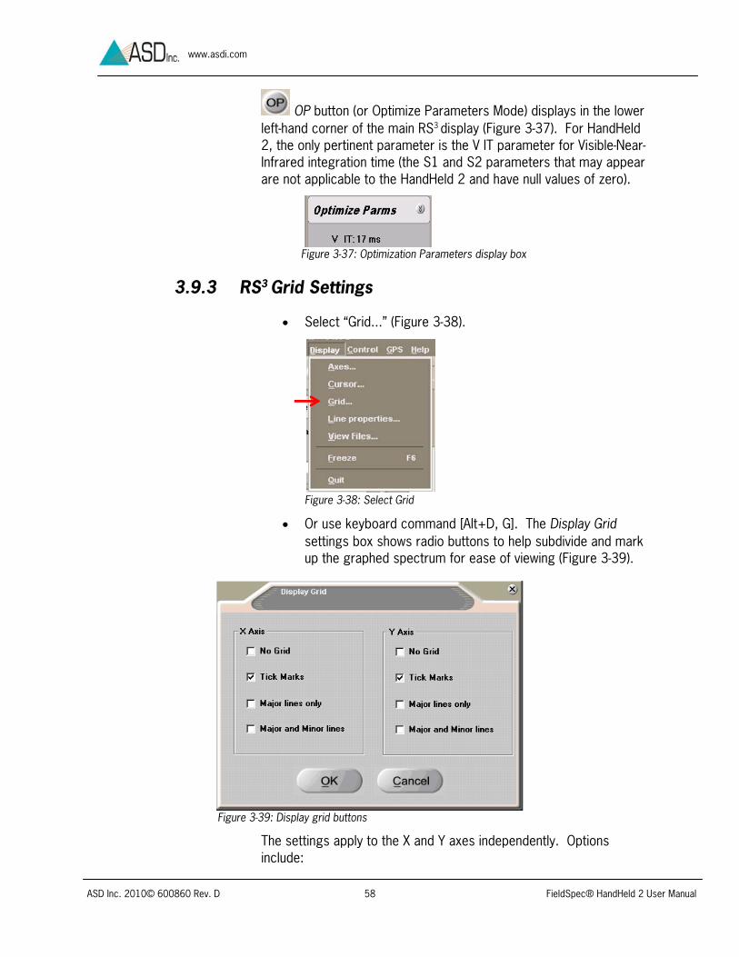
OP button (or Optimize Parameters Mode) displays in the lower left-hand corner of the main RS3 display (Figure 3-37). For HandHeld 2, the only pertinent parameter is the V IT parameter for Visible-Near-Infrared integration time (the S1 and S2 parameters that may appear are not applicable to the HandHeld 2 and have null values of zero).
Figure 3-37: Optimization Parameters display box
3.9.3 RS3 Grid Settings
Select “Grid...” (Figure 3-38).
Or use keyboard command [Alt+D, G]. The Display Grid settings box shows radio buttons to help subdivide and mark up the graphed spectrum for ease of viewing (Figure 3-39).
Figure 3-39: Display grid buttons
The settings apply to the X and Y axes independently. Options include:
Figure 3-38: Select Grid
ASD Inc. 2010© 600860 Rev. D 59 FieldSpec® HandHeld 2 User Manual
www.asdi.com
No Grid: Turns off the grid in order to override the previous settings.
Tick Marks: Turns on tick marks along the respective X and/or Y axis to help distinguish the range.
Major Lines Only: Turns on graph lines for major division that extend across the graph from the selected axis. The interval used for the major line depends on the zoom scaling.
Major Lines and Minor Lines: Turns on graph lines for all divisions that extend across the graph from the selected axis. The interval for the grid markings depends on the zoom scaling.
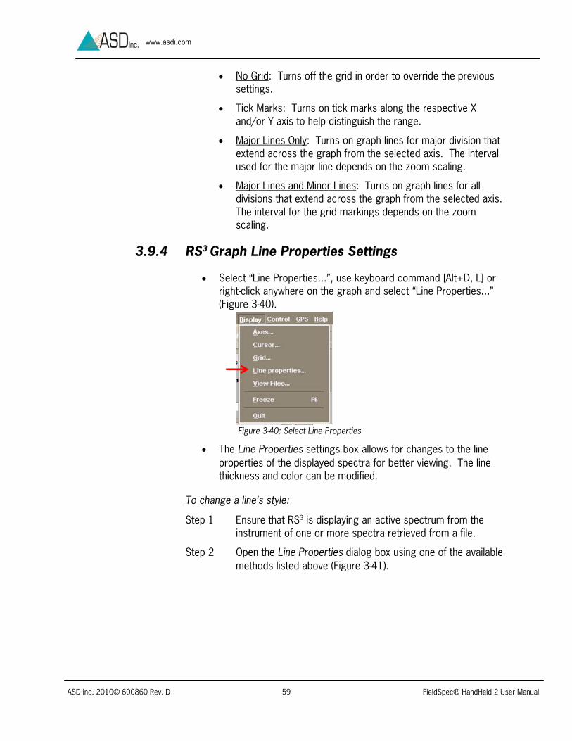
3.9.4 RS3 Graph Line Properties Settings
Select “Line Properties...”, use keyboard command [Alt+D, L] or right-click anywhere on the graph and select “Line Properties...” (Figure 3-40).
The Line Properties settings box allows for changes to the line properties of the displayed spectra for better viewing. The line thickness and color can be modified.
To change a line’s style:
Step 1 Ensure that RS3 is displaying an active spectrum from the instrument of one or more spectra retrieved from a file.
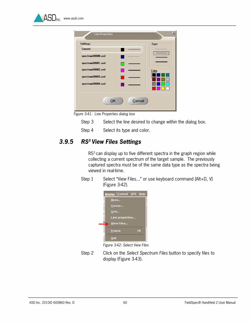
Step 2 Open the Line Properties dialog box using one of the available methods listed above (Figure 3-41).
Figure 3-40: Select Line Properties
ASD Inc. 2010© 600860 Rev. D 60 FieldSpec® HandHeld 2 User Manual
www.asdi.com
Figure 3-41: Line Properties dialog box
Step 3 Select the line desired to change within the dialog box.
Step 4 Select its type and color.
3.9.5 RS3 View Files Settings
RS3 can display up to five different spectra in the graph region while collecting a current spectrum of the target sample. The previously captured spectra must be of the same data type as the spectra being viewed in real-time.
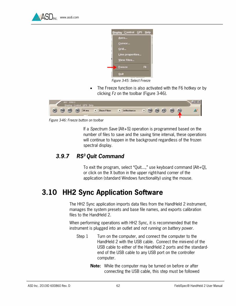
Step 1 Select “View Files...” or use keyboard command [Alt+D, V] (Figure 3-42).
Figure 3-42: Select View Files
Step 2 Click on the Select Spectrum Files button to specify files to display (Figure 3-43).

ASD Inc. 2010© 600860 Rev. D 61 FieldSpec® HandHeld 2 User Manual
www.asdi.com
Figure 3-43: Dialog box to view several spectra at once
Step 3 Select up to five files to view—or click on the Select All check box—then press the OK button (Figure 3-44).
Note: To change the files to view type, remove all the files in the View Files display box and then change the Y Axis type. For better viewing and differentiating of the spectra, change the line properties of the graphs.
Refer to section 3.9.4 RS3 Graph Line Properties Settings
3.9.6 RS3 Freeze Display Settings
The Freeze function is a toggle to allow the current spectra to be held in place or released to real-time viewing. At this point, the spectra can be compared with other stored spectra files.
Select “Freeze” (Figure 3-45) or use keyboard command [Alt+D, F].
Figure 3-44: Select files to view
ASD Inc. 2010© 600860 Rev. D 62 FieldSpec® HandHeld 2 User Manual
www.asdi.com
The Freeze function is also activated with the F6 hotkey or by clicking Fz on the toolbar (Figure 3-46).
If a Spectrum Save [Alt+S] operation is programmed based on the number of files to save and the saving time interval, these operations will continue to happen in the background regardless of the frozen spectral display.
3.9.7 RS3 Quit Command
To exit the program, select “Quit...,” use keyboard command [Alt+Q], or click on the X button in the upper right-hand corner of the application (standard Windows functionality) using the mouse.
3.10 HH2 Sync Application Software The HH2 Sync application imports data files from the HandHeld 2 instrument, manages the system presets and base file names, and exports calibration files to the HandHeld 2.
When performing operations with HH2 Sync, it is recommended that the instrument is plugged into an outlet and not running on battery power.
Step 1 Turn on the computer, and connect the computer to the HandHeld 2 with the USB cable. Connect the mini-end of the USB cable to either of the HandHeld 2 ports and the standard-end of the USB cable to any USB port on the controller computer.
Note: While the computer may be turned on before or after connecting the USB cable, this step must be followed
Figure 3-45: Select Freeze
Figure 3-46: Freeze button on toolbar

ASD Inc. 2010© 600860 Rev. D 63 FieldSpec® HandHeld 2 User Manual
www.asdi.com
prior to turning on the HandHeld 2. Reversing these steps will result in Standalone Mode, rather than Tethered Mode.
Step 2 Turn on the HandHeld 2. The Tethered Mode message will appear on the display (Figure 3-47).
Step 3 Click on the HH2 Sync shortcut on the computer desktop.
The HH2 Sync introductory screen will appear for a few seconds. After a few seconds, the Select Action screen will appear (Figure 3-48).
Figure 3-48: HH2 Sync Select Action screen
Step 4 Click on the Connect button to initiate communications with the HandHeld 2 instrument.
If the system is configured properly, a status window will appear for roughly 20 seconds while the connection is made. When the connection is made, the Connection Status will read “Connected”.
Tethered Mode
Figure 3-47: Instrument Tethered Mode display
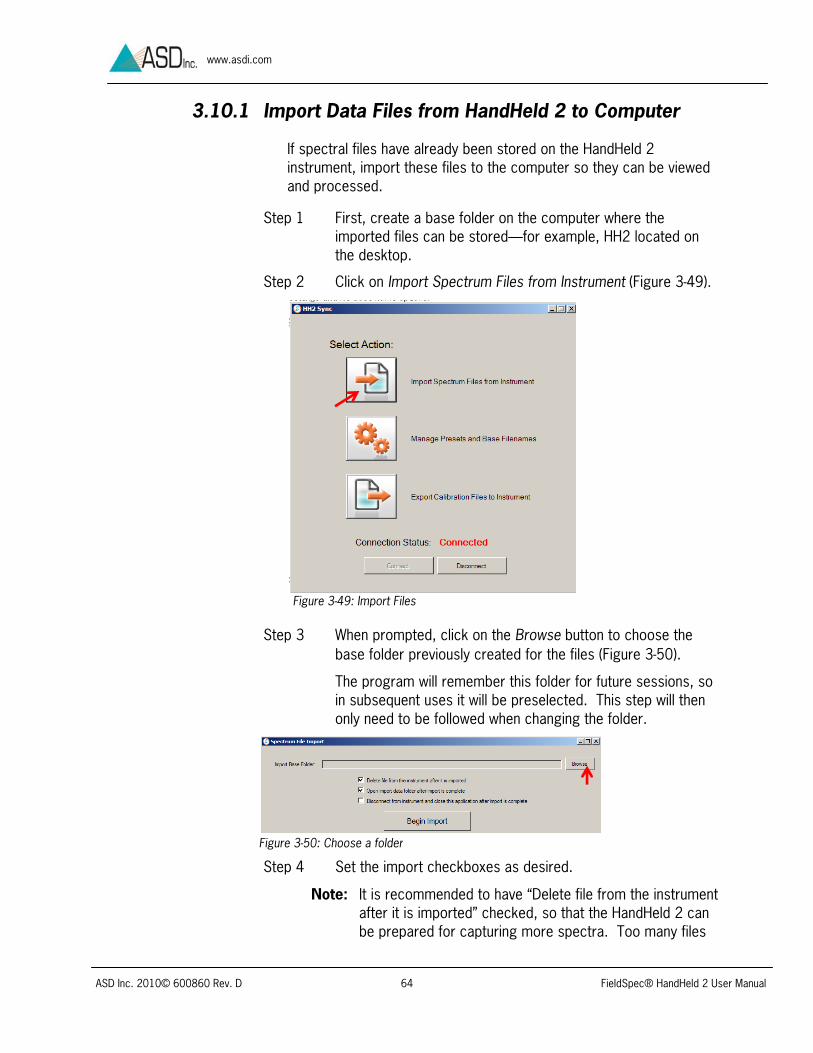
ASD Inc. 2010© 600860 Rev. D 64 FieldSpec® HandHeld 2 User Manual
www.asdi.com
3.10.1 Import Data Files from HandHeld 2 to Computer
If spectral files have already been stored on the HandHeld 2 instrument, import these files to the computer so they can be viewed and processed.
Step 1 First, create a base folder on the computer where the imported files can be stored—for example, HH2 located on the desktop.
Step 2 Click on Import Spectrum Files from Instrument (Figure 3-49).
Step 3 When prompted, click on the Browse button to choose the base folder previously created for the files (Figure 3-50).
The program will remember this folder for future sessions, so in subsequent uses it will be preselected. This step will then only need to be followed when changing the folder.
Step 4 Set the import checkboxes as desired.
Note: It is recommended to have “Delete file from the instrument after it is imported” checked, so that the HandHeld 2 can be prepared for capturing more spectra. Too many files
Figure 3-49: Import Files
Figure 3-50: Choose a folder

ASD Inc. 2010© 600860 Rev. D 65 FieldSpec® HandHeld 2 User Manual
www.asdi.com
stored on the instrument may adversely affect its responsiveness.
It is also recommended to have “Disconnect from instrument and close this application after import is complete” checked if HH2 Sync will not be further used after the import is complete. This ensures that HH2 Sync properly disconnects from the instrument following completion of task.
Step 5 Click on the Begin Import button.
As the files are being imported, a screen will display the filenames and the total number of files that have been imported. Each time an import is performed, the imported files will be saved into a new folder that is automatically created underneath the base folder chosen in Step 3 above. The new folder is named by the date and time that the import began.
When the import is complete an “Import Complete” message will appear, and if the second box was checked, the data folder that HH2 Sync created will automatically open in Windows Explorer to show the imported data (Figure 3-51).
Figure 3-51: Imported files
Step 6 If the HH2 Sync program is still running and no longer needs to be used, close the HH2 Sync program, or click the Disconnect button before shutting off the instrument or disconnecting the USB cable.
Note: To ensure that all file deletions, additions, or changes are saved, never shut off the instrument or disconnect the USB cable while the HH2 Sync program says it is “Connected.”
Step 7 Now use ViewSpec Pro to view and post-process the imported spectrum files (Refer to Section 3.11).
3.10.2 HandHeld 2 Instrument Presets and Filenames
Section 2.12.1 System Presets referred to the system presets, which can be created in order to program the device’s most

ASD Inc. 2010© 600860 Rev. D 66 FieldSpec® HandHeld 2 User Manual
www.asdi.com
commonly used instrument configurations, including basic instrument control settings and file base name options. Some settings cannot be changed through the instrument’s menus except by using presets. Time spent programing good presets and base filenames in HH2 Sync can greatly reduce the amount of time spent configuring the instrument in the field.
Note: All the fields in the “Plot Limits” box, and also the “Absolute Reflectance” checkbox can only be modified on the instrument through the use of presets. If in the field with the instrument, the plot limits will not be modifiable nor will absolute reflectance be accessible unless a preset with the desired setting is stored ahead of time.
Step 1 To adjust these presets, click on Manage Instrument Presets and Base Filenames (Figure 3-52).
Step 2 If this is the first time this operation has been performed, a warning will indicate the need to select the correct asdcfg.ini file. Click on the OK button (Figure 3-53).
Figure 3-53: asdcfg.ini warning
Step 3 Unless the default folder was changed when installing RS3, navigate to the asdcfg.ini file located in folder C:\Documents
Figure 3-52: Presets button

ASD Inc. 2010© 600860 Rev. D 67 FieldSpec® HandHeld 2 User Manual
www.asdi.com
and Settings\All Users\Application Data\ASD\RS3 (Figure 3-54).
Figure 3-54: Folder for asdcfg.ini
Step 4 Select the asdcfg.ini file in the RS3 folder and click Open (Figure 3-55).
Step 5 If this is the first time performing this operation, a warning message will indicate the need to select the File pull-down menu in order to either open an existing preset or to create a new preset in the next window (Figure 3-56). Click OK.
Step 6 If this is the first time entering presets, click on New (Figure 3-57). If a preset file has previously been editted, a prompt will ask if that same file is to be opened again.
Figure 3-55: Select the asdcfg.ini file
Figure 3-56: Existing or new file warning
Figure 3-57: New preset

ASD Inc. 2010© 600860 Rev. D 68 FieldSpec® HandHeld 2 User Manual
www.asdi.com
Note: When the ASD Applications Software on the computer is first installed, no pre-existing presets are provided with HH2 Sync. However, in Standalone Mode, the HandHeld 2 instrument has its own initial internal preset which cannot be modified or deleted. It is called “Default”. This preset is stored in the HandHeld 2 instrument and is not available to the external computer. The export of new presets is a one-way process from the computer running HH2 Sync to the HandHeld 2 instrument.
Step 7 Click on the Add/Copy button (Figure 3-58).
Step 8 Create a preset by typing in any new name for a preset with either letters and/or numerals (Figure 3-59). Then click on the OK button.
Figure 3-59: Make individualized preset
Figure 3-58: Add new preset

ASD Inc. 2010© 600860 Rev. D 69 FieldSpec® HandHeld 2 User Manual
www.asdi.com
The new preset is created and most typical settings are automatically filled into the fields (Figure 3-60).
Figure 3-60: New preset is created
Step 9 Modify the preset settings to best fit the application. Later, when this preset file has been exported to the instrument, the instrument can be configured to use all the settings selected here by simply choosing this preset name.
Step 10 Create additional presets as desired. Up to nineteen presets may be in a single preset file. Create a preset for any instrument configuration which may be useful when collecting data in Standalone Mode.
For example, a preset where all the spectrum counts are 1 may be useful. Figure 3-61 shows a preset called “SingleSpec” with this configuration. This preset eliminates the need to navigate the on-screen menus in Standalone Mode in order to change all three counts.

ASD Inc. 2010© 600860 Rev. D 70 FieldSpec® HandHeld 2 User Manual
www.asdi.com
If a preset similar to an existing preset is desired, highlight the existing preset in the list when clicking Add/Copy. The new preset will be created as a copy of the existing one, and then the fields can easily be modified to fit with new specifications.
Step 11 At the bottom of this screen, base filenames can be set up in order to be exported to the instrument. Creating base filenames here allows the user to type in base filenames using the keyboard instead of using the HandHeld 2. Later, in Standalone Mode, the filenames created here can be selected from a list on the instrument.
Step 12 To add a new base filename, click on the Add button.
Step 13 Type in a base filename, such as “Sample” (Figure 3-62). Select OK.
Note: On the instrument, changing the selected preset does not change the selected base filename. The two are selected independently of each other.
Figure 3-61: ”SingleSpec” preset with all Spectrum Counts as 1

ASD Inc. 2010© 600860 Rev. D 71 FieldSpec® HandHeld 2 User Manual
www.asdi.com
Step 12 Under the File pull-down menu, select “Save” or “Save As…“.
Step 13 When prompted, navigate to the ASD folder created when the ASD Applications Software was installed— C:\Documents and Settings\All Users\Application Data\ASD (Figure 3-63).
Step 14 Click on the ASD folder to open it and save the new default preset to this folder. Also enter the new name for this file.
Step 15 The preset can is now ready to be exported to the HandHeld 2 instrument. Under the File pull-down menu, click on Export (Figure 3-64).
3.10.3 Export Calibration Files to HandHeld 2 Instrument
The last button in the HH2 Sync Select Action window is Export Calibration Files to Instrument. Whenever any calibration files have been updated, use this button to export those files from the computer to the HandHeld 2 Instrument.
Step 1 Click “Export Calibration Files to Instrument” (Figure 3-65).
Figure 3-62: New base filename
Figure 3-63: ASD Folder
Figure 3-64: Export

ASD Inc. 2010© 600860 Rev. D 72 FieldSpec® HandHeld 2 User Manual
www.asdi.com
Step 2 Navigate to the RS3 folder and select the files to be exported. Click OK for the export to take place (Figure 3-66).
Figure 3-66: Calibration files in RS3 folder
3.10.4 Disconnect HH2 Sync
It is recommended to always disconnect HH2 Sync from the instrument before disconnecting the USB cable conjoining the computer to the instrument, or before turning off the instrument. Avoid disconnecting the USB cable or turning off the instrument while HH2 Sync says it is connected to the instrument.
Note: Closing HH2 Sync without disconnecting is acceptable, as it will automatically disconnect from the instrument.
3.11 ViewSpec Pro Post-Processing Software Click on the ViewSpec Pro shortcut to open the ViewSpec Pro post-
processing application (Figure 3-67).
Figure 3-65: Export Calibrations

ASD Inc. 2010© 600860 Rev. D 73 FieldSpec® HandHeld 2 User Manual
www.asdi.com
Figure 3-67: ViewSpec Pro shortcut
Or from the Start menu select All ProgramsASD ProgramsViewSpecPro.
The ViewSpec Pro working window will appear. Click the Help pull-down menu and select the User’s Guide for more information (Figure 3-68).
A PDF format document of the ViewSpec Pro manual gives complete instructions on using the ViewSpec Pro post-processing software on ASD spectral data files.
3.12 GPS When connected to the HandHeld 2 or the controller computer, a GPS will provide geographic coordinates that will be saved within each corresponding spectral file. The GPS offered with the HandHeld 2 mounts magnetically to the top of the instrument in order to simplify use in the field. The HandHeld 2 may also operate with other GPS models, however, these devices must meet NMEA 0183 GGA specifications.
Although the GPS may be used with the HandHeld 2 in both Tethered and Standalone Modes, the procedures differ. As explained in the Chapter 2 introduction, Standalone Mode uses only the internal control and data collection capabilities of the HandHeld 2, while Tethered Mode combines the capabilities of the HandHeld 2 with the power of an external controller computer.
A GPS log lists all of the coordinates in a text file. It can be created in real-time in Tethered Mode using RS3 software. In Standalone Mode, creating a GPS log requires post-processing with ViewSpec Pro.
Note: In each of these modes, the GPS interfaces with the system in a unique way. In Tethered Mode, the GPS must be plugged into the computer. In contrast, the GPS must be plugged into the HandHeld 2 when in Standalone Mode.
Figure 3-68: ViewSpec Pro window and Users Guide
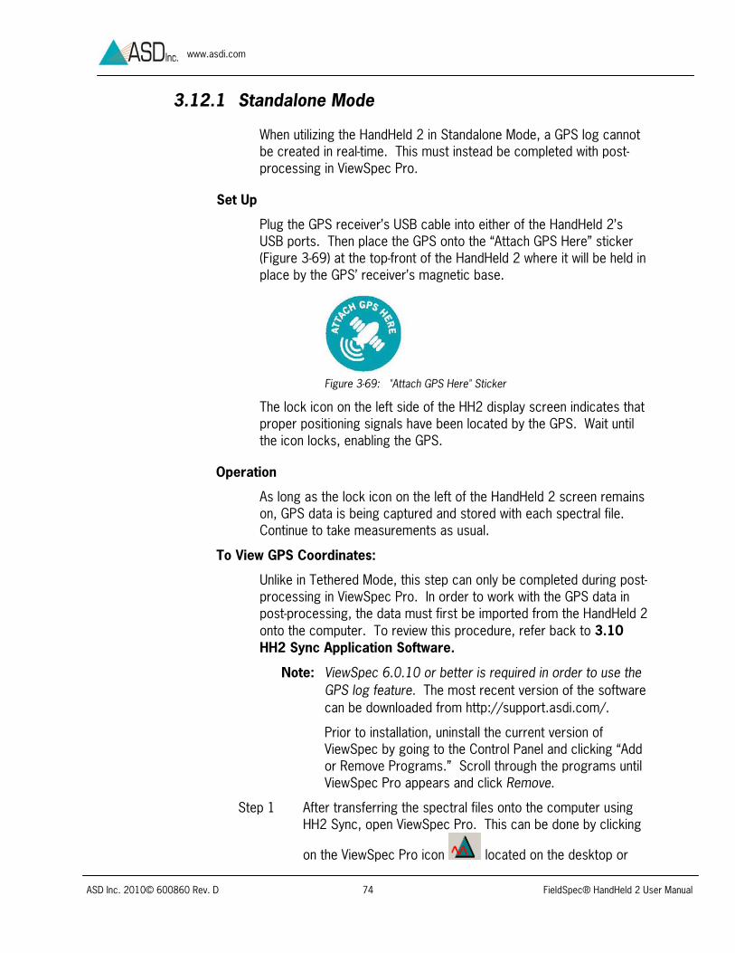
ASD Inc. 2010© 600860 Rev. D 74 FieldSpec® HandHeld 2 User Manual
www.asdi.com
3.12.1 Standalone Mode
When utilizing the HandHeld 2 in Standalone Mode, a GPS log cannot be created in real-time. This must instead be completed with post-processing in ViewSpec Pro.
Set Up
Plug the GPS receiver’s USB cable into either of the HandHeld 2’s USB ports. Then place the GPS onto the “Attach GPS Here” sticker (Figure 3-69) at the top-front of the HandHeld 2 where it will be held in place by the GPS’ receiver’s magnetic base.
Figure 3-69: "Attach GPS Here" Sticker
The lock icon on the left side of the HH2 display screen indicates that proper positioning signals have been located by the GPS. Wait until the icon locks, enabling the GPS.
Operation
As long as the lock icon on the left of the HandHeld 2 screen remains on, GPS data is being captured and stored with each spectral file. Continue to take measurements as usual.
To View GPS Coordinates:
Unlike in Tethered Mode, this step can only be completed during post-processing in ViewSpec Pro. In order to work with the GPS data in post-processing, the data must first be imported from the HandHeld 2 onto the computer. To review this procedure, refer back to 3.10 HH2 Sync Application Software.
Note: ViewSpec 6.0.10 or better is required in order to use the GPS log feature. The most recent version of the software can be downloaded from http://support.asdi.com/.
Prior to installation, uninstall the current version of ViewSpec by going to the Control Panel and clicking “Add or Remove Programs.” Scroll through the programs until ViewSpec Pro appears and click Remove.
Step 1 After transferring the spectral files onto the computer using HH2 Sync, open ViewSpec Pro. This can be done by clicking
on the ViewSpec Pro icon located on the desktop or

ASD Inc. 2010© 600860 Rev. D 75 FieldSpec® HandHeld 2 User Manual
www.asdi.com
through the Start Menu, by selecting All Programs ADS Programs ViewSpec Pro.
Step 2 Click the File pull-down menu, and select Open.
Step 3 Navigate to the folder of the spectral data and select all files to be added into the GPS log. Press Open (Figure 3-70).
Figure 3-70: Select Input File(s)
Step 4 Click the View pull-down menu, and select “Header Info.”
Step 5 To view GPS data, click on the GPS tab (Figure 3-71).
Figure 3-71: Header Information
To Create a GPS Log:
Step 1 First follow steps 1-3 of the previous procedure, To View GPS Coordinates.
Step 2 Select all of the files [Shift+click] and click the Process pull-down menu. From here, select GPS Log (Figure 3-72).

ASD Inc. 2010© 600860 Rev. D 76 FieldSpec® HandHeld 2 User Manual
www.asdi.com
Figure 3-72: Create GPS Log
Step 3 Choose a location in which to save the newly created GPS log (Figure 3-73).
Figure 3-73: GPS Log
To Retrieve a GPS Log:
The GPS log will be stored in the same folder as its corresponding spectra in the format <month><date><year>gps.log.
3.12.2 Tethered Mode
A GPS device plugs into one of the USB ports of the controller computer in order to communicate with RS3 software. If the GPS and the computer were either not purchased from ASD or purchased separately, follow the directions below to configure the device.
Note: In Tethered Mode, the GPS must be plugged directly into the controlling computer. GPS data will not be collected if connected to a HandHeld 2 running in Tethered Mode.
Set Up
Step 1 Plug the USB cable into one of the USB ports on the computer. If the GPS received is purchased with the HandHeld 2, ASD typically configures the USB port on the left side of the computer (while viewing the screen) for the GPS receiver. Once a USB port has been configured, it is recommended to always use this port. If changed, this entire process will need to be repeated.

ASD Inc. 2010© 600860 Rev. D 77 FieldSpec® HandHeld 2 User Manual
www.asdi.com
If the GPS or computer were not purchased from ASD, start the GPS receiver and go to the GPS receiver’s communication interface settings. This will typically be found under Main MenuSetupInterface. Choose the communication format that outputs NMEA text. Close the setup windows and allow the receiver to acquire a position fix.
Step 2 If the COM port assigned to the GPS has changed from the one set at ASD or if configuring for the first time, open the Windows Device Manager (Figure 3-74). The Device Manager can be accessed by clicking the StartControl PanelSystemHardwareDevice Manager. Note the port number (Example, COM4). This number will be necessary to remember for Step 4.
Figure 3-74: Device manager
Step 3 Open RS3, click on the GPS pull-down menu and select “Settings…” (Figure 3-75).
Figure 3-75: GPS pull-down menu
Step 4 Under “Port,” select the port number which was viewed under the Device Manager (Figure 3-76).
Also select the proper Baud rate, as listed in the GPS receiver’s specific user manual. Normally, the Data bits, Parity and Stop bits settings will remain the same as what is displayed in the image below.
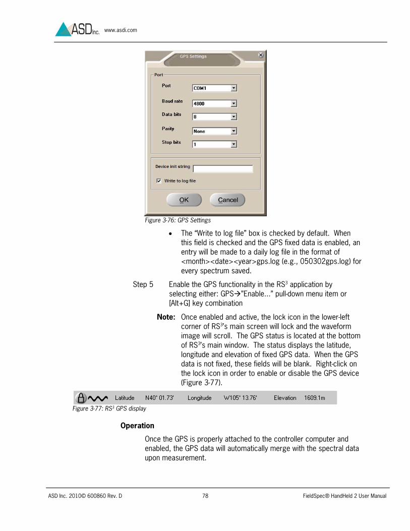
ASD Inc. 2010© 600860 Rev. D 78 FieldSpec® HandHeld 2 User Manual
www.asdi.com
Figure 3-76: GPS Settings
The “Write to log file” box is checked by default. When this field is checked and the GPS fixed data is enabled, an entry will be made to a daily log file in the format of <month><date><year>gps.log (e.g., 050302gps.log) for every spectrum saved.
Step 5 Enable the GPS functionality in the RS3 application by selecting either: GPS”Enable...” pull-down menu item or [Alt+G] key combination
Note: Once enabled and active, the lock icon in the lower-left corner of RS3’s main screen will lock and the waveform image will scroll. The GPS status is located at the bottom of RS3’s main window. The status displays the latitude, longitude and elevation of fixed GPS data. When the GPS data is not fixed, these fields will be blank. Right-click on the lock icon in order to enable or disable the GPS device (Figure 3-77).
Figure 3-77: RS3 GPS display
Operation
Once the GPS is properly attached to the controller computer and enabled, the GPS data will automatically merge with the spectral data upon measurement.

ASD Inc. 2010© 600860 Rev. D 79 FieldSpec® HandHeld 2 User Manual
www.asdi.com
If desired, a GPS log can be created either in real-time using the RS3
or in post-processing using ViewSpec Pro.
To Create a GPS Log in Real-Time:
Once the GPS is enabled, a GPS log can be created in real-time.
Step 1 Click the GPS pull-down menu [Alt+G] within RS3’s main window and select “Settings.”
Step 2 Click the “Write to log file” checkbox (Figure 3-76). All following measurements will now have their corresponding GPS location saved in this file.
To View GPS Coordinates:
To view GPS coordinates of each spectral file, one must use ViewSpec Pro post-processing.
Note: ViewSpec 6.0.10 or better is required in order to use the GPS log feature.
Step 1 Open ViewSpec Pro by clicking on the ViewSpec Pro icon
located on the desktop or through the Start Menu, by selecting All Programs ADS Programs ViewSpec Pro.
Step 2 Click the File pull-down menu, and select Open.
Step 3 Navigate to the folder of the spectral data and select all files to be viewed. Press Open.
Step 4 Click the View pull-down menu, and select “Header Info.”
Step 5 To view GPS data, click on the GPS tab.
To Create a GPS Log in Post-Processing:
If “Write to log file” was not checked in RS3 at the time of measurement, it will be necessary to perform the following steps in ViewSpec Pro post-processing in order to create a GPS log.
Step 1 First follow steps 1-3 of the previous procedure, To View GPS Coordinates.
Step 2 Select all of the files (Shift+click) and click the Process pull-down menu. From here, select GPS Log.
Step 3 Choose a location in which to save the newly created GPS log.
To Retrieve a GPS Log:
The GPS log will be stored in the same folder as its corresponding spectra in the format <month><date><year>gps.log.

ASD Inc. 2010© 600860 Rev. D 80 FieldSpec® HandHeld 2 User Manual
www.asdi.com
Chapter 4 Maintenance & Trouble Shooting
4.1 Care and Cleaning of Spectralon® Spectralon is a product of LabSphere, Inc. and the following instructions are based on LabSphere’s instructions.
Spectralon is an optical standard and should be handled in much the same way as other optical standards. Although the material is very durable, care should be taken to prevent contaminants such as finger oils from contacting the material’s surface. Always wear clean gloves when touching Spectralon.
If the Spectralon is lightly soiled, it may be air brushed with a jet of clean dry air or nitrogen. Do not use any compressed gas in which Freon is used as the propellant. Freon will permanently discolor the Spectralon.
To clean a heavily soiled Spectralon:
Step 1 Remove the reference panel from the reference panel holder. To do so, unscrew the three hex screws (0.035 inch) two and a half turns.
Step 2 Place a flat surface, such as a thick piece of glass into the sink.
Step 3 Place 220 grade wet sandpaper onto the glass.
Step 4 Holding the edges of the sandpaper in place, gently rub the reference panel in a figure-eight motion over the paper until the panel is hydrophobic (water beads and runs off immediately).
Note: Be sure to follow these steps rather than setting the reference panel onto the glass and rubbing the sandpaper onto the panel—doing so will apply uneven pressure to the reference panel’s surface, thus creating areas of unequal reflectance.
Step 5 Use water as needed to wash away the thin layer which is sanded off.
Step 6 Blow dry with air or nitrogen, or allow the material to air dry for a minimum of 4 hours.

ASD Inc. 2010© 600860 Rev. D 81 FieldSpec® HandHeld 2 User Manual
www.asdi.com
Step 7 When returning the reference panel into the reference panel holder, be sure to press down near the hex screw location while tightening each screw.
If the material requires high resistance to deep UV radiation, the piece should be prepared as described above and then one of the following treatments should be performed:
1. Flush the Spectralon piece with > 18 milli-ohm distilled, deionized water for 24 hours.
2. Vacuum bake the Spectralon piece at 75° C for a 12 hour period at a vacuum of 1 Torr or less. Then purge the vacuum oven with clean dry air or nitrogen.
Note: DO NOT use oils or soaps to clean the white reference.
4.2 Care and Cleaning of HandHeld 2 instrument For safety reasons and to prevent damage to the instrument, please review all safety precautions in this manual.
Do not place objects on the unit or its power supplies. Keep objects and spills from entering or falling onto the instrument, power supplies, and software disks.
HandHeld 2 is designed to withstand some light splashes of water, although these conditions should always be avoided. If splashing should occur, shut down the instrument, remove the batteries and disconnect the power supplies. Allow the instrument to completely dry for a day. If the AC/DC power supply has been dropped in water, return it to an authorized dealer or service center for examination or repair.
CAUTION: Risk of Electric Shock. The HandHeld 2 instrument is NOT designed to be submersed.
To clean the instrument:
1. Turn off the unit.
2. Disconnect from all power.
3. Allow the instrument to cool down.
4. Clean the instrument with slightly damp cloth and mild soap. Be sure all soap residue is removed and all surfaces are dry before use.

ASD Inc. 2010© 600860 Rev. D 82 FieldSpec® HandHeld 2 User Manual
www.asdi.com
4.3 Care and Cleaning of HandHeld 2 Optical Input and Fore Optics
The HandHeld 2 instrument optical input is constructed from silica and the fore optic lenses are made from high quality BK7 glass. As with any optics, protect HandHeld 2 instrument optical input and fore optic lenses from scratches and dirt. Wipe with a slightly moist, clean cloth if necessary. Small scratches in the lens surface should not affect reflectance measurements significantly (or other unit-less ratio measurements).
As calibrations are strongly dependent on clear optics at the time of calibration, absolute energy radiometric calibrations are invalidated by broken or cloudy lenses. In this case, a new replacement and radiance calibration is required.
Keep water, dirt or small objects from getting inside a fore optic body or sticking to the front of the fore optic tube. An occasional check is recommended. Repair or replacement and re-calibration may be required if foreign objects get stuck inside.
The irradiance cosine collector may be cleaned like the lenses mentioned above. If the diffuser becomes too scratched or broken, a new replacement and irradiance calibration is required.
4.4 Care and Cleaning of the Laser Pointer Protect the laser pointer output lens from scratches and dirt. Wipe with a clean cloth whenever necessary.
CAUTION: Risk of danger. As with all high energy light sources, the laser can cause harm to eyes. Do not look directly into the laser output. For additional information on the proper use and safety practices of lasers, see the U.S. Department of Labor Occupational Safety & Health Administration OSHA Technical Manual which includes references to the applicable American National Standards Institute standards for safe laser use: http://www.osha.gov/dts/osta/otm/otm_iii/otm_iii_6.html.
4.5 Care and Cleaning of Optional Fiber Optic Jumper Cables
Although the fiber optic jumper cables are designed to withstand a variety of field uses, care should be taken to prevent excessive forces on the fragile glass fibers inside the durable cable jacket.

ASD Inc. 2010© 600860 Rev. D 83 FieldSpec® HandHeld 2 User Manual
www.asdi.com
Tips on care for fiber optic jumper cables:
The fiber optic jumper cable should never be stored with a bend diameter of less than a 5" diameter for long periods of time, the cable can be damaged with undetectable fractures that can cause decreased signals.
Do not use wires, ties, or clamps to tightly attach the fiber optic cable to objects, this may pinch or penetrate the protective jacket thereby damaging the fibers inside.
Avoid twisting, pulling, dropping, or slamming the fiber optic cable into objects. These actions can cause fractures to the glass fibers.
When to replace the fiber optic cable:
Small scratches in the input surface should not affect reflectance measurements significantly (or other ratio measurements). However, if the input surface becomes cloudy, the signal could be severely attenuated and a new replacement cable is recommended.
Broken fibers in the fiber optic bundle will attenuate the signal. The signal loss of one or two broken fibers may be tolerated in reflectance measurements in an emergency (or other unit-less ratio measurements). However, we strongly recommend replacing the cable with a new one as soon as possible.
Note: See the Fiber Optic Inspect Magnifier User Manual for further information on broken fibers.
Protect the tip of the fiber optic cable: While the tip of the fiber optic cable is not particularly susceptible to damage, a tip cover is recommended to protect against excessive abrasion and exposure to contamination. Replacement covers can be made by cutting pieces of eighth-inch shrink tubing to about 1.5" lengths and shrinking them onto the fiber optic cable tip. They will slide on and off the cable easily.
Clean the tip of the fiber optic cable: The input end of the fiber optic jumper cable consists of the polished ends of the glass fibers embedded in epoxy potting. Clean the input end with a damp cloth and either blow dry it, allow it to air-dry, or use a lint-free tissue/lens cleaning cloth. If necessary, isopropyl alcohol can also be used to clean the tip.
4.6 Care of Optional Light Sources We recommend that only light sources supplied by ASD Inc. are used with ASD instruments. Light sources supplied by ASD are designed to provide levels of illumination and stability of output that complement the performance of ASD instrumentation. To maintain the performance of the light sources:

ASD Inc. 2010© 600860 Rev. D 84 FieldSpec® HandHeld 2 User Manual
www.asdi.com
Prevent dirt and oils from contacting the bulb and reflector.
Do not touch the glass envelope of the bulb. Oils on the hand may transfer to the glass envelope—this can significantly affect the bulb temperature and corrupt important operating physics of the bulb.
Never touch the light source’s bulb and avoid contact with hot metal components near the bulb. Heat transfer from the light source may make these metal components uncomfortably warm to the touch.
4.7 Temperature Effects The operating temperature range of the HandHeld 2 instrument is 0° to 40° C (32° to 104° F). If the HandHeld 2 instrument is exposed to intense direct sunlight or is exposed to ambient temperature outside the operating range, the internal temperature of the HandHeld 2 instrument may reach a point that could shorten the operating period. If the display fades or flickers or shows obvious errant spectra the system might be failing due to extreme temperature. Shut down and let the instrument cool or warm before operating again.
4.8 W.E.E.E. Compliance ASD, Inc. supports the Waste Electrical and Electronic Equipment Directive (W.E.E.E.). ASD marks the instruments with the symbol at the left to show that this product has entered the market place after August 13, 2005.
When the spectrometer reaches the end of its useful life, please do not discard it as general waste. ASD will accept the return of the instrument for recycling. Contact ASD Customer Service to arrange for return of the instrument.
4.9 Annual Factory Maintenance ASD recommends that the instrument be serviced once a year at the factory (or authorized factory service depot). This will ensure the proper function of the instrument. One performance check and re-calibration is covered under ASD's warranty or an optional extended warranty may be purchased.
Note: The customer must send the HandHeld 2 into the ASD factory for service.

ASD Inc. 2010© 600860 Rev. D 85 FieldSpec® HandHeld 2 User Manual
www.asdi.com
4.10 Sending Instrument to ASD for Service For instructions on sending the instrument to ASD for service, please contact the Technical Support Department.
4.11 Technical Support If there are any questions or concerns, please contact ASD Inc. by phone, fax, or email:
Phone: 303-444-6522 Ext-144 Fax: 303-444-6825 E-mail: [email protected] Main Web Site: www.asdi.com Support portal: http://support.asdi.com/
Technical support is committed to providing a timely response to all questions. Technical support is available to answer questions Monday through Friday, 8 am to 5 pm Mountain Standard Time. We will respond to e-mail queries as well.
When contacting ASD Technical Support please have the instrument model and serial number, located on a label on the bottom of the HandHeld 2 instrument, available (Figure 4-1).
Figure 4-1: HandHeld 2 instrument model and serial number label
The serial number is also accessible in the ASD applications software from the splash screen or the HelpAbout menu item.
4.12 Trouble Shooting
4.12.1 Communication Errors
To fix many communication errors, power cycle the instrument and/or the instrument controller. The sequence will vary depending on the computer manufacturer. Either:
Leave the computer on. Turn off the instrument. Wait for 10 seconds. Turn the instrument back on.

ASD Inc. 2010© 600860 Rev. D 86 FieldSpec® HandHeld 2 User Manual
www.asdi.com
Or, turn off the computer and the instrument. Turn on the instrument. Then turn on the instrument controller.
4.12.2 Unusual or Excessive Noise
Noise can be caused by many phenomena. Read through the following subsections to discover which may be affecting the system.
Noise Due to Light Source
Significant changes in noise level can result from changes in illumination distance and angle. For artificial light sources, check and compare the set-up of the lamp from previous measurements. For solar illumination, check and compare the conditions present during the previous collection such as atmospheric conditions, time of day, seasons, etc.
An alternating current powered lamp can produce a sine wave pattern in the spectra. Noise or large spikes can occur in the data when using a low pressure gas emitter lamp, such as a fluorescent light. When working with artificial illumination, always use a direct current (DC) powered lamp. Tungsten quartz halogen is preferred due to the good transmission of the quartz envelope and long term stability of the filament due to the halogen gas inside the envelope.
If a lamp reflector or cover glass has two parallel or coated surfaces, interference fringes can occur, appearing as sine waves in the signal. The solution is to remove the glass and/or use a more diffuse reflector.
Noise Due to the Fiber Optic Cable
If using a fiber optic jumper cable, the signal will be reduced at the jumper junction by as much as 50%. Therefore, the random noise will be higher when using a fiber optic jumper cable compared to the bare input.
Broken fibers in a fiber optic jumper cable can contribute to noise. Perform a fiber optic check to verify. This can be done by pointing one end of the fiber optic jumper cable at a safe light source so as to not cause damage to the eyes. Count the fibers on the other end by viewing with a magnifying lens. Most ASD VNIR type jumper cables have 19 fibers and all fibers should appear illuminated in a fully functional fiber optic jumper cable.

ASD Inc. 2010© 600860 Rev. D 87 FieldSpec® HandHeld 2 User Manual
www.asdi.com
Note: A Fiber Optic Inspect Magnifier (Product Number A121065) can be purchased to simplify this process, allowing the user to magnify the cable.
Noise Due to the Instrument
An increase in noise can be due to a problem in the instrument, such as an electronic component malfunction or a grounding problem. This may be indicated by a regular pattern to the noise or periodic bursts of noise that are visible over the normal spectra.
When the spectrum drops to zero after a dark current has been collected, this may indicate a problem with the shutter or dark current collection routine. To verify, optimize the instrument and listen for the click of the shutter activating. If the shutter click cannot be heard, contact technical support and obtain an RMA for sending the instrument in for repair.
4.12.3 Background Interference
If the field-of-view spot size is larger than the sample or white reference panel such that unwanted background is entering the field-of-view, move closer to the sample or white reference panel. The field-of-view is conical-shaped, so moving it closer to the sample produces a smaller spot size.
If closer measurements are not practical, it may be necessary to acquire a larger white reference panel or a fore optic with a smaller field-of-view. Contact a sales representative to learn which fore optic will best suit the instrument’s application.
4.12.4 Software Problems
To ensure accuracy in the collection and processing of data, RS3
software in Tethered Mode is designed to finish its current operation before moving on to the next routine. Do not rush into issuing new commands until the results of the current command can be seen.
Non-ASD applications which can interfere with the ASD software are utility programs, network programs and those working in the background, such as virus checkers. ASD programs require real-time access to the data that is being streamed from the HandHeld 2 instrument at a high rate of speed. Programs running in the background can cause packets to be lost.
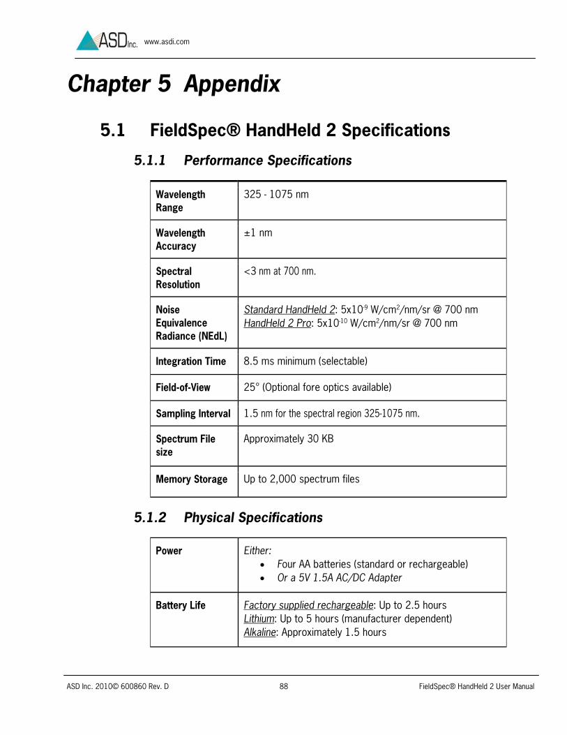
ASD Inc. 2010© 600860 Rev. D 88 FieldSpec® HandHeld 2 User Manual
www.asdi.com
Chapter 5 Appendix
5.1 FieldSpec® HandHeld 2 Specifications
5.1.1 Performance Specifications
Wavelength Range
325 - 1075 nm
Wavelength Accuracy
±1 nm
Spectral Resolution
<3 nm at 700 nm.
Noise Equivalence Radiance (NEdL)
Standard HandHeld 2: 5x10⁻⁹ W/cm2/nm/sr @ 700 nm HandHeld 2 Pro: 5x10⁻¹⁰ W/cm2/nm/sr @ 700 nm
Integration Time 8.5 ms minimum (selectable)
Field-of-View 25° (Optional fore optics available)
Sampling Interval 1.5 nm for the spectral region 325-1075 nm.
Spectrum File size
Approximately 30 KB
Memory Storage Up to 2,000 spectrum files
5.1.2 Physical Specifications
Power Either: Four AA batteries (standard or rechargeable) Or a 5V 1.5A AC/DC Adapter
Battery Life
Factory supplied rechargeable: Up to 2.5 hours Lithium: Up to 5 hours (manufacturer dependent) Alkaline: Approximately 1.5 hours

ASD Inc. 2010© 600860 Rev. D 89 FieldSpec® HandHeld 2 User Manual
www.asdi.com
Built-In Display 6.8 cm (2.7 in. diagonal) color a-Si TFT LCD, QVGA [240 (H) x 320 (V)] total pixel count
Interfaces One Mini Type B USB (PC communications), One Mini TRS Jack (Remote trigger), Two Type A USB, DC Input Power
Computer Software
RS3™ Controlling Software, ViewSpec Pro™ Post Processing Software, HH2 Sync Interface Software
Weight 1.2 kg (2.6 lbs.) with batteries
Body Dimensions Measurements with handle not attached (width x depth x height): 90 x140 x 215 mm (3.5 x 5.5 x 8.5 in)
Temperature Range
Operating Temperature: 0° to 40° C (32° to 104° F) Storage Temperature: 0°C to 45°C (32° to 113° F) Operating and Storage Humidity: 90% Non-condensing
Tripod Mount ¼ inch -20 Mounting Hole
5.2 Optional Controller Computer Specifications The standard HandHeld 2 instrument does not include as standard an external controller computer. An external computer may be purchased separately from ASD or provided by the customer.
The minimum requirements for the external controller computer are:
1.2 GHz Pentium or better notebook or PC-w/monitor
256 MB RAM or more
20 GB of free disk space
1024 x 768 or better graphics resolution
24-bit color or better - 32-bit recommended
USB port for Tethered Mode, as well as for the optional GPS receiver.
(Optional) NMEA compatible GPS receiver
The minimum requirements for the controller computer software are:
RS3 Software from ASD
Microsoft Windows® XP/Vista/7 Operating System

ASD Inc. 2010© 600860 Rev. D 90 FieldSpec® HandHeld 2 User Manual
www.asdi.com
Microsoft Internet Explorer 6.0 or better
Users need a basic understanding of the Microsoft Windows operating system, including software installation.
International customers using non-English versions of Windows must alter the Regional Settings under StartSettingsControl Panel. The default language must be set to English (United States) in order for the software to be registered and to operate correctly. The numbering format must also be set to English.
5.3 Spare Parts Occasionally it may be necessary to replace the standard accessories of the HandHeld 2 unit. In this case, contact a sales representative. The product numbers below will help to expedite this process.
Accessory Product Number
7.2 V HandHeld™ 2 Rechargeable Battery 145103 Lithium Ion Battery Charger A145112 15V, 30 Watt Power Supply (for Battery Charger) A146521 Power Supply Assembly for HandHeld™ 2 A146511
5.4 Optional Accessories ASD offers a variety of accessories to allow convenient measurements within various applications. For further information on the function of each accessory, contact an ASD sales representative.
Figure 5-6: From Left to Right; HandHeld 2 with Spotting Sight, Plant Probe with Leaf Clip, and Tripod
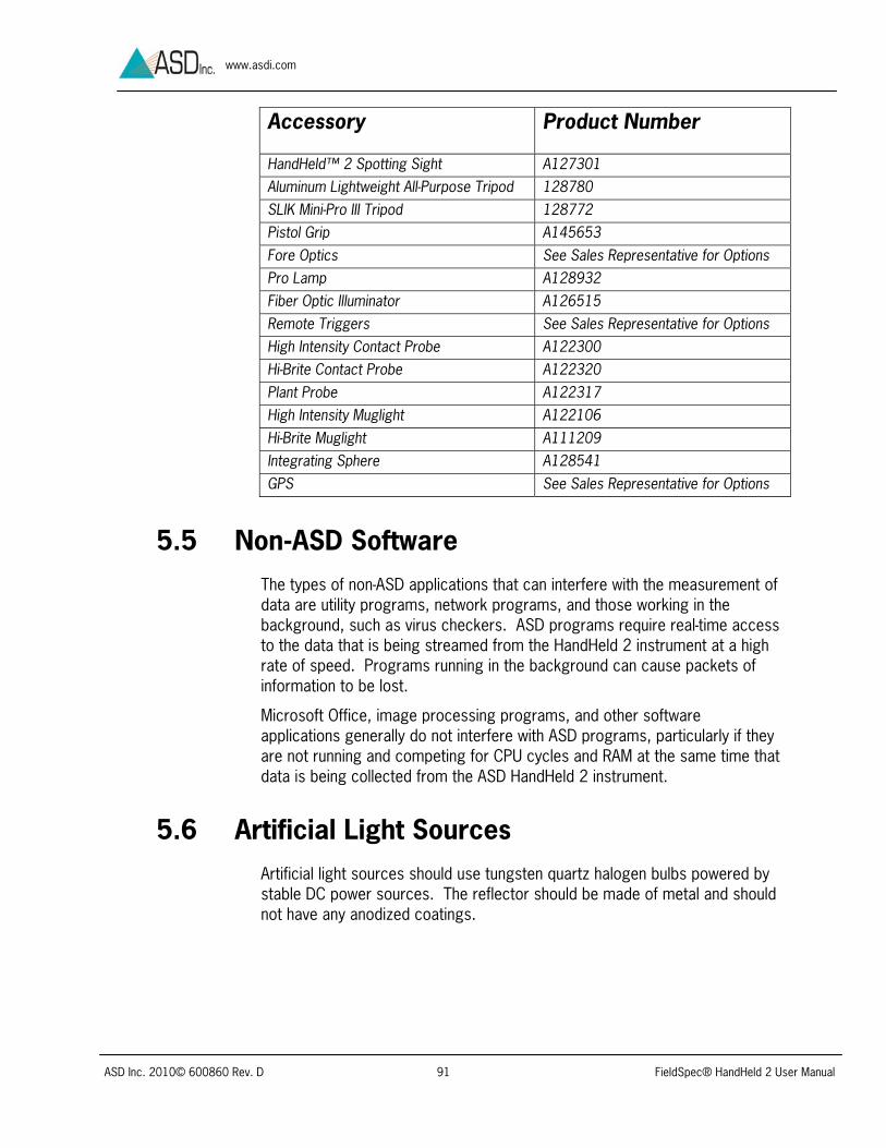
ASD Inc. 2010© 600860 Rev. D 91 FieldSpec® HandHeld 2 User Manual
www.asdi.com
Accessory Product Number
HandHeld™ 2 Spotting Sight A127301 Aluminum Lightweight All-Purpose Tripod 128780 SLIK Mini-Pro III Tripod 128772 Pistol Grip A145653 Fore Optics See Sales Representative for Options Pro Lamp A128932 Fiber Optic Illuminator A126515 Remote Triggers See Sales Representative for Options High Intensity Contact Probe A122300 Hi-Brite Contact Probe A122320 Plant Probe A122317 High Intensity Muglight A122106 Hi-Brite Muglight A111209 Integrating Sphere A128541 GPS See Sales Representative for Options
5.5 Non-ASD Software The types of non-ASD applications that can interfere with the measurement of data are utility programs, network programs, and those working in the background, such as virus checkers. ASD programs require real-time access to the data that is being streamed from the HandHeld 2 instrument at a high rate of speed. Programs running in the background can cause packets of information to be lost.
Microsoft Office, image processing programs, and other software applications generally do not interfere with ASD programs, particularly if they are not running and competing for CPU cycles and RAM at the same time that data is being collected from the ASD HandHeld 2 instrument.
5.6 Artificial Light Sources Artificial light sources should use tungsten quartz halogen bulbs powered by stable DC power sources. The reflector should be made of metal and should not have any anodized coatings.

ASD Inc. 2010© 600860 Rev. D 92 FieldSpec® HandHeld 2 User Manual
www.asdi.com
Index
Batteries ............................................ 11 Battery Charger ............................... 11 Battery Polarity ................................ 14
Carrying Case .................................... 10 Configuration Files .............................. 42 Connector Cover ................................ 13 Coordinate Mode ................................ 57 Copyright Information ............................ 6 Dark Current ...................................... 22 DC/WR .............................................. 23 Declaration of Conformity ...................... 7 Disclaimer ............................................ 6 Display Panel ...................................... 16 Export Data
Calibration Files ............................... 71 File Save Menu ................................... 31
Create a New Base Name ................. 33 Number to Save ............................... 36 Open an Existing Base Name ............ 32 Save Interval.................................... 37 Starting ID ....................................... 35 System Menu .................................. 38
Foreoptics Maintenance .................................... 82
FTDI Driver ......................................... 42 GPS ................................................... 73 Hand Strap ......................................... 12 Handle ......................................... 11, 12 HH2 Sync
Import Data ..................................... 64 Installation ....................................... 42 Procedure ....................................... 62
Illumination ......................................... 18 Requirements .................................. 91 Shadowing ...................................... 24
Laser ........................................... 12, 25 Maintenance .................................... 82
Main Menu ......................................... 25 Foreoptic Menu ................................ 27
Integration Time Menu ...................... 28 Spectrum Counts Averaging Menu ..... 29 System Presets ................................ 26
Maintenance ....................................... 80 Policy .............................................. 84
OPT ................................................... 22 Optimization ........................................ 21 Optimize Parameters ........................... 58 Optional Accessories ........................... 90 Pan Mode ........................................... 57 Power
Procedure ........................................ 16 Power Instrument ................................ 13 Power Supply ...................................... 11 Presets and Filenames ......................... 65 Raw DN ........................................ 18, 55 RS3
Absolute Reflectance Settings ........... 52 Adjust Configuration Settings ............. 51 Axis Settings .................................... 55 Control Menu ................................... 48 Cursor Settings ................................ 56 Dark Current .................................... 50 Display Pull-Down Menu ..................... 54 Foreoptics ....................................... 53 Freeze Display Settings ..................... 61 Graph Line Properties Settings .......... 59 Grid Settings .................................... 58 Installation ....................................... 42 Operation ........................................ 45 Optimization ..................................... 48 Pull-Down Menus .............................. 47 Radiometric Measurement ................. 50 Saturation Alert ................................ 54 Spectrum Save ................................ 52 View Files Settings ............................ 60
Saturation ........................................... 21 Software Installation ............................ 41 Spare Parts ........................................ 90

ASD Inc. 2010© 600860 Rev. D 93 FieldSpec® HandHeld 2 User Manual
www.asdi.com
Specifications ..................................... 88 Spectrum Display ............................... 17 Standalone Mode ................................ 16 Symbol Definitions ................................ 8 System Menu
Set Clock ........................................ 38 Software Version ............................. 39 Update Software .............................. 39
Technical Support ............................... 85 Temperature Effects ........................... 84 Tethered Mode ................................... 16
Instructions ..................................... 41 Thumb trigger .................................... 12 Trademark Information .......................... 6 Tripod ................................................ 13 Trouble Shooting ................................ 85 USB ................................................... 12
USB Cable .......................................... 11 Attachment ...................................... 41
USB Flash Drive ............................ 11, 42 ViewSpec Pro
Installation ....................................... 42 Post-Processing ............................... 72
W.E.E.E. Compliance ........................... 84 Water Damage .................................... 81 White Reference .................................. 11
Field-of-View ..................................... 18 General Information .......................... 19 Maintenance .................................... 80 Outdoors ......................................... 20 Performing Baseline .......................... 22 Spectralon ....................................... 20 Transmittance .................................. 21
Zoom Mode ........................................ 57