figure 12.1 the up1-bot. figure 12.2 left: radio control servo motor and right: servo with case and...
TRANSCRIPT
ALTERA MAX
ALTERA FLEX
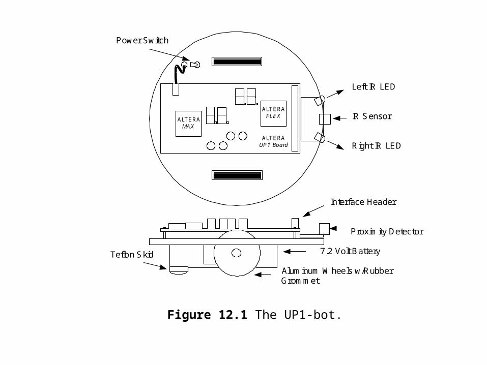
Left IR LED IR Sensor Right IR LED
ALTERA UP1 Board
Interface Header Proximity Detector 7.2 Volt Battery Aluminum Wheels w/Rubber Grommet
Teflon Skid
Power Switch
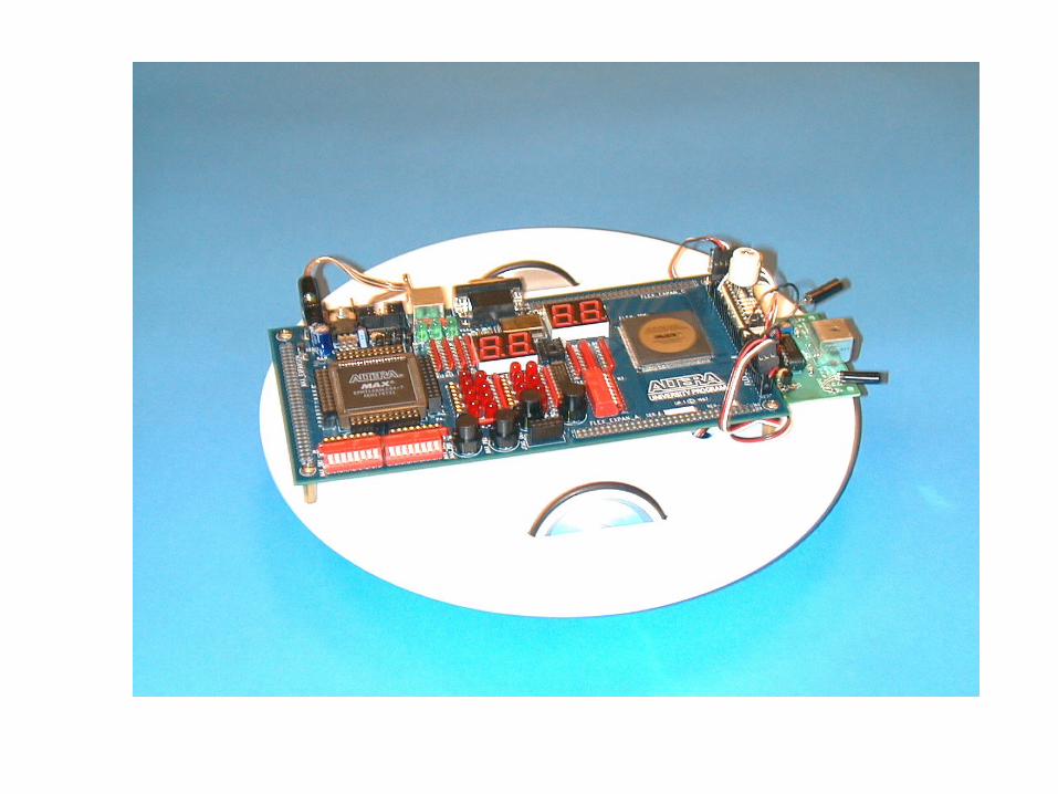
Figure 12.1 The UP1-bot.
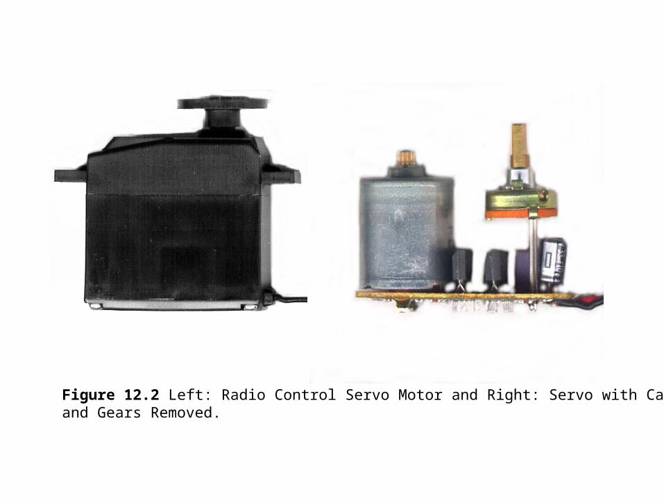
Figure 12.2 Left: Radio Control Servo Motor and Right: Servo with Case and Gears Removed.
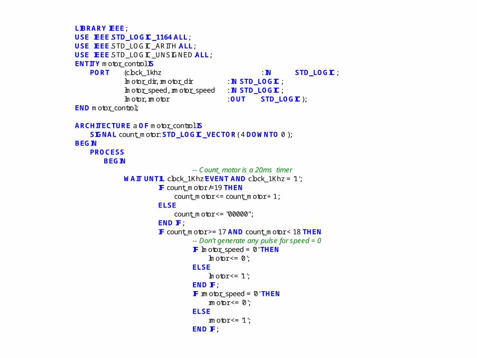
LIBRARY IEEE; USE IEEE.STD_LOGIC_1164.ALL; USE IEEE.STD_LOGIC_ARITH.ALL; USE IEEE.STD_LOGIC_UNSIGNED.ALL; ENTITY motor_control IS PORT (clock_1khz : IN STD_LOGIC; lmotor_dir, rmotor_dir : IN STD_LOGIC; lmotor_speed, rmotor_speed : IN STD_LOGIC; lmotor, rmotor : OUT STD_LOGIC); END motor_control; ARCHITECTURE a OF motor_control IS SIGNAL count_motor: STD_LOGIC_VECTOR( 4 DOWNTO 0 ); BEGIN PROCESS BEGIN -- Count_motor is a 20ms timer WAIT UNTIL clock_1Khz'EVENT AND clock_1Khz = '1'; IF count_motor /=19 THEN count_motor <= count_motor + 1; ELSE count_motor <= "00000"; END IF; IF count_motor >= 17 AND count_motor < 18 THEN -- Don’t generate any pulse for speed = 0 IF lmotor_speed = '0' THEN lmotor <= '0'; ELSE lmotor <= '1'; END IF; IF rmotor_speed = '0' THEN rmotor <= '0'; ELSE rmotor <= '1'; END IF;
-- Generate a 1 or 2ms pulse for each motor -- depending on direction -- reverse directions between the two motors because -- of servo mounting on the UP1-bot base ELSIF count_motor >=18 AND count_motor <19 THEN IF lmotor_speed /= '0' THEN CASE lmotor_dir IS -- FORWARD WHEN '0' => lmotor <= '1'; -- REVERSE WHEN '1' => lmotor <= '0'; WHEN OTHERS => NULL; END CASE; ELSE lmotor <= '0'; END IF; IF rmotor_speed /= '0' THEN CASE rmotor_dir IS -- FORWARD WHEN '1' => rmotor <= '1'; -- REVERSE WHEN '0' => rmotor <= '0'; WHEN OTHERS => NULL; END CASE; ELSE rmotor <= '0'; END IF; ELSE lmotor <= '0'; rmotor <= '0'; END IF; END PROCESS; END a;
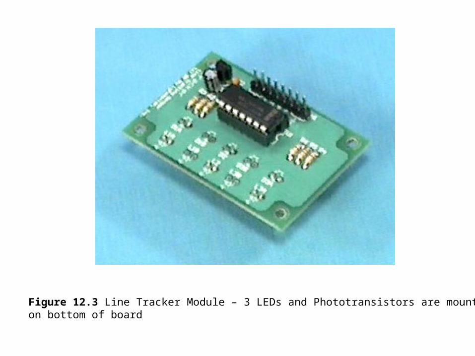
Figure 12.3 Line Tracker Module – 3 LEDs and Phototransistors are mounted on bottom of board
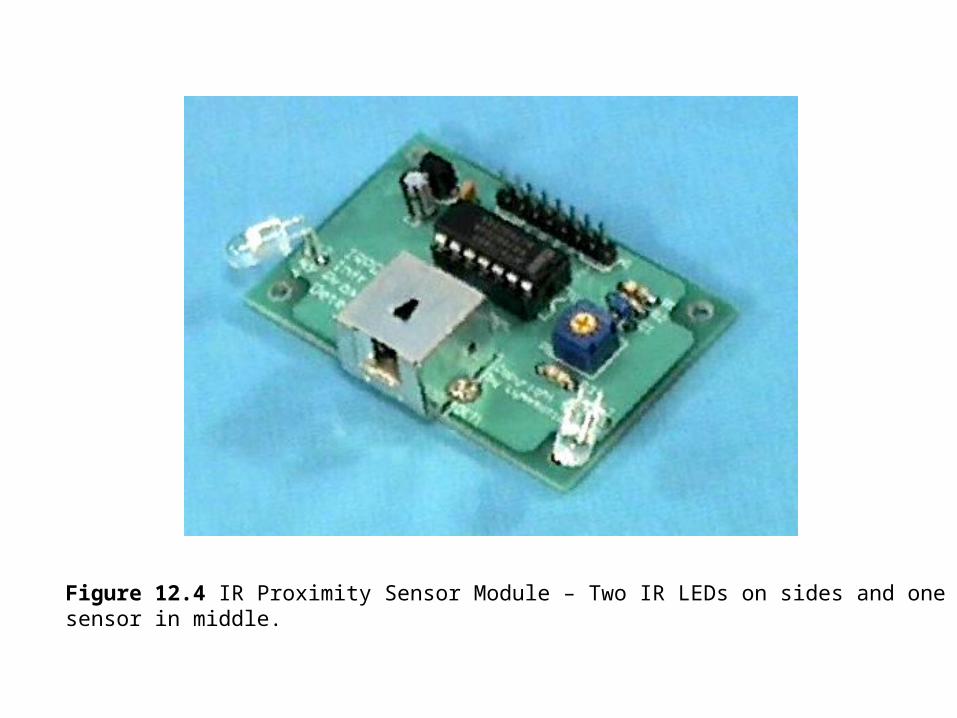
Figure 12.4 IR Proximity Sensor Module – Two IR LEDs on sides and one IR sensor in middle.
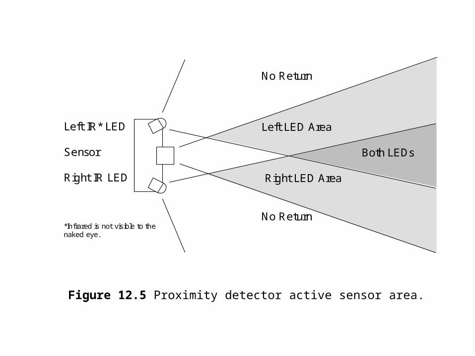
Left IR* LED Sensor Right IR LED *Infrared is not visible to the naked eye.
No Return Left LED Area Both LEDs Right LED Area No Return
Figure 12.5 Proximity detector active sensor area.
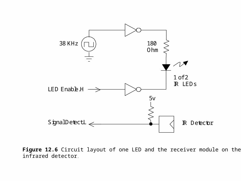
LED Enable.H Signal Detect.L
5v
38 KHz 180 Ohm
1 of 2 IR LEDs
IR Detector
Figure 12.6 Circuit layout of one LED and the receiver module on the infrared detector .
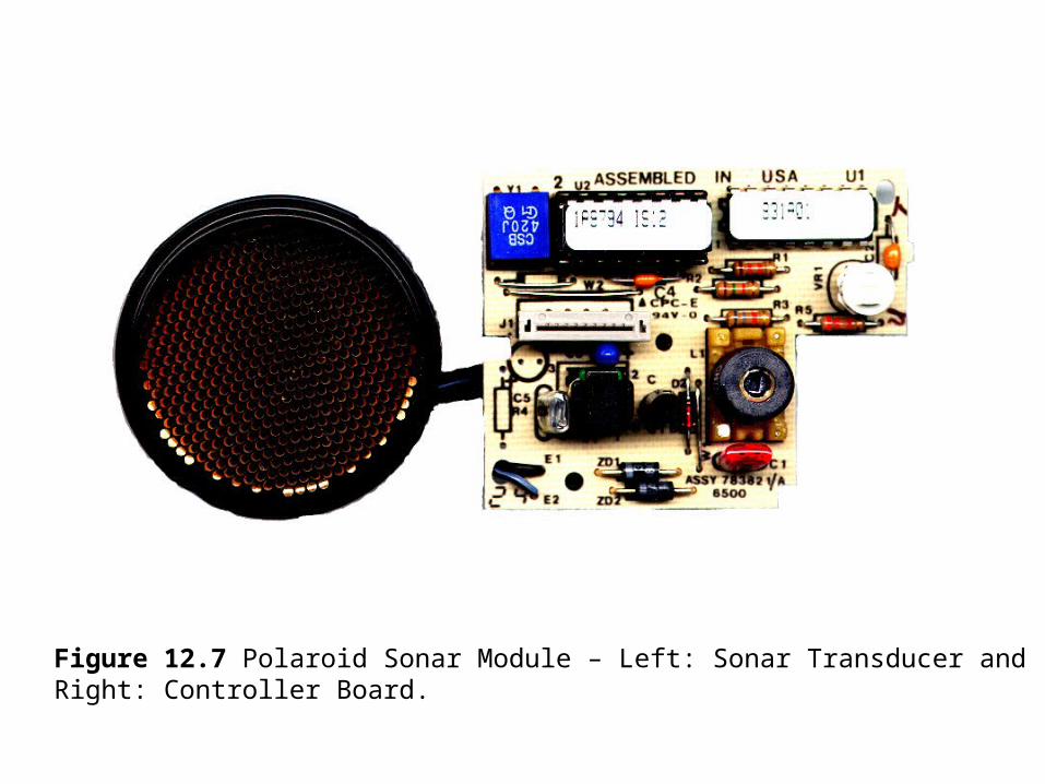
Figure 12.7 Polaroid Sonar Module – Left: Sonar Transducer and Right: Controller Board.
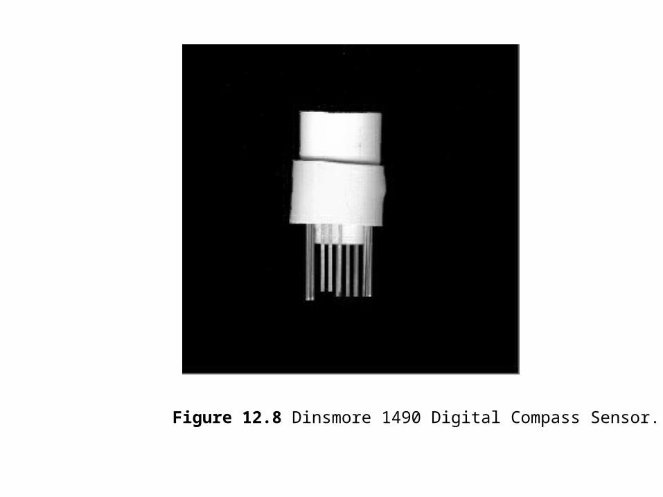
Figure 12.8 Dinsmore 1490 Digital Compass Sensor.
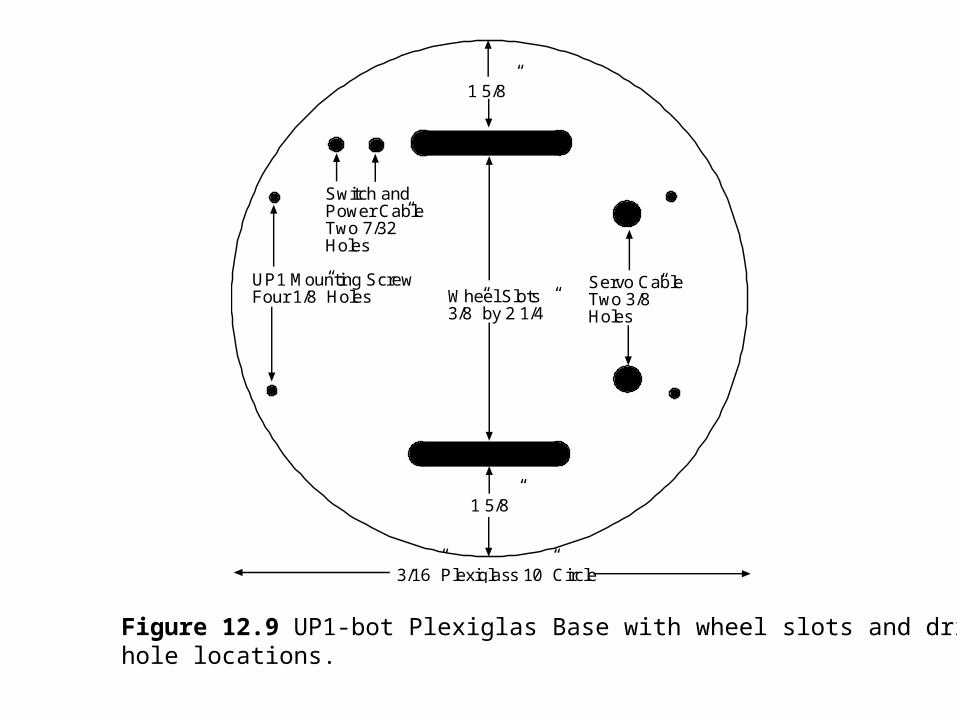
Wheel Slots3/8” by 2 1/4”
Servo CableTwo 3/8”Holes
UP1 Mounting ScrewFour 1/8” Holes
Switch andPower CableTwo 7/32”Holes
3/16” Plexiglass 10” Circle
1 5/8”
1 5/8”
Figure 12.9 UP1-bot Plexiglas Base with wheel slots and drill hole locations.
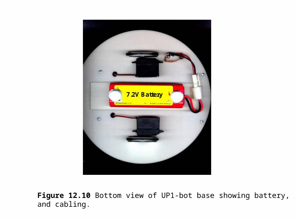
7.2V Battery
Figure 12.10 Bottom view of UP1-bot base showing battery, servos and cabling.
Figure 12.11 Top View of UP1-bot Base with Compass and IR Proximity Sensor Modules.

Table 12.1 UP1-bot FLEX Expansion B Header Pins
Header Pin FLEX Pin Header Pin FLEX Pin
1 Unregulated Power 2 GND
3 VCC 4 GND
5 VCC (Right Servo VCC) 6 GND (Right Servo VCC)
7 No connection 8 DI1/99
9 DI2/92 10 DI3/210
11 DI4/212 12 DEV_CLR/209
13 DEV_OE/213 14 DEV_CLK2/211
15 109 16 110 (Right Servo Signal)
17 111 18 113
19 114 20 115
21 116 22 117
23 118 24 119
25 120 26 126
27 127 28 128
29 129 30 131
31 132 32 133
33 134 34 136
35 137 36 138
37 139 38 141
39 142 40 143
41 144 42 146
43 147 44 148
45 149 46 151
47 152 48 153(IR Sensor Out)
49 154(IR Right LED) 50 156(Compass West)
51 157(IR Left LED) 52 158(Compass East)
53 159 54 161(Compass South)
55 162(Left Servo Signal) 56 163(Compass North)
57 VCC (Left Servo VCC) 58 GND (Left Servo GND)
59 VCC 60 GND
Note: Pins in parenthesis are used for UP1-bot Interfacing