figure 2.1 (a) torsional spring-mass system. (b) spring...
TRANSCRIPT

Ta
m
Ta
(a) (b)
va
Ts
vs
FIGURE 2.1
(a) Torsional spring-mass system. (b) Spring element.
Dorf/BishopModern Control Systems 9/E
© 2000 by Prentice Hall, Upper Saddle River, NJ.

y
by ky
kWallfriction, b
MassM
(a) (b)
r (t)Force
r (t)
yM
FIGURE 2.2
(a) Spring-mass-damper system. (b) Free-body diagram.
Dorf/BishopModern Control Systems 9/E
© 2000 by Prentice Hall, Upper Saddle River, NJ.

Voltagev (t)
0Time
e�a2t
2(p /b2)
FIGURE 2.4
Typical voltage response for underdamped RLC circuit.
Dorf/BishopModern Control Systems 9/E
© 2000 by Prentice Hall, Upper Saddle River, NJ.
(a) (b)
p
2
�p
p
T
up
2�
Length L
Mass M
u
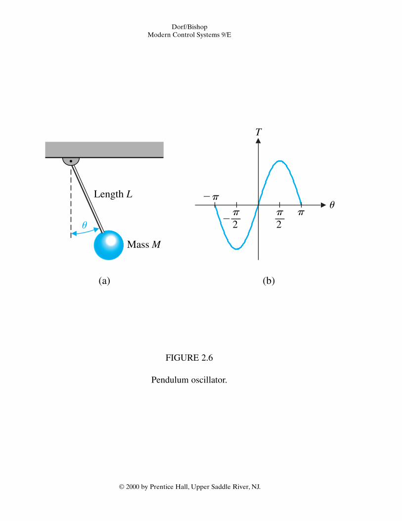
FIGURE 2.6
Pendulum oscillator.
Dorf/BishopModern Control Systems 9/E
© 2000 by Prentice Hall, Upper Saddle River, NJ.

jv
0
s1
s2
u � cos�1z
�2zvn �zvn
jvn�1 � z2
�jvn�1 � z2
vn
s
FIGURE 2.9
An s-plane plot of the poles and zeros of Y(s).
Dorf/BishopModern Control Systems 9/E
© 2000 by Prentice Hall, Upper Saddle River, NJ.

jvn
z increasing
z � 1z � 1
z � 1
z � 1
z � 0 jv
0s
vn
FIGURE 2.10
The locus of roots as z varies with vn constant.
Dorf/BishopModern Control Systems 9/E
© 2000 by Prentice Hall, Upper Saddle River, NJ.

�
Armature
Rf
Ra
Vf
La
Lf
iaia
if (t)Field
v, uInertia � JFriction � b
Load
Statorwinding
Rotor windings
Brush
Bearings
Shaft
BrushCommutator
Inertiaload
Angleu
(a) (b)
�
N
S
FIGURE 2.17
A dc motor (a) wiring diagram and (b) sketch.
Dorf/BishopModern Control Systems 9/E
© 2000 by Prentice Hall, Upper Saddle River, NJ.

FIGURE 2.18
A pancake dc motor with a flat-wound armature and a permanentmagnet rotor. These motors are capable of providing high torquewith a low rotor inertia. A typical mechanical time constant is in
the range of 15 ms. (Courtesy of Mavilor Motors.)
Dorf/BishopModern Control Systems 9/E
© 2000 by Prentice Hall, Upper Saddle River, NJ.

�
�
Tm(s)If (s)Vf (s) s
11
R f � L f s
DisturbanceTd (s)
TL(s)Speedv (s) Position
u (s)Output
Field
1
Js � b
Load
Km
FIGURE 2.19
Block diagram model of field-controlled dc motor.
Dorf/BishopModern Control Systems 9/E
© 2000 by Prentice Hall, Upper Saddle River, NJ.

�
�
Tm(s)Va(s)
Js � b1
s1Km
Ra � Las
Kb
�
�
DisturbanceTd (s)
TL(s)
Speedv (s) Position
u (s)
Back emf
Armature
FIGURE 2.20
Armature-controlled dc motor.
Dorf/BishopModern Control Systems 9/E
© 2000 by Prentice Hall, Upper Saddle River, NJ.

Va(s)
Ra
La
Ia
If
u, v J, bVb
�
�
�
�
Table 2.5
Transfer Functions of Dynamic Elements and Networks6. dc motor, armature-controlled, rotational actuator
Dorf/BishopModern Control Systems 9/E
© 2000 by Prentice Hall, Upper Saddle River, NJ.

V2(s)
Shaft
u (s), v (s)�
�
Dorf/BishopModern Control Systems 9/E
© 2000 by Prentice Hall, Upper Saddle River, NJ.
Table 2.5
Transfer Functions of Dynamic Elements and Networks13. Tachometer, velocity sensor

Vf (s)Output
u (s)Km
s(Js� b)(Lf s� Rf)G(s) �
FIGURE 2.22
Block diagram of dc motor.
Dorf/BishopModern Control Systems 9/E
© 2000 by Prentice Hall, Upper Saddle River, NJ.

Y1(s)
Y2(s)
R1(s)
R2(s)System
Inputs Outputs
FIGURE 2.23
General block representation of two-input, two-output system.
Dorf/BishopModern Control Systems 9/E
© 2000 by Prentice Hall, Upper Saddle River, NJ.

Y1(s)R1(s) G11(s)�
�
G 12(s)
G21 (s)
Y2(s)R2(s) G22(s)�
�
FIGURE 2.24
Block diagram of interconnected system.
Dorf/BishopModern Control Systems 9/E
© 2000 by Prentice Hall, Upper Saddle River, NJ.

Ta
m
Ta
(a) (b)
va
Ts
vs
FIGURE 2.1
(a) Torsional spring-mass system. (b) Spring element.
Dorf/BishopModern Control Systems 9/E
© 2000 by Prentice Hall, Upper Saddle River, NJ.

y
by ky
kWallfriction, b
MassM
(a) (b)
r (t)Force
r (t)
yM
FIGURE 2.2
(a) Spring-mass-damper system. (b) Free-body diagram.
Dorf/BishopModern Control Systems 9/E
© 2000 by Prentice Hall, Upper Saddle River, NJ.

Voltagev (t)
0Time
e�a2t
2(p /b2)
FIGURE 2.4
Typical voltage response for underdamped RLC circuit.
Dorf/BishopModern Control Systems 9/E
© 2000 by Prentice Hall, Upper Saddle River, NJ.

MassM
Nonlinearspring
f � y2
Springforce
Equilibrium(operating point)
f0
f
dfdy y � y0
�
(a) (b)
y0
y
y
FIGURE 2.5
(a) A mass sitting on a nonlinear spring. (b) The spring force versus y.
Dorf/BishopModern Control Systems 9/E
© 2000 by Prentice Hall, Upper Saddle River, NJ.

(a) (b)
p
2
�p
p
T
up
2�
Length L
Mass M
u
FIGURE 2.6
Pendulum oscillator.
Dorf/BishopModern Control Systems 9/E
© 2000 by Prentice Hall, Upper Saddle River, NJ.

�3 �2 �1 0s
� pole� zero
jv
FIGURE 2.7
An s-plane pole and zero plot.
Dorf/BishopModern Control Systems 9/E
© 2000 by Prentice Hall, Upper Saddle River, NJ.

jv
0
s1
s2
u � cos�1z
�2zvn �zvn
jvn�1 � z2
�jvn�1 � z2
vn
s
FIGURE 2.9
An s-plane plot of the poles and zeros of Y(s).
Dorf/BishopModern Control Systems 9/E
© 2000 by Prentice Hall, Upper Saddle River, NJ.

jvn
z increasing
z � 1z � 1
z � 1
z � 1
z � 0 jv
0s
vn
FIGURE 2.10
The locus of roots as z varies with vn constant.
Dorf/BishopModern Control Systems 9/E
© 2000 by Prentice Hall, Upper Saddle River, NJ.

y(t)
e�zvnt envelope
y0Overdamped case
Underdamped case
Time0
FIGURE 2.12
Response of the spring-mass-damper system.
Dorf/BishopModern Control Systems 9/E
© 2000 by Prentice Hall, Upper Saddle River, NJ.

(a) (b)
Currentr(t)
v1(t) v2(t)R1
C1 R2 C2 L
Friction b2
Friction b1
k
Velocityv2(t)
Velocityv1(t)
Force r(t)
M2
M1
FIGURE 2.16
(a) Two-mass mechanical system. (b) Two-node electric circuitanalog C1 = M1, C2 = M2, L = 1/k, R1 = 1/b1, R2 = 1/b2.
Dorf/BishopModern Control Systems 9/E
© 2000 by Prentice Hall, Upper Saddle River, NJ.

�
Armature
Rf
Ra
Vf
La
Lf
iaia
if (t)Field
v, uInertia � JFriction � b
Load
Statorwinding
Rotor windings
Brush
Bearings
Shaft
BrushCommutator
Inertiaload
Angleu
(a) (b)
�
N
S
FIGURE 2.17
A dc motor (a) wiring diagram and (b) sketch.
Dorf/BishopModern Control Systems 9/E
© 2000 by Prentice Hall, Upper Saddle River, NJ.

FIGURE 2.18
A pancake dc motor with a flat-wound armature and a permanentmagnet rotor. These motors are capable of providing high torquewith a low rotor inertia. A typical mechanical time constant is in
the range of 15 ms. (Courtesy of Mavilor Motors.)
Dorf/BishopModern Control Systems 9/E
© 2000 by Prentice Hall, Upper Saddle River, NJ.

�
�
Tm(s)If (s)Vf (s) s
11
R f � L f s
DisturbanceTd (s)
TL(s)Speedv (s) Position
u (s)Output
Field
1
Js � b
Load
Km
FIGURE 2.19
Block diagram model of field-controlled dc motor.
Dorf/BishopModern Control Systems 9/E
© 2000 by Prentice Hall, Upper Saddle River, NJ.

�
�
Tm(s)Va(s)
Js � b1
s1Km
Ra � Las
Kb
�
�
DisturbanceTd (s)
TL(s)
Speedv (s) Position
u (s)
Back emf
Armature
FIGURE 2.20
Armature-controlled dc motor.
Dorf/BishopModern Control Systems 9/E
© 2000 by Prentice Hall, Upper Saddle River, NJ.

Vf (s)
Rf
Lf
Ia
If u, v
J, b
�
�
Table 2.5
Transfer Functions of Dynamic Elements and Networks5. dc motor, field-controlled, rotational actuator
Dorf/BishopModern Control Systems 9/E
© 2000 by Prentice Hall, Upper Saddle River, NJ.

Va(s)
Ra
La
Ia
If
u, v J, bVb
�
�
�
�
Table 2.5
Transfer Functions of Dynamic Elements and Networks6. dc motor, armature-controlled, rotational actuator
Dorf/BishopModern Control Systems 9/E
© 2000 by Prentice Hall, Upper Saddle River, NJ.

V2(s)
Shaft
u (s), v (s)�
�
Dorf/BishopModern Control Systems 9/E
© 2000 by Prentice Hall, Upper Saddle River, NJ.
Table 2.5
Transfer Functions of Dynamic Elements and Networks13. Tachometer, velocity sensor

Vf (s)Output
u (s)Km
s(Js� b)(Lf s� Rf)G(s) �
FIGURE 2.22
Block diagram of dc motor.
Dorf/BishopModern Control Systems 9/E
© 2000 by Prentice Hall, Upper Saddle River, NJ.