file god ad no0. 5 s d t ic us bateriwl … · d t ic us bateriwl army"command w1 s ielecteb...
TRANSCRIPT

AD NO0. FILE_____GOD_
REPORT NO. USACSTA-6572 li 5
US ARMY"D T IC bATERIWL COMMAND
W1 S IELECTEB
SEP 0 4 W7o
SPECIAL STUDY
OF
GUIDE FOR THE DEVELOP•MENT OF
SAFETY ASSESSMENT REPORT (SAR)
MARTIN MOSSA
SAFETY OFFICE
U.S. ARMY COMBAT SYSTLMS TEST ACTIVITYABERDEEN PROVING GROUND, Yn 21005-5059
AUGUST 1987
DISnRflVUTc1nN STAT1EMILN'T AApproved for public reloosel
Distribution Unlimited
Prepared for:U.S. ARMY MATERIEL COM1ANDALEXANDRIA, VA 22333-0001 DISTRTBUTION UNLIMITED.
87 9 ( 087

DISPOSIT.ION INSTRUCTIONS
Destroy this report when no longer needed. Do not return to theoriginator.
DISCLAIMER STATEMENT
The -laws, opinions, and/or findings in this report are those ofthe author(s) ana shoald not be construed as an official Departmentof the Army position, unless so designated by other Officialdocumentation.

Unc lassaified
SECURITY CL455IFKATION OF THIS PAGE _______________
REPORT DOCUMENTATION PAGE Im OMNo.0 "18____ ___ ___ ___ ___ ___ ___ ___ ___ ___ ___ ___ _ IExrp. Datie: Jun 30,1l06
I&. REPORT SECURITY CLASSIFICATION lb. RESTRICTIVE MARKINGSUnclassified
2a. SECURITY CLASSIFICATION AUTHORITY 3. DISTRIBUTION /AVAILABILITY OF REPORT
2b. DECLASSIFICATION / DOWNGRADING SCHEDULE Distribution Unlimited.None
S
4. PERFORMINGV~GMkNIZATION REPORT NUMBER(S) S. MONITORING ORGANIZATION REPORT NUMBER(S)
USACSA-72 Not applicable
S6a. NAME OF PERF~ORMING ORGANIZATION (4 OFFICE SYMBOL 7a. NAME OF MONITORING ORGANIZATIONU.S. Army Combat Systums (if applicable) Not applicableTest Activity STECS-SO-S
k E. ADDRESS (City, State, and ZIP Code) 7b. ADDRESS (City State, and ZIP Code)
Aberdeen Proving Ground, MD .21005-5059 Not applicable
Ba. NAME OF FUNDING i SPONSORING B b. OFFICE SYMBOL 9. PROCUREMENT INSTRUMENT IDSNTIFICATION NUMBERORGANIZATION 0 apif kb) o applicable)
Sc. ADDRESS (City. State, and ZIP Code) 10. SOURCE OF FUNDING NUMBERSPROGRAM PROJECT TASK WOr'K UNITELEMENT NO, INO. NO. ACCESSION NO.
11. TITLE (Include Secur'ity ClaSSification,)GUIDE FOR THE DEVELOPMENT OF SAFETY ASSESSMENT REPORT (SAR)
12. PERSONAL AUTHOR(S)Mossa, Martin-
13.TYPE OF REPORT 13.TIME COVERED TO u 11 4. DATE OF REPORT (Year, Month, Day) 1'5. PAGE COUNT
16 UPPLEMENTARY NOTATIONThis report in, a product of the U.S. Army Materiel Command Action Committee for SystemSafety.
F1E. GROUP CODSUGRU 1 SafJECTy AsERSsmeontinReponrersit (S eAR) Sn dniyse SaeyblcnuerCILD GOUAPCDE SUBJECTU TERMSy (CsssmntinReponrtvs ifR neS ysaem Snade fy etyblcnmbr
Preliminary Hazard Analysis
I I IFault Tree Analysis19. ABSTRACT (Continue on reverse if necessary and identify by blor.' number)
This report was developed by the Research and Development (R&D) subcommittee of the AMCAction committee for system safety and is intended to provide researchers, combatdevelopers, program managers, contractors, testers and users guidance to develop acomprehensive and effective safety assessment report (SAR).
20. DISTRIBUTION /AVAILABILITY OF ABSTRACT 21 ABSTRACT SECURITY CLASSIFICATIONOUNCLASSIrIED/UNLIMITED 0 SAME AS RPT. CDTIC USERS Unclassified
22a. NAME OF RESPONSIBLE INDIVIDUAL 22b TELEPHONE (include Area Cd)2c FIESMOMartin Mossa 301-278-3898
00FR¶473, 84 MAR 83 APR edition may be used unil exhausted- SECURITY CLASSIFICATION OF THIS PAGEDDFRMAll other editions are obsolete. Unclassified

AMC ACTION COMDIITTEE FOR SYSTEM SAFETY
Research and DevelopmentSub-comittee
Martin Mossa USACSTA
Doug Paul USABRDC
Charles Garrett USACPDZC
Felix Aguinaga USAAMICOM
Jim Stanley PM-ThDE
Accesio~i For
NTIS CRA&ID'OiC 1A0 UU:,a'I !- o r,-r.• F[]f 1
Ju.,iic•io l.... ... ............ ..........
By ....................... ......
Di ':t ib ityioe I
A,;!i~abiiity Codes
Dist SpdIt ora
bloeINSia OEapy r

TABLE OF CONTENTS
PAGE
III SAFETY ASSESSMENT REPORT FORMAT GUIDE . . . . . . . . . . . . . 1
AV muuczso* ** * o * * . * . * 0 0 . * 0 . . * . 0 . A-i
C SYSTEM SAFETY ANALYSIS (EXAMPLE) . . . ... . . ... .. . . C-i
I DISTRIBUTION LIST . . . . . . . . . . . . . . . . . . . . . . . . E

GUIDE FOR THE DEVELOPMENT OFSAFETY ASSESSMENT REPORT (BAR)
'.1. INTRODUCTION:
>•This report was developed by the R&D subcommittee of the AMC actioncomittee for system safety and is intended to provide researcher. combatdevelopers, program managers, contractors, testers, and sere*, guidance todevelop a comprehensive and effective safety assessment report (MAR). The SARis a formal, comprehensive safety report that simarises the safety data thathas been collected and evaluated during the life cycle of an item (ref 1). Itexpressec, the considered judgement of the contractor or developing agencyregarding the hazard potential of the item and any actions or precautions thatare recommended to minimize these hazards and to reduce the exposure ofpersonnel and equipment to them.
II. RESPONSIBILITIES:
a. Materiel Commanders: AR 385-16 (ref 2) requires tLat an SAR will beprovided to the combat developer and the operational tester, development testagency, and other testing agencies ^t least 60 days before the start of theirrespective tests.
b. Heads of operational test (OT) and development test (DT) andevaluation agencies, activities and commands:
1. Use the SAR information to integrate safety into test planning and
procedures and for shipping and handling of the system.
2. Ensure that developmental testing will not begin until an SAR has beenreceived, reviewed, and accepted by the test agency.
11. SAFETY ASSESSMENT REPORT FOR FORMAT CULIJE:
The SAR is a formal summary of the safety data, collected during theiesigu and development of the system, which provides a comprehensive evaluationof safety risks being assumed prior to test or operation of a system or atcontract completion. In it, the contractor or material developer summarizesthe hazard potential of the item, provides a risk assessment and recommends
procedures or other corrective actions to reduce these hazards to an acceptablelevel.
1. INTRODUCTION:
STATE THE PURPOSE OF THE SAFETY ASSESSMENT REPORT.
The purpose of the SAR is to provide a comprehensive evaluation of thesafety risks being assumed prior to test or operation of the system or atcontract completion. It should identify all safety features of the hardwareand system design and procedural hazards that may be present in the systembeing acquired. It should include, specific procedural controls andprecautions that should be followed.
1

I2. S. R.5 I. iD. Develop by reference other program specifications suchas technical manuals, system safety program plans, spezifications, etc., asapplicable and:
a. State purpose and intended use of item.
The description of the system should begin with its intended use and theaisaiom that it is required to accomplish.
b. Give background information on development of item. IProvide an historical summary of the system's development.
c. Describe the item fully.
Include name, type, model number, presence of any radioactive source,general physical features including size. weight, payload, and specificoperatiomal features. Describe major subsystem@ and components.
d. Describe fully and system that will be tested along with the item.
For example, a weapons system may need to be tested while mounted on aspecific vehicle. While the vehicle may already be a fielded item, itsinterface with the weapons system needs to be evaluated.
e. Provide photos, charts, flow diagrams, or schematics to support thesystem description, test or operation. I3. SY7ZK 0PFATIONS:
a. Present a complete sequence of system operations and emphasize thesafety features.
A system is designed, manufactured, and maintained to accomplish aspecific mission. It has certain characteristics and limitations within which
it will function properly. Procedures which should be followed in sequence forsafe operation should be spelled out so that important steps are not by-passed.Hazardous operations should be conducted only in designated areas. Onlyessential personnel should be permitted within the hazard area during aspecific operation. Personnel and organizations should be notified before the Ioperation is begun. Escape routes should be clearly designated.
b. List and describe fully any special procedures needed to assure safeoperatinns, including emergency procedures.
For example, misfire/hangfire/cook-off procedures or warnings should beemphasized for all weapons, as well as load/stow/reload procedures for thesmoke grenade and associated launchers.
c. Describe operating environments and specific skills for safeoperation, maintenance, or disposal.
2

4. Describe special facility requirements or personal equipment tosupport/operate the system.
For exampl*, fire suppression system, climate cont, ol, ventilation, ear oreye protection, gloves, clothing, etc.
4. SAWlr! ENCINyU!C:
a. Include all system saiety data and include contractor safety datadeveloped during design and development phases.
The system safety engineering process may begin with known previousexperience and knowledge. The lessons learned from previous systemdevelopments should be made available for ths hazard analysis. Other dataavailable from common resource banks such as government defense and industryshould be considered. Accident and incident data should be surveyed for commontypes of safety hazards.
As long as hazards exist, there is the possibility, no matter howimprobable, that an accident will occur. Accidents are possible when thesystem or its components are being tested during deielopment. However, testsare usually carried out by highly trained personnel who are alert to thepossibility that failures at that stage are likely. But vnen the systembecomes operational, the operational personnel may be less Ailled,knovledgeable, or capable of meeting emergencies. Designers must thereforeassume that in the hands of the ultimate user, the probability of accidents isgreater.
b. Show analyses and tests performed to point out hazardous conditions inthe item.
Hazard analyses are the heart of the system safety evaluation. The typesof analyses that vere performed must be stated in this section and the purpose
must be clearly defined. Since there are many types of hazard analyses, aspecific attempt to understand the system and the need to perform unique typesof analyses should be made.
An explanation and instru% tions on the development of hazard analyses areincluded in Appendix C of this report. They %nclude preliminary hazardanalysis (PRA), subsystem hazard analysis (SSRA), and fault tzeeanalysis (FTA).
(1) Show hazard severity and the effect of hazards on system operationand mission.
Hazard severity and probability of occurrence should be categorized inaccordance vith procedures in paragraphs 4.5.1 and 4.5.2 of MIL-STD-882B. Areproduction of these tables are included in Appendix C of this report.
(2) Explain uystem interfaces and associated safety implications.
The human/machine/hazards need to be examined and all of the system's
interfaces should be pointed out. Understanding the need for a complete
3

evaluation of hazards to assure that controls are considered in the PEA, i,vital. System definition will initialy result in a suitable general design.it is understood that all haaards may not be recognized at this time. However,this analysis should be continuously upgraded as the development phaseprogresses. Catastrophic hazards should be considered as a source of faulttree analysis so that the events leading to ta', undesired event can be traced.
(3) Show the results of hazard analysis validation tests.
The method by which safety controls are brought into existence must bestated in a clear, positive policy. It will be necessary to verify that theparticular design meets the safety requirements specified. A safety testmatrix which identifies the particular ireas that were tested, along with theresults and actions to abate the hazards should be present.
c. Include surface danger none data and other range safety data forweapons or explosive items and sources of nonionizing/ionizing radiation.
This section encompasses a wide variety of possible safety hazards whichmay or may not be an integral part of the system. If the system relates to anyof the above, the information must be included. The following data needs to beconsidered:
(1) General range control precautions, instructions, and danger zonesnecessary in the firing and other use of ammunition and explosives in all typesof test operations utilizing water, airspace, and assigned land areas.
(2) Lasers are an example of nonionizing Tadiation. Three aspects oflaser application which influence the total hazard evaluation are the lasersystem capability of injuring personnel, the en-ironment in which the laser isused, and the personnel who operate the laser and the personnel who may beexposed.
(3) Any ionizing radiation hazards that may be present within the systemor as the result oF operating or maintaining the system, must be identified.Methods of safe guards need to be communicated.
d. When the developer states that the test presents no hazard, includethe basis for this decision and supporting evidence.
In most cases some form of hazard analysis should be performed beforedetermining -.hat no hazards exist. It is not enough to compare the dystem inquestion to some other system that was previously fielded. Copies of allanalyses and test reports should be included as evidence.
e. Health hazards (per AM4C Suppl I to AR 385-16)
(1) Addres- any known or potential health hazards to test participants asa result of the design or use of the system.
(2) Include results (attach if available) of mndatory health hazardsstudies made by medical agencies (AR 40-10). Also includp results of medicalresearch or consultations made to clarify the nature and degree of the hazardto user personnel.
4

kImples would include tests for toxic gas concentrations, noise levels(including impulse as veil as steady state), and radiation measurements.
c. Indicate whether the restrictions for human use volunteers (AR 70-35)apply.
5. (NLUR 1N1 AND RRCOI4UDATIONR:
a. State whether the system is completely safe for testing or whether itis safe for testing with exception@.
It should be remembered that test personnel, both during developmenttestiug and operational testing, must operate, fire, evaluate, etc., themateriel to be tested and it is necessary for their sefety and the safety ofmilitary personnel who will later use the systems, that they understand all ofthe peculiarities of the system. It is in this section that all known orsuspected hazards need to be summarized along with safe Suards needed toprotect users against serious injury or loss of the system.
b. List exceptions for all real and potential hazards that may beencountered. Make specific safety recomendations to ens,,re the safety ofpersonnel and preservation of materiel and property.
(1) Related hazards should be classed as expected to occur under normalor abnormal operating conditions.
(2) Explosive, electrical, mechanical, hclth, radiological, andcompooite hazards should be covered.
u. Highlight any known safety or health problems that will requirefurther investigation during testing.
6. ]J•C.
List references such as test reports, preliminary operating manual.s,maintenance manuals, and health hazard studies.
7. SIGNATURE BLOCKS:
The SAR should be signed as stated below:
Prepared by: _Date__
Concurred by: loate_
Approved by: Date_
(Page 6 Blank)
il'- IPt, A

IT ADICDIX
APPENDIX A - REFERENCES
I. D& Pamphlet 385-16 (draft), System Safeity Mavagemuent Guide, 1 January 1986.
2. All 385-16, System Safety Engineering and Management, 3 Septermber 1985.
3. MIM-STD-882B, System Safety Program Itoquirernents, 30 March 1984.I
A-i(Page A-2 Blank~)

|I
APPENDIX 3 - SAFETY ASSESSMENT REPORT (DI-SAFT-80102)
1. Introduction. Ia. State purpose of the safety assessment report.
b. Give short sumary.
e. Provide an operational scenario description and ava'iysis of hazards
jeceliar to the operational environment.
2. System description.
a. State purpose and intended use of item.
b. Give backgroun4 information on development of item.
c. Describe the item fully, include name, type, model number, presence ofany radioactive source, general physical features, and specific. operationalfeatures.
d. Describe fully any system that will be tested along with the item.
3. System operations.
a. Present a coplete sequence of system operations. Emphasize the safetyfeatures.
b. Lest and describe fully and special procedures needed to assure safeoperations.
4. Safety engineering.
a. Include all system safety date and include contractor safety datadeveloped during design and developmer"t phases.
b. Show analyses and tests performed to point out hazardous conditions inthe item.
(1) Show hazard sever-ty and probability of occurrence (MIL STD 882), ifapplicable, and the effect of hazards on system operation and mission.
(2) Explain system interface and associated safety implications.
(3) Show results of hazard analysis validation tests.
c. Include surface danger zone data and other range safety data forveapoz~ or explosive items and sources of nonionizing/ionizing radiation.
d. When the developer states that the teat presents no hazard, include thebasis for this decision and the supporting evidence.
B-1
e. Address any known or potential health hazards to test participants as aresult of the design or use of the system. AttaOh OTSG Health HazardAssesment (AR 40-10).
5. Conclusions and -ecommendations.
a. State whethvr the system is completely safe for testing or whether itis safe for testing with exceptions.
b. List- exceptions Cor all real and potential hazards that may beencountered. Make specific safety recomendations to insure the safety ofpersonnel and preservation of materiel and property.
(1) Related hazards should be classed as expected to occur under normal orabnormal operating conditions.
(2) Explosive, electrical, mechanical, health, radiological, andcomposite-type hazards should also be covercd.
c. Highlight any known safety or health problems that will require furtherinvestigation during testing.
6. References. List references such as test reports, preliminary opera'ing
manuals, maintenance mantials, and health hazard studies.
Prepared by: Date_ _ _ _ _
Concurred in by: Date_
Approved by: _Date
B-2

APPEIDIX C - SYSTEM SAFETY ANALYSIS
Starting in basic research (6.1) the developer and contractor should:perform various factory, laboratory, and proving ground tests of partd,compowants, and subsystems, using "breadboard" or "brassboard" configuration.
lrem the begining, the system shall be designed, in a timely and costeffective manner, to eliminate al.l potential ard actual safety and healthhazards. These hazards shall be identified and evaluated in accordance withhazards evaluatioc techniques as spelled out in NIL-STD-882B. These techniquesshall iaclude, but not be limited to the folloving:
I1
C-1

Preliminary Hazard Analysis (PHA
A Preliminary Hazard Analysis is an inductive process whichshould be conducted early In the design phase of the system lifecycle to identify in broad or gross terms the potential hazardsassociated with the postulated operational concept. Tha analysisIs a comprehensive, qualitative, evaluation of the system whichconsiders the system from the viewpoint of its operationalenvi.zt,.ient. As potentially hazardous operations, materials, anddesign are Identified, this information should be used in thedevelopmont of safety criteria to be imposed in theperformance/design specifications. The Preliminary Hazard
alysis, therefore, becomes a necessary system safety programelement to provide assurance that the system safety requirementsbecorw an integral part of the overall technical design
lequl rements.
The Preliminary Hazard Analysis should include, but not be
limited to, the following activities:
0 A review of pertinent historical safety experience data.
0 A categorized listing of basic hazard scurces including aridentification of possible causes in each category.
* An investigation of the various sources to determine theprovisions which have been developed for their control.
* Identificution of hazards sources for which Inadequatecontrol has been provided in the proposed design/procedures.
0 The provision of specific safety requirements/criteria whicheshould be incorporated into the program documentation toassure control of the sources which present unacceptablehazard levels.
The following activities, areas, conditions should be consideredwhen performing the PHA.:
1) Hazardous components
6 Hazardous materials0 Energy sourcesI FluIds and oils* Off-property sources* Pressure systems
2) Safety related interface considerations among variouselements
* EMI* Inadvertent activatione Fire/explosive initiation and propagation
c-2

3) Environmental constraints
1 Temperature extreMes1 Shock* Noise and health hazards0 X-Rays "
4) Construction constraints
In ad-4ition to many of the environmantal constraints are
* TransportationO Installation* Utilities* OSHA* Laser radiation
s) Operating, test and maintenance procedures
* Layout and lighting0 Crash safety* Egress and rescue
6) Facilities, support equipment and training
* Codes and standards0 Certification* Storage, assemb ly and checkout
7) Safety related equipment, safeguards
* Interlocks* Redundancy0 Fail safe design0 Fire suppression systems* Personnel protective equipment
C-3

PRELIMINARY HAZARD ANALYSIS (PHA) -
Imstructions for Comoletina
In Contract No. , enter the contract number for which PHA isI~ng performed.
Is Contractor enter the ame of the Cbntractorresponsible for the PHA.
In PHA Nc. , enter the FHA Number whic, shall be coded andsequentially numered by each Contractor for each- system. This codingsequence will be utilized for all related analysis.
In Revision No. , enter the revisitn number to indicate thelatest status.
In Subsystem , enter the nomenclature of the subsystemas broken out from the system.
In System enter the nomenclaturer of the applicablesystem.
In Drawing No. , enter the drawing number of the drawing on whichthe subsystem is Indicated.
In Prepared by . Date , the preparer will signand enter the date of Issue or completion on each sheet of the analysis.
In Reviewed by Date , the reviewer will signand enter the date of review on each sheet of the analysis.
In Approved by Date the Contractorx ProjectManager will sign to approve and enter the datreof approval on etch sheetof P-4lysis.
In (1) Function Description & No., enter the reference number and a brieffunctional description of the subsystem under analysis.
In (2) System Mode, enter the state of the system, at the time of thefailure mode or condition.
In (3) Hazard Description, enter the nature of hazard conditionintroduced by the failure of the subsystem.
In (4) Potential Cause, enter the most likely primary and secondarycauses of the hazard condition.
In (5) Effect on Subsystem/Interfacing Subsystems, enter a briefdescription of the hazard condition effect(s) on the subsystem and otherinterfacing subsystems.
C-4

PRELIMINARY HAZARD ANALYSIS (PHA) (cont'd)
Instructions for Completing
In (6) HSzard Category, enter the h;]hest applicable hazard class inaccordance with MIL-STD.i8ZB.
In (7) Redesign/Control Remarks, enter a brief description of theredesign/control/corrective action(s) necessary for the hazard conditionbeing analyzed. Enter name(s) cf related analysis and reference number(s)and which approach is being proposed - Design Change, Procedures, SpecialTraining, etc.
C-5

3 r (
U 19
II
•h i l
-A
K c-6
----------------------

SYSTEM HAZARD AKALYSIS (SHA)
Instructions for comleting
In Contract No. , enter the contract number for which SHA is beingperformed.
In Contractor __, enter the ram of the Contractor responsiblefor the SHA.
In SMA No. , enter the SHA number which shall be coded andsequentially numbered Iby each Contractor for each system. This codingsequence will be utilized for all related predictions and analysis.In Revision No. , enter the revision number to indicate thelatest status.
In System , enter the nomenclature of the applicable system.
In Drawing No. , enter the drawing number of the drawing on whichthe subfunction Is Indicated.
In Interfacing System enter the nomenclature of theapplicable interfacing system.
In Prepared by Date , the preparer will sign andenter the date of issue or completion on each sheet of the analysis.
In Reviewed by __Date , the reviewer will sitn and enterVh date of issue or completion on each sheet of the analysis.
In Approved by Date the Contractor's ProjectM.9nerr will sign to approve and enter TWe"Tae of approval on each sheetof analysis.
In (1) Hazard Description, -enter the nature of hazard conditionintroduced by the failure of the system.
In (2) System Node, enter the state of the system, instance before thefailure mode or condition.
In (3) Potential Cause, enter the most likely primary and secondarycauses of the hazard condition.
In (4) Effect(s) on System, enter a brief description of the, hazardcondition effect(s) on the system.
In (5) Effect(s) on Interfacing System(s), enter a brief description of,the hazard conditioo effect(s) on the interfacing system(s).
C-8

SYSTEM NAVA ANALYSIS (SKA) (cont d)
Instructions for cwoelt1na
In (6) Interfacing Parameters, enter the parameters responsible for theinterfaction of the system with other systems.
In (7) Hazard Category, enter the highest applicable hazard class inaccordance with NIL-ST•1S62S.
In (8) Rtedesign/Control Actions, enter a brief description of theredesign/control/corrective action(s) necessary for the hazard conditionbeing analyzed. Enter name(s) of related analysis end reference number(s).
c-9

Iot
" I
z
-I
WU"0 0
4 04
VI
ECi-lJR
toCISW4
"13
c-i10
.... .... .... ................... at&

,1
OPerating & SuoDort Hazard Analysis N(O & S) HA1
The purpose of the (0 & S) HA Is to identify and analyze hazardsassociated with personnel and procedures during production,testing, Installatien, training, escape and operations.
The (0 & 1) HA is normally conducted on all Identifed hazardsinvolved with tasks with van/machine interfaces. When the (0 &S) HA Indicates a potential problem, it should be make khown tothe responsible engineer in order to initiate a design review ora system safety working group action item. The (0 S 5) HA shouldbe reviewed on a continuous basis to ensure that designmodifications, procedures, testing, etc., do not cveatt hazardousconditions.
The (0 & S) HA helps ensure that corrective or preventivemasures will be taken to minimize the possIbiIity that any humanerror procedure will result in injury or system damage. The(0 & $) HA provides Inputs for recommendations for changes orimprovements in design or procedures to improve efficiency andsafety, development of warning and caution notes'to be includedin manuals and procedures, and the requirement of specialtraining of personnel who carry out the operation and maintenanceof the system.
A well-documented analysis shows compliance with *he specifiedsystem safety and operational requirements.
c-11

Subsystem Hazard Analysis (SSHA)
The SSMA is en l•ductive process which, in effect, is anexpansion of, with increased complexity over, the PreliminaryMazard Analysis. The completion of this analysis will normallyoccur during the design phase and prior to the design freeze (ina s$stem development, prior to CDR). This occurs when the actualsystiw design has been refined to the point where the 4etailedinforntion Is available. However, It can be used effectivelyduririg operations as part of an Investigation to establish causeand effect relationships and probabilities.
There are several types of SSHA's:
0 Fault Hazard Analrysis (FIA)9 Sneak Circuit Analysis0 Fault Tree Analysis (FTA)
However, only the FHA and FTA are discussed herein.
An SSHA/FHA is conducted on identified failure modes, and will bequalitative to a quantitative analysis as the design develops.When the analysis indicates a potential problem, it should bemade known to the responsible Engineer in order to Initiateproper action. An FHA should be reviewed on a continuous basisto ensure that design modifications do not add hazards to thesystem. The FPA should be developed In conjunction with theFNECA
It provides information to evaluate identified hazards, identifysafety critical areas and provide inputs to safety designcriteria and procedures with provisionr La.d alternatives toeliminate or control all category I and &I hazards, to minimizeor control category III and IV hazards, and to identify criticalitemns.
C-12

FAULT HAZARD ANALYSIS (FHA)
Instructions for Cyomplttng
In Contract No. enter the contract number for which FHA isbeing performed.
In Contractor enter the name of the Contractorresponsible for he. FKA.
In FHA No. __ enter the FHA number which shall be coded andsequentially numbered by each Contractor for each system. This codingsequence will be utilized for all related predictions and analysis.
In Revision No. , enter the revision number to indicate thelatest status.
In Subsystem _ enter the nomenclature of the subsystem asbroken out from the system and which includes the item undergoing FHA.
In System , enter the nomenclature of the applicablesystem.
In Drawing No. , enter the drawing number of the drawing onwhich the LRU is indicated.
In Prepared by , Date _ the preparer will sign )and enter the dalte ofr"'ssue or completion on each sheet of the analysis.
In Reviewed by _ _ , Date I the reviewer will signand enter the date of review on each sheet of the analysis.
In Approved by , Date _ the Contractor's ProjectManager will sign to approve and enter the date of approval in each sheetof analysis.
In (1) LRU No & De;cription, enter the reference number nomenclature andbrief functional description of the component/assembly.
In (2) Failure Mode, enter a brief description of the failure orcondition thbt is being analyzed.
In (3) Failure Rate, enter the probability of occurrence of failure modeor condition. Give data source, such as experience, GIDEP, MIL HBK 2.17.
In (4) System Mode, enter the state of the system when the failure modeor condition occurs.
In (5) Cause, enter the most likely primary and secondary causes of thefailure mode or condition.
C-13

. OPERATING a SUPPORT WARD ANALYSIS (0 & S) HA] I
Instructions- for Completino Form 004:
In Contract No. enter the contract number for which (0 & S) HAis being performeR.l
In Contractor enter the name of the Contractor responsiblefor the (0 & S) A.'
In (0 & S) HA No. enter the (0 & S) HA ný..*er which shall becoded and sequentially numbered by each Contractor for each system. Thiscoding sequence will be utilized for all related analyses.
In Revision No. . , enter the revision number to indicate the latestStatus.
In Subsystem Function enter the nomenclature'and function ofthe subsystem as broken out from t0e system.
In System _ _ , enter the nomenclature of the applicable system.
"In Facility , enter the description of the facility whichIncludes the system.
In Drawing No. , enter the drawing number of the drawing on whichthe subfunctlon T5 Indicated.
In Prepared by , Date the preparer will sign andenter the date of review on each sheet-oTFthe analysis.
In Reviewed by , Date , the reviewer will sign andenter the date of reviewon each sheet of the analysis.
In Approved by , Ddte the Contractor's ProjectManager will sign to approve and enter the date of approval on each sheetof analysis.
In (1) Task or Operation, enter a brief description of the task oroperation for which the hazard condition is being analyzed.
In (2) Potential Cause, enter the most likely primry and secondarycauses of the hazard condition.
In (3) Effect(s) on Personnel System, enter a brief description of thehazard condition effect(s) related to personnel and/or system(s).
C-14

OPERATING ; SUPrOORT HAZARD ANALYSIS U(O & S) HAI (cont'd)
Instructions for Completing
In (5) Hazard Category, enter the highest applicable hazard class. inaccordance with NIL STD 8828.
In (6) Redesign/Control Actions, enter a brief description of theredesign/control/corrective action(s) necessary for the hazard conditionbeing analyzed. Enter name(s) of related analysis and referencenumber(s).
C-15

SUPPORT ACTIVITIES
6.neral
\Thvougtout a system's life cycle there must be a continuing flow0f information between disciplines. This 1s especially true forthe safety and assurane disciplines. *Next to designinadequacies ind deficiencies, the principal causes of equipmentand system failure and accidents are errors made duringmanufacturing and maintenance".
Much of the analytic work is complementary, and data developedfor reliability purposes can be used in safety analyses. Thereis a continuous interplay that must be recognized during theanalytic an~d investigatory processes.
Some of these analyses are:
1) Failure Modes and Effects Analysis (FMEA)
2) Failure Modes, Effects and Criticality Analysis (FMECA)
3) Maintenance Engineering Analysis (MEA)
4) Predicted Pean Time to Repa:r
The FMECA and the PMTTR are discussed herein.
In additton it is essential that the system safety engineer beable to track category I & II hazards and the verification of theeventual *fix", whether it be a
* Desigrn/hardware change,e Procedural change, or0 Training requirement.
The critical Items List (CIL) enables the engineer to do this.
C-16

Critical Items List (CIL)
The purpose of the CIL is to compile all the identifiedsafety-critical Items to provide visibility for immnediatecorrective action to prevent personal injury or system damagewhen a category I or It hazard is identified. The CIL alsoprovides a control technique for reliability when a category 1and 2 criticality item is identified. The CIL should be reviewedon a continuous basis until all items are resolved.
The CIL helps ensure that corrective action or preventivemeasures are taken to optimize system safety, reliability andmaintainability by minimizing the magnitude and seriousness ofthose items which could result In personal injury, system damageand loss of operation, but which cannot be completely eliminated.The CIL provides inputs for recommendations for: changes vrimprovements in design; procedures to improve efficiency andsafety; development of warning and caution notes to be includedin manuals and procedures; requirements for special training,and; management information for the operation and maintenance ofthe system. Those corrected CIL items should be incorporatedinto test program to verify effectiveness of correctivemeasure(s).
Complete documentation shows compliance with the specified systemsafety and operational requirements.
c-17

1ICRITICAL ITEMS LIST-
Instructions for Co ::plet CSna
In Contract No. , enter the contract number for which CIL is beingprepared.
In Contractor , enter the name of the eontractor responsiblefor the CIL.
In CIL No.._____, entar the CIL number which shall be coded andsequentially numbered by each Contractor. This coding sequence will beutilized for all related predictions and analysis.
In Revision No. , enter the revision number to indicate the lateststatus,.
in Prepared by Date , the preparer will sign andenter the dete of issue of completion on each sheet.
In Reviewed by Date , the revieter will sign andenter the date of review on each sheea.In Approved by Date , the Contractor's Project
Manager will sign to approve and enter the d~te of approval on each sheet.
In (1) LRU Description, enter noimtnclature and brief functionaldescription of the lowest replaceable unit.
In (2) Failure 1'eference Analysis, ernter the applicable analysis nameand number performed.
In (3) Failure Criteria Category, enter the highest applicable critical-ity category in accordance with the description in the Glossary of Terms.
In '(4) Hazard Reference Analys4s, enter the applicable hazard analysisname and number performed.
In (5) Hazard Category, enter the highest applicable hazard class Inaccordance with MIL-STD-882B and the description of the correctiveaction(s) or procedures which can be adopted to eliminate or minimize theeffects or failure condition being analyzed.
In (6) Requirement, enter the specified safety and/or reliabilityguide•i nes.
In (7) Corrective Action, enter a brief deýcriptiori of the correctiveactions necessary for the hazard condition analyzed.
C-18

CRITICAL ITEMS LIST- (cont'd)
Instructions for Completing
In (8) Resolution, enter a brief description of final action taken toeliminate or control the hazard(s).
In (9) Retention Rationale, state the reasons for retaining :he categoryI and II hazards as critical items 1 £ 2.
C-19

az
it 0
41 Ci!
In
~i
C '0U:
C-20

Failure Modes. Effects and Criticality Analysis (FMEre'
The purpose of the FlECA is to Identify and analyze possiblefailure as early as possible during the design phases so thatappropriate actions are taken to eliminate minimize or controlthe identified LRUs classified in criticality categories 1, 2 &3.
The FMECA 1s normally conducted down to the lowest replaceableunit (LRU) of each of its systems and subsystems to determine thecause and effect of a single primary mode of failure. When theF4ECA Indicates a hazard the engineer should conduct a FaultHazard Analysis (FHA). When the FNECA indicates a potentialproblem, it should be made known to the responsible enginetr inorder to Initiate a design review. The FMECA should bq reviewed Ion a continuous basis to ensure that design modifications do notadd critical failurc modes to the System.
FNECA helps ensure that all failure related information istraceable to an identified piece of hardware. The effects offailure are determined in a single analysis; which avoidsduplication of effort for other system assurance activities. Itprovides inputs to the following:
1) Design Reviews
2) Maintainability Baseline
3) Reliability Baseline
4) System Safety Baseline
5) System Operation
6) Demonstration Test Plan and Procedures
7) Identify Hardware Requiring Close Control
8) Critical Hardware and Quantities to be Tested
A well-documented analysis shows compliance with specifiedsafety, reliability and maintainability requirements.
C-21

arich 1984jHazard Severity. Fazard severity categories ar/!
qualitative measure of the worst credible mishap results .9 ,,,- ,error; environmental conditions; design inadequacies; procedural deficiencies;or system, subsystem or component failure or malfunction as follows:
Descripti on Category Mishap Definition
CATASTROPHIC I Death or system loss.
CRITICAL Ii Severe injury, severe occupationalillness, or major system damage.
MARGINAL III Minor injury, minor occupationalillness, or minor system damage.
NEGLIGIBLE IV Less than minor injury, occupationalillness, or system damage.
These hazard severity categories provide guidance to a wide variety ofprograms. However, adaptation to a particular program is generally requiredto provide a mutual understanding between the MA and the contractors as to themeaning of the terms used in the category definitions. The adaptation mustdefine what constitutes system loss, major or minor system damage, and severeand minor injury and occupational illness.
Hazard Probabilitjy. The probability that a hazard will be createdduring the planned life expectancy of the system can be described in potentialoccurrences per unit of time, events, population, i'tems, or activity.Assigning a quantitative hazard probability to a potential design orprocedural hazard is generally not possible early in the design process. Aqualitative hazard probability may be derived from research, analysis, andevaluation of historical safety data from similar systems. Supportingrationale for assigning a hazard probability shall be documented in hazardanalysis reports. An example of a qualitative hazard probability ranking 4s:
Description* Level Specific Individual Item Fleet or Inventory**
FREQUENT A Likely to occur frequently Continuously experienced
PROBABLE B Will occur several times in Will occur frequentlylife of an item
OCCASIONAL C Likely to occur sometime Will occur several timesin life of an item
REMOTE D Unlikely but possible to Unlikely but can reasonablyoccur in life of an item be expected to occur
114FROBAELE E So unlikely, it can be Unlikely to occur, butassumed occorence may not possiblebe experienced
*Definitions of descriptive woras may have to be modified based on quantityinvolved.
"**The size of the fleet or inventory should be defined.
C-22
rftN "MAW.' ~W.>~ .

SAR EXMPE
APPENIX D
D-1I

SAFETY ASSESSMENT REPORT
FOR THE jXM52 SMOKE GENERATOR
MAY 1984
CONCURRED BY;
CONCURRED BY:
D-2

SUBJECT: Safety Assessment Report for XM52 Smoke Generator
1.0 INTRODUCTION.
1.1 Purpose. The purpose of this Safety Assessment Report is to provide thetest agency with the minimum protective measures, safety features of the systemand the specific safety procedural controls and precautions to be followedduring development testing JAW the requirements of AR 385-16 and AMC Reg 385-12.
1.2 Summary. The XMS2 Smoke Generator has been designed to include provisionsfor saTeguarding personnel. Safety precautions have been located on the equip-ment where necessary and are included within the operating maintenance manualapplicable to the system.
1.3 Content. The safety features included in the XM52 design are identified.These features in-',ide potential hazard controls in the form of hardware; systemparameter monitors which provide input to the turbine engine's ElectronicSequencing Unit which contains the logic to shut down the XM52 in the event ofout-of-tolerance conditions which may result in a hazardous condition if left.unchecked; provision of DANGER and CAUTION labels on the unit to appriseoperating personnel of potential hazards; establishment of proper operating pro-cedures to minimize hazard potentials resulting from operator error; and, speci-fication of support equipment and/or procedures to suppress or control a hazardshould it develop.
2.0 SYSTEM DESCRIPTION.
2.1 Purpose and Intended Use.
2.1.1 Purpose. The XM52 Smoke Generator is to provide a large area smoke
screen which will provide protection from both visual and IR detection devices.
2.1.2 !ntended Use. The XM52 Smoke Generator has been configured fordeployment on the bed of the HMIKWV, a trailer towed by the HMMVW or two unitsmounted on the roof of a M113 APC (XM1059EI Smoke Carrier) with the IR materialand fog oil supplies mounted inside the M113.
2.2 Historical Summary of System Development.
2.2.1 A predecessor to the XMS2 program was the XM49 Smoke Generator.. The XM49was to replace the current M3A3 Smoke Generator. While in Advanced Development,the XM49 project was terminated primarily because it had no potential for pro-viding IR screening and had operational problems which showed up during develop-ment testing.
DID-3
SIi

S/
2.2.2 The current XM52 Smoke Generator program has been to develop a smokegenerator which provides improvements ovqr the M3A3, including the capability ofdispensing JR defeating smoke material and the capability of being mounted onand operated from fast moving wheeled and tracked vehicles.
2.2.3 The*XM52 was to be developed around a lightweight turbine engine and meetthe following performance requirements:
- after starting, the XM52 shall not require tending except to replenishboth smoke material and fuel.
- operate continuously for one hour without replenishment.
- produce good quality (dry) smoke from fog oil at the rate of 60 gallonsper hour.
- provide IR screening protection by dispensing IR material EA5763 in a
cloud at the rate of 600 lbs per hour.
- be operated from the intended mounting vehicles while on the move.
- there shall be consideration given to fire/flame suppression for. trackeand wheeled vehicle application.
- fuel/smoke material spillage and unvaporized visual smoke material areunacceptable.
- torching at any time is unacceptable.
2.3 System Description.
2.3.1 Graphics. Figures 1 and 2 present the various deployment configurationsand Figures 3 thru 5 are detailed illustrations of the HHMMWV/trailer mountableXM52 system.
2.3.2 Subsystems. The following list presents the major subsystems and com-ponents of the XMS2 Smoke Generator. While there are some differences between i
the XMS2 for the HIMWV/trailer application and the M113 application, these dif-ferences do not affect subsystem functions, only the provisions for mounting,length of cables and fluid lines and configuration and placement of fluid tanksThe list pertains to any XM52 system regardless of its application.
a. Frame structure
b. Turbine (Turbomach Titan Model T-62T-20)
2
4 D-4 II*1
r~rjwt-s'.%.w VU u 1 r~~b~W~v~9~Vr<' - r ~ 4, a~4,n .. ~ S- ---- --- -~. n~ -

9z
zw
-w
D-5

I.0
P4q
D-66

4 ~ -3
04 .
0.4.
-wiIg 011%0
P-33
cliI0.vs
dD-7

agaU34
ca, VNC-a
04
InU
u~
ce1
D-8

TURBINE CONTROL0
ZMER STOP
IBAIT PWR READY TO BITEON LOAD GEN ON MALF INDICATOR S,
0 1 @PROCESSOR FAIL
2Q)0VERSPSEDBATT PWR TURBINE GENd CoT 3 a vRT
* ON START RESET INCR 4O§LWWOLPIsS
OF 5 @TIME OUTOFF STOP RUN DECR
VISUAL SMOK IR SMOKE
ON ON
O0 eF PANEL LIGHTSVWG IMEL itR SMOKEON
R SMAIP410 I -u14N
000 00 00.LAMP TEST
11110 00 011
X52 TURI GENERATOR CONTROL PANEL
D-9

c. Starter/Generator
d. Air Filter System
e. Storage batteries (not on M113)
f, IR dispenser w/electric motor
g. Diesel fuel tank with electric fuel pump
h. Fog oil tank with electric fog oil pump
i. Operator's control panel
J. Electrical and fuel lines
3.0 SYSTEM OPERATIONS.
The XM52 Smoke Generator System can be operated locally in the static modeor remotely (i.e. control box inside a vehicle and connected to the unit bycable) while the vehicle is on the move.
Once the system is supplied with diesel fuel, fog oil and IR material, alloperation is conducted from the control box which is located at the opposite endof the unit -way from the hot exhaust tube. (See Figures 1 thru S to reviewvarious vehicle applications, component locations and control panel layout.)
3.1 Operating Procedures.
3.1.1 Turbine Starting and Smoke Generation.
3.1.2 To start the turbine engine and generate smoke, the operator must performthe following sequence of actions:
a. Verify the GEN switch is in the OFF position.
b. Set BATT PWR switch to ON position.
c. Move TURBINE switch to START position and rflease. This action causesthe START circuit to be energized, i.e. spinning up the rotor,-initiating fuelflow and initiating the ignition spark when the rotor has achieved the requiredRPM.
d. When the turbine reaches 1UO percent RPM, the READY TO LOAD indicatorilluminates. Move the G:N switch to the RESET position and release the switch.
NOTE: The RESET position has been incorporated to prevent possible damageto the turbine from premature loading. Therefore, even the GEN RESET positionis not enabled until the READY TO LOAD criterion has been met and the indicatorillumipates.
3
D-1O

t., Set GEN switch to RUN position. Observe: GEN ON indicator illuminates.
f. For fog oil smoke, set VISUAL SMOKE switch to ON position.
g. For IR screening, set IR SMOKE switch to ON position.
3.1.3 Since visual smoke quality is dependent on atmospheric conditions, theoperator can improve smoke quality by adjusting the exhaust temperature with EGTINCR/IRCR control.
3.2 Special Operating Procedures. A number of system parameters are monitoredelectronically and result in a system shutdown, warning or a no start condition.They are:
Processor Failure - Shutdown*
Overspeed - Shutdown
Underspeed - Shutdown
Overtemperature Probe 1 - Shutdown
Open Probe 2 - Warning
No temp data Card 1 - Warning
Both probes open - No start
Low Oil pressure - Shutdown
Power Latch transistor failed'- Shutdown
Temperature Circuit Calibration required - Warning
No temp data card 2 - Warning
Shorted Probe 1 - Shutdown
Over Temp Probe 2 - Shutdown
Open Probe 1 - Warning
Faiure to accelerate (approx 90 sec)- Shutdown
Data circuit test failure - Shutdown*
RAM test failure - Shutdown
Failure to accelerate (approx 15 sec)- Shutdown
4
D-11

Bleed valve not closed - No start
Shorted Probe 2 - Shutdown
Overtemperature (AV) - Shutdown
Shorted or failed oil press SW - Shutdown
Flame out Deccel N 98% - Shutdown
High oil temp - Shutdown
No speed data - Shutdown
Seq. Fail - Shutdown
Both Probes shorted - Shutdown
*Internal failure, no external test possible.
These malfunctions are indicated to the operator through the BITE indica-tors. 'In the event the operator should notice a system problem which does notresult in a system shutdown, the EMERGENCY STOP switch can be activated whichremoves all electrical power and shuts down the system. Following an EMERGENCYSTOP and alleviation of the problem, all switches must be returned to theirNEUTRAL or OFF position before the unit can be restarted.
3.3 Operating Environment. The XM52 Smoke Generator has been designed foroperation in ambient temperature ranging from -25OF to 1200F. No proceduraldifferences have been identified for safe operation throughout this temperaturerange.
3.4 Support Equipment.
3.4.1 When the XN52 Smoke Generator is operating the turbine emits high inten-sity noise, even though sound absorbing panels surround th~e turbine.Preliminary noise measurement readings taken at various locations within twofeet of the unit produced the following:
a. At the control panel - 102 dBA.
b. 'At the diesel fuel and fog oil fill ports - 120 dBA.
c. At rear of unit near bleed air overboard duct - 132 dBA.
It is obvious from these initial readings that personnel must be required towear hearing protection. Due to the very high noise levels at some locations'(132 dBA)v mjha hoI~ia~r ing Npr~tegtign shoulDdg.h.e..used when working around thegenerator. A CAUTION placard concerning the requirement for hearing protectionhas been affixed to the unit.
5
D-12

1.4.2 When replenishing the IR material, personnel will be required to wear aparticulate filter mask and eye protection. The IR material EAS763 is a skinirritant and should be washed from the skin with soap and water should personnelbecome exposed.
3.4.3 While the unit has been designed to shutdown should the turbineexperience overteeperature or overspeed conditions, a fire extinguisher has beenmounted on the unit to be used in the extremely unlikely event of a fire. Whentht unit is shutdown, either manually or automatically, the volatile diesel fueland fog oil cannot fuel a fire since the electric pumps which supply thesesubstances are deenergized.
3.5 Safety Design Features. For the safety features contained in the system,refer to AA! Report No. ER-12871A, "Operating and Support Hazard AnalysisReportO (enclosure 1) and AA! Report No. ER-12555A, "System Hazard AnalysisReport (enclosure 2).
3.6 Special Procedures Needed To Assure Safe Operations.
Assure that ear protection is worn by all personnel conducting and wit-nessing tests.
b. Assure that ear plugs and ear muffs are worn by personnel within 23 feetof the system while in operation.
c. Assure that noise hazard signs are located in accordance with para 4.3of NIL-STD-1474B(M!).
d. Monitor exposure times for all personnel for dBA(s) as required by TBNED 501. For example 122 dBA - less than 4 hrs, 126 dBA - less than 2 hrs, 130dBA - less than 1 hr, etc.
e. Assure that fire extinguishers are available on-site and areoperable/charged prior to testing.
f. Assure that all personnel conducting/witnessing tests have M9/M17 masksin slung position.
g. Personnel should wear masks when handling the IR material or when expo-sure to the IR smoke cloud appears likely.
h. Personnel must stay clear of the hot exhaust area at the rear of the
XM52 during operation.
4.0 SYSTEM SAFETY ENGINEERING.
4.1 The methodology of MIL-STD-882A and AR 385-10 was used to identify and rankpotential hazards associated with the XM52 Smoke Generator.
D-13

4.2 During the deve;opment of the XM52 Smoke Generator, a System HazardAnalysis and an Operating & Support Hazard Analysis were conducted. These ana-lyses were based upon review of design drawiigs, existing documentation on theunmodified Titan Model T-62T-2A1 turbine engine (the ending model employed is aT-62T-2D which is 'a modification of the aforementioned engine) and observationof the Initial test runs of the X1452. Hazardous conditions and their respectivehazard severity levels, probability levels and control measures are identifiedin the following:
a. AAI Report No. ER-12871A, Operating and Support Hazard A.;-lysis Report
(enclosure 1).
b. MI Report No. ER-12555A, System Hazard Analysis Report (enclosure 2).
5.0 HEALTH HAZARD ASSESSK.'NT. No Health Hazard Assessment (HHA) Report hasbeen performed to date. Upon completion of the HHA Report, this paragraph willbe updated/amended to include the report.
6.0 CONCLUSIONS AND RECOMMENDATIONS.
6.1 All known safety hazards have been evaluated throughout the design of theXM52. The system is considered to be safe to operate and test as long as theprocedures stated in paragraph 3.6 are followed. For information on environmen-tal conditions, demilitatizatlon, disposal, etc., refer to ARCSL-EA-83005"Programmatic Life Cycle Environmental Assessment of Smoke Obscurants, Vol. 3 of5, dated Jul 83, and "Life Cycle Environmental Assessment, XM52 Gas TurbineSmoke Generator, dated Jan 83.
6.2 The intended obscuration function of a smoke generating device necessitateslocalized air pollution, therefore the appropriate environmental permits must beobtained prior to testing. The XM52 utilizes materials currently in the ArmyInv- lory, i.e. diesel fuel and fog oil. The established handling proceduresf:; .4ese substances apply to the XMS2 Smoke Generator.
The handling procedures for handling the IR screening material EA5763established during the XM49 Smoke Generator program also apply to the currentXM52 Smoke Generator pro~ram.
7.0 REFERENCES.
7.1 MIL-STO-1478 (MI).
7.3 ARCSL-EA-83005, Vol 3, dated Jul 83.
7.4 ARCSL-TR-8?065, dated Jun 83, "Life Cycle Environmental Assessment XM52Gas Turbine 'ý'.e Generator", dated Jan 83.
D-14

SYSTEM HAZARD ANALYSIS REPORT
FOR
XM52 LARGE AREA
SMO.E G ERA7O1
REPORT NO. ER-12555AL .
DATE Octc;,er. 1983
SUBMITTED BY
FOR
PREPARED BY CONTRACT NC
APPROVED BY SEQUENCE NO. AOOT
WIP LOG NO. D-15 DATA ITEM D,*-H-7048
'K,I A"MýX-Wý . MI -^ I. - . m

/
'TABLE OF CONTENTS
Page No
1.0 INTRODUCTION M.. ....... . . 1
2.0 GENERAL* . .. .... .. . . 1
3.0 SYSTEM DESCRIPTION . ..... . . .. ... 1
3.1 M.ajor Subsystems and Components . . . . I
4.0 AN4ALYSI S SlQARY ....... , ........... . 2
4.1 Assignment of Rlsk Assessment Cot . . . . . 2
D-164

LIST OF FIGURES
Figure No. Title Page No.
XM52 Smoke Ceierator System Schematic 4for ?latform-Mounted System
2 XM152 Smoke Generator System Schematic 5for M113-Mounted System
3 Gas Turbine Power Unit 6
D-17

1.0 INTODUCTION
This System Hazard Analysis (SHA) Report, is submitted in accor-dance with the. requirements.of Line Item AOOT of the DD1423, Contract DataRequirements List* for Contract No. DAAX 11-82-C-0126, Advanced Developmentof the Large Area Smoka Generator. X452. This report meets the requirementsof Data Item Description (DMD) DI-H-7048, System Safety Hazard AnalysisReport.
2.0 G0ERAL
The scope of this SHA is the systematic assessment of real andpotential hazards associated with the subsystems of the XM52 Smoke Generator.This SHA was conducted on the available system concept data in an attempt toidentify hazards and then direct design efforts toward the elimination orcontrol of the identified hazards.
Ulien the XM52 is viewed as a system, with the turbine engine beinga subsystem thereof, the number of subsystems are relatively few as indicatedin the accompanying figures and system description.
3.0 SYSTEM DESCRIPTION
The XH52 Smoke Generator is used to provide a large area smoke screenwhich will provide protection from both visual and 1R detection devices.
The XM52 Smoke Cenerator is being designed to provide large areaobscuration capability to minimize detection by the enemy through eithervisual or infrared means. To accomplish this goal, the XD52 uses aslightly modified Turbomach turbine engine (Titan Model T-62T-2A1 which is tobe designated as Model T-62T-2D) as a heat and power source. By introducingfog oil Into the hot turbine exhaust, the unit will be able to produce goodquality smoke for protection from visual detection. Also, by using turbinebleed air and an electrically drive IR dispenser system, the XH52 will beable to introduce air-entrained IR material into the exhaust stream toprovide protection from detection by IR devices.
3.1 Major Subsystems and Components
The following list presents the major subsystems and componentsof the XK52 Smoke Generator. While there are some differences between theXD52 for the 14NHMM/Trailer application and the 14113 application, thesedifferences do not affect subsystem functions, only the provisions formounting, length of cables and fluid lines and configuration and placementof fluid tanks. The list pertains to any XH52 system regardless of itsapplication.
D -18

1. Frame structure2. Turbines (Turborach Titan Model T-62T-2AI
slightly modified which is to be designated asModel T-62T-2D)
3. Starter/Generator4. Air Filter System5. Storage batteries (not on M113)6. IR dispenser w/electric motor7. Diesel fuel tank with electric fuel pump8. Fog oil tank with electric fog oil pump9. Operator's control panel
10. Fluid lines11. IR lines
Figures 1, 2 and 3 depict conceptually the interfaces 1-.ttween themajor assemblies of the >2452 in Loth the HI1VN/Trailer and M113 a:plications.
4.0 ANALYSIS SL .U..ARY
The analysis results presented on the following pages bddress thehazard potential to the system should there be a failure in any d. the sub-systems. Since the Turbomach engine (Titan Model T-62T-2A1) is uirrentlyin the Army ventory, only the interfaces between the turbine aid the othersubsystems ol& the )CM52 have been examined. The safety features c. the turbineand its subsystem are already well documented in TH 55-2835-203-'-, "Organiz-ational, DS and GS Maintenance Manual." Even so, the major safer- concernswith any turbine are adequate protection from overheating and ovaspeedingconditions and the above turbine incorporates safety switches whi•h shutdown the turbine should either condition occur. Another concern aith turbinesis the potential for the turbine vheel to disintegrate from overmeed ormaterial defect. This concern is alleviated by the turbine vhee" employedwhich is designed to shed the vanes gradually rather than burstitq catastro-phically. In addition, the turbine wheel housing Is designed to :ontain thevane fragments if the wheel fails. Also, in the M452 applicatiol there is theadded protection of the removable access panels which enclose th. entire turbi-
The remaining concern with turbines is the possibility -f a '"otstart" or '"et start" resulting from fuel left in the combustion :hamber froma previous start attempt in which ignition did not occur. The'mtrifiedturbine incorporates provisions to expel tbe fuel from a false s:Art outthrough the turbines exhaust pipe. The small amount of fuel (5-Inc) remainingfrom a false start presents no hazard when it is expelled to the ýtmosphereand ground.
Regarding electrical hazards, the )DI52 uses a 28 volt u-.er supplywhich is considered intrinsically safe. although injury could res It froman involuntary surprise reaction if an inSividual comes in contac vith thecircuit.
D-i9

4.1 Assignment of Risk Assessment Codes
The accompanying analysis sheets contain hazard severity levels,hazard probability levels and Risk Assessment Codes (RAC). The hazardprobability levels and RAC are from AR 385-10 Interim Change No. 101. Thehazard severity levels are from MIL-STD-882A so that system damage. as wellas, personnel injury can be included in the definition and reflected in thehazard assessment.
HAZARD SEVERITY
a. Catexory I - Catastrophic. May cause death or system loss.
b. Cateotry II - Critical. May cause severe injury, severeoccupational illness, or major system damage.
c. Cateotory 11I - Marginal. May cause minor injury, minoroccupational illness, or minor system damage.
d. Category .IV- Negligible. Will not result in injury.occupational illness, or system damage.
HAZARD PROBABILITY
A - Likely to occur Imediately
B - Probably will occur in time
C - Possible to occur in time
D - Unlikely to occur
RISK ASSESS%'MNT CODES
1 - Critical
2 - Serious
3 - Moderate
4 - M•nor
5 - Negligible
D-20

Zoo
I-I-
~o-J
I00
U~ LU
LU Q 0 LU
LUtoU
LU LA
j 5c4~I I-2

AVULVI
W I
0 _
Z -
200
Ac I I
I.--01 0u
U.1 0L
w 01
I m
ON. .D-22

w0 Is0-
L 0 a
z -I.- u
0J0
z 4z
0 00
ILfl 03l 33OO
z
2_ __ __ _ 0
I--2Z

tW
6.~- 'a060 OW MW a;~ z i w. w s f Lo
.16
'K9 ;.- .- C L c
I- .Wb ; Ci2
*@z.~ I3 -.. 5 I~ ~ .i jVA
W I;*2f W 6 33 '
1
in.--1 0 06- w.g - . e b
wI wae. J .~ e. ou6
Cc~b 6U a ~ 60i - . a
-D-2

I0
Oi
I• m
* 3
* 6
-D-2

-I
II
iiii� I
Ii I�
Iii
- - Ia
2:6a:
I
* Ii
Ii -p
.2 gj� at- �.
�fb.36
2 3r�*�.� I!
I g: -s�
bOyA *-t -�
2 �Ii �* -b �.2� 2b �
U
'� a'
- gS
��
- D-26

1k
It
1!
46
I I-
A Ii ____ ____ ____ ____All_

1 !~
I,
ii "
gII
"I It
*Iii!.
i.
III.U Z ,
.. •z i

- Y?171..i -
I!S, Iia I!
iiS
I� I'll �
*
Ti IIi -
* � iii Iti 'I:. aii �I,
N! '* i�I± I
Sb 3
N
a
1. �jj lb
4.�z ii.-as
, :� ,�i�
SUb.1*
- I,-- �.
*1 �* -
- 6*�*5b
- b¶ -44
.1 �. a- S --* � -S. 05 -��h. e £I. - --
.5
-- C. .8 -
- �.Jr. as * Sb.� -
- US.
�US- ** hI bS.� I.£
4 4
D-29

0wcc
lble
0-3

i I
cr.
Po1 w4
cc I~I', mi

rt-ci
* 9 .. . 4
- � tI* * �4 -- hO .4 �
U. A* *� .4: �E
* A
a aI I �� Sa-
___________________________________ ______ 0� -
* � 1�� - 2-
- A
a.
�-. 2:.
.4
i j�ir-aa4
-
* . .�I'A R
*�'A
6O* -s
* 3.-*0 44 -
-g
r� j.* -.44-4a..
* U SW
g 0�21 §aa4 51a. �4 Au
- -�
& -. �'A4
.44
a.*.* U* 'a
a . - a- .4 -:IS6a
p
I IU
0p.
-

r "1
OPERATING & SUPPORT HAZARD
ANALYSIS IEPORT
FOR
XM.52 LARGE AREA
SMOKE GENERATOR (FINAL)
REPORT NO. ER-12871AL. .
DATE September 1983
SUBMITTED BY
FOR
PREPARED BY CONTRACT NO.
APPROVED BY SEQUENCE NO. AOOU
W/P LOG NO. DATA ITEM DI-H-7048
D-33

ER-12871Rev. ASeptember 1983
FOREWORD
Included herein are the results of the Operating and Support
Hazard Analysis (O&SRA) conducted by AAI's system safety personnel on the
entire X)52 Smoke Cenerator system. In the body of the AAI report, there
are several references to the turbine engine as a "modified Turboiach
Model T-62T-2AI turbine engine." Since this engine is in the Army inventory.
these references have been retained so that reviewing personnel may refer to
existing documentation to gain an understanding of the basic turbine cap-
abilities. However, the modifications made to Model T-62T-2AI were of
sufficient scope that a new model number (T-62T-2D) has been assigned to the
turbine engine to be used in the XD52 Smoke Generator application.
Included as the Attachment is the O&SHA report prepared by
Turbomach personnel on the turbine engine, Model T-62T-2D. In the interest
of clarity, the Turbomach report has been appended in its entirety.
This updated O&SHA Report incorporates the changes and corrections
suggested by the Chemical Research and Development Center Safety Office*
letter dated August 23, 1983.
Of particular concern to the Safety Office was the possibility of
IR materiel being blown back through the line which supplies atmospheric
air to the venturi assembly. This potential hazard was recognized some
months ago and an antiblowback valve has been incorporated in this line.
A request was also made by the Safety Office to analyze the hazard
potential of either the fog oil tank or !R dispenser breaking free from
their mounts in the H113 during an accident. The responsibility for the
D-34

ER-12871Rev. ASeptember 1983
XM52 installation in the M113 has been contracted with FMC Corporation for
analysis to determine component locations and providing mount requirements.
The shock and -.ibration testing requirements of MIL-STD-810 should be the
guidelines to drive the design of the mounting provisions in the H113.
D-35

TABLE OF CONTENTS
Paz* No.
1.0 INTRODUCTION 1
2.0 GENERAL 1
3.0 SYSTEM DESCRIPTION 1
3.1 Major Subsystems and Components 1
4.0 ANALYSIS SUMARY 2
4.1 Assignment of Risk Assessment Codes 2
5.0 PROPOSED DEPLOYME4T CONFIGURATIONS OF XM52 3SMOKE GENERATOR
ATTACHMENT Operating and Support Eazard Analysis for the A-iModel T-62T-2D Engine for the XM52 SmokeGenerator Program
D-36

AR-12871Rev. ASeptember 1983
*LIST OF FIGURES
Figure
No. Title Page No.
High Mobility Multipurpose Wheel 4Vehicle. (HKWV) and 3/4 Ton Trailerwith 1 XMO52 Smoke Generator System Each
2 Trailer, 3/4 Ton, 2 Wheel,'M16AI/A2 with 5•XK52 Smoke Generator System
3 M113, APC with X.52 Smoke Generator 6
System
D
i
I

1.0 INTRODUCTION
This Operating and Support Fazard Analysis (O&SHA) Report, issubmitted in accordance with the requirements of Line Item AOOU of theDD1423, Contract Data Requirements List, for Contract No. DAAK 11-82-C-0126,Advanced Development of the Large Area Smoke Generator, XM52. This reportmeets the requirements of Data Item Description (DID) DI-H-7048, SystemSafety Hazard Analysis Report.
2.0 GENERAL
The scope of this O&S1 is the systematic assessment of real andpotential hazards associated with the operating and supFort tasks for theXH52 Smoke Generator. This O&SHA was conducted on the available systemconcept data and engineering drawings in an attempt to identify hazards andthen direct design efforts toward the elimination or control of the identi-fied hazards.
L
3.0 SYSTEI DESCRIPTION
The XM52 Smoke Generator is to provide a large area smoke screenwhich will provide protection from both visual and IR detection devices.
The XM52 S•xoke Generator is being designed to provide large areaobscuration capability to minimize detection by the enemy through eithervisual or infrared means. To accomplish this goal, the X452 uses aslightly modified Turbomach turbine engine (Titan Model T-62T-2A1) as aheat and power source. By introducing fog oil into the hot turbine ex-haust, the unit will be able to produce good quality smoke for protectionfrom visual detection. Also, by using turbine bleed air and an electricallydr.ven IR dispenser system, the XK52 will be able to introduce air-entrainedIR material into the exhaust stream to provide protection from detection byIR devices.
3.1 Major Subsystem and Components
The following list presents the major subsystems and componentsof the XM52 Smoke Generator. While there are some differences between theXK52 for the IHMWV/Trailer application and the 14113 application, thesedifferences do not affect subsystem functions, only the provisions formounting, length of cables and fluid lines and configuration and placement.of fluid tanks. The list pertains to any XK52 system regardless of itsapplication.
D-38
• 'r•':' • •"••;•'"-••'..,,• •' " '" " " "

.4
* 1. Frame structure2.. Turbine, (Turbomach Titan Model T-62T-2Al' slightly modified)3. Starter/Ceneuator4. Air Filter System5. Storage 'batteries (not on M113)6. IR dispenser wlelictric motor
- 7. Diesel fuel tank with electric fuel pump8. Fog oil tank with electric fog oil pump9. Operator's control panel
10. Electrical and fuel lines
4.0 ANALYSIS S.%LOARY
The analysis results presented on the following pages address thehazard potential inherent in operating and support personnel tasks. Majorconcerns from the Inception of the X052 program have been the following:
1. Control of excessive noise.2. Provisions of safe techniques for the replenishment of diesel
fuel, fog oil and IR material.3. Protection from inadvertent contact with hot surfaces and
components.4. Assurance of sound footing for maintenance tasks.5. Avoidance of personnel contact with IR material.6. Provision of guards around moving components.7. Control (i.e. minimization) of possible fire conditions.
Fire potential is impossible to eliminate where fuels are used.8. Elimination of sharp edges, protrusions and pinch points.
As evidenced in the "Corrective Action/Minimizing Provisious" column of theanalysis data sheets, the design incorporates provisions to address theconcerns enumerated above.
Potential hazards associated with the maintenance of the turbine engine(i.e., use of cleaning agents) are not addressed .in the accompanying analysissheets. These hazards have been addressed in the technical manual (TM3-1040-274-12&P) for the maintenanct of the turbine engine.
4.1 The accompanying analysis sheets contain hazard severity levels,hazard probability levels and Risk Assessment Codes (RAC). The hazardprobability levels and RAC are from AR 385-10 Interim Change No. 101. Thehazard severity levels are from MIL-STD-882A so that system damage, as wellas, personnel injury can be included in the definition and reflected in thehazard assessment.
DjD-39

ER-12871
Rev. A
September 1983
HAZARD SIEVERITY
a. Category I - Catastrophic. May cause death or system loss.
b. Category II - Critical. May causesevere injury, severeoccupational Illness, or major system damage.
c. Category III - Marginal. May cause minor injury, minoroccupational illness, or minor system damage.
d. Category IV -. Negligible. Will not result in injury.occupational illness or system damage.
HAZARD PROBABILITY
A - Likely to occur immediately
B - Probably will occur in time
C - Possible to occur in time
D - Unlikely to occur
RISK ASSESSMENT CODES
I - Critical
2 - Serious
3 - Moderate
4 - Minor
5 - Negligible
5.0 PROPOSED DEPLOYM'T CONFIGURATION OF XM52 SMOKE GENERATOR
The XK52 Smoke Generator has been designed for deployment on thebed of the M .V, a towable trailer or on top of a M113 Armored PersonnelCarrier (APC). The artist's conceptions of these three configurations arepresented in the following figures. These figures are presented to aidthe reader in understanding the details of the hazard analysis data sheets.it should be noted that the HDOWV and trailer configurations are identicalwith the entire system mounted on a subframe structure. The M113 configura-tion has only the generator units mounted on the top exterior, while thediesel fuel, fog oil and IR =aterial supplies are located inside the vehicle.
D-40

0
FZ
j uw
zr X
CL
D-41

11I 2.
40 3 I!
Is W I' *
; ' .ii1-0 au
1.01Ii~ i
it ~ ;D-42 l*

a.,..... ...- -.
''"i"l' ll I i:iIIhI I•.:l
II " " I'ii
Ilitl 1j11 JtII
I! "~6.U1 " -U -
I 11
niii "
'p%
ID-43

•-L"•
, [ ti t
I .iiJ'l .l:,
i l '- ;ii ""'"j"I"- " *•r
a i I,
= '- _ _ _ _ _ _ -_ _ _. . . . _ _ _ _ _ _
1: U:
9
,I - i lhl il
I A
asI Ilia
a -0
C..l |
- ~D-44

I I'1,-liu'flu 'fl!!,+lII -ud ' j~~l.z
a.- - P 1'.,
il, *tu
"I * i,:!.m
*~ ~ IIII 111
.l , s * . * - , . s-
* 1I j.. I4 I i,
I .-- I ' 1 i
S.• - .i I ' i _ _
-l -
Iii. 0. •
IL D-45

I.M i P,II!" I "
SUR 114 tI. IA
al=_D--
12.f!-
- t: I
- . --- . ----- - -ju - ----
•I '
l.1/13
i 4 1, I-
III•I II-
D-6

U *.,�. .�et 1)
:2ftSb 66
I �I -
I I �I IIliii 1114�
II -U. � -I; �j�j !!II _____ ___
I.
I-tv__-
I ________________
I. i.iiiItiif- *.3666
iiI:IiI I -_____ -
'-5 UF'2 �I I �I�1'*Z
I 0 M
iiIi *�ft
b*0. b
4 £6
U �- g
I '- :Im �
I Elf!El U
� 1 __________________
D-47
- - .�: �

Omnep-mhet 19t)
Ii1Iif!
r~I [j.l4mI
"- m
I~qI
mu. -
g I "
SI *
- -U
a . --i-8 * - .- - .

I ... . - .3
I. e• ! i-+'.1 * 1 1.-1. |,.. 5I
i i Z!!1 i .'t -=l .-." ;"" -" - : =-:++-: +:++'
S+,..:* -
4. I
jII
"!..
b =.
4. .u
.4D-49

ATTACIK4ENT
D-50

It
- 5 -
SW "D
;ii|
D-5
U _______
4S. ___ ____ ___
i Ol za." .:
I IB ejj j jjj
i.liIit
U - i U l I
.II4J
i " D-51
OPERATING AND SUPPORT HAZARD ANALYSIS FOR
.THE MODEL T-6?T-?D ENGINE FOR THE XM52 SKOKE GENEP.ATCR PROG•.ASDRL ITEM AUOS
INTRODUCTION
This report contains the 0 1 S (Operating and Support) Analysts for the ModelT-62T-2D engine to be used in the XM,52 Smoke Gen-rator Program. This report isIntended to satisfy the requirements of AAI SDRL item A.UOe as described in$D1-0126-8. The scope of analysis was further defined and clarified by IeIpersonnel during the S May 1IM3 coordination meeting held at Turboach. Thereport contains a description of the major engine c mponents and their func-tion, statements regarding design considerations affecting safety, failurerodes, control measures In effect to minimize faillure effects, and assessrentsof hazird severity and probability In accordance with MIL-STD-682A.
DESCRIPTION
General
The Major comporents of the T-62T-2D are a turbine engine and electrical con-trol devices. The turbine engine consists of a powerplant, accessories, andassociated plumbing and wiring. The powerplant is divided into four main as-semblies; turbine, combustor, reduction drive, and accessory drive.
The turbine engine incorporates an Integral lubrication system. The lubricat-ing oil supply is contained in an oil sump on the bottom of the reductiondrive housing. A fuel supply must be connected to the unit, but all fuel sys-tem components necessary for operating the turbine engine are Installed on theunit.
An Electronic Sequence Unit (ESU) is provided to secuence the functions duringstart. In addition, safety circuits are provided to shut down the unit Incases of failure to sequence, overspeed, oveetemperature, or low oil pressureconditions, and processor failure. Speed is sensed from a signal generated bya magnetic pickup installed on the accessory drive. Exhaust gas temperature(EGT) is sensed by a themnocouple mounted on the exhaust end of the combustorwith its probe extending into the exhaust ga.; stream.
Engine speed is controlled by a droop-type flyweight governor that deliversthe correct amount of fuel regardless of the ambient conditions or loadrequirements within the specified limits.
Starting is initiated by energizing-a starter-generator.- During crankingi air-is drawn into the compressor portion of the turbine where the afi is .com-pressed and then directed into the combustor. Fuel entering the combustor froma single start fuel nozzle and a fuel manifold containing three main fuel in-jectors is mixed with compressed air and ignited by the igniter plug. Theresultant hot gases flow through the turbine nizzle and impinge on the bladesof the turbine wheel. Potation of the turbine rotor shaft' provides the powerto drive the compressor and output shaft. of the turtine eigine. The cores-sor wheel, mounted on the same shaft as the turbine wheel, continues to drawair into the compr-essor. Ignition and start fuel are cut off at a predeter-
WP DOC NO OC21p " D-52

mined point. All fuel Is then supplied through the three main fuel injectors.Combustion Is a self-sustaining continuous cycle of Intake, compression, com-bustlon, and exhaust and is maintained within the engine.
Power~lant Assemb1ly
The powerplant assembly consists of a turbine assembly, combustor, reductiondrive assembly, and an accessory drive assembly. The forward end of the airinlet portion of the turbine assembly Is bolted to the reduction drive assem-blv. The combustor assembly Is clamped to a flange on the aft end of the airiniet housing. The accessory drive assembly Is bolted to the top of the reduc-tion drive assembly.
Turbine Assembly
Th. main components of the turbine assembly are an air Inlet housing, rotorassermbly, diffuser, turbine nozzle assembly, and an input pinion.
The air inlet housing Is a contoured, cylindrical casting with forward and aftopenings. The flanged forward end of the air inlet housing is bolted to theaft end of the reduction drive housing. The aft end of the air Inlet housingis externally flanged to permit attachm'ent of the combustor assembly. Thehousing thus serves as a rigid member between the reduction drive assembly andthe combustor assembly.
The rotor assembly consists of a rotor shaft, single-stage centrifugal com-pressor wheel, radial-inflow turbine wheel, bearing retainer and oit slingernut, spacer, forward ball bearing and aft roller bearing. The rotor shaft Ismounted In bearings within a sleeve In the bore of the air Inlet housing; theforward ball bearing carries thrust and radial loads; the aft roller bearingcarries radial loads only. Three balls retain the input pinion in the forwardend of the rotor shaft. The forward ball bearing Is held in position by abearing retainer plate and an oil slinger nut.
The compressor wheel shoulders against a flange on the aft end of the rotorshaft. Threaded compressor bolts are Inserted through the flange into the com-pressor wheel. These bolts maintain the alignment of the compressor wheel andsecure It to the rotor shaft. The turbine wheel is pressed onto the aft end ofthe rotor shaft and aligned by dowels. A threaded bolt fastens the turbinewheel to an Internally threaded plug In the aft end of the rotor shaft.
A circular, compressor-to-turbine air seal separates the compressor sectionfrom the turbine section. The seal is radially positioned by a piloting dia-meter on the ,ozzle assembly. Axial position of the seal on the rotor shaft Ismaintained by compressor pressure which forces the seal against a shoulder onthe turbine nozzle.
The cantilevered arrangement of the rotor assembly in the air inlet housingplaces both the forward and aft bearings in arcas of minimum temperature.Cooling and lubrication of the rotor shaft bearings is accomplished by a flowof air-oil mist from the reduction drive housing, through the input pinion(within the rotor shaft), through the aft and forward bearings, and back intothe reduction drive housing.
P DOC NO 0021p D-53

The diffuser is a circular casting consisting of varies on the outer peripheryand on the forward face. The turbine nozzle is a brazed, matched assembly con-sisting of a foroard circular plate and an aft circular plate. The diffuser Issecured In the aft portion of the air inlet housing by threaded nozzle retain-ing pins. These pins pass through the diffuser and also secure the turbinenozzle assembly concentric with the rotor assembly. The turbine nozzle assem-bly seats against a mating surface of the diffuser (fore and aft only, notradially).
Conbustor Assembly
The combustor assembly is an annular air atoizing type and consists of a cw,-bustor ýousing, combustor liner, and nozzle shield. T"he combustor liner issecured in the conlbustor housing by three locating pins. The nozzle shield issecured to the ccibistor liner with six, self-tapping, screws. An externalflange at the forward end of the conbustor housing rates with an externalflanoe on the aft end of the turbine assembly. The combustor is secured tc theturbine assembly by a quick-release, V-type clamp that fits over the flanges.A ring on the outer wall of the cc.mbustor liner fits snugly under the Inneraft edge of the turbine nozzle assembly. The mating of the combustor housinginner wall with the aft end of the turbine nozzle assembly forms a circularexhaust duct for the flow of exhaust gaý as it passes through the rotor assem-bly and flows out of the engine.
Intake air passes through the v.nes of the diffuser, flows between the wallsof the combustor housing and liner, and reverses direction to enter the burnersection of the combustor. This flow of air cools the combustor housing andliner. Air is also directed between the inner walls of the combustor housingand liner, passes through cooling holes im-ediately aft of the screws thatsecure the nozzle shield to the combustor liner and flows up between thenozzle shield and the aft surface of the turbine nozzle assembly. Additionalcooling of the turbine nozzle is accomplished by a flow of cooling air that Isforced around the aft, internal edge of the diffuser, through equally spacedholes in the ring on the combustor liner assembly, and cver the aft side ofthe forward plate of the nozzle assembly.An igniter plug, which is mounted in a boss at the aft, left side of the cor-bustor housing, ignites the fuel-air mrixture supplied by the start fuel nczUze
during starting.
Fuel to the combustor is supplied through an external fuel manifold Into threemain fuel injectors that are equally spaced on the corimustor housing. The rainfuel injectors provide a stream of fuel into three venturi tubes which atom-ize and direct the fuel into the internal chamber of the combustor liner forburning. A port in the lowest position of the coribustor housing, provides fora drain for fuel that may acculiulate in the combustor.
A combustor shroud assembly completely encloses the rorbustor hcusirg andprovides a safety barrier for Isolation and containment In the event ofturdine wheel failure.
D-54

u- - -u-- -.-- - -- -.- -n~ - -- -
Reduction Drive Assembly
The reduction drive assembly reduces the output rotatfcnal speed of the tur-bine assembly rotor to the speeds necessary to pcwer the engine driven equip-rent. The reduction drive housing, machned from a r-agnesium casting andcoated with fire retardant paint, contains the englne lubricating-system con-sisting of an oil pump, oil filter, pressure relief valve, filter bypassrelief valve, oil Jets, oil sump, and connecting passages.
An input pinion drives three planetary gears that in turn drive an internallysplined ring gear within the reduction drive. The ring gear is centrallysplined to a short output shaft. An external gear which is integral to theoutput shaft drives the oil pump drive gear. Also iotegral in the output shaftis an internal spline to which the driven equipment is coupled. The outputshaft is supported at both ends by ball bearings. Axial positioning of theshaft is provided by the front bearing in addition to carrying most of theapplied loads.
To prevent foaming, a deflector shield is installed between the sump and gearortions of the reduction drive assembly to minimize directed contact of theubricating oil in the sump and the rotating gears. Lubrication of the gears
and bearings is by oil jet stream an6 splash oil.
The oil filler cap s located on the reduction drive housing. The oil fillercap incorporates a chain to prevent its loss during servicing.
Accessory Drive Assenbly
The accessory drive assembly contains a cover plate, an accessory drive gear,two oil separator plates, two ball bearings, and two seals. The accessory.drive housing is bolted to the top of the reduction drive assembly. Theintermediate accessory drive gear which converts the reduction drive outputspeed (6000 rpm) to the speed required to drive the fuel control assembly(4200 rpm).
The accessory drive gear has an internally serrated shaft supported by ballbearings within the housing. The oil separator plates are rounted on the gearshaft at each side of the accessory drive gear.
The accessory drive gear and bearings are lubricated by splash oil from thereduction drive assembly. Seals, mounted in the housing and cover, prevent oilleakage.
Bleed Air Valve
An electro'-pneumatic servo actuated bleed air valve consists of a piston-oper-ated valve disk and an electr-o-pneumatic torque motor. Operating air pressurefor the butterfly valve piston is obtained from compressor discharge airpressure through a port in the valve body.
The air pressure is controlled by the electro-pneumatic torque motor, whichregulates the pneumatic pressure to the piston in the bleed air valve, therebypositioning the valve disk. The valve is closed during engine start and isactivated prior to smoke generation by a switch mounted on the control panelassembly.
D-55

"M-WERJnlIL-ER-Mxff UWVV vmU WV rwwu WW"W IJW JYVW W "Jruvvmmvrvwmnmnnom F W1 wm s vvnm i wmm~i% P~ Pon P.W~' ~wn
Fuel SLstem
The fuel system consists of components that function automatically to provideproper engine acceleration and maintain a near corstant cperating sped under
all operating conditions. These components are the fuel control assembly, fuelpurp, start, main, 'and ra1ximum fuel solenoid valves, start fuel nozzle, mainfuel injectors, and fuel ranifold. Fuel is supplied to the engine fnrm theM0•52 fuel system.
The rain, start, and r.xirun fuel solenoid valves ar• hermetically sealedvalves installed on the fuel control assembly and are operated by an elec-trieal input.
The start fuel solenoid valve is a normally closed valve, energized to theopen pcsition at 5 percent rated speed to supply fuel to the start fuelnozzle. At 90 percent rated speed, the valve is deenergized and shuts off thefuel flow to the start fuel nozzle.
The rain fuel solenoid valve is a norally closed valve, energized to the openposition at 90 percent rated sp,-ed. When open, the valve allows fuel to flowto the main fuel injectors. Ceernergizing this valve produces a normal shutdownof the engine.
The raximum fuel solenoid valve is a normally closed valve that is energizedduring engine starting to minimize the time required to reach 100 percentoperating speed.
The start fuel nozzle, contained in a special fitting, is located on the leftside of the combustor. Fuel to the nozzle is controlled by the start fuelsolenoid valve. Fuel atomized by the nozzle is ignited by the igniter plug,located on the combustor close to, and directly in line with, the start fuelnozzle.
A start fuel nozzle purge system prevents buildup of varnish due to fuel evap-oration during the period that fuel is not flowing through the start fuel noz-zle while the engine is In operation. The purge system consists of a snallrestrictor orifice and a drain line in parallel with the start fuel nozzle.
During acceleration, when the start fuel solenoid valve is energized, fuelflows through the stav-t fuel nozzle and also through the small restrictor ori-fice. The very small quantity of fuel flowing through the orifice is directedinto a drain in the combustor shroud. At 90 percent speed the start fuel sole-.,noid valve is deenergized and compressor discharge air flows through the startfuel nozzle, in reverse direction of fuel flow, through the orifice, and outthe drain. This airflow cools the nozzle tip and puroes residual fuel from thetip and th- .art fuel nozzle line assewbly. 1
Three rain fuel irjector assemblies are interconnected and equally spacedaround the circumference of the combustor. Each injector incorpcrateý an in-tegral filter that provides filtration to 15 microns. Fuel is supplied to theain fuel irjectors th, rough the main fuel solenoid valve and the fuel manifold.
WP DOC N0 0021p D-56D-56

d
The fuel pump Is a posittve-displacenent, Sear-type pump. The unit is ncuntedon the left output pad of the accessory drive assembly Inside the fuel controlassembly. The fuel pump spline adapter fits Into an eight-point square driveIn the shaft port.on of the accessory drive gear. The other end of the fuelpump drive shaft Is spline coupled to the governor drivehead assembly In thegovernor. A drain port in the pump housing drains fuel that might Veak pastthe pump drive seal or past the pressure drop regulating valve pin.
The acceleration control assembly consists of the governor housing, the fuelcontrol housing, and tVa bellows cover assembly.
The gcvernor housing includes a pressure relief valve, a governor controlspring, a fly'weight assembly mounted in a drivehead assembly, and a ratchedball bearing -set which supports the internally splined shaft end of the
drivehead assembly.
The flyweight assembly, located between the bearing valve assembly and thegovernor drivehead assembly, is pivot-mounted against the governor driveheadassembly and the bearing plate of the bearing and valve assembly.
The fuel control housing, which is secured to the forward face of the governorhousing, contains a minimum fuel flow orifice, an acceleration needle adjust-ment, a ported fuel metering valve assembly, a governor adjusting plunger, agovernor tension lever, a bearing and valve assembly, and an outlet port.
The aft end of the fuel metering valve extends into the fuel control housing.The spring retainer, which fits over the end of the fuel metering valve, isheld in position around the metering valve by flanges on the spring retainerand the bearing and valve assembly. The piston of the bearing and valve assem-bly fits into the center of the fuel metering valve assembly.
The bellows cover assembly is secured to the top of the governor hou,"ng andconsists of two interconnected sections. These sections are the diaphragm andbellows housing, and a lever housing. A diaphragm is installea between thepressure sensing portion of the belows cover assembly and the lever housingwhich, through mechanical connection, operates on the differential pressureregulating valve in the governor housing. A diaphragm adjusting screw is in-stalled in the pressure sensing portion of the bellows cover assembly.
The turbine engine fuel system plumbing connections are all located on thefuel control assembly and combustor assembly.
Lubrication SystemI
The lubrication system provides lubrication to the high-speed input pinion,reduction and accessory gears, and bearings. The lubrication system consistsof the oil pump, oil filter, pressure relief valve, filter bypass reliefvalve, oil pressure switch, oil jet ring, centrifugal oil separator plates,oil passages, and oil sump.
The oil pump consists of two gears pinned on shafts mounted inside a two-piecehousing, which is secured to the reduction drive housing. One oil pump gear1driver gear) is pinned to the oil purrp drive shaft. The other gear (driven
WO' DOC NO OO2lp D-57

gear$ Is pinned to the oil pump driven shaft. A third gear, the oil punp drivegear. Is pinned and se-ured with a nut to the •nd of the purnp drive shaft Justoutsfde Vhe oil pump housing, and Is driven by the reduction gear train.
The oil filter consists of a filter housing in the reduction drive, a nc.,Iral10-Mcron disposAble filter element, and a bypass relief-valve housing thatservs as a cap for the filter element. The cap (relief valve houslng) Incor-porates a spring-loaded, ball-type, bypass relief valve.
The oil pressure switch incorporates normally closed contacts that actuate at6 4 1 psig oil pressure. After the engine is operating at or above 90 percentraTed speed, oil pressure below 6 + 1 psig closes the contacts in the switchand initiates a low oil pressure ingine shutdown. Visual indication is pro-vided to note this occurrence.
The pressure relief valve is a spring-loaded, ball-type r-lief valve, inter-rally rounted in the main oil gallery. The valve regula -s the system oilpressure at 15 to 40 psig by bypassing a portion of the pump output to thesum.
Two centrifugal oil separator plates are rounted on the sides of the accessorydrie Sear in the top of t1e reduction drive housing. The plates remove theoil from t2'e air-oil mist in the reduction gearbox before the air is vented toattosphere.
The o1 jet ring Is located In the bearing carrier assembly for the planetarygear system. The Jet ring encircles the high-speed input pinion and providesthree jets of oil that are directed at the mesh points of the Input pinion andplanetary gears.
Electrical System
The engine-mounted corponents ot the electrical system are the thermocouple,ignition exciter, ignition cable, spark plug, hourmeter, start counter,magnetic pickup, oil pressure switch, and three fuel solenoid valves. Descrip-tions of the oil pressure switch and fuel solenoid valves are included withthe lubrication and fuel systems, respectively. Other electrical system com-ponents, lights, switches, etc. are mounted on the control panel assembly.
A single element, chromel/alumel thermocouple extends into the exhaust streamand senses engine exhaust gas terperature. The output signal of the thermo-couple is transmitted to the ESU. If overtemperature is sensed the ESU willshut down the engine. The thermocouple is a component of the engine harnessassembly.
The ignition exciter is bolted to the turtite assembly housing. This capacitordischarge-type exciter converts direct current input to a high-energy chargewhich Is supplied to the spark plug for fuel ignition.
The ignition cable connects the ignition exciter to the spark plug. The high-
energy pulse from the exciter to the plug is supplied through the ignitioncable. Th cable pmtected by a flexible r-etal shielding.
VP DOC NO 0021p D-58

A shunted-gap type spark plug Is threaded ,rto a hcss In the left-ha.d, aftsection of the combustor. The plug provides •.t.e .n.ark necessary for Initialignitfoh of fuel during the starting phase of en-gine rcperation.
The hourmeter indicates total accur-ulated hours of ernfne cperation. Thismeter Is Instaled on the c~jrTeter and electrical cor-r.ecter r'ouriting ,racket,located on the upper left side of the reduction drie and operates on 14 to 30volt s dc.
The start counter Indicates the accur'ulated r.mber of starts rade on the en-gine. The counter is mounted on the same bracket as the hcurmeter.
The r-agnetic pickup is installed on the accesscry drive assembly. The r :gr.etlcpickup generates a frequency output as the accessory drive gear passes thrvughthe r.-gretic field surrounding the pole piece at the sensing end of t.epickup. The frequency output is then transmitted to the ESU. An unders-cled oroverspeed condition detected by the ESU will result in an engine shutecwn.
The ESU is a microprocessor that is prorraýred to control and Initiate a sequ-ence of events necessary for the satisfactory operation of the engine. Controlis achieved by continuous monitoring of engine speed and exhaust gaste-,perature by the microprocessor.
Before the microprocessor instrt.ts the ESU to Initiate a required event, itcompares input data just received against programmed data representing limitconditions for the required event. Fror. the result of this comarison andprogram logic, the ESU will initiate the next event or a malfunction shutd-wn.
Functions controlled by this logic are engine start sequence to operation,malfunction indication and shutdown during start and engine operation. Thelogic also sequences Itself to restart ccndition on reapplication of power tothe system after shutdown. In addition to sequencing and protecting theengine, the ESU provides engine condition monitoring for fault isolation.
The BITE indicators incorporated in the panl1 assembly provide a visualindication of the malfunction that occurred at the time of unscheduledshutdown.
An RPP meter is furnished to indicate engine speed, expressed in percent rpmfrom 0 to 120. The meter Is a long-scale instrument, having minor graduationof two percent. At rated engine speed, and with load, the pointer Indicates100 percent.
The EGT (exhaust gas temperature) meter furnished with the engine is a star-dard thenmocouple-type teriperature indicator graduated from zero to 1500F.Its input signal is received from the same the mocouple as the te-peraturesensor.
HAZA.D CONTP•L CONSIDER.ATIONS
The T-62T-2D engine system designated for use in the )Y.52 Sroke Generator pro-grar was designed to provide bleed air and *to operate at speed and tereratUrerancges well within the capab1ilty of the unit. The combination of a conserva-
WP DOC 'tO 0021p D-59
L - --. -- -- -- -------- - -

tive desIgn approach, ouality control. selection of materials, iend fncorpora.tion of engine condition sensing devices which Initiate e,'gie !z4t•.cme forout of tolerance conditions render hazard severities of potential hazaris teCategory III - marginal or Category IV - minor designations In occcre'ece witbMIL-STD-882A. Hazard probabilities associated with this eqfre fall fateeither level C - occasional or level D - renote. This mans that owo petes.tial hazard items having both ha-ard probability C and bazard severity IIIwill fall into a region of acceptability not requiring O W teeatconsideration. Table I contains a sumrary of the failure ode analysis.regarding possible hazards, including inherent failure rates, control Measgresto minimize failure effects, and assess-.ents of Nazard severities adlprobabi lities.
The conclusion reached at Turbomach bAsed upon analysis of the T-ZT-ZD etoomedesign and upon field service data, test and operating experience on similarTitan engines is that the T-62T-2D engine can be operated safely for the O-Z 4Smoke Gtr-eratz:r application.
All k own hazards associated with the T-62T-2D engine operation have beenconsidered and the probability of their occurrence and, of their severity havebeen essentially eliminated through the appplication nf a counservative designapproach and the use of safety devices to protect the engine from unsafeoperation.
The conservative design approach is to keep operating stre ses to a minin"for all enSine components containing fuel, lube oil, or combustion gases underprv s5Ure.
Hazards associated with high speed rotating machinery art minimized byapplying a very conservat've rotor design. the success of this approach isdocumented in a Solar (Turbor-ach) engineering report. With respect to theT-62T-2D engine a two-piece combustor shroud is used to provide an additionalcontainment barrier in the event of turbine failure. Overspeed andovertemperature safety devices are provided to sense out of tolerance Iconditions which may be caused by a rotating part failure.
The ESU is a microprocessor unit that is programmed to control and monitor theengine. ESU control functions include engine start sequence through tooperation, and malfunction Indication and shutdown during start, and duringoperation. The BITE indicators Incorporated into the Control Panel Assemblyprovides a visual indication of the malfunction that occurred at the time ofan unscheduled shutdown. These indications include overspeed, overtemperature(high EGT), and low oil pressure conditions. In addition, indications of. t meout (start sequence failure) and processor failure (ESU internal failure) areprovided.
HAZARD CONTQI.L SUV•I,.RY
Power Section
Th. T-62T-2D power section Is prcvided with an overspeed sensing device whichinitiates autornatic engine shutdcwn before it can achieve destructive speedlevels. Over-teperature and low oil pressure sensors are also provided to
WP DOC N3 OO21p D-60

cause automatic engine sOut.,ewn for out of t:1.,. v:e ccrditictns. Turbilne ;!:celcontairment Is achieved by the selection of -!ter',als with •!Ysical rc•ertesconiucive to high margins of safety zt engire i;crat~ing ccnditlons. Stricturaldetails of the turbine nozzle assE,-bly, ccw'b.stor llrcr, cs.: .ustor ,and combustor shroud provide a series of cc•er.tric barriers for t:'econtatmrent of fragments which r~ay result from a failed w)eel and -for 'thedissipation of the kinetic energy from such a failure.
A c.jbustor drain is provided to permit draining of any unburned fuel duringenjine shutdcwn.
A fuel drain tank assenbly is pmvided to collect any residual fuel, lube oil,or %ater corfdensation accurnulated during engine operation. These residuals areas~frated from the drair tank to the engine exhaust using X-E2 system equip-I WK. I
ITe reduction drive and ,ccessoty drive housings are designed to contain allcapo.ents Ini the event of a malfunction of the l'•e oil pump or possibleSoar bearing. or shaft failures.
FulY iStem
Cracked or broken fuel lines ray allow fuel to leak. Periodic Inspection isrecorrsded to check for the occurrence of this Iazard. Should a rajor leakxcurd uring operation the engine will shutdown due to fuel starvation (flameout), or by the action of the speed sensIng device detecting an underspeedcondition.
Lubrication System
A cracked or broken oil drain line may allow lube oil to escape. Periodic In-spection is recorm*nded to check for this occurrence. Lcss of oil due to thiscondition or due to a malfunctioning oil punp, cracked oil passages, or breaksin the reduction drive housing will cause an automatic engine shutdown due toa low oil pressure condition detected by the oil pressure sensor.
Electrical SystemA single element themocouple extends into the exhaust gas st., -am and sensesthe engine exhaust gas temperature. An overteperature condition sensed by the
thermocouple will initiate an automatic engine shutdown. 'he thenrocouple is acomponent of the engine harness assembly.
The ignition exciter is designed to safely bleed off internal high voltages.Personnel shock hazard is avoided by eliminating stored high voltage electri-cal potential form the ignition system.
Electronic Seouence Unit (ESU)
The heart of the ESU is a ricroprocesser that is prc,a.-red -to control andinitiate a sequence of events necessary for engine operation. The ESU contin-uously monitors engine conditions such as speed, EGT, and oil pressure.
' V AD-61

Se.omt tf.e micrOprocessor Instructs the ESU to initiate a rmquired event, the
micrprocessor compartS input data Just rvce1%¶cd .-ýinst prt.ira.--.d data
reposenting Ifmit conditions for the required ev.•nt. •rom the result of this
co-,arison and program1 logic, the FSU will initi:;te t:.e next eo.nt or a ral-
function shutecxin: The FSU -,111 also initiate a shultc.fn in the event of an
Internal processor failure.
Fallurel Modes AnaslsIs
Table I shows a sLnrary of failure mdes which m~ay bear upon possible hazard
conditlons. Designations for F;azard probab1lities and hazard severities are in
. accordance uith MIL-STD-882A.
D-62
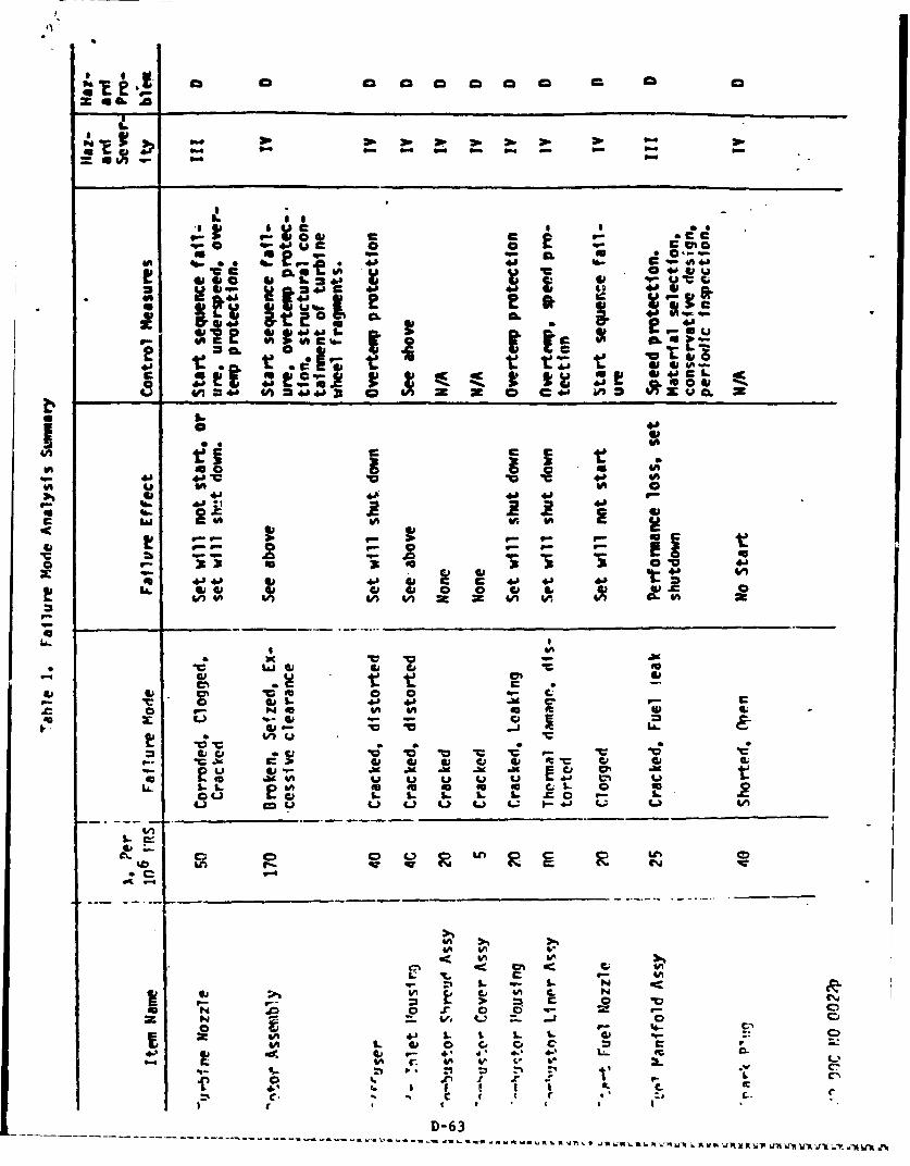
a CI
Ln
or- a.
~0 40U 40
2 S 0 - to aVI %.. 4. 4-h C..~ 84
4Aa@ c u 48A
c~ 4AV.vgo P- r- ~ P-o V
IC -P- OP.-w0 It a *
ft
L.. w. 41 ej W t
Ldi 4)r. MLJ C7
Gi. a- M U P L
4 4 -0
Li. C, Li U w LD
SS
14U41 1I
IA0 0 co C;Li4u 4.1, 6.. 4-: ,-
-- -. - . . A . - A ý T a ; a a ý - , Nw

30 30
CI 3 w-
c 0p4. 0 A v A d g
oo P- 4 -P.
2 "; f C 1
U~~C a .n. ! ~Etch "W. ;6m,* ~ ~ 1 g04a ee~~ w 'Ii w e
OM W-i 'P. B1p. a IL Bh
4 Z *4 X 0 4 C
so a S
to3* C
00 a
V.V c
rs L :0.,~ V41.
LL. ciV L. C
aca
C, edC
It. C.
41.. ~
*~ CD-64

p.op -
1• 3 'VI 4 -o 3 e'p-.I ES, . ° .
"M A 4.pU
op.
0 FA
.'C
.. it e 'Cu i ;, =
C ,
C U 4. .,C
313
S.. . . . . .. . . . . . _C
:,~~p c.• •J- I',•I4 I C * C
41.0 .l .- 4.
~~0 4A M 4.4A
rSC VC 0 tqp 0 aa a
ftV4A v 4 AVI V 6A AAE. GJr - C, 9-i0
+j, toc a co
C, F-. E)
W &i
LZ. .
40 4614- &M
%A W- I r P-C
D-65

* .
C3
foxl
" I ":•lb I .
-g
1. 6'
2 4.U1
4 S4
*1 L
U- 4l
~. p.
* *1e.
ocSiD.66
-- - -- -

APPSNDIX I - DISTRIBUTION LIST
No. of
AAdreamas a.i
U.S. Aramy Test and Evaluation CommandAM': ANSTZ-ST-S 4Aberdeen Provin8 Grrcnd, WD 21005-5055
CommanderU.S. Army Tank-Automotive CoumandATTN: ANSTA-CZIVarren. MI 48397-5000
ComanderU.S. Army Materiel CommandATTN: ANCS-3 105001 Eisenhover AveAlexandria, Va 22333-0001
CmmanderU.S. Army Ar•ment Research, Development, and
Ingiueer&n8 CenterATT: SCAR- 818Picatinny Arsenal, NJ 07806-5000
CommanderU.S. Army Natick Research, Development, and
Engineering CenterAT2I: STRNC-Slatick, MA 01760-5000
ComanderU.S. Army Missile CommandATTI: ANSMI-XORedstone, AL 35898-5000
CommanderU.S. Army Belvoir Research, Development, and
Engineering CenterATTN: STRBE-QFort Selvoir, Va 22060-5606
ComanierU.S. Army Laboratory CommandATTN: AMSLC-SOAdelphi, MD 20783-1145Commander
U.S. Army Armament, Munitions and Chemical CommandATTN: AMSMC-SFS IRock Island, I1 617'9-6C00
E-I
UI

No. of
CmanderU.$. Army Coiaunications and Ilectronics CinmandA1N: ANSEL-S-MSFort Noumouth, NJ 07703-5007
C•mmnderU.S. hrm Safety CenterAT21: PnSC-S8 2
Fort Rucker, AL 362762
CansderU.S. Ar Chemical Research, Developsent. and
t•gneer in8 Center
Aso: SMCCR--SFSAbeozden Proving Ground, MD 21010-5423
ComanderU.S. Army, White Sands Missile RangeAT25: STEPS-DP-EWhite Sands, Missile Range, NM 88002
Coander
U.S. AMy Yuma Proving GroundATTh: STSYP-SAFYoum, AZ 85364-9102
CamanderU.S. Army Dugvay Proving GroundATM: STJDP-SA1Dagway, UT 84022-6302
ComanderU.S. Army Defense Ammunition Center and SchoolATTI: SMCAC-DENSavanna, II, 61,Ž.4-9639
Project Manager, TRADEATT: AMCPM-TND-SPNaval Training CenterOrlando, 1L 32813-7100
E-2
===================================== .ltm.h

no. of- ~AAdLrUS ano- fii
Director
U.S. Army Ballistic Research LaboratoryAM. SLCBIR-DD-T (STUIO) 2
Aberdeen Proving Ground, MD 21005-5066
CmsnderU.S. Army Combat Systems Test ActivityATTN: STICS-AD-A I
8TUCS- go 6
Aberdeen Proving Ground, MD 21005-5059
AdministratorDefemne Technical Information Center
ATTI: DDA 2Caeron StationAlanadria, Va 22304-6145
Distribution unlimited.
E-3(Page E-4 Blank)