nerc filings to ferc dl...translate this page%pdf-1.6 %âãÏÓ 14845 0 obj >stream hÞ´ymo 7...
TRANSCRIPT
UNITED STATES OF AMERICA BEFORE THE
FEDERAL ENERGY REGULATORY COMMISSION
NORTH AMERICAN ELECTRIC ) Docket No. RD12-_____ RELIABILITY CORPORATION )
PETITION OF THE NORTH AMERICAN ELECTRIC RELIABILITY CORPORATION
FOR APPROVAL OF PROPOSED RELIABILITY STANDARD MOD-028-2 – AREA INTERCHANGE METHODOLOGY
Gerald W. Cauley President and Chief Executive Officer 3353 Peachtree Road NE Suite 600, North Tower Atlanta, GA 30326-1001 Charles A. Berardesco Senior Vice President and General Counsel North American Electric Reliability Corporation 1325 G Street, N.W., Suite 600 Washington, D.C. 20005 [email protected]
Holly A. Hawkins Assistant General Counsel for Standards and Critical Infrastructure Protection Stacey Tyrewala Attorney North American Electric Reliability
Corporation 1325 G Street, N.W., Suite 600 Washington, D.C. 20005 (202) 400-3000 (202) 644-8099– facsimile [email protected] [email protected]
August 24, 2012

i
TABLE OF CONTENTS
I. Executive Summary
II. Notices and Communications
III. Background
a. Regulatory Framework
b. NERC Reliability Standards Development Procedure
IV. Justification for Approval of the Proposed Reliability Standard
a. Basis and Purpose of Proposed Standard
b. Improvements to Standard in this Revision
c. Enforceability of the Proposed Reliability Standard
1. Violation Risk Factors (VRFs) and Violation Severity Levels (VSLs)
V. Summary of the Reliability Standard Development Proceedings
a. SAR Development
b. Overview of the Standard Drafting Team
c. First Posting and Initial Ballot
d. Recirculation Ballot
e. Board of Trustees Approval
VI. Conclusion
Exhibit A — Order No. 672 Criteria Exhibit B — Reliability Standard submitted for Approval Exhibit C — Implementation Plan for Reliability Standard submitted for Approval Exhibit D — Consideration of Comments Exhibit E — Record of Development of Proposed Reliability Standard Exhibit F — Standard Drafting Team Roster for NERC Standards Development Project INT-2011-01
1
UNITED STATES OF AMERICA BEFORE THE
FEDERAL ENERGY REGULATORY COMMISSION
NORTH AMERICAN ELECTRIC ) Docket No. RD12-____ RELIABILITY CORPORATION )
PETITION OF THE NORTH AMERICAN ELECTRIC RELIABILITY CORPORATION
FOR APPROVAL OF PROPOSED RELIABILITY STANDARD MOD-028-2 – AREA INTERCHANGE METHODOLOGY
The North American Electric Reliability Corporation (“NERC”)1 hereby requests
the Federal Energy Regulatory Commission (“FERC” or the “Commission”) to approve,
in accordance with Section 215(d)(1) of the Federal Power Act (“FPA”)2 and Section
39.5 of the Commission’s regulations, 18 C.F.R. § 39.5 (2012), proposed standard MOD-
028-2 as approved by the NERC Board of Trustees on February 9, 2012. The proposed
Reliability Standard provides clarification to the currently effective MOD-028-1 standard
on the timing and frequency of Total Transfer Capability (“TTC”) calculations needed for
Available Transfer Capability (“ATC”) calculations.
By this petition, NERC is requesting approval of the following:
approval of the proposed Reliability Standard which is included in Exhibit B, effective on the first day of the first calendar quarter after applicable regulatory approval or where no regulatory approval is required, on the first day of the first calendar quarter after Board approval.
approval of the implementation plan for the proposed Reliability Standard which is included in Exhibit C;
1 NERC has been certified by FERC as the electric reliability organization (“ERO”) in accordance with Section 215 of the Federal Power Act. The Commission certified NERC as the ERO in its order issued July 20, 2006 in Docket No. RR06-1-000. North American Electric Reliability Corp., 116 FERC ¶ 61,062 (2006) (“ERO Certification Order”). 2 16 U.S.C. § 824o (2012).

2
approval of the retirement of Reliability Standard, effective midnight immediately prior to the first day of the first calendar quarter after applicable regulatory approval or where no regulatory approval is required, on the first day of the first calendar quarter after Board approval.
I. EXECUTIVE SUMMARY
The proposed Reliability Standard represents an improvement over the currently-
effective Reliability Standard because it clarifies the timing and frequency of TTC
calculations needed for ATC calculations. The MOD-028-1 standard originally referred
to the current-day and next-day TTC values as “on-peak and off-peak intra-day and next
day.” In order to clear up a misinterpretation that this required specific on-peak and off-
peak load forecasts, Requirement R3 of the MOD-028-1 existing Reliability Standard
was modified to clarify language regarding load forecasting, to indicate that for days two
through 31, a daily load forecast is required (identical to the current standard); for months
two through 13, a monthly load forecast is required (identical to the current standard);
and for current-day and next-day, entities may use either a daily or hourly load forecast
(the language being clarified). The new language clarifies and is consistent with the
intent of the original requirement language, and does not materially change the standard.
II. NOTICES AND COMMUNICATIONS
Notices and communications with respect to this filing may be addressed to the
following:3
3 Persons to be included on the Commission’s service list are indicated with an asterisk. NERC requests waiver of the Commission’s rules and regulations to permit the inclusion of more than two people on the service list.

3
Gerald W. Cauley President and Chief Executive Officer 3353 Peachtree Road NE Suite 600, North Tower Atlanta, GA 30326-1001 Charles A. Berardesco* Senior Vice President and General Counsel North American Electric Reliability Corporation 1325 G Street, N.W., Suite 600 Washington, D.C. 20005 [email protected]
Holly A. Hawkins* Assistant General Counsel for Standards and Critical Infrastructure Protection Stacey Tyrewala* Attorney North American Electric Reliability
Corporation 1325 G Street, N.W., Suite 600 Washington, D.C. 20005 (202) 400-3000 (202) 644-8099– facsimile [email protected] [email protected]
III. BACKGROUND
a. Regulatory Framework
By enacting the Energy Policy Act of 2005,4 Congress entrusted the Commission
with the duties of approving and enforcing rules to ensure the reliability of the Nation’s
bulk power system, and with the duties of certifying an electric reliability organization
(“ERO”) that would be charged with developing and enforcing mandatory Reliability
Standards, subject to Commission approval. Section 215 of the FPA states that all users,
owners, and operators of the bulk power system in the United States will be subject to
Commission-approved Reliability Standards.5
Section 215(d)(5) of the FPA authorizes the Commission to order the ERO to
submit a new or modified Reliability Standard. Pursuant to Section 215(d)(2) of the FPA
and Section 39.5(c) of the Commission’s regulations, the Commission is required to give
due weight to the technical expertise of the ERO with respect to the content of a
4 16 U.S.C. § 824o (2012). 5 See Section 215(b)(1)(“All users, owners and operators of the bulk-power system shall comply with reliability standards that take effect under this section.”).

4
Reliability Standard. In Order No. 693, the Commission noted that it would defer to the
“technical expertise” of the ERO with respect to the content of a Reliability Standard and
explained that, through the use of directives, it provides guidance but does not dictate an
outcome. Rather, it will consider an equivalent alternative approach proposed by the
ERO provided that the ERO demonstrates that the alternative will address the
Commission’s underlying concern or goal as efficiently and effectively as the
Commission’s proposal, example, or directive.6
Section 39.5(a) of the Commission’s regulations requires the ERO to file with the
Commission for its approval each Reliability Standard that the ERO proposes to become
mandatory and enforceable in the United States, and each modification to a Reliability
Standard that the ERO proposes to be made effective. The Commission has the
regulatory responsibility to approve standards that protect the reliability of the bulk
power system and to ensure that such standards are just, reasonable, not unduly
discriminatory or preferential, and in the public interest.
Order No. 672 provides guidance on the factors the Commission will consider
when determining whether proposed Reliability Standards meet the statutory criteria to
ensure that they are just, reasonable, not unduly discriminatory or preferential and in the
public interest. Each of those factors is addressed in Exhibit A.
b. NERC Reliability Standards Development Procedure
NERC develops Reliability Standards in accordance with Section 300 (Reliability
Standards Development) of the NERC Rules of Procedure and the NERC Standard
Processes Manual, which is Appendix 3A to the NERC Rules of Procedure. In its ERO 6 See Mandatory Reliability Standards for the Bulk-Power System, Order No. 693, FERC Stats. & Regs. ¶ 31,242 at PP 31, 186-187, order on reh’g, Order No. 693-A, 120 FERC ¶ 61,053 (2007).
5
Certification Order, the Commission found that NERC’s proposed rules provide for
reasonable notice and opportunity for public comment, due process, openness, and a
balance of interests in developing Reliability Standards and thus satisfies certain of the
criteria for approving Reliability Standards. The development process is open to any
person or entity with a legitimate interest in the reliability of the bulk power system.
NERC considers the comments of all stakeholders, and a vote of stakeholders and the
NERC Board of Trustees is required to approve a Reliability Standard before the
Reliability Standard is submitted to the Commission for approval.
IV. JUSTIFICATION FOR APPROVAL OF THE PROPOSED RELIABILITY STANDARD MOD-028-2
a. Basis and Purpose of Reliability Standard — MOD-028-2
The primary purpose of the proposed standard is to increase consistency and
reliability in the development and documentation of Transfer Capability calculations for
short-term use performed by entities using the Area Interchange Methodology to support
analysis and system operations.
The currently effective MOD-028-1 Reliability Standard was filed on August 29,
2008 in Docket RM08-19-000 and approved by the Commission on November 24, 2009
in Order No. 729.7 The Modeling, Data, and Analysis Reliability Standards require
certain users, owners, and operators of the bulk power system to develop consistent
methodologies for the calculation of ATC or AFC. Three currently-effective NERC
Reliability Standards –MOD-028-1, MOD-029-1, and MOD-030-2—address three
different methodologies for calculating ATC, all of which produce predictable,
7Mandatory Reliability Standards for the Calculation of Available Transfer Capability, Capacity Benefit Margins, Transmission Reliability Margins, Total Transfer Capability, and Existing Transmission Commitments and Mandatory Reliability Standards for the Bulk-Power System, Final Rule, 129 FERC ¶ 61,155 (November 24, 2009).
6
sufficiently accurate, consistent, equivalent, and replicable results.8 MOD-028-1
describes the area interchange methodology for determining ATC. This Reliability
Standard only applies to Transmission Operators and Transmission Service Providers that
elect to implement this particular methodology as part of their compliance with MOD-
001-1a, Requirement R1, which requires each Transmission Operator to calculate ATC or
AFC for each ATC Path for those Facilities within its Transmission operating area using
one of the three methodologies referenced above.
In May 2011, NERC received a request for interpretation from Florida Power &
Light (FPL) of MOD-028-1, Requirement R3.1. FPL requested clarification of the
timing and frequency TTC calculations needed for ATC calculations. At its July 2011
meeting, the NERC Standards Committee determined that the request could not be
addressed through an interpretation, and that a modification to the standard may be
necessary. The Standards Committee identified a way of using the existing standards
development process to make a clarifying change to the standard in roughly the same
amount of time required to develop and approve an interpretation. That is, the existing
standards development process could be used, but the scope of standards development
would be limited to a very specific change that was expected to meet with stakeholder
consensus without the need for significant debate. In July 2011, the NERC Standards
Committee approved, with FPL’s consent, a recommendation to address FPL’s request
for interpretation through a minor revision to the MOD-028-1 Reliability Standard.
A standard drafting team was assembled for this project and directed by the
Standards Committee to submit both a Standards Authorization Request (SAR) and
proposed revisions to MOD-028-1 concurrently, addressing the issues raised in the 8 Order. No. 729 at P 51.

7
request for interpretation. Because the revisions are narrowly focused on addressing the
clarification requested by FPL, the Standards Committee approved waiving the initial 30-
day formal comment period and directed that the SAR and proposed revisions to the
standard be posted for a 45-day parallel comment period and ballot.
b. Improvements to Standard in this Revision
The MOD-028-1 standard originally referred to the current-day and next-day TTC
values as “on-peak and off-peak intra-day and next day.” However, this language was
interpreted as requiring specific on-peak and off-peak load forecasts. In fact, the intent
was to specify that for TTC used in current day and next-day ATC calculations, the load
forecast used should be consistent with the period being calculated (e.g., intra-day ATC
calculations should not be based on a monthly load forecast).
To address these concerns, Requirement R3 of the MOD-028-1 standard is
proposed to be modified to clarify language regarding load forecasting, to indicate that
for days two through 31, a daily load forecast is required (identical to the current
standard); for months two through 13, a monthly load forecast is required (identical to the
current standard); and for current-day and next-day, entities may use either a daily or
hourly load forecast (the language being clarified). The new language clarifies and is
consistent with the intent of the original requirement language, and does not materially
change the standard.
The VRFs for the MOD-028-2 standard are not proposed to be modified in this
filing, and are pending action by FERC. However, one minor errata correction is
proposed to the VSLs for Requirement R4 correcting an inadvertent reference to
8
Requirement R5. Other administrative modifications are proposed to the compliance
elements of the standard to bring it into conformance with current guidelines.
c. Enforceability of the Proposed Reliability Standard
The proposed Reliability Standard contains measures that support each standard
requirement by clearly identifying what is required and how the requirement will be
enforced. The VSLs also provide further guidance on the way NERC will enforce the
requirements of the standard.
i. Violation Risk Factors and Violation Severity Levels
Because the VRFs and VSLs were for the MOD-028-1 standard were either
approved by or are pending before the Commission and remain unchanged in this
proposed version 2 of the standard, NERC is not providing a comprehensive explanation
in this filing regarding how each VRF and VSL meets Commission guidelines. For a list
of the existing VRFs and VSLs, please see the MOD-028-2 standard in Exhibit B.
V. SUMMARY OF THE RELIABILITY STANDARD DEVELOPMENT
PROCEEDINGS
The development record for the proposed MOD-028-2 Reliability Standard is
summarized below. Exhibit D contains the Consideration of Comments Reports created
during the development standard. Exhibit E contains the record of development for the
proposed standard.
a. SAR Development
Project 2011-INT-01 was initiated on May 13, 2011, when FPL submitted a
request for interpretation of Requirement R3.1 asking for clarification of the required
performance and the conditions under which the performance of that requirement is

9
necessary. In July 2011, the NERC Standards Committee approved, with FPL’s consent,
the initiation of a standard develop project to address FPL’s request for interpretation
through a minor revision to the MOD-028-1 Reliability Standard.
b. Overview of the Standard Drafting Team
When evaluating proposed Reliability Standard, the Commission is expected to
give “due weight” to the technical expertise of the ERO.9 The technical expertise of the
ERO is derived from the SDT. For this project, the SDT consisted of five industry
experts with approximately 60 years collective experience. Each individual is considered
to be an expert in his field. Members of this standard drafting team provided a diversity
of experience, ranging across North America, including both the continental United
States and Canada. A detailed set of biographical information for each of the team
members is included along with the SDT roster in Exhibit F.
c. The First Posting and Initial Ballot
The first draft of the proposed MOD-028-2 standard was posted from October 2,
2011 to November 16, 2011 for a concurrent comment and ballot period. NERC received
9 sets of comments including comments from 51 different individuals from
approximately 43 companies representing all 10 industry segments. A majority of
comments indicated that the changes made to the standard resolved the questions raised
in the request for interpretation. Several commenters expressed concern over edits made
to the compliance section of the standard. However, these changes are intended only to
provide guidance on compliance with the standard and will not become mandatory and
enforceable when the proposed MOD-028-2 Reliability Standard is approved by FERC.
Several other comments questioned minor edits to the data retention section of the 9 Section 215(d)(2) of the Federal Power Act; 16 U.S.C. § 824o(d)(2) (2011).
10
standard. The paragraph that was added to the Data Retention section of the standard is
intended to notify entities of this responsibility and is not specific to MOD-028-2; this
paragraph is being added to all standards as they are revised.
The ballot period took place between November 7, 2011 and November 16, 2011.
The standard received a quorum of 88.05% and an affirmative vote of 85.53%.
d. Recirculation Ballot
A recirculation ballot was held from December 12, 2011 to December 22, 2011.
The standard received a 90.10% quorum and a 92.49% approval.
e. Board of Trustees Approval
The final draft of the proposed Reliability Standard was presented to the NERC
Board of Trustees for approval on February 9, 2012. The Board of Trustees approved the
proposed Reliability Standard, and NERC staff was authorized to file with applicable
regulatory authorities.
VI. CONCLUSION
For the reasons set forth above, NERC respectfully requests that the Commission:
approve the proposed MOD-028-2 Reliability Standard which is included in Exhibit B, effective on the first day of the first calendar quarter after applicable regulatory approval or where no regulatory approval is required, on the first day of the first calendar quarter after Board approval.
approve the implementation plan for Reliability Standard MOD-028-2 which is included in Exhibit C;
approve the retirement of the MOD-028-1Reliability Standard, effective
midnight immediately prior to the first day of the first calendar quarter after applicable regulatory approval or where no regulatory approval is required, on the first day of the first calendar quarter after Board approval.
11
Respectfully submitted,
Gerald W. Cauley President and Chief Executive Officer 3353 Peachtree Road NE Suite 600, North Tower Atlanta, GA 30326-1001 Charles A. Berardesco Senior Vice President and General Counsel North American Electric Reliability Corporation 1325 G Street, N.W., Suite 600 Washington, D.C. 20005 [email protected]
/s/ Holly A. Hawkins Holly A. Hawkins Assistant General Counsel for Standards and Critical Infrastructure Protection Stacey Tyrewala Attorney North American Electric Reliability
Corporation 1325 G Street, N.W., Suite 600 Washington, D.C. 20005 (202) 400-3000 (202) 644-8099– facsimile [email protected] [email protected]

CERTIFICATE OF SERVICE I hereby certify that I have served a copy of the foregoing document upon all parties
listed on the official service list compiled by the Secretary in this proceeding.
Dated at Washington, D.C. this 24th day of August, 2012.
/s/ Holly A. Hawkins Holly A. Hawkins
Attorney for North American Electric Reliability Corporation

2
EXHIBIT A
Order No. 672 Criteria
In Order No. 672,10 the Commission identified a number of criteria it will use to
analyze Reliability Standards proposed for approval to ensure they are just, reasonable,
not unduly discriminatory or preferential, and in the public interest. The discussion
below identifies these factors and explains how the proposed Reliability Standard has met
or exceeded the criteria:
1. Proposed Reliability Standards must be designed to achieve a specified reliability goal and must contain a technically sound means to achieve that goal.11
Proposed Reliability Standard MOD-028-2 is one of a suite of Reliability
Standards (MOD-001-1, MOD-028-1, MOD-029-1 and MOD-030-1) that are designed to
work together to ensure that Transmission Service Providers and Transmission Operators
maintain awareness of available transmission system capability and future flows on their
own systems as well as those of their neighbors. Historically, differences in
implementations of ATC methodologies and a lack of coordination between 10 Rules Concerning Certification of the Electric Reliability Organization; and Procedures for the Establishment, Approval, and Enforcement of Electric Reliability Standards, Order No. 672, FERC Stats. & Regs. ¶ 31,204, order on reh’g, Order No. 672-A, FERC Stats. & Regs. ¶ 31,212 (2006). 11 Order No. 672 at P 321. The proposed Reliability Standard must address a reliability concern that falls within the requirements of section 215 of the FPA. That is, it must provide for the reliable operation of Bulk-Power System facilities. It may not extend beyond reliable operation of such facilities or apply to other facilities. Such facilities include all those necessary for operating an interconnected electric energy transmission network, or any portion of that network, including control systems. The proposed Reliability Standard may apply to any design of planned additions or modifications of such facilities that is necessary to provide for reliable operation. It may also apply to Cybersecurity protection. Order No. 672 at P 324. The proposed Reliability Standard must be designed to achieve a specified reliability goal and must contain a technically sound means to achieve this goal. Although any person may propose a topic for a Reliability Standard to the ERO, in the ERO’s process, the specific proposed Reliability Standard should be developed initially by persons within the electric power industry and community with a high level of technical expertise and be based on sound technical and engineering criteria. It should be based on actual data and lessons learned from past operating incidents, where appropriate. The process for ERO approval of a proposed Reliability Standard should be fair and open to all interested persons.

3
Transmission Service Providers has resulted in cases where systems have been oversold,
resulting in potential or actual System Operating Limit (SOL) and Interconnection
Reliability Operating Limit (IROL) violations. This standard works to ensure that the
occurrence of such scenarios is minimized by specifying the parameters of the Area
Interchange Methodology such that ATC values closely match actual remaining system
capability. The proposed MOD-028-2 standard adds clarity to one requirement of the
currently-effective MOD-028-1 standard by ensuring that for TTCs used in current and
next-day ATC calculations, the load forecast used is consistent with the period being
calculated (e.g., intra-day ATC calculations should not be based on a monthly load
forecast).
2. Proposed Reliability Standards must be applicable only to users, owners and operators of the bulk power system, and must be clear and unambiguous as to what is required and who is required to comply.12
The MOD-028-2 Reliability Standard is applicable only to users, owners and
operators of the bulk power system, and not others. The proposed standard applies to
Transmission Operators and Transmission Service Providers, and the action required by
the proposed standard is expressly stated.
3. A proposed Reliability Standard must include clear and understandable consequences and a range of penalties (monetary and/or non-monetary) for a violation. 13
The VRFs and VSLs for MOD-028-2 were not altered during this revision of the
standard from those assigned to MOD-028-1. The VRFS for MOD-028-1 are pending
12 Order No. 672 at P 322. The proposed Reliability Standard may impose a requirement on any user, owner, or operator of such facilities, but not on others. Order No. 672 at P 325. The proposed Reliability Standard should be clear and unambiguous regarding what is required and who is required to comply. Users, owners, and operators of the Bulk-Power System must know what they are required to do to maintain reliability. 13 Order No. 672 at P 326. The possible consequences, including range of possible penalties, for violating a proposed Reliability Standard should be clear and understandable by those who must comply.
4
before FERC in Docket No. RM08-19-002. One minor errata change was made to the
VSL of Requirement R4 to correct an inadvertent reference to Requirement R5. For a list
of the existing VRFs and VSLs, please see Exhibit B.
4. A proposed Reliability Standard must identify clear and objective criterion or measure for compliance, so that it can be enforced in a consistent and non-preferential manner. 14
Each Requirement in the proposed MOD-028-2 Reliability Standard is supported
by a measure that clearly identifies what is required and how the requirement will be
enforced. These thirteen measures that will ensure the Requirements are clearly
administered for enforcement in a consistent manner and without prejudice to any party
were approved by the Commission in Order No. 749. Administrative modifications were
made to the compliance elements of the proposed MOD-028-2 standard to bring it into
conformance with current guidelines, but no substantive changes were made to these
compliance elements.
5. Proposed Reliability Standards should achieve a reliability goal effectively and efficiently — but do not necessarily have to reflect “best practices” without regard to implementation cost or historical regional infrastructure design.15
The proposed Reliability Standard helps the industry achieve the stated reliability
goal effectively and efficiently. While some entities may be required to modify their
current implementation approach to comply with the standard, NERC does not believe
that implementation costs will be unduly burdensome when considering the increase in
14 Order No. 672 at P 327. There should be a clear criterion or measure of whether an entity is in compliance with a proposed Reliability Standard. It should contain or be accompanied by an objective measure of compliance so that it can be enforced and so that enforcement can be applied in a consistent and non-preferential manner. 15 Order No. 672 at P 328. The proposed Reliability Standard does not necessarily have to reflect the optimal method, or “best practice,” for achieving its reliability goal without regard to implementation cost or historical regional infrastructure design. It should however achieve its reliability goal effectively and efficiently.

5
consistency and transparency expected through the implementation of the Area
Interchange Methodology as presented.
6. Proposed Reliability Standards cannot be “lowest common denominator,” i.e., cannot reflect a compromise that does not adequately protect Bulk-Power System reliability. Proposed Reliability Standards can consider costs to implement for smaller entities, but not at consequences of less than excellence in operating system reliability.16
The MOD-028-2 Reliability Standard does not reflect a “lowest common
denominator” approach. The proposed standard represents an improvement over version
1 of the standard because it specifies that for TTCs used in current day and next-day ATC
calculations, the load forecast used should be consistent with the period being calculated
(e.g., intra-day ATC calculations should not be based on a monthly load forecast).
The MOD-028-2 Reliability Standard will apply equally to all applicable entities
in a consistent manner. While the proposed standard likely will result in some applicable
entities being required to modify their systems to implement the methodology described
within this standard, the standard does not impose requirements that are completely new
or unfamiliar to the industry.
7. Proposed Reliability Standards must be designed to apply throughout North America to the maximum extent achievable with a single Reliability Standard while not favoring one geographic area or regional model. It should take into
16 Order No. 672 at P 329. The proposed Reliability Standard must not simply reflect a compromise in the ERO’s Reliability Standard development process based on the least effective North American practice — the so-called “lowest common denominator” — if such practice does not adequately protect Bulk-Power System reliability. Although FERC will give due weight to the technical expertise of the ERO, we will not hesitate to remand a proposed Reliability Standard if we are convinced it is not adequate to protect reliability. Order No. 672 at P 330. A proposed Reliability Standard may take into account the size of the entity that must comply with the Reliability Standard and the cost to those entities of implementing the proposed Reliability Standard. However, the ERO should not propose a “lowest common denominator” Reliability Standard that would achieve less than excellence in operating system reliability solely to protect against reasonable expenses for supporting this vital national infrastructure. For example, a small owner or operator of the Bulk-Power System must bear the cost of complying with each Reliability Standard that applies to it.
6
account regional variations in the organization and corporate structures of transmission owners and operators, variations in generation fuel type and ownership patterns, and regional variations in market design if these affect the proposed Reliability Standard.17
NERC has developed the MOD-028-2 Reliability Standard to apply to all of
North America.
8. Proposed Reliability Standards should cause no undue negative effect on competition or restriction of the grid beyond any restriction necessary for reliability.18
The proposed MOD-028-2 Reliability Standard has no undue negative effect on
competition. It also does not unreasonably restrict ATC on the bulk power system
beyond any restriction necessary for reliability and does not limit use of the bulk power
system in an unduly preferential manner. It does not create an undue advantage for one
competitor over another. The focus of the proposed Reliability Standard is to address
only the reliability aspects of ATC and not to address the commercial aspects of available
transmission system capability with the exception of ensuring commercial transmission
availability closely matches actual remaining transmission capability.
9. The implementation time for the proposed Reliability Standard is reasonable.19
17 Order No. 672 at P 331. A proposed Reliability Standard should be designed to apply throughout the interconnected North American Bulk-Power System, to the maximum extent this is achievable with a single Reliability Standard. The proposed Reliability Standard should not be based on a single geographic or regional model but should take into account geographic variations in grid characteristics, terrain, weather, and other such factors; it should also take into account regional variations in the organizational and corporate structures of transmission owners and operators, variations in generation fuel type and ownership patterns, and regional variations in market design if these affect the proposed Reliability Standard. 18 Order No. 672 at P 332. As directed by section 215 of the FPA, FERC itself will give special attention to the effect of a proposed Reliability Standard on competition. The ERO should attempt to develop a proposed Reliability Standard that has no undue negative effect on competition. Among other possible considerations, a proposed Reliability Standard should not unreasonably restrict available transmission capability on the Bulk-Power System beyond any restriction necessary for reliability and should not limit use of the Bulk-Power System in an unduly preferential manner. It should not create an undue advantage for one competitor over another. 19 Order No. 672 at P 333. In considering whether a proposed Reliability Standard is just and reasonable, FERC will consider also the timetable for implementation of the new requirements, including how the proposal balances any urgency in the need to implement it against the reasonableness of the time allowed

7
The proposed effective date for the standard is just and reasonable and appropriately
balances the urgency in the need to implement the standard against the reasonableness of
the time allowed for those who must comply to develop necessary procedures, software,
facilities, staffing or other relevant capability.
This will allow applicable entities adequate time to ensure compliance with the
requirements. The proposed effective date is explained in the proposed Implementation
Plan, attached as Exhibit C.
10. The Reliability Standard was developed in an open and fair manner and in accordance with the Commission-approved Reliability Standard development process.20
The proposed Reliability Standard was developed in accordance with NERC’s
Commission-approved, ANSI- accredited processes for developing and approving
Reliability Standards (for a more thorough review, please see the complete development
history included as Exhibit E).
These processes included, among other things, multiple comment periods, pre-
ballot review periods, and balloting periods. Additionally, all drafting team meetings
were properly noticed and open to the public. The initial and recirculation ballots both
achieved a quorum and exceeded the required ballot pool approval levels.
11. NERC must explain any balancing of vital public interests in the development of proposed Reliability Standards.21
for those who must comply to develop the necessary procedures, software, facilities, staffing or other relevant capability. 20 Order No. 672 at P 334. Further, in considering whether a proposed Reliability Standard meets the legal standard of review, we will entertain comments about whether the ERO implemented its Commission-approved Reliability Standard development process for the development of the particular proposed Reliability Standard in a proper manner, especially whether the process was open and fair. However, we caution that we will not be sympathetic to arguments by interested parties that choose, for whatever reason, not to participate in the ERO’s Reliability Standard development process if it is conducted in good faith in accordance with the procedures approved by FERC. 21 Order No. 672 at P 335. Finally, we understand that at times development of a proposed Reliability Standard may require that a particular reliability goal must be balanced against other vital public interests,
8
NERC does not believe there are competing public interests with respect to the
request for approval of this proposed standard.
12. Proposed Reliability Standards must consider any other appropriate factors.22
The proposed MOD-028-2 Reliability Standard satisfies the general criteria specified
by the Commission. NERC is not proposing any additional factors for consideration to
support adoption of the proposed standard.
such as environmental, social and other goals. We expect the ERO to explain any such balancing in its application for approval of a proposed Reliability Standard. 22 Order No. 672 at P 323. In considering whether a proposed Reliability Standard is just and reasonable, we will consider the following general factors, as well as other factors that are appropriate for the particular Reliability Standard proposed.

Exhibit B
Reliability Standard submitted for Approval
Standard MOD-028-2 — Area In te rchange Methodology
Adopted b y the Board of Trus tees : February 9, 2012 Page 1 o f 16
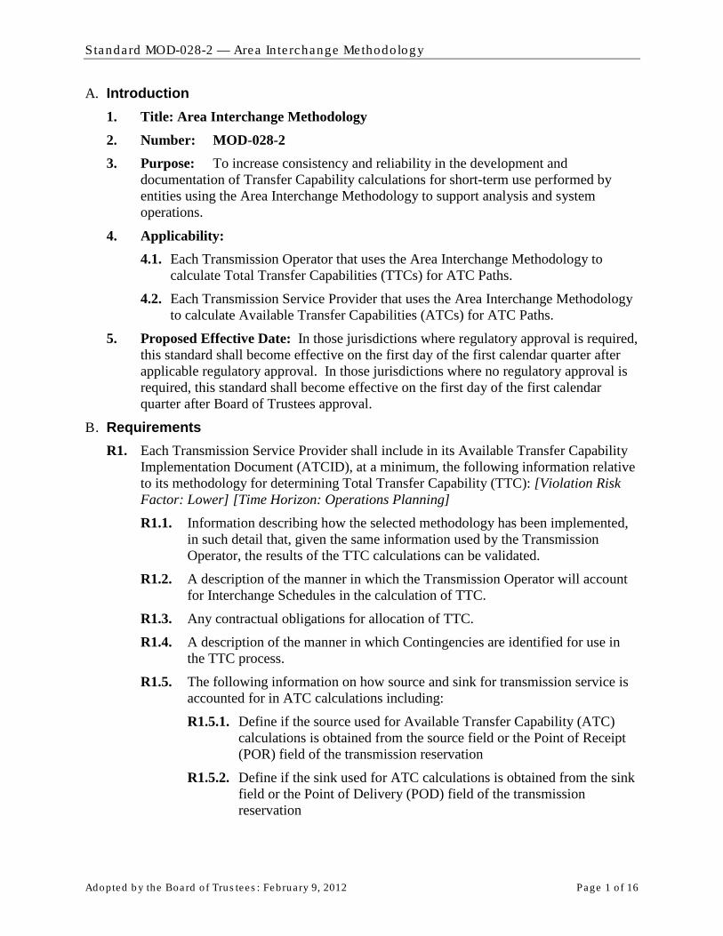
A. Introduction 1. Title: Area Interchange Methodology 2. Number: MOD-028-2 3. Purpose: To increase consistency and reliability in the development and
documentation of Transfer Capability calculations for short-term use performed by entities using the Area Interchange Methodology to support analysis and system operations.
4. Applicability: 4.1. Each Transmission Operator that uses the Area Interchange Methodology to
calculate Total Transfer Capabilities (TTCs) for ATC Paths.
4.2. Each Transmission Service Provider that uses the Area Interchange Methodology to calculate Available Transfer Capabilities (ATCs) for ATC Paths.
5. Proposed Effective Date: In those jurisdictions where regulatory approval is required, this standard shall become effective on the first day of the first calendar quarter after applicable regulatory approval. In those jurisdictions where no regulatory approval is required, this standard shall become effective on the first day of the first calendar quarter after Board of Trustees approval.
B. Requirements R1. Each Transmission Service Provider shall include in its Available Transfer Capability
Implementation Document (ATCID), at a minimum, the following information relative to its methodology for determining Total Transfer Capability (TTC): [Violation Risk Factor: Lower] [Time Horizon: Operations Planning] R1.1. Information describing how the selected methodology has been implemented,
in such detail that, given the same information used by the Transmission Operator, the results of the TTC calculations can be validated.
R1.2. A description of the manner in which the Transmission Operator will account for Interchange Schedules in the calculation of TTC.
R1.3. Any contractual obligations for allocation of TTC.
R1.4. A description of the manner in which Contingencies are identified for use in the TTC process.
R1.5. The following information on how source and sink for transmission service is accounted for in ATC calculations including:
R1.5.1. Define if the source used for Available Transfer Capability (ATC) calculations is obtained from the source field or the Point of Receipt (POR) field of the transmission reservation
R1.5.2. Define if the sink used for ATC calculations is obtained from the sink field or the Point of Delivery (POD) field of the transmission reservation

Standard MOD-028-2 — Area In te rchange Methodology
Adopted b y the Board of Trus tees : February 9, 2012 Page 2 o f 16
R1.5.3. The source/sink or POR/POD identification and mapping to the model.
R1.5.4. If the Transmission Service Provider’s ATC calculation process involves a grouping of generation, the ATCID must identify how these generators participate in the group.
R2. When calculating TTC for ATC Paths, the Transmission Operator shall use a Transmission model that contains all of the following: [Violation Risk Factor: Lower] [Time Horizon: Operations Planning] R2.1. Modeling data and topology of its Reliability Coordinator’s area of
responsibility. Equivalent representation of radial lines and facilities 161 kV or below is allowed.
R2.2. Modeling data and topology (or equivalent representation) for immediately adjacent and beyond Reliability Coordination areas.
R2.3. Facility Ratings specified by the Generator Owners and Transmission Owners.
R3. When calculating TTCs for ATC Paths, the Transmission Operator shall include the following data for the Transmission Service Provider’s area. The Transmission Operator shall also include the following data associated with Facilities that are explicitly represented in the Transmission model, as provided by adjacent Transmission Service Providers and any other Transmission Service Providers with which coordination agreements have been executed: [Violation Risk Factor: Lower] [Time Horizon: Operations Planning]
R3.1. For TTCs, use the following (as well as any other values and additional parameters as specified in the ATCID):
R3.1.1. Expected generation and Transmission outages, additions, and retirements, included as specified in the ATCID.
R3.1.2. A daily or hourly load forecast for TTCs used in current-day and next-day ATC calculations.
R3.1.3. A daily load forecast for TTCs used in ATC calculations for days two through 31.
R3.1.4. A monthly load forecast for TTCs used in ATC calculations for months two through 13 months TTCs.
R3.1.5. Unit commitment and dispatch order, to include all designated network resources and other resources that are committed or have the legal obligation to run, (within or out of economic dispatch) as they are expected to run.
R4. When calculating TTCs for ATC Paths, the Transmission Operator shall meet all of the following conditions: [Violation Risk Factor: Lower] [Time Horizon: Operations Planning] R4.1. Use all Contingencies meeting the criteria described in the ATCID.
R4.2. Respect any contractual allocations of TTC.

Standard MOD-028-2 — Area In te rchange Methodology
Adopted b y the Board of Trus tees : February 9, 2012 Page 3 o f 16
R4.3. Include, for each time period, the Firm Transmission Service expected to be scheduled as specified in the ATCID (filtered to reduce or eliminate duplicate impacts from transactions using Transmission service from multiple Transmission Service Providers) for the Transmission Service Provider, all adjacent Transmission Service Providers, and any Transmission Service Providers with which coordination agreements have been executed modeling the source and sink as follows:
- If the source, as specified in the ATCID, has been identified in the reservation and it is discretely modeled in the Transmission Service Provider’s Transmission model, use the discretely modeled point as the source.
- If the source, as specified in the ATCID, has been identified in the reservation and the point can be mapped to an “equivalence” or “aggregate representation” in the Transmission Service Provider’s Transmission model, use the modeled equivalence or aggregate as the source.
- If the source, as specified in the ATCID, has been identified in the reservation and the point cannot be mapped to a discretely modeled point, an “equivalence,” or an “aggregate representation” in the Transmission Service Provider’s Transmission model, use the immediately adjacent Balancing Authority associated with the Transmission Service Provider from which the power is to be received as the source.
- If the source, as specified in the ATCID, has not been identified in the reservation, use the immediately adjacent Balancing Authority associated with the Transmission Service Provider from which the power is to be received as the source.
- If the sink, as specified in the ATCID, has been identified in the reservation and it is discretely modeled in the Transmission Service Provider’s Transmission model, use the discretely modeled point shall as the sink.
- If the sink, as specified in the ATCID, has been identified in the reservation and the point can be mapped to an “equivalence” or “aggregate representation” in the Transmission Service Provider’s Transmission model, use the modeled equivalence or aggregate as the sink.
- If the sink, as specified in the ATCID, has been identified in the reservation and the point can not be mapped to a discretely modeled point, an “equivalence,” or an “aggregate representation” in the Transmission Service Provider’s Transmission model, use the immediately adjacent Balancing Authority associated with the Transmission Service Provider to which the power is to be delivered as the sink.
- If the sink, as specified in the ATCID, has not been identified in the reservation, use the immediately adjacent Balancing Authority associated with the Transmission Service Provider to which the power is being delivered as the sink.

Standard MOD-028-2 — Area In te rchange Methodology
Adopted b y the Board of Trus tees : February 9, 2012 Page 4 o f 16
R5. Each Transmission Operator shall establish TTC for each ATC Path as defined below: [Violation Risk Factor: Lower] [Time Horizon: Operations Planning] R5.1. At least once within the seven calendar days prior to the specified period for
TTCs used in hourly and daily ATC calculations.
R5.2. At least once per calendar month for TTCs used in monthly ATC calculations.
R5.3. Within 24 hours of the unexpected outage of a 500 kV or higher transmission Facility or a transformer with a low-side voltage of 200 kV or higher for TTCs in effect during the anticipated duration of the outage, provided such outage is expected to last 24 hours or longer.
R6. Each Transmission Operator shall establish TTC for each ATC Path using the following process: [Violation Risk Factor: Lower] [Time Horizon: Operations Planning] R6.1. Determine the incremental Transfer Capability for each ATC Path by
increasing generation and/or decreasing load within the source Balancing Authority area and decreasing generation and/or increasing load within the sink Balancing Authority area until either:
- A System Operating Limit is reached on the Transmission Service Provider’s system, or
- A SOL is reached on any other adjacent system in the Transmission model that is not on the study path and the distribution factor is 5% or greater1
R6.2. If the limit in step R6.1 can not be reached by adjusting any combination of load or generation, then set the incremental Transfer Capability by the results of the case where the maximum adjustments were applied.
.
R6.3. Use (as the TTC) the lesser of:
− The sum of the incremental Transfer Capability and the impacts of Firm Transmission Services, as specified in the Transmission Service Provider’s ATCID, that were included in the study model, or
− The sum of Facility Ratings of all ties comprising the ATC Path.
R6.4. For ATC Paths whose capacity uses jointly-owned or allocated Facilities, limit TTC for each Transmission Service Provider so the TTC does not exceed each Transmission Service Provider’s contractual rights.
R7. The Transmission Operator shall provide the Transmission Service Provider of that ATC Path with the most current value for TTC for that ATC Path no more than: [Violation Risk Factor: Lower] [Time Horizon: Operations Planning]
R7.1. One calendar day after its determination for TTCs used in hourly and daily ATC calculations.
R7.2. Seven calendar days after its determination for TTCs used in monthly ATC calculations.
1 The Transmission operator may honor distribution factors less than 5% if desired.

Standard MOD-028-2 — Area In te rchange Methodology
Adopted b y the Board of Trus tees : February 9, 2012 Page 5 o f 16
R8. When calculating Existing Transmission Commitments (ETCs) for firm commitments (ETCF
ETC
) for all time periods for an ATC Path the Transmission Service Provider shall use the following algorithm: [Violation Risk Factor: Lower] [Time Horizon: Operations Planning]
F = NITSF + GFF + PTPF + RORF + OS
Where: F
NITSF is the firm capacity set aside for Network Integration Transmission Service (including the capacity used to serve bundled load within the Transmission Service Provider’s area with external sources) on ATC Paths that serve as interfaces with other Balancing Authorities.
GFF is the firm capacity set aside for Grandfathered Firm Transmission Service and contracts for energy and/or Transmission Service, where executed prior to the effective date of a Transmission Service Provider’s Open Access Transmission Tariff or safe harbor tariff on ATC Paths that serve as interfaces with other Balancing Authorities.
PTPF is the firm capacity reserved for confirmed Point-to-Point Transmission Service.
RORF is the capacity reserved for roll-over rights for Firm Transmission Service contracts granting Transmission Customers the right of first refusal to take or continue to take Transmission Service when the Transmission Customer’s Transmission Service contract expires or is eligible for renewal.
OSF is the firm capacity reserved for any other service(s), contract(s), or agreement(s) not specified above using Firm Transmission Service, including any other firm adjustments to reflect impacts from other ATC Paths of the Transmission Service Provider as specified in the ATCID.
R9. When calculating ETC for non-firm commitments (ETCNF
ETC
) for all time periods for an ATC Path the Transmission Service Provider shall use the following algorithm: [Violation Risk Factor: Lower] [Time Horizon: Operations Planning]
NF = NITSNF + GFNF + PTPNF + OS
NF
Where: NITSNF is the non-firm capacity set aside for Network Integration Transmission
Service (i.e., secondary service , including the capacity used to serve bundled load within the Transmission Service Provider’s area with external sources) reserved on ATC Paths that serve as interfaces with other Balancing Authorities.
GFNF is the non-firm capacity reserved for Grandfathered Non-Firm Transmission Service and contracts for energy and/or Transmission Service, where executed prior to the effective date of a Transmission Service Provider’s Open Access Transmission Tariff or safe harbor tariff on ATC Paths that serve as interfaces with other Balancing Authorities.
Standard MOD-028-2 — Area In te rchange Methodology
Adopted b y the Board of Trus tees : February 9, 2012 Page 6 o f 16
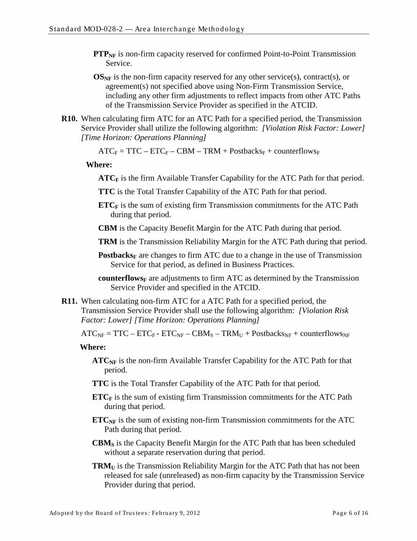
PTPNF is non-firm capacity reserved for confirmed Point-to-Point Transmission Service.
OSNF is the non-firm capacity reserved for any other service(s), contract(s), or agreement(s) not specified above using Non-Firm Transmission Service, including any other firm adjustments to reflect impacts from other ATC Paths of the Transmission Service Provider as specified in the ATCID.
R10. When calculating firm ATC for an ATC Path for a specified period, the Transmission Service Provider shall utilize the following algorithm: [Violation Risk Factor: Lower] [Time Horizon: Operations Planning]
ATCF = TTC – ETCF – CBM – TRM + PostbacksF + counterflowsF
Where: ATCF is the firm Available Transfer Capability for the ATC Path for that period.
TTC is the Total Transfer Capability of the ATC Path for that period.
ETCF is the sum of existing firm Transmission commitments for the ATC Path during that period.
CBM is the Capacity Benefit Margin for the ATC Path during that period.
TRM is the Transmission Reliability Margin for the ATC Path during that period.
PostbacksF are changes to firm ATC due to a change in the use of Transmission Service for that period, as defined in Business Practices.
counterflowsF are adjustments to firm ATC as determined by the Transmission Service Provider and specified in the ATCID.
R11. When calculating non-firm ATC for a ATC Path for a specified period, the Transmission Service Provider shall use the following algorithm: [Violation Risk Factor: Lower] [Time Horizon: Operations Planning] ATCNF = TTC – ETCF - ETCNF – CBMS – TRMU + PostbacksNF + counterflowsNF
Where: ATCNF is the non-firm Available Transfer Capability for the ATC Path for that
period.
TTC is the Total Transfer Capability of the ATC Path for that period.
ETCF is the sum of existing firm Transmission commitments for the ATC Path during that period.
ETCNF is the sum of existing non-firm Transmission commitments for the ATC Path during that period.
CBMS is the Capacity Benefit Margin for the ATC Path that has been scheduled without a separate reservation during that period.
TRMU is the Transmission Reliability Margin for the ATC Path that has not been released for sale (unreleased) as non-firm capacity by the Transmission Service Provider during that period.
Standard MOD-028-2 — Area In te rchange Methodology
Adopted b y the Board of Trus tees : February 9, 2012 Page 7 o f 16
PostbacksNF are changes to non-firm ATC due to a change in the use of Transmission Service for that period, as defined in Business Practices.
counterflowsNF are adjustments to non-firm ATC as determined by the Transmission Service Provider and specified in the ATCID.
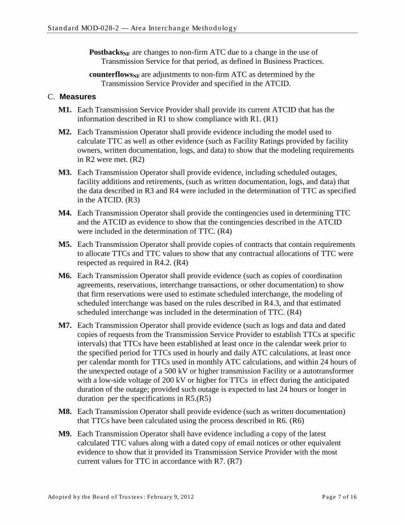
C. Measures M1. Each Transmission Service Provider shall provide its current ATCID that has the
information described in R1 to show compliance with R1. (R1)
M2. Each Transmission Operator shall provide evidence including the model used to calculate TTC as well as other evidence (such as Facility Ratings provided by facility owners, written documentation, logs, and data) to show that the modeling requirements in R2 were met. (R2)
M3. Each Transmission Operator shall provide evidence, including scheduled outages, facility additions and retirements, (such as written documentation, logs, and data) that the data described in R3 and R4 were included in the determination of TTC as specified in the ATCID. (R3)
M4. Each Transmission Operator shall provide the contingencies used in determining TTC and the ATCID as evidence to show that the contingencies described in the ATCID were included in the determination of TTC. (R4)
M5. Each Transmission Operator shall provide copies of contracts that contain requirements to allocate TTCs and TTC values to show that any contractual allocations of TTC were respected as required in R4.2. (R4)
M6. Each Transmission Operator shall provide evidence (such as copies of coordination agreements, reservations, interchange transactions, or other documentation) to show that firm reservations were used to estimate scheduled interchange, the modeling of scheduled interchange was based on the rules described in R4.3, and that estimated scheduled interchange was included in the determination of TTC. (R4)
M7. Each Transmission Operator shall provide evidence (such as logs and data and dated copies of requests from the Transmission Service Provider to establish TTCs at specific intervals) that TTCs have been established at least once in the calendar week prior to the specified period for TTCs used in hourly and daily ATC calculations, at least once per calendar month for TTCs used in monthly ATC calculations, and within 24 hours of the unexpected outage of a 500 kV or higher transmission Facility or a autotransformer with a low-side voltage of 200 kV or higher for TTCs in effect during the anticipated duration of the outage; provided such outage is expected to last 24 hours or longer in duration per the specifications in R5.(R5)
M8. Each Transmission Operator shall provide evidence (such as written documentation) that TTCs have been calculated using the process described in R6. (R6)
M9. Each Transmission Operator shall have evidence including a copy of the latest calculated TTC values along with a dated copy of email notices or other equivalent evidence to show that it provided its Transmission Service Provider with the most current values for TTC in accordance with R7. (R7)

Standard MOD-028-2 — Area In te rchange Methodology
Adopted b y the Board of Trus tees : February 9, 2012 Page 8 o f 16
M10. The Transmission Service Provider shall demonstrate compliance with R8 by recalculating firm ETC
M11. The Transmission Service Provider shall demonstrate compliance with R9 by recalculating non-firm ETC for any specific time period as described in (MOD-001 R2), using the algorithm defined in R9 and with data used to calculate the specified value for the designated time period. The data used must meet the requirements specified in MOD-028-2 and the ATCID. To account for differences that may occur when recalculating the value (due to mixing automated and manual processes), any recalculated value that is within +/- 15% or 15 MW, whichever is greater, of the originally calculated value, is evidence that the Transmission Service Provider used the algorithm in R8 to calculate its non-firm ETC. (R9)
for any specific time period as described in (MOD-001 R2), using the algorithm defined in R8 and with data used to calculate the specified value for the designated time period. The data used must meet the requirements specified in MOD-028-2 and the ATCID. To account for differences that may occur when recalculating the value (due to mixing automated and manual processes), any recalculated value that is within +/- 15% or 15 MW, whichever is greater, of the originally calculated value, is evidence that the Transmission Service Provider used the algorithm in R8 to calculate its firm ETC. (R8)
M12. Each Transmission Service Provider shall produce the supporting documentation for the processes used to implement the algorithm that calculates firm ATCs, as required in R10. Such documentation must show that only the variables allowed in R10 were used to calculate firm ATCs, and that the processes use the current values for the variables as determined in the requirements or definitions. Note that any variable may legitimately be zero if the value is not applicable or calculated to be zero (such as counterflows, TRM, CBM, etc…). The supporting documentation may be provided in the same form and format as stored by the Transmission Service Provider. (R10)
M13. Each Transmission Service Provider shall produce the supporting documentation for the processes used to implement the algorithm that calculates non-firm ATCs, as required in R11. Such documentation must show that only the variables allowed in R11 were used to calculate non-firm ATCs, and that the processes use the current values for the variables as determined in the requirements or definitions. Note that any variable may legitimately be zero if the value is not applicable or calculated to be zero (such as counterflows, TRM, CBM, etc…). The supporting documentation may be provided in the same form and format as stored by the Transmission Service Provider. (R11)
D. Compliance 1. Compliance Monitoring Process
1.1. Compliance Enforcement Authority For entities that do not work for the Regional Entity, the Regional Entity shall serve as the Compliance Enforcement Authority.
For functional entities that work for their Regional Entity, the ERO or a Regional Entity approved by the ERO and FERC or other applicable governmental authorities shall serve as the Compliance Enforcement Authority.

Standard MOD-028-2 — Area In te rchange Methodology
Adopted b y the Board of Trus tees : February 9, 2012 Page 9 o f 16
1.2. Data Retention
The following evidence retention periods identify the period of time an entity is required to retain specific evidence to demonstrate compliance. For instances where the evidence retention period specified below is shorter than the time since the last audit, the Compliance Enforcement Authority may ask an entity to provide other evidence to show that it was compliant for the full time period since the last audit.
The Transmission Operator and Transmission Service Provider shall keep data or evidence to show compliance as identified below unless directed by its Compliance Enforcement Authority to retain specific evidence for a longer period of time as part of an investigation:
- The Transmission Service Provider shall retain its current, in force ATCID and any prior versions of the ATCID that were in force since the last compliance audit to show compliance with R1.
- The Transmission Operator shall have its latest model used to calculate TTC and evidence of the previous version to show compliance with R2.
- The Transmission Operator shall retain evidence to show compliance with R3 for the most recent 12 months or until the model used to calculate TTC is updated, whichever is longer.
- The Transmission Operator shall retain evidence to show compliance with R4, R5, R6 and R7 for the most recent 12 months.
- The Transmission Service Provider shall retain evidence to show compliance in calculating hourly values required in R8 and R9 for the most recent 14 days; evidence to show compliance in calculating daily values required in R8 and R9 for the most recent 30 days; and evidence to show compliance in calculating monthly values required in R8 and R9 for the most recent 60 days.
- The Transmission Service Provider shall retain evidence to show compliance with R10 and R11 for the most recent 12 months.
- If a Transmission Service Provider or Transmission Operator is found non-compliant, it shall keep information related to the non-compliance until found compliant.
- The Compliance Enforcement Authority shall keep the last audit records and all requested and submitted subsequent audit records.
1.3. Compliance Monitoring and Enforcement Processes: The following processes may be used:
- Compliance Audits
- Self-Certifications
- Spot Checking
- Compliance Violation Investigations
- Self-Reporting
- Complaints

Standard MOD-028-2 — Area In te rchange Methodology
Adopted b y the Board of Trus tees : February 9, 2012 Page 10 of 16
1.4. Additional Compliance Information None.
Standard MOD-028-2 — Area In te rchange Methodology
Adopted b y the Board of Trus tees : February 9, 2012 Page 11 of 16
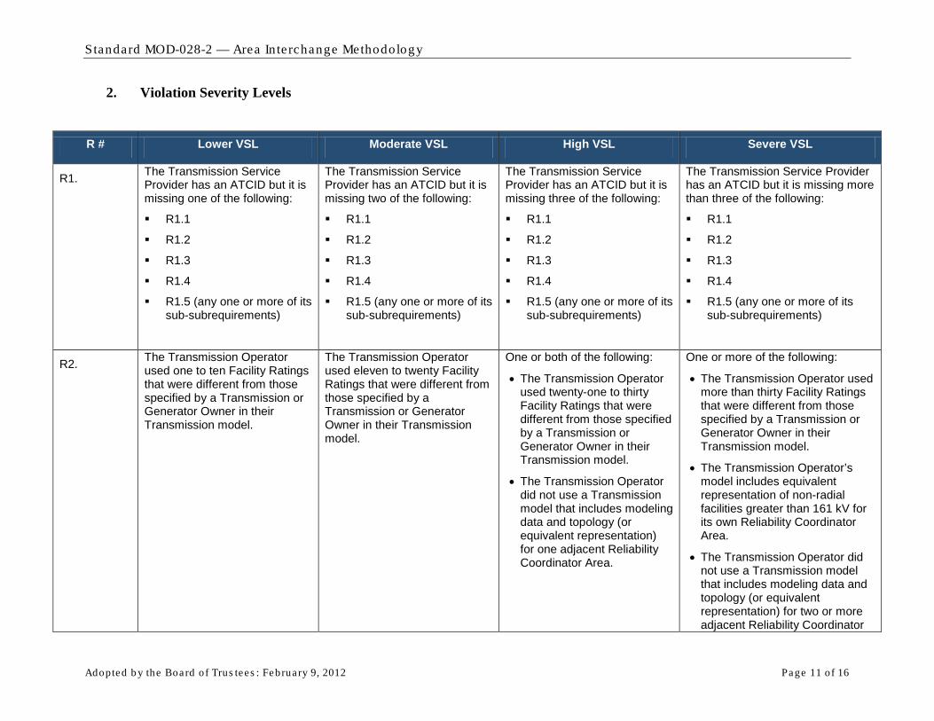
2. Violation Severity Levels
R # Lower VSL Moderate VSL High VSL Severe VSL
R1. The Transmission Service Provider has an ATCID but it is missing one of the following:
R1.1
R1.2
R1.3
R1.4
R1.5 (any one or more of its sub-subrequirements)
The Transmission Service Provider has an ATCID but it is missing two of the following:
R1.1
R1.2
R1.3
R1.4
R1.5 (any one or more of its sub-subrequirements)
The Transmission Service Provider has an ATCID but it is missing three of the following:
R1.1
R1.2
R1.3
R1.4
R1.5 (any one or more of its sub-subrequirements)
The Transmission Service Provider has an ATCID but it is missing more than three of the following:
R1.1
R1.2
R1.3
R1.4
R1.5 (any one or more of its sub-subrequirements)
R2. The Transmission Operator used one to ten Facility Ratings that were different from those specified by a Transmission or Generator Owner in their Transmission model.
The Transmission Operator used eleven to twenty Facility Ratings that were different from those specified by a Transmission or Generator Owner in their Transmission model.
One or both of the following:
• The Transmission Operator used twenty-one to thirty Facility Ratings that were different from those specified by a Transmission or Generator Owner in their Transmission model.
• The Transmission Operator did not use a Transmission model that includes modeling data and topology (or equivalent representation) for one adjacent Reliability Coordinator Area.
One or more of the following:
• The Transmission Operator used more than thirty Facility Ratings that were different from those specified by a Transmission or Generator Owner in their Transmission model.
• The Transmission Operator’s model includes equivalent representation of non-radial facilities greater than 161 kV for its own Reliability Coordinator Area.
• The Transmission Operator did not use a Transmission model that includes modeling data and topology (or equivalent representation) for two or more adjacent Reliability Coordinator

Standard MOD-028-2 — Area In te rchange Methodology
Adopted b y the Board of Trus tees : February 9, 2012 Page 12 of 16
R # Lower VSL Moderate VSL High VSL Severe VSL
Areas.
R3. The Transmission Operator did not include in the TTC process one to ten expected generation and Transmission outages, additions or retirements as specified in the ATCID.
The Transmission Operator did not include in the TTC process eleven to twenty-five expected generation and Transmission outages, additions or retirements as specified in the ATCID.
The Transmission Operator did not include in the TTC process twenty-six to fifty expected generation and Transmission outages, additions or retirements as specified in the ATCID.
One or more of the following:
• The Transmission Operator did not include in the TTC process more than fifty expected generation and Transmission outages, additions or retirements as specified in the ATCID.
• The Transmission Operator did not include the Load forecast or unit commitment in its TTC calculation as described in R3.
R4.
The Transmission Operator did not model reservations’ sources or sinks as described in R4.3 for more than zero reservations, but not more than 5% of all reservations; or 1 reservation, whichever is greater.
The Transmission Operator did not model reservations’ sources or sinks as described in R4.3 for more than 5%, but not more than 10% of all reservations; or 2 reservations, whichever is greater.
The Transmission Operator did not model reservations’ sources or sinks as described in R4.3 for more than 10%, but not more than 15% of all reservations; or 3 reservations, whichever is greater.
One or more of the following:
• The Transmission Operator did not include in the TTC calculation the contingencies that met the criteria described in the ATCID.
• The Transmission Operator did not respect contractual allocations of TTC.
• The Transmission Operator did not model reservations’ sources or sinks as described in R4.3 for more than 15% of all reservations; or more than 3 reservations, whichever is greater.
• The Transmission Operator did not use firm reservations to estimate interchange or did not

Standard MOD-028-2 — Area In te rchange Methodology
Adopted b y the Board of Trus tees : February 9, 2012 Page 13 of 16
R # Lower VSL Moderate VSL High VSL Severe VSL
utilize that estimate in the TTC calculation as described in R4.3.
R5. One or more of the following:
• The Transmission Operator did not establish TTCs for use in hourly or daily ATCs within 7 calendar days but did establish the values within 10 calendar days
• The Transmission Operator did not establish TTCs for use in monthly ATCs during a calendar month but did establish the values within the next consecutive calendar month
One or more of the following:
• The Transmission Operator did not establish TTCs for use in hourly or daily ATCs in 10 calendar days but did establish the values within 13 calendar days
• The Transmission Operator did not establish TTCs for use in monthly ATCs during a two consecutive calendar month period but did establish the values within the third consecutive calendar month
One or more of the following:
• The Transmission Operator did not establish TTCs for used in hourly or daily ATCs in 13 calendar days but did establish the values within 16 calendar days
• The Transmission Operator did not establish TTCs for use in monthly ATCs during a three consecutive calendar month period but did establish the values within the fourth consecutive calendar month
One or more of the following:
• The Transmission Operator did not establish TTCs for used in hourly or daily ATCs in 16 calendar days
• The Transmission Operator did not establish TTCs for use in monthly ATCs during a four or more consecutive calendar month period
• The Transmission Operator did not establish TTCs within 24 hrs of the triggers defined in R5.3
R6. N/A N/A N/A
The Transmission Operator did not calculate TTCs per the process specified in R6.
R7. One or more of the following:
• The Transmission Operator provided its Transmission Service Provider with its ATC Path TTCs used in hourly or daily ATC calculations more than one calendar day after their determination, but not been more than two calendar days after their determination.
• The Transmission Operator
One or more of the following:
• The Transmission Operator provided its Transmission Service Provider with its ATC Path TTCs used in hourly or daily ATC calculations more than two calendar days after their determination, but not been more than three calendar days after their determination.
• The Transmission Operator
One or more of the following:
• The Transmission Operator provided its Transmission Service Provider with its ATC Path TTCs used in hourly or daily ATC calculations more than three calendar days after their determination, but not been more than four calendar days after their determination.
• The Transmission Operator
One or more of the following:
• The Transmission Operator provided its Transmission Service Provider with its ATC Path TTCs used in hourly or daily ATC calculations more than four calendar days after their determination.
• The Transmission Operator did not provide its Transmission Service Provider with its ATC Path TTCs used in hourly or
Standard MOD-028-2 — Area In te rchange Methodology
Adopted b y the Board of Trus tees : February 9, 2012 Page 14 of 16
R # Lower VSL Moderate VSL High VSL Severe VSL
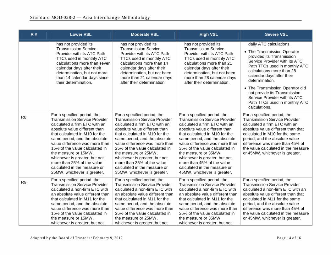
has not provided its Transmission Service Provider with its ATC Path TTCs used in monthly ATC calculations more than seven calendar days after their determination, but not more than 14 calendar days since their determination.
has not provided its Transmission Service Provider with its ATC Path TTCs used in monthly ATC calculations more than 14 calendar days after their determination, but not been more than 21 calendar days after their determination.
has not provided its Transmission Service Provider with its ATC Path TTCs used in monthly ATC calculations more than 21 calendar days after their determination, but not been more than 28 calendar days after their determination.
daily ATC calculations.
• The Transmission Operator provided its Transmission Service Provider with its ATC Path TTCs used in monthly ATC calculations more than 28 calendar days after their determination.
• The Transmission Operator did not provide its Transmission Service Provider with its ATC Path TTCs used in monthly ATC calculations.
R8. For a specified period, the Transmission Service Provider calculated a firm ETC with an absolute value different than that calculated in M10 for the same period, and the absolute value difference was more than 15% of the value calculated in the measure or 15MW, whichever is greater, but not more than 25% of the value calculated in the measure or 25MW, whichever is greater.
For a specified period, the Transmission Service Provider calculated a firm ETC with an absolute value different than that calculated in M10 for the same period, and the absolute value difference was more than 25% of the value calculated in the measure or 25MW, whichever is greater, but not more than 35% of the value calculated in the measure or 35MW, whichever is greater.
For a specified period, the Transmission Service Provider calculated a firm ETC with an absolute value different than that calculated in M10 for the same period, and the absolute value difference was more than 35% of the value calculated in the measure or 35MW, whichever is greater, but not more than 45% of the value calculated in the measure or 45MW, whichever is greater.
For a specified period, the Transmission Service Provider calculated a firm ETC with an absolute value different than that calculated in M10 for the same period, and the absolute value difference was more than 45% of the value calculated in the measure or 45MW, whichever is greater.
R9. For a specified period, the Transmission Service Provider calculated a non-firm ETC with an absolute value different than that calculated in M11 for the same period, and the absolute value difference was more than 15% of the value calculated in the measure or 15MW, whichever is greater, but not
For a specified period, the Transmission Service Provider calculated a non-firm ETC with an absolute value different than that calculated in M11 for the same period, and the absolute value difference was more than 25% of the value calculated in the measure or 25MW, whichever is greater, but not
For a specified period, the Transmission Service Provider calculated a non-firm ETC with an absolute value different than that calculated in M11 for the same period, and the absolute value difference was more than 35% of the value calculated in the measure or 35MW, whichever is greater, but not
For a specified period, the Transmission Service Provider calculated a non-firm ETC with an absolute value different than that calculated in M11 for the same period, and the absolute value difference was more than 45% of the value calculated in the measure or 45MW, whichever is greater.

Standard MOD-028-2 — Area In te rchange Methodology
Adopted b y the Board of Trus tees : February 9, 2012 Page 15 of 16
R # Lower VSL Moderate VSL High VSL Severe VSL
more than 25% of the value calculated in the measure or 25MW, whichever is greater.
more than 35% of the value calculated in the measure or 35MW, whichever is greater...
more than 45% of the value calculated in the measure or 45MW, whichever is greater.
R10. The Transmission Service Provider did not use all the elements defined in R10 when determining firm ATC, or used additional elements, for more than zero ATC Paths, but not more than 5% of all ATC Paths or 1 ATC Path (whichever is greater).
The Transmission Service Provider did not use all the elements defined in R10 when determining firm ATC, or used additional elements, for more than 5% of all ATC Paths or 1 ATC Path (whichever is greater), but not more than 10% of all ATC Paths or 2 ATC Paths (whichever is greater).
The Transmission Service Provider did not use all the elements defined in R10 when determining firm ATC, or used additional elements, for more than 10% of all ATC Paths or 2 ATC Paths (whichever is greater), but not more than 15% of all ATC Paths or 3 ATC Paths (whichever is greater).
The Transmission Service Provider did not use all the elements defined in R10 when determining firm ATC, or used additional elements, for more than 15% of all ATC Paths or more than 3 ATC Paths (whichever is greater).
R11. The Transmission Service Provider did not use all the elements defined in R11 when determining non-firm ATC, or used additional elements, for more than zero ATC Paths, but not more than 5% of all ATC Paths or 1 ATC Path (whichever is greater).
The Transmission Service Provider did not use all the elements defined in R11 when determining non-firm ATC, or used additional elements, for more than 5% of all ATC Paths or 1 ATC Path (whichever is greater), but not more than 10% of all ATC Paths or 2 ATC Paths (whichever is greater).
The Transmission Service Provider did not use all the elements defined in R11 when determining non-firm ATC, or used additional elements, for more than 10% of all ATC Paths or 2 ATC Paths (whichever is greater), but not more than 15% of all ATC Paths or 3 ATC Paths (whichever is greater).
The Transmission Service Provider did not use all the elements defined in R11 when determining non-firm ATC, or used additional elements, for more than 15% of all ATC Paths or more than 3 ATC Paths (whichever is greater).

Standard MOD-028-2 — Area In te rchange Methodology
Adopted b y the Board of Trus tees : February 9, 2012 Page 16 of 16
Version History Version Date Action Change Tracking
1 August 26, 2008 Adopted by the Board of Trustees
2 February 9, 2012 Adopted by the Board of Trustees
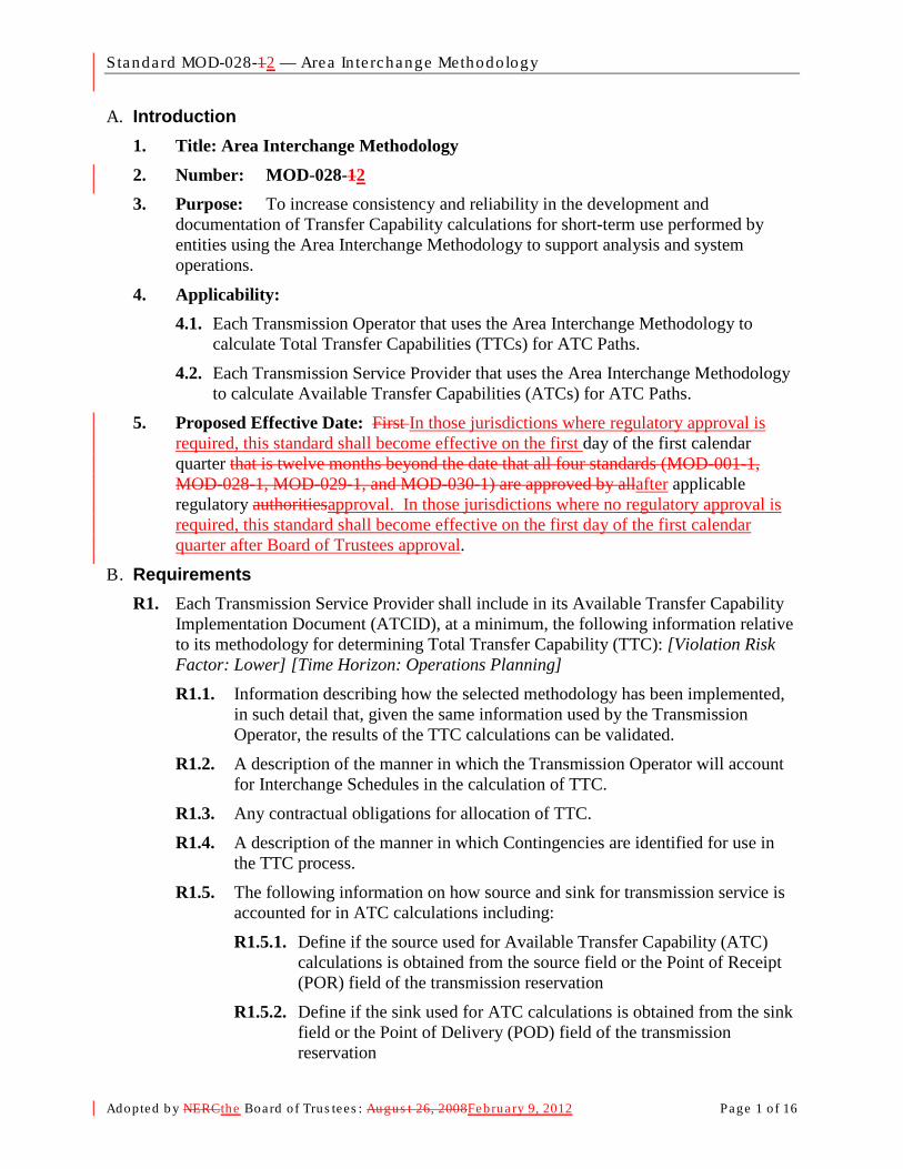
Standard MOD-028-12 — Area In te rchange Methodology
Adopted b y NERCthe Board of Trus tees : Augus t 26, 2008February 9, 2012 Page 1 o f 16
A. Introduction 1. Title: Area Interchange Methodology 2. Number: MOD-028-12 3. Purpose: To increase consistency and reliability in the development and
documentation of Transfer Capability calculations for short-term use performed by entities using the Area Interchange Methodology to support analysis and system operations.
4. Applicability: 4.1. Each Transmission Operator that uses the Area Interchange Methodology to
calculate Total Transfer Capabilities (TTCs) for ATC Paths.
4.2. Each Transmission Service Provider that uses the Area Interchange Methodology to calculate Available Transfer Capabilities (ATCs) for ATC Paths.
5. Proposed Effective Date: First In those jurisdictions where regulatory approval is required, this standard shall become effective on the first day of the first calendar quarter that is twelve months beyond the date that all four standards (MOD-001-1, MOD-028-1, MOD-029-1, and MOD-030-1) are approved by allafter applicable regulatory authoritiesapproval. In those jurisdictions where no regulatory approval is required, this standard shall become effective on the first day of the first calendar quarter after Board of Trustees approval.
B. Requirements R1. Each Transmission Service Provider shall include in its Available Transfer Capability
Implementation Document (ATCID), at a minimum, the following information relative to its methodology for determining Total Transfer Capability (TTC): [Violation Risk Factor: Lower] [Time Horizon: Operations Planning] R1.1. Information describing how the selected methodology has been implemented,
in such detail that, given the same information used by the Transmission Operator, the results of the TTC calculations can be validated.
R1.2. A description of the manner in which the Transmission Operator will account for Interchange Schedules in the calculation of TTC.
R1.3. Any contractual obligations for allocation of TTC.
R1.4. A description of the manner in which Contingencies are identified for use in the TTC process.
R1.5. The following information on how source and sink for transmission service is accounted for in ATC calculations including:
R1.5.1. Define if the source used for Available Transfer Capability (ATC) calculations is obtained from the source field or the Point of Receipt (POR) field of the transmission reservation
R1.5.2. Define if the sink used for ATC calculations is obtained from the sink field or the Point of Delivery (POD) field of the transmission reservation
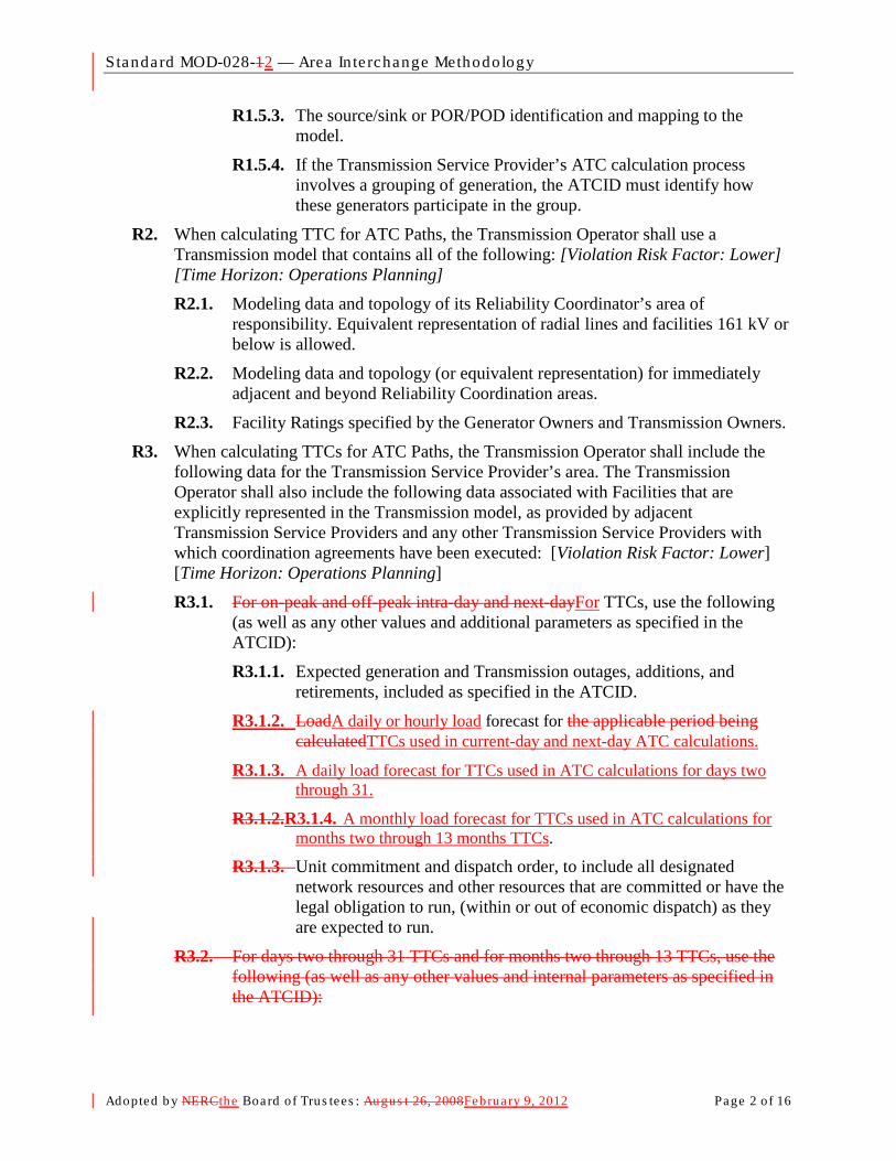
Standard MOD-028-12 — Area In te rchange Methodology
Adopted b y NERCthe Board of Trus tees : Augus t 26, 2008February 9, 2012 Page 2 o f 16
R1.5.3. The source/sink or POR/POD identification and mapping to the model.
R1.5.4. If the Transmission Service Provider’s ATC calculation process involves a grouping of generation, the ATCID must identify how these generators participate in the group.
R2. When calculating TTC for ATC Paths, the Transmission Operator shall use a Transmission model that contains all of the following: [Violation Risk Factor: Lower] [Time Horizon: Operations Planning] R2.1. Modeling data and topology of its Reliability Coordinator’s area of
responsibility. Equivalent representation of radial lines and facilities 161 kV or below is allowed.
R2.2. Modeling data and topology (or equivalent representation) for immediately adjacent and beyond Reliability Coordination areas.
R2.3. Facility Ratings specified by the Generator Owners and Transmission Owners.
R3. When calculating TTCs for ATC Paths, the Transmission Operator shall include the following data for the Transmission Service Provider’s area. The Transmission Operator shall also include the following data associated with Facilities that are explicitly represented in the Transmission model, as provided by adjacent Transmission Service Providers and any other Transmission Service Providers with which coordination agreements have been executed: [Violation Risk Factor: Lower] [Time Horizon: Operations Planning]
R3.1. For on-peak and off-peak intra-day and next-dayFor TTCs, use the following (as well as any other values and additional parameters as specified in the ATCID):
R3.1.1. Expected generation and Transmission outages, additions, and retirements, included as specified in the ATCID.
R3.1.2. LoadA daily or hourly load forecast for the applicable period being calculatedTTCs used in current-day and next-day ATC calculations.
R3.1.3. A daily load forecast for TTCs used in ATC calculations for days two through 31.
R3.1.2.R3.1.4. A monthly load forecast for TTCs used in ATC calculations for months two through 13 months TTCs.
R3.1.3. Unit commitment and dispatch order, to include all designated network resources and other resources that are committed or have the legal obligation to run, (within or out of economic dispatch) as they are expected to run.
R3.2. For days two through 31 TTCs and for months two through 13 TTCs, use the following (as well as any other values and internal parameters as specified in the ATCID):

Standard MOD-028-12 — Area In te rchange Methodology
Adopted b y NERCthe Board of Trus tees : Augus t 26, 2008February 9, 2012 Page 3 o f 16
R3.2.1. Expected generation and Transmission outages, additions, and Retirements, included as specified in the ATCID.
R3.2.2. Daily load forecast for the days two through 31 TTCs being calculated and monthly forecast for months two through 13 months TTCs being calculated.
R3.2.3.R3.1.5. Unit commitment and dispatch order, to include all designated network resources and other resources that are committed or have the legal obligation to run, (within or out of economic dispatch) as they are expected to run.
R4. When calculating TTCs for ATC Paths, the Transmission Operator shall meet all of the following conditions: [Violation Risk Factor: Lower] [Time Horizon: Operations Planning] R4.1. Use all Contingencies meeting the criteria described in the ATCID.
R4.2. Respect any contractual allocations of TTC.
R4.3. Include, for each time period, the Firm Transmission Service expected to be scheduled as specified in the ATCID (filtered to reduce or eliminate duplicate impacts from transactions using Transmission service from multiple Transmission Service Providers) for the Transmission Service Provider, all adjacent Transmission Service Providers, and any Transmission Service Providers with which coordination agreements have been executed modeling the source and sink as follows:
- If the source, as specified in the ATCID, has been identified in the reservation and it is discretely modeled in the Transmission Service Provider’s Transmission model, use the discretely modeled point as the source.
- If the source, as specified in the ATCID, has been identified in the reservation and the point can be mapped to an “equivalence” or “aggregate representation” in the Transmission Service Provider’s Transmission model, use the modeled equivalence or aggregate as the source.
- If the source, as specified in the ATCID, has been identified in the reservation and the point cannot be mapped to a discretely modeled point, an “equivalence,” or an “aggregate representation” in the Transmission Service Provider’s Transmission model, use the immediately adjacent Balancing Authority associated with the Transmission Service Provider from which the power is to be received as the source.
- If the source, as specified in the ATCID, has not been identified in the reservation, use the immediately adjacent Balancing Authority associated with the Transmission Service Provider from which the power is to be received as the source.
- If the sink, as specified in the ATCID, has been identified in the reservation and it is discretely modeled in the Transmission Service Provider’s Transmission model, use the discretely modeled point shall as the sink.

Standard MOD-028-12 — Area In te rchange Methodology
Adopted b y NERCthe Board of Trus tees : Augus t 26, 2008February 9, 2012 Page 4 o f 16
- If the sink, as specified in the ATCID, has been identified in the reservation and the point can be mapped to an “equivalence” or “aggregate representation” in the Transmission Service Provider’s Transmission model, use the modeled equivalence or aggregate as the sink.
- If the sink, as specified in the ATCID, has been identified in the reservation and the point can not be mapped to a discretely modeled point, an “equivalence,” or an “aggregate representation” in the Transmission Service Provider’s Transmission model, use the immediately adjacent Balancing Authority associated with the Transmission Service Provider to which the power is to be delivered as the sink.
- If the sink, as specified in the ATCID, has not been identified in the reservation, use the immediately adjacent Balancing Authority associated with the Transmission Service Provider to which the power is being delivered as the sink.
R5. Each Transmission Operator shall establish TTC for each ATC Path as defined below: [Violation Risk Factor: Lower] [Time Horizon: Operations Planning] R5.1. At least once within the seven calendar days prior to the specified period for
TTCs used in hourly and daily ATC calculations.
R5.2. At least once per calendar month for TTCs used in monthly ATC calculations.
R5.3. Within 24 hours of the unexpected outage of a 500 kV or higher transmission Facility or a transformer with a low-side voltage of 200 kV or higher for TTCs in effect during the anticipated duration of the outage, provided such outage is expected to last 24 hours or longer.
R6. Each Transmission Operator shall establish TTC for each ATC Path using the following process: [Violation Risk Factor: Lower] [Time Horizon: Operations Planning] R6.1. Determine the incremental Transfer Capability for each ATC Path by
increasing generation and/or decreasing load within the source Balancing Authority area and decreasing generation and/or increasing load within the sink Balancing Authority area until either:
- A System Operating Limit is reached on the Transmission Service Provider’s system, or
- A SOL is reached on any other adjacent system in the Transmission model that is not on the study path and the distribution factor is 5% or greater1
R6.2. If the limit in step R6.1 can not be reached by adjusting any combination of load or generation, then set the incremental Transfer Capability by the results of the case where the maximum adjustments were applied.
.
R6.3. Use (as the TTC) the lesser of:
1 The Transmission operator may honor distribution factors less than 5% if desired.

Standard MOD-028-12 — Area In te rchange Methodology
Adopted b y NERCthe Board of Trus tees : Augus t 26, 2008February 9, 2012 Page 5 o f 16
− The sum of the incremental Transfer Capability and the impacts of Firm Transmission Services, as specified in the Transmission Service Provider’s ATCID, that were included in the study model, or
− The sum of Facility Ratings of all ties comprising the ATC Path.
R6.4. For ATC Paths whose capacity uses jointly-owned or allocated Facilities, limit TTC for each Transmission Service Provider so the TTC does not exceed each Transmission Service Provider’s contractual rights.
R7. The Transmission Operator shall provide the Transmission Service Provider of that ATC Path with the most current value for TTC for that ATC Path no more than: [Violation Risk Factor: Lower] [Time Horizon: Operations Planning]
R7.1. One calendar day after its determination for TTCs used in hourly and daily ATC calculations.
R7.2. Seven calendar days after its determination for TTCs used in monthly ATC calculations.
R8. When calculating Existing Transmission Commitments (ETCs) for firm commitments (ETCF
ETC
) for all time periods for an ATC Path the Transmission Service Provider shall use the following algorithm: [Violation Risk Factor: Lower] [Time Horizon: Operations Planning]
F = NITSF + GFF + PTPF + RORF + OS
Where: F
NITSF is the firm capacity set aside for Network Integration Transmission Service (including the capacity used to serve bundled load within the Transmission Service Provider’s area with external sources) on ATC Paths that serve as interfaces with other Balancing Authorities.
GFF is the firm capacity set aside for Grandfathered Firm Transmission Service and contracts for energy and/or Transmission Service, where executed prior to the effective date of a Transmission Service Provider’s Open Access Transmission Tariff or safe harbor tariff on ATC Paths that serve as interfaces with other Balancing Authorities.
PTPF is the firm capacity reserved for confirmed Point-to-Point Transmission Service.
RORF is the capacity reserved for roll-over rights for Firm Transmission Service contracts granting Transmission Customers the right of first refusal to take or continue to take Transmission Service when the Transmission Customer’s Transmission Service contract expires or is eligible for renewal.
OSF is the firm capacity reserved for any other service(s), contract(s), or agreement(s) not specified above using Firm Transmission Service, including any other firm adjustments to reflect impacts from other ATC Paths of the Transmission Service Provider as specified in the ATCID.

Standard MOD-028-12 — Area In te rchange Methodology
Adopted b y NERCthe Board of Trus tees : Augus t 26, 2008February 9, 2012 Page 6 o f 16
R9. When calculating ETC for non-firm commitments (ETCNF
ETC
) for all time periods for an ATC Path the Transmission Service Provider shall use the following algorithm: [Violation Risk Factor: Lower] [Time Horizon: Operations Planning]
NF = NITSNF + GFNF + PTPNF + OS
NF
Where: NITSNF is the non-firm capacity set aside for Network Integration Transmission
Service (i.e., secondary service , including the capacity used to serve bundled load within the Transmission Service Provider’s area with external sources) reserved on ATC Paths that serve as interfaces with other Balancing Authorities.
GFNF is the non-firm capacity reserved for Grandfathered Non-Firm Transmission Service and contracts for energy and/or Transmission Service, where executed prior to the effective date of a Transmission Service Provider’s Open Access Transmission Tariff or safe harbor tariff on ATC Paths that serve as interfaces with other Balancing Authorities.
PTPNF is non-firm capacity reserved for confirmed Point-to-Point Transmission Service.
OSNF is the non-firm capacity reserved for any other service(s), contract(s), or agreement(s) not specified above using Non-Firm Transmission Service, including any other firm adjustments to reflect impacts from other ATC Paths of the Transmission Service Provider as specified in the ATCID.
R10. When calculating firm ATC for an ATC Path for a specified period, the Transmission Service Provider shall utilize the following algorithm: [Violation Risk Factor: Lower] [Time Horizon: Operations Planning]
ATCF = TTC – ETCF – CBM – TRM + PostbacksF + counterflowsF
Where: ATCF is the firm Available Transfer Capability for the ATC Path for that period.
TTC is the Total Transfer Capability of the ATC Path for that period.
ETCF is the sum of existing firm Transmission commitments for the ATC Path during that period.
CBM is the Capacity Benefit Margin for the ATC Path during that period.
TRM is the Transmission Reliability Margin for the ATC Path during that period.
PostbacksF are changes to firm ATC due to a change in the use of Transmission Service for that period, as defined in Business Practices.
counterflowsF are adjustments to firm ATC as determined by the Transmission Service Provider and specified in the ATCID.
R11. When calculating non-firm ATC for a ATC Path for a specified period, the Transmission Service Provider shall use the following algorithm: [Violation Risk Factor: Lower] [Time Horizon: Operations Planning]
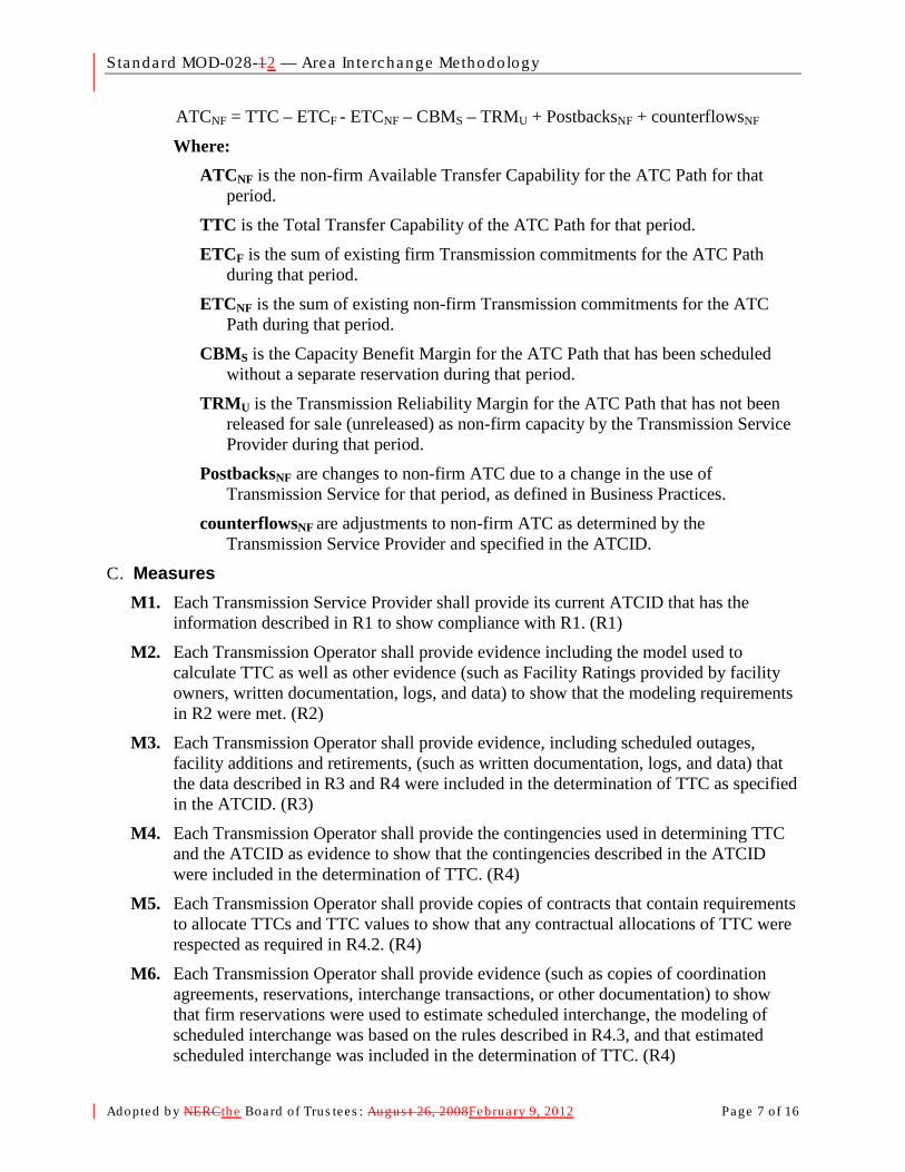
Standard MOD-028-12 — Area In te rchange Methodology
Adopted b y NERCthe Board of Trus tees : Augus t 26, 2008February 9, 2012 Page 7 o f 16
ATCNF = TTC – ETCF - ETCNF – CBMS – TRMU + PostbacksNF + counterflowsNF
Where: ATCNF is the non-firm Available Transfer Capability for the ATC Path for that
period.
TTC is the Total Transfer Capability of the ATC Path for that period.
ETCF is the sum of existing firm Transmission commitments for the ATC Path during that period.
ETCNF is the sum of existing non-firm Transmission commitments for the ATC Path during that period.
CBMS is the Capacity Benefit Margin for the ATC Path that has been scheduled without a separate reservation during that period.
TRMU is the Transmission Reliability Margin for the ATC Path that has not been released for sale (unreleased) as non-firm capacity by the Transmission Service Provider during that period.
PostbacksNF are changes to non-firm ATC due to a change in the use of Transmission Service for that period, as defined in Business Practices.
counterflowsNF are adjustments to non-firm ATC as determined by the Transmission Service Provider and specified in the ATCID.
C. Measures M1. Each Transmission Service Provider shall provide its current ATCID that has the
information described in R1 to show compliance with R1. (R1)
M2. Each Transmission Operator shall provide evidence including the model used to calculate TTC as well as other evidence (such as Facility Ratings provided by facility owners, written documentation, logs, and data) to show that the modeling requirements in R2 were met. (R2)
M3. Each Transmission Operator shall provide evidence, including scheduled outages, facility additions and retirements, (such as written documentation, logs, and data) that the data described in R3 and R4 were included in the determination of TTC as specified in the ATCID. (R3)
M4. Each Transmission Operator shall provide the contingencies used in determining TTC and the ATCID as evidence to show that the contingencies described in the ATCID were included in the determination of TTC. (R4)
M5. Each Transmission Operator shall provide copies of contracts that contain requirements to allocate TTCs and TTC values to show that any contractual allocations of TTC were respected as required in R4.2. (R4)
M6. Each Transmission Operator shall provide evidence (such as copies of coordination agreements, reservations, interchange transactions, or other documentation) to show that firm reservations were used to estimate scheduled interchange, the modeling of scheduled interchange was based on the rules described in R4.3, and that estimated scheduled interchange was included in the determination of TTC. (R4)
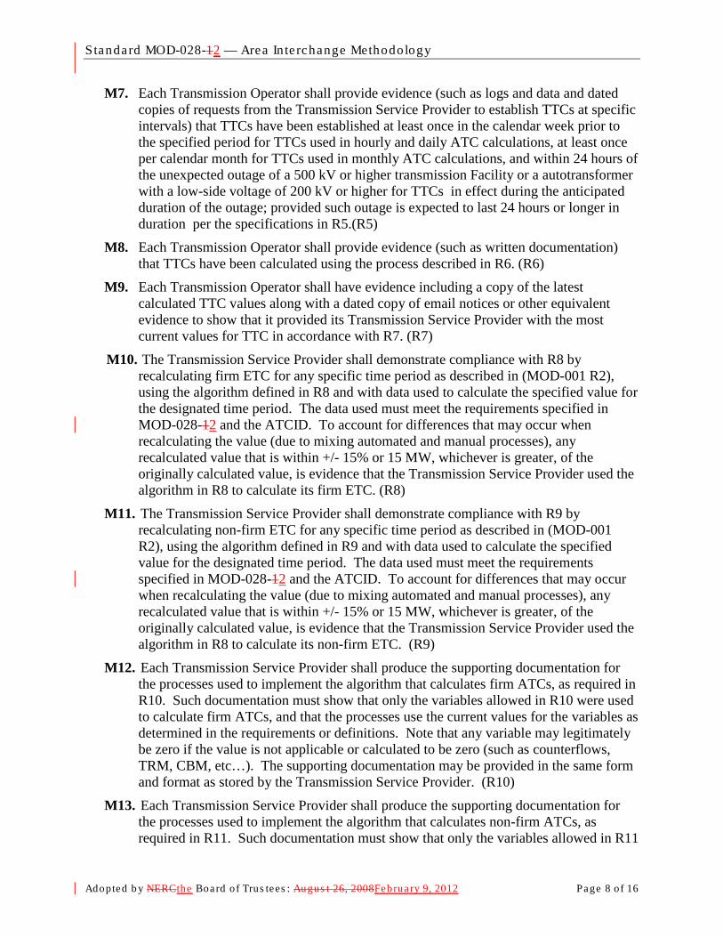
Standard MOD-028-12 — Area In te rchange Methodology
Adopted b y NERCthe Board of Trus tees : Augus t 26, 2008February 9, 2012 Page 8 o f 16
M7. Each Transmission Operator shall provide evidence (such as logs and data and dated copies of requests from the Transmission Service Provider to establish TTCs at specific intervals) that TTCs have been established at least once in the calendar week prior to the specified period for TTCs used in hourly and daily ATC calculations, at least once per calendar month for TTCs used in monthly ATC calculations, and within 24 hours of the unexpected outage of a 500 kV or higher transmission Facility or a autotransformer with a low-side voltage of 200 kV or higher for TTCs in effect during the anticipated duration of the outage; provided such outage is expected to last 24 hours or longer in duration per the specifications in R5.(R5)
M8. Each Transmission Operator shall provide evidence (such as written documentation) that TTCs have been calculated using the process described in R6. (R6)
M9. Each Transmission Operator shall have evidence including a copy of the latest calculated TTC values along with a dated copy of email notices or other equivalent evidence to show that it provided its Transmission Service Provider with the most current values for TTC in accordance with R7. (R7)
M10. The Transmission Service Provider shall demonstrate compliance with R8 by recalculating firm ETC
M11. The Transmission Service Provider shall demonstrate compliance with R9 by recalculating non-firm ETC for any specific time period as described in (MOD-001 R2), using the algorithm defined in R9 and with data used to calculate the specified value for the designated time period. The data used must meet the requirements specified in MOD-028-12 and the ATCID. To account for differences that may occur when recalculating the value (due to mixing automated and manual processes), any recalculated value that is within +/- 15% or 15 MW, whichever is greater, of the originally calculated value, is evidence that the Transmission Service Provider used the algorithm in R8 to calculate its non-firm ETC. (R9)
for any specific time period as described in (MOD-001 R2), using the algorithm defined in R8 and with data used to calculate the specified value for the designated time period. The data used must meet the requirements specified in MOD-028-12 and the ATCID. To account for differences that may occur when recalculating the value (due to mixing automated and manual processes), any recalculated value that is within +/- 15% or 15 MW, whichever is greater, of the originally calculated value, is evidence that the Transmission Service Provider used the algorithm in R8 to calculate its firm ETC. (R8)
M12. Each Transmission Service Provider shall produce the supporting documentation for the processes used to implement the algorithm that calculates firm ATCs, as required in R10. Such documentation must show that only the variables allowed in R10 were used to calculate firm ATCs, and that the processes use the current values for the variables as determined in the requirements or definitions. Note that any variable may legitimately be zero if the value is not applicable or calculated to be zero (such as counterflows, TRM, CBM, etc…). The supporting documentation may be provided in the same form and format as stored by the Transmission Service Provider. (R10)
M13. Each Transmission Service Provider shall produce the supporting documentation for the processes used to implement the algorithm that calculates non-firm ATCs, as required in R11. Such documentation must show that only the variables allowed in R11

Standard MOD-028-12 — Area In te rchange Methodology
Adopted b y NERCthe Board of Trus tees : Augus t 26, 2008February 9, 2012 Page 9 o f 16
were used to calculate non-firm ATCs, and that the processes use the current values for the variables as determined in the requirements or definitions. Note that any variable may legitimately be zero if the value is not applicable or calculated to be zero (such as counterflows, TRM, CBM, etc…). The supporting documentation may be provided in the same form and format as stored by the Transmission Service Provider. (R11)
D. Compliance 1. Compliance Monitoring Process
1.1. Compliance Enforcement Authority For entities that do not work for the Regional Entity.
1.2. , the Regional Entity shall serve as the Compliance Monitoring Period and ResetEnforcement Authority.
Not applicable. For functional entities that work for their Regional Entity, the ERO or a Regional Entity approved by the ERO and FERC or other applicable governmental authorities shall serve as the Compliance Enforcement Authority.
1.3.1.2. Data Retention
The following evidence retention periods identify the period of time an entity is required to retain specific evidence to demonstrate compliance. For instances where the evidence retention period specified below is shorter than the time since the last audit, the Compliance Enforcement Authority may ask an entity to provide other evidence to show that it was compliant for the full time period since the last audit.
The Transmission Operator and Transmission Service Provider shall keep data or evidence to show compliance as identified below unless directed by its Compliance Enforcement Authority to retain specific evidence for a longer period of time as part of an investigation:
- The Transmission Service Provider shall retain its current, in force ATCID and any prior versions of the ATCID that were in force since the last compliance audit to show compliance with R1.
- The Transmission Operator shall have its latest model used to calculate TTC and evidence of the previous version to show compliance with R2.
- The Transmission Operator shall retain evidence to show compliance with R3 for the most recent 12 months or until the model used to calculate TTC is updated, whichever is longer.
- The Transmission Operator shall retain evidence to show compliance with R4, R5, R6 and R7 for the most recent 12 months.
- The Transmission Service Provider shall retain evidence to show compliance in calculating hourly values required in R8 and R9 for the most recent 14 days; evidence to show compliance in calculating daily values required in R8 and R9 for the most recent 30 days; and evidence to show compliance in calculating monthly values required in R8 and R9 for the most recent 60 days.

Standard MOD-028-12 — Area In te rchange Methodology
Adopted b y NERCthe Board of Trus tees : Augus t 26, 2008February 9, 2012 Page 10 of 16
- The Transmission Service Provider shall retain evidence to show compliance with R10 and R11 for the most recent 12 months.
- If a Transmission Service Provider or Transmission Operator is found non-compliant, it shall keep information related to the non-compliance until found compliant.
- The Compliance Enforcement Authority shall keep the last audit records and all requested and submitted subsequent audit records.
1.4.1.3. Compliance Monitoring and Enforcement Processes: The following processes may be used:
- Compliance Audits
- Self-Certifications
- Spot Checking
- Compliance Violation Investigations
- Self-Reporting
- Complaints
1.5.1.4. Additional Compliance Information None.
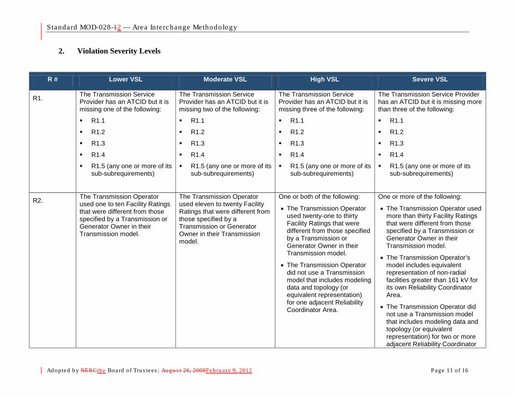
Standard MOD-028-12 — Area In te rchange Methodology
Adopted b y NERCthe Board of Trus tees : Augus t 26, 2008February 9, 2012 Page 11 of 16
2. Violation Severity Levels
R # Lower VSL Moderate VSL High VSL Severe VSL
R1. The Transmission Service Provider has an ATCID but it is missing one of the following:
R1.1
R1.2
R1.3
R1.4
R1.5 (any one or more of its sub-subrequirements)
The Transmission Service Provider has an ATCID but it is missing two of the following:
R1.1
R1.2
R1.3
R1.4
R1.5 (any one or more of its sub-subrequirements)
The Transmission Service Provider has an ATCID but it is missing three of the following:
R1.1
R1.2
R1.3
R1.4
R1.5 (any one or more of its sub-subrequirements)
The Transmission Service Provider has an ATCID but it is missing more than three of the following:
R1.1
R1.2
R1.3
R1.4
R1.5 (any one or more of its sub-subrequirements)
R2. The Transmission Operator used one to ten Facility Ratings that were different from those specified by a Transmission or Generator Owner in their Transmission model.
The Transmission Operator used eleven to twenty Facility Ratings that were different from those specified by a Transmission or Generator Owner in their Transmission model.
One or both of the following:
• The Transmission Operator used twenty-one to thirty Facility Ratings that were different from those specified by a Transmission or Generator Owner in their Transmission model.
• The Transmission Operator did not use a Transmission model that includes modeling data and topology (or equivalent representation) for one adjacent Reliability Coordinator Area.
One or more of the following:
• The Transmission Operator used more than thirty Facility Ratings that were different from those specified by a Transmission or Generator Owner in their Transmission model.
• The Transmission Operator’s model includes equivalent representation of non-radial facilities greater than 161 kV for its own Reliability Coordinator Area.
• The Transmission Operator did not use a Transmission model that includes modeling data and topology (or equivalent representation) for two or more adjacent Reliability Coordinator
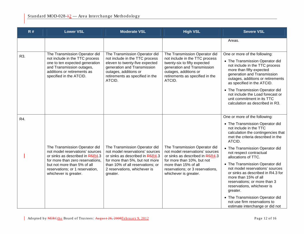
Standard MOD-028-12 — Area In te rchange Methodology
Adopted b y NERCthe Board of Trus tees : Augus t 26, 2008February 9, 2012 Page 12 of 16
R # Lower VSL Moderate VSL High VSL Severe VSL
Areas.
R3. The Transmission Operator did not include in the TTC process one to ten expected generation and Transmission outages, additions or retirements as specified in the ATCID.
The Transmission Operator did not include in the TTC process eleven to twenty-five expected generation and Transmission outages, additions or retirements as specified in the ATCID.
The Transmission Operator did not include in the TTC process twenty-six to fifty expected generation and Transmission outages, additions or retirements as specified in the ATCID.
One or more of the following:
• The Transmission Operator did not include in the TTC process more than fifty expected generation and Transmission outages, additions or retirements as specified in the ATCID.
• The Transmission Operator did not include the Load forecast or unit commitment in its TTC calculation as described in R3.
R4.
The Transmission Operator did not model reservations’ sources or sinks as described in R5R4.3 for more than zero reservations, but not more than 5% of all reservations; or 1 reservation, whichever is greater.
The Transmission Operator did not model reservations’ sources or sinks as described in R5R4.3 for more than 5%, but not more than 10% of all reservations; or 2 reservations, whichever is greater.
The Transmission Operator did not model reservations’ sources or sinks as described in R5R4.3 for more than 10%, but not more than 15% of all reservations; or 3 reservations, whichever is greater.
One or more of the following:
• The Transmission Operator did not include in the TTC calculation the contingencies that met the criteria described in the ATCID.
• The Transmission Operator did not respect contractual allocations of TTC.
• The Transmission Operator did not model reservations’ sources or sinks as described in R4.3 for more than 15% of all reservations; or more than 3 reservations, whichever is greater.
• The Transmission Operator did not use firm reservations to estimate interchange or did not

Standard MOD-028-12 — Area In te rchange Methodology
Adopted b y NERCthe Board of Trus tees : Augus t 26, 2008February 9, 2012 Page 13 of 16
R # Lower VSL Moderate VSL High VSL Severe VSL
utilize that estimate in the TTC calculation as described in R4.3.
R5. One or more of the following:
• The Transmission Operator did not establish TTCs for use in hourly or daily ATCs within 7 calendar days but did establish the values within 10 calendar days
• The Transmission Operator did not establish TTCs for use in monthly ATCs during a calendar month but did establish the values within the next consecutive calendar month
One or more of the following:
• The Transmission Operator did not establish TTCs for use in hourly or daily ATCs in 10 calendar days but did establish the values within 13 calendar days
• The Transmission Operator did not establish TTCs for use in monthly ATCs during a two consecutive calendar month period but did establish the values within the third consecutive calendar month
One or more of the following:
• The Transmission Operator did not establish TTCs for used in hourly or daily ATCs in 13 calendar days but did establish the values within 16 calendar days
• The Transmission Operator did not establish TTCs for use in monthly ATCs during a three consecutive calendar month period but did establish the values within the fourth consecutive calendar month
One or more of the following:
• The Transmission Operator did not establish TTCs for used in hourly or daily ATCs in 16 calendar days
• The Transmission Operator did not establish TTCs for use in monthly ATCs during a four or more consecutive calendar month period
• The Transmission Operator did not establish TTCs within 24 hrs of the triggers defined in R5.3
R6. N/A N/A N/A
The Transmission Operator did not calculate TTCs per the process specified in R6.
R7. One or more of the following:
• The Transmission Operator provided its Transmission Service Provider with its ATC Path TTCs used in hourly or daily ATC calculations more than one calendar day after their determination, but not been more than two calendar days after their determination.
• The Transmission Operator
One or more of the following:
• The Transmission Operator provided its Transmission Service Provider with its ATC Path TTCs used in hourly or daily ATC calculations more than two calendar days after their determination, but not been more than three calendar days after their determination.
• The Transmission Operator
One or more of the following:
• The Transmission Operator provided its Transmission Service Provider with its ATC Path TTCs used in hourly or daily ATC calculations more than three calendar days after their determination, but not been more than four calendar days after their determination.
• The Transmission Operator
One or more of the following:
• The Transmission Operator provided its Transmission Service Provider with its ATC Path TTCs used in hourly or daily ATC calculations more than four calendar days after their determination.
• The Transmission Operator did not provide its Transmission Service Provider with its ATC Path TTCs used in hourly or

Standard MOD-028-12 — Area In te rchange Methodology
Adopted b y NERCthe Board of Trus tees : Augus t 26, 2008February 9, 2012 Page 14 of 16
R # Lower VSL Moderate VSL High VSL Severe VSL
has not provided its Transmission Service Provider with its ATC Path TTCs used in monthly ATC calculations more than seven calendar days after their determination, but not more than 14 calendar days since their determination.
has not provided its Transmission Service Provider with its ATC Path TTCs used in monthly ATC calculations more than 14 calendar days after their determination, but not been more than 21 calendar days after their determination.
has not provided its Transmission Service Provider with its ATC Path TTCs used in monthly ATC calculations more than 21 calendar days after their determination, but not been more than 28 calendar days after their determination.
daily ATC calculations.
• The Transmission Operator provided its Transmission Service Provider with its ATC Path TTCs used in monthly ATC calculations more than 28 calendar days after their determination.
• The Transmission Operator did not provide its Transmission Service Provider with its ATC Path TTCs used in monthly ATC calculations.
R8. For a specified period, the Transmission Service Provider calculated a firm ETC with an absolute value different than that calculated in M10 for the same period, and the absolute value difference was more than 15% of the value calculated in the measure or 15MW, whichever is greater, but not more than 25% of the value calculated in the measure or 25MW, whichever is greater.
For a specified period, the Transmission Service Provider calculated a firm ETC with an absolute value different than that calculated in M10 for the same period, and the absolute value difference was more than 25% of the value calculated in the measure or 25MW, whichever is greater, but not more than 35% of the value calculated in the measure or 35MW, whichever is greater.
For a specified period, the Transmission Service Provider calculated a firm ETC with an absolute value different than that calculated in M10 for the same period, and the absolute value difference was more than 35% of the value calculated in the measure or 35MW, whichever is greater, but not more than 45% of the value calculated in the measure or 45MW, whichever is greater.
For a specified period, the Transmission Service Provider calculated a firm ETC with an absolute value different than that calculated in M10 for the same period, and the absolute value difference was more than 45% of the value calculated in the measure or 45MW, whichever is greater.
R9. For a specified period, the Transmission Service Provider calculated a non-firm ETC with an absolute value different than that calculated in M11 for the same period, and the absolute value difference was more than 15% of the value calculated in the measure or 15MW, whichever is greater, but not
For a specified period, the Transmission Service Provider calculated a non-firm ETC with an absolute value different than that calculated in M11 for the same period, and the absolute value difference was more than 25% of the value calculated in the measure or 25MW, whichever is greater, but not
For a specified period, the Transmission Service Provider calculated a non-firm ETC with an absolute value different than that calculated in M11 for the same period, and the absolute value difference was more than 35% of the value calculated in the measure or 35MW, whichever is greater, but not
For a specified period, the Transmission Service Provider calculated a non-firm ETC with an absolute value different than that calculated in M11 for the same period, and the absolute value difference was more than 45% of the value calculated in the measure or 45MW, whichever is greater.
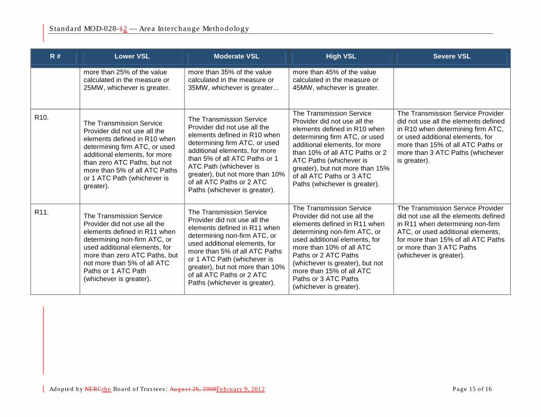
Standard MOD-028-12 — Area In te rchange Methodology
Adopted b y NERCthe Board of Trus tees : Augus t 26, 2008February 9, 2012 Page 15 of 16
R # Lower VSL Moderate VSL High VSL Severe VSL
more than 25% of the value calculated in the measure or 25MW, whichever is greater.
more than 35% of the value calculated in the measure or 35MW, whichever is greater...
more than 45% of the value calculated in the measure or 45MW, whichever is greater.
R10. The Transmission Service Provider did not use all the elements defined in R10 when determining firm ATC, or used additional elements, for more than zero ATC Paths, but not more than 5% of all ATC Paths or 1 ATC Path (whichever is greater).
The Transmission Service Provider did not use all the elements defined in R10 when determining firm ATC, or used additional elements, for more than 5% of all ATC Paths or 1 ATC Path (whichever is greater), but not more than 10% of all ATC Paths or 2 ATC Paths (whichever is greater).
The Transmission Service Provider did not use all the elements defined in R10 when determining firm ATC, or used additional elements, for more than 10% of all ATC Paths or 2 ATC Paths (whichever is greater), but not more than 15% of all ATC Paths or 3 ATC Paths (whichever is greater).
The Transmission Service Provider did not use all the elements defined in R10 when determining firm ATC, or used additional elements, for more than 15% of all ATC Paths or more than 3 ATC Paths (whichever is greater).
R11. The Transmission Service Provider did not use all the elements defined in R11 when determining non-firm ATC, or used additional elements, for more than zero ATC Paths, but not more than 5% of all ATC Paths or 1 ATC Path (whichever is greater).
The Transmission Service Provider did not use all the elements defined in R11 when determining non-firm ATC, or used additional elements, for more than 5% of all ATC Paths or 1 ATC Path (whichever is greater), but not more than 10% of all ATC Paths or 2 ATC Paths (whichever is greater).
The Transmission Service Provider did not use all the elements defined in R11 when determining non-firm ATC, or used additional elements, for more than 10% of all ATC Paths or 2 ATC Paths (whichever is greater), but not more than 15% of all ATC Paths or 3 ATC Paths (whichever is greater).
The Transmission Service Provider did not use all the elements defined in R11 when determining non-firm ATC, or used additional elements, for more than 15% of all ATC Paths or more than 3 ATC Paths (whichever is greater).

Standard MOD-028-12 — Area In te rchange Methodology
Adopted b y NERCthe Board of Trus tees : Augus t 26, 2008February 9, 2012 Page 16 of 16
Version History Version Date Action Change Tracking
1 August 26, 2008 Adopted by the Board of Trustees
2 February 9, 2012 Adopted by the Board of Trustees

Exhibit C
Implementation Plan for Reliability Standard submitted for Approval

Implementation Plan Project 2011-INT-01 Approvals Requested MOD-028-2 – Area Interchange Methodology Prerequisite Approvals None
Effective Date New or Revised Standards MOD-028-2—In those jurisdictions where regulatory approval is required, this standard shall become effective on the first day of the first calendar quarter after applicable regulatory approval. In those jurisdictions where no regulatory approval is required, this standard shall become effective on the first day of the first calendar quarter after Board of Trustees approval. Standards for Retirement MOD-028-1—Midnight of the day immediately prior to the Effective Date of MOD-028-2 in the particular Jurisdiction in which the new standard is becoming effective.

Exhibit D
Consideration of Comments

Consideration of Comments Project 2011-INT-01 – Interpretation of MOD-028 R3.1 for FPL The 2011-INT-01 – Interpretation Drafting Team thanks all commenters who submitted comments on the SAR and draft MOD-028-2 standard (Area Interchange Methodology). These standards were posted for a 45-day public comment period from October 3, 2011 through November 16, 2011. Stakeholders were asked to provide feedback on the standards and associated documents through a special electronic comment form. There were 9 sets of comments, including comments from 51 different people from approximately 43 companies representing all of the 10 Industry Segments as shown in the table on the following pages. Ballots indicated general support with a quorum of 88.05% and an affirmative vote of 85.53%. Summary Consideration: Most comments indicated the use of a “Rapid” approach to clarify the standard is acceptable. Some comments expressed concern regarding the updates to the compliance sections of the standard. These changes were administrative in nature and do not indicate changes to the stakeholder-approved requirements of the standard.
The majority of the comments received indicate the issue raised in the interpretation request has been satisfactorily resolved.
Two comments questioned if the intent of the standard was to go beyond the changes written, and to require an hourly load forecast for use in an hourly TTC and a daily load forecast for use in a daily TTC. The intent of the standard is to allow for either daily or hourly load forecasts in the specified situation. In other words, a “daily” load forecast is the minimum acceptable performance, but an “hourly” forecast is also acceptable to meet the requirement.
Specifically, some commenters questioned the data retention section of the standard and how it should be applied. Data should be retained as stated in the original standard. The added language gives instruction for when the retention period is shorter than the time since the last audit. According to Section 3.1.4.2 of Appendix 4c to NERC’s Rules of Procedure, an entity is responsible for compliance for the entire time since the last audit and will be expected to demonstrate its compliance. The paragraph that was added to the Data Retention section of the standard was written by NERC Legal staff to notify entities of this responsibility and is not specific to MOD-028-2; this paragraph is being added to all standards as they are revised.
One commenter identified a capitalization error in R3.1, which has been corrected as noted so that the term “daily” is not capitalized. Additionally, the capitalization of the word “monthly” was removed, and a formatting error corrected. No other changes were made to the standard.

2011-INT-01 MOD-028 Consideration of Comments 2
All comments submitted may be reviewed in their original format on the standard’s project page:
http://www.nerc.com/filez/standards/2011-INT-01_Interpretation_MOD-028-1_FPL.html
If you feel that your comment has been overlooked, please let us know immediately. Our goal is to give every comment serious consideration in this process! If you feel there has been an error or omission, you can contact the Vice President and Director of Standards, Herb Schrayshuen, at 404-446-2560 or at [email protected]. In addition, there is a NERC Reliability Standards Appeals Process.1
1 The appeals process is in the Reliability Standards Development Procedures: http://www.nerc.com/standards/newstandardsprocess.html.

2011-INT-01 MOD-028 Consideration of Comments 3
Index to Questions, Comments, and Responses
1. Do you agree with the use of this “Rapid” approach to clarify the standard, rather than clarifying the standard through an Interpretation? If No, please explain your concerns ............................ 7
2. Does the language in the SAR adequately represent the issue raised in the interpretation request?
If No, please provide your suggestions to modify the SAR. ..................................................... 9 3. Does the proposed revision resolve the issue raised in the interpretation request? If No, please
provide your suggestions to modify the standard. ............................................................... 10 4. If you have any other comments on the SAR or on the proposed Standard that you have not
provided above, please provide them here. ....................................................................... 14

2011-INT-01 MOD-028 Consideration of Comments 4
The Industry Segments are: 1 — Transmission Owners 2 — RTOs, ISOs 3 — Load-serving Entities 4 — Transmission-dependent Utilities 5 — Electric Generators 6 — Electricity Brokers, Aggregators, and Marketers 7 — Large Electricity End Users 8 — Small Electricity End Users 9 — Federal, State, Provincial Regulatory or other Government Entities 10 — Regional Reliability Organizations, Regional Entities
Group/Individual Commenter Organization Registered Ballot Body Segment
1 2 3 4 5 6 7 8 9 10
1. Group Guy Zito Northeast Power Coordinating Council X Additional Member Additional Organization Region Segment Selection
1. Alan Adamson New York State Reliability Council, LLC NPCC 10 2. Greg Campoli New York Independent System Operator NPCC 2 3. Sylvain Clermont Hydro-Quebec TransEnergie NPCC 1 4. Chris de Graffenried Consolidate Edison Co. of New York, Inc. NPCC 1 5. Gerry Dunbar Northeast Power Coordinating Council NPCC 10 6. Brian Evans-Mongeon Utility Services NPCC 8 7. Mike Garton Dominion Resources Services, Inc. NPCC 5 8. Kathleen Goodman ISO - New England NPCC 2

2011-INT-01 MOD-028 Consideration of Comments 5
Group/Individual Commenter Organization Registered Ballot Body Segment
1 2 3 4 5 6 7 8 9 10
9. Chantel Haswell FPL Group, Inc. NPCC 5 10. David Kiguel Hydro One Networks Inc. NPCC 1 11. Michael R. Lombardi Northeast Utilities NPCC 1 12. Randy MacDonald New Brunswick Power Transmission NPCC 9 13. Bruce Metruck New York Power Authority NPCC 6 14. Lee Pedowicz Northeast Power Coordinating Council NPCC 10 15. Robert Pellegrini The United Illuminating Company NPCC 1 16. Si-Truc Phan Hydro-Quebec TransEnergie NPCC 1 17. David Ramkalawan Ontario Power Generation, Inc. NPCC 5 18. Saurabh Saksena National Grid NPCC 1 19. Michael Schiavone National Grid NPCC 1 20. Wayne Sipperly New York Power Authority NPCC 5 21. Tina Teng Independent Electricty System Operator NPCC 2 22. Donald Weaver New Brunswick System Operator NPCC 2 23. Ben Wu Orange and Rockland Utilities NPCC 1 24. Peter Yost Consolidated Edison Co. of New York, Inc. NPCC 3
2. Group James R. Manning NCEMC Reps X X X X X No additional members listed. 3.
Group Jason L. Marshall ACES Power Marketing Standards Collaborators X
Additional Member Additional Organization Region Segment Selection 1. James Jones AEPCO/SWTC WECC 1, 5
4. Group Will Smith MRO NSRF X X X X X X X X X Additional Member Additional Organization Region Segment Selection
1. Mahmood Safi OPPD MRO 1, 3, 5, 6 2. Chuck Lawerence ATC MRO 1 3. Tom Webb WPS MRO 3, 4, 5, 6 4. Jodi Jenson WAPA MRO 1, 6 5. Ken Goldsmith ALTW MRO 4 6. Alice Ireland XCEL/NSP MRO 1, 3, 5, 6 7. Dave Rudolph BEPC MRO 1, 3, 5, 6

2011-INT-01 MOD-028 Consideration of Comments 6
Group/Individual Commenter Organization Registered Ballot Body Segment
1 2 3 4 5 6 7 8 9 10
8. Eric Ruskamp LES MRO 1, 3, 5, 6 9. Joe DePoorter MGE MRO 3, 4, 5, 6 10. Scott Nickels RPU MRO 4 11. Terry Harbour MEC MRO 1, 3, 5, 6 12. Marie Knox MISO MRO 2 13. Lee Kittelson OTP MRO 1, 3, 4, 5 14. Scott Bos MPW MRO 1, 3, 5, 6 15. Tony Eddleman NPPD MRO 1, 3, 5 16. Mike Brytowski GRE MRO 1, 3, 5, 6 17. Richard Burt MPC MRO 1, 3, 5, 6
5. Individual Anthony Jablonski ReliabilityFirst X 6. Individual Greg Rowland Duke Energy X X X X 7. Individual Ross Kovacs Georgia Transmission Corporation X 8. Individual Joe Petaski Manitoba Hydro X X X X 9.
Individual
Annie Lauterbach/Laura Trolese Bonneville Power Administration X X X X
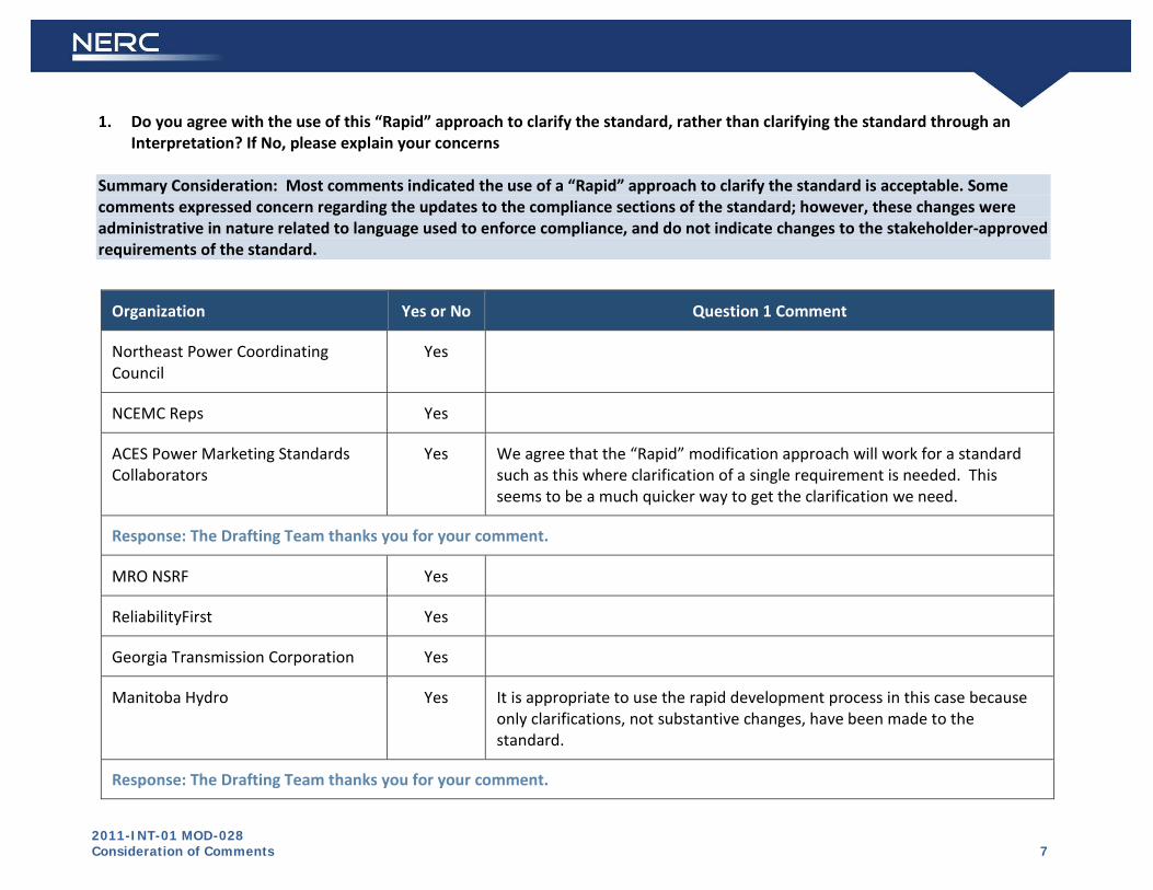
2011-INT-01 MOD-028 Consideration of Comments 7
1.
Do you agree with the use of this “Rapid” approach to clarify the standard, rather than clarifying the standard through an Interpretation? If No, please explain your concerns
Summary Consideration: Most comments indicated the use of a “Rapid” approach to clarify the standard is acceptable. Some comments expressed concern regarding the updates to the compliance sections of the standard; however, these changes were administrative in nature related to language used to enforce compliance, and do not indicate changes to the stakeholder-approved requirements of the standard.
Organization Yes or No Question 1 Comment
Northeast Power Coordinating Council
Yes
NCEMC Reps Yes
ACES Power Marketing Standards Collaborators
Yes We agree that the “Rapid” modification approach will work for a standard such as this where clarification of a single requirement is needed. This seems to be a much quicker way to get the clarification we need.
Response: The Drafting Team thanks you for your comment.
MRO NSRF Yes
ReliabilityFirst Yes
Georgia Transmission Corporation Yes
Manitoba Hydro Yes It is appropriate to use the rapid development process in this case because only clarifications, not substantive changes, have been made to the standard.
Response: The Drafting Team thanks you for your comment.

2011-INT-01 MOD-028 Consideration of Comments 8
Organization Yes or No Question 1 Comment
Duke Energy No The Rapid approach method would have been sufficient had the response been limited to only the request for clarification. This revision goes beyond the scope of the original request for clarification by modifying the VRFs as well as the Compliance Enforcement and Data Retention portions of Section D. While these additional changes may simply be conforming changes to match a new Standards pro-forma template, they should be addressed and explained along with the other provided background information.
Response: The Drafting Team thanks you for your comment. The indication of “Pending” for the VRFs is intended to indicate that the VRFs are not approved by FERC. The VRFs were not filed with the original filing, and were addressed separately due to NERC staff concerns they did not comply with NERC’s VRF guidelines. Staff proposed VRFs were posted for industry comment January 7, 2009 through January 28, 2009. Staff made changes based on stakeholder feedback, and those VRFs were presented to and approved by the NERC Board of Trustees on November 4, 2010. The VRFs were filed with the Commission on December 1, 2010; FERC has not yet acted on them.
The other changes were administrative in nature related to language used to enforce compliance, and do not indicate changes to the stakeholder-approved requirements of the standard.
Bonneville Power Administration
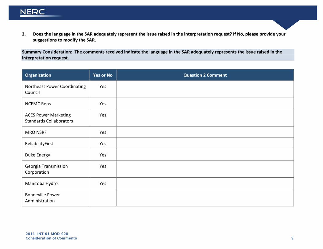
2011-INT-01 MOD-028 Consideration of Comments 9
2.
Does the language in the SAR adequately represent the issue raised in the interpretation request? If No, please provide your suggestions to modify the SAR.
Summary Consideration: The comments received indicate the language in the SAR adequately represents the issue raised in the interpretation request.
Organization Yes or No Question 2 Comment
Northeast Power Coordinating Council
Yes
NCEMC Reps Yes
ACES Power Marketing Standards Collaborators
Yes
MRO NSRF Yes
ReliabilityFirst Yes
Duke Energy Yes
Georgia Transmission Corporation
Yes
Manitoba Hydro Yes
Bonneville Power Administration

2011-INT-01 MOD-028 Consideration of Comments 10
3. Does the proposed revision resolve the issue raised in the interpretation request? If No, please provide your suggestions to modify the standard.
Summary Consideration: The majority of the comments received indicate the issue has been satisfactorily resolved. Some comments expressed concern regarding the updates to the compliance sections of the standard; however, these changes were administrative in nature related to language used to enforce compliance, and do not indicate changes to the stakeholder-approved requirements of the standard.
Two comments questioned if the intent of the standard was to go beyond the changes written, and to require an hourly load forecast for use in an hourly TTC and a daily load forecast for use in a daily TTC. This is not the intent of the standard. The intent of the standard is to allow for either daily or hourly load forecasts in the specified situation.
Organization Yes or No Question 3 Comment
Duke Energy Yes We are OK with the changes made to Requirement 3, but, in the interest of full disclosure, we expect that some explanatory language should be included to address the changes made not related to the FPL Request for Interpretation.
Response: The Drafting Team thanks you for your comment. The indication of “Pending” for the VRFs is intended to indicate that the VRFs are not approved by FERC. The VRFs were not filed with the original filing, and were addressed separately due to NERC staff concerns they did not comply with NERC’s VRF guidelines. Staff proposed VRFs were posted for industry comment January 7, 2009 through January 28, 2009. Staff made changes based on stakeholder feedback, and those VRFs were presented to and approved by the NERC Board of Trustees on November 4, 2010. The VRFs were filed with the Commission on December 1, 2010; FERC has not yet acted on them.
The other changes were administrative in nature related to language used to enforce compliance, and do not indicate changes to the stakeholder-approved requirements of the standard.
Northeast Power Coordinating Council
Yes
MRO NSRF Yes

2011-INT-01 MOD-028 Consideration of Comments 11
Organization Yes or No Question 3 Comment
ReliabilityFirst Yes
Manitoba Hydro Yes
Southwest Transmission Cooperative, Inc.
Negative We agree that the “Rapid” modification approach will work for a standard such as this where clarification of a single requirement is needed. This seems to be a much quicker way to get the clarification we need. The proposed changes do not appear to solve the original ambiguity. Because 3.1.2 describes using “A daily or hourly load forecast for TTCs used in current-day and next-day ATC calculations”, a registered entity might still believe that it has to calculate hourly TTCs. A clarification is needed that hourly load forecasts are required if the TOP uses hourly TTCs and daily load forecasts are needed if the TOP calculates a single TTC for a day.
Response: The Drafting Team thanks you for your comment. The standard is not intended to require an hourly load forecast for hourly TTCs. Rather, it is intended to indicate that entities may use daily OR hourly forecasts in the TTC calculation for TTCs used in the current-day and next-day time frames. In other words, a daily load forecast is the minimum, but entities may also use hourly if they so choose.
ACES Power Marketing Negative We do not think the issue has been fully addressed. Please see our formal comments.
Response: The Drafting Team thanks you for your comment.
ACES Power Marketing Standards Collaborators and NCEMC Reps
No The proposed changes do not appear to solve the original ambiguity. Because 3.1.2 describes using “A daily or hourly load forecast for TTCs used in current-day and next-day ATC calculations”, a registered entity might still believe that it has to calculate hourly TTCs. A clarification is needed that hourly load forecasts are required if the TOP uses hourly TTCs and daily load forecasts are needed if the TOP calculates a single TTC for a day.
Response: The Drafting Team thanks you for your comment. The standard is not intended to require an hourly load forecast for hourly TTCs. Rather, it is intended to indicate that entities may use daily OR hourly forecasts in the TTC calculation for TTCs used
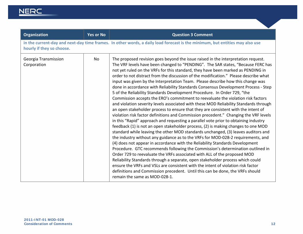
2011-INT-01 MOD-028 Consideration of Comments 12
Organization Yes or No Question 3 Comment
in the current-day and next-day time frames. In other words, a daily load forecast is the minimum, but entities may also use hourly if they so choose.
Georgia Transmission Corporation
No The proposed revision goes beyond the issue raised in the interpretation request. The VRF levels have been changed to “PENDING”. The SAR states, “Because FERC has not yet ruled on the VRFs for this standard, they have been marked as PENDING in order to not distract from the discussion of the modification.” Please describe what input was given by the Interpretation Team. Please describe how this change was done in accordance with Reliability Standards Consensus Development Process - Step 5 of the Reliability Standards Development Procedure. In Order 729, “the Commission accepts the ERO’s commitment to reevaluate the violation risk factors and violation severity levels associated with these MOD Reliability Standards through an open stakeholder process to ensure that they are consistent with the intent of violation risk factor definitions and Commission precedent.” Changing the VRF levels in this “Rapid” approach and requesting a parallel vote prior to obtaining industry feedback (1) is not an open stakeholder process, (2) is making changes to one MOD standard while leaving the other MOD standards unchanged, (3) leaves auditors and the industry without any guidance as to the VRFs for MOD-028-2 requirements, and (4) does not appear in accordance with the Reliability Standards Development Procedure. GTC recommends following the Commission’s determination outlined in Order 729 to reevaluate the VRFs associated with ALL of the proposed MOD Reliability Standards through a separate, open stakeholder process which could ensure the VRFs and VSLs are consistent with the intent of violation risk factor definitions and Commission precedent. Until this can be done, the VRFs should remain the same as MOD-028-1.
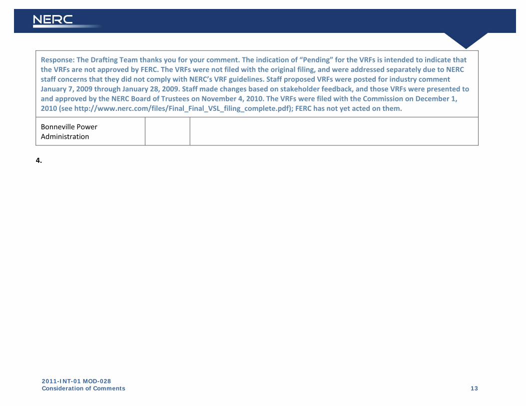
2011-INT-01 MOD-028 Consideration of Comments 13
Response: The Drafting Team thanks you for your comment. The indication of “Pending” for the VRFs is intended to indicate that the VRFs are not approved by FERC. The VRFs were not filed with the original filing, and were addressed separately due to NERC staff concerns that they did not comply with NERC’s VRF guidelines. Staff proposed VRFs were posted for industry comment January 7, 2009 through January 28, 2009. Staff made changes based on stakeholder feedback, and those VRFs were presented to and approved by the NERC Board of Trustees on November 4, 2010. The VRFs were filed with the Commission on December 1, 2010 (see http://www.nerc.com/files/Final_Final_VSL_filing_complete.pdf); FERC has not yet acted on them.
Bonneville Power Administration
4.
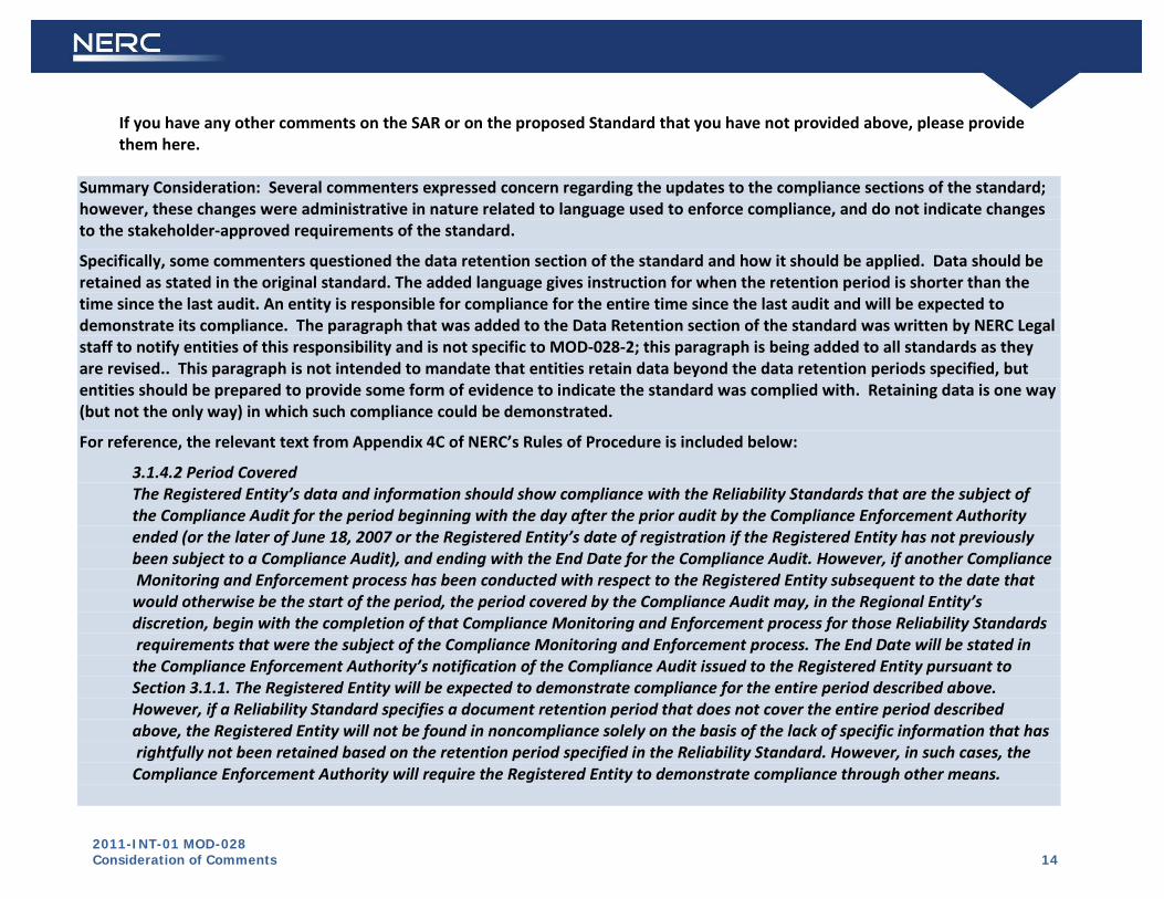
2011-INT-01 MOD-028 Consideration of Comments 14
If you have any other comments on the SAR or on the proposed Standard that you have not provided above, please provide them here.
Summary Consideration: Several commenters expressed concern regarding the updates to the compliance sections of the standard; however, these changes were administrative in nature related to language used to enforce compliance, and do not indicate changes to the stakeholder-approved requirements of the standard.
Specifically, some commenters questioned the data retention section of the standard and how it should be applied. Data should be retained as stated in the original standard. The added language gives instruction for when the retention period is shorter than the time since the last audit. An entity is responsible for compliance for the entire time since the last audit and will be expected to demonstrate its compliance. The paragraph that was added to the Data Retention section of the standard was written by NERC Legal staff to notify entities of this responsibility and is not specific to MOD-028-2; this paragraph is being added to all standards as they are revised.. This paragraph is not intended to mandate that entities retain data beyond the data retention periods specified, but entities should be prepared to provide some form of evidence to indicate the standard was complied with. Retaining data is one way (but not the only way) in which such compliance could be demonstrated.
For reference, the relevant text from Appendix 4C of NERC’s Rules of Procedure is included below:
3.1.4.2 Period Covered The Registered Entity’s data and information should show compliance with the Reliability Standards that are the subject of the Compliance Audit for the period beginning with the day after the prior audit by the Compliance Enforcement Authority ended (or the later of June 18, 2007 or the Registered Entity’s date of registration if the Registered Entity has not previously been subject to a Compliance Audit), and ending with the End Date for the Compliance Audit. However, if another Compliance Monitoring and Enforcement process has been conducted with respect to the Registered Entity subsequent to the date that would otherwise be the start of the period, the period covered by the Compliance Audit may, in the Regional Entity’s discretion, begin with the completion of that Compliance Monitoring and Enforcement process for those Reliability Standards requirements that were the subject of the Compliance Monitoring and Enforcement process. The End Date will be stated in the Compliance Enforcement Authority’s notification of the Compliance Audit issued to the Registered Entity pursuant to Section 3.1.1. The Registered Entity will be expected to demonstrate compliance for the entire period described above. However, if a Reliability Standard specifies a document retention period that does not cover the entire period described above, the Registered Entity will not be found in noncompliance solely on the basis of the lack of specific information that has rightfully not been retained based on the retention period specified in the Reliability Standard. However, in such cases, the Compliance Enforcement Authority will require the Registered Entity to demonstrate compliance through other means.

2011-INT-01 MOD-028 Consideration of Comments 15
One commenter identified a capitalization error in R3.1, which has been corrected as noted so that the term “daily” is not capitalized.
Organization Yes or No Question 4 Comment
Northern Indiana Public Service Co.
Abstain In MISO, not covered by this standard
Response: The Drafting Team thanks you for your comment.
Keys Energy Services Affirmative Although the added language in the Data Retention section of the standard reflects the current language in the Rules of Procedure, it is unwise to have to change standards on a Rules of Procedure change, e.g., if the Rules of Procedure language on data retention is changed, would all the standards that mirrored that language also need to be changed and resubmitted to FERC for approval? This is too burdensome. The added wording should be stricken. Another possible solution is to refer to the section of the Rules of Procedure in the standard such that if a change to the RoP occurs, the standard would not need to be changed. This would require that the section numbering of the RoP remain consistent to not cause a change in the standard, but, such a numbering change is less likely to occur than a change in the wording.
Response: The Drafting Team thanks you for your comment. The changes to which you refer are administrative in nature related to language used to enforce compliance, and do not indicate changes to the stakeholder-approved requirements of the standard.
Data should be retained as stated in the original standard. The added language gives instruction for when the retention period is shorter than the time since the last audit. An entity is responsible for compliance for the entire time since the last audit and will be expected to demonstrate its compliance. The paragraph that was added to the Data Retention section of the standard was written by NERC Legal staff to notify entities of this responsibility and is not specific to MOD-028-2; this paragraph is being added to all standards as they are revised.. This is not intended to mandate that entities retain data beyond the data retention periods specified, but entities should be prepared to provide some form of evidence to indicate the standard was complied with. Retaining data is one way (but not the only way) in which such compliance could be demonstrated.

2011-INT-01 MOD-028 Consideration of Comments 16
Organization Yes or No Question 4 Comment
Florida Municipal Power Agency
Affirmative Although the added language in the Data Retention section of the standard reflects the current language in the Rules of Procedure, FMPA believes it is unwise to have to change standards on a Rules of Procedure change, e.g., if the Rules of Procedure language on data retention is changed, would all the standards that mirrored that language also need to be changed and resubmitted to FERC for approval? FMPA believes this is too burdensome. The added wording should be stricken. Another possible solution is to refer to the section of the Rules of Procedure in the standard such that if a change to the RoP occurs, the standard would not need to be changed. This would require that the section numbering of the RoP remain consistent to not cause a change in the standard, but, such a numbering change is less likely to occur than a change in the wording.
Response: The Drafting Team thanks you for your comment. The changes to which you refer are administrative in nature related to language used to enforce compliance, and do not indicate changes to the stakeholder-approved requirements of the standard.
An entity is responsible for compliance for the entire time since the last audit and will be expected to demonstrate its compliance. The paragraph that was added to the Data Retention section of the standard was written by NERC Legal staff to notify entities of this responsibility and is not specific to MOD-028-2; this paragraph is being added to all standards as they are revised.. The added language gives instruction for when the retention period is shorter than the time since the last audit. An entity may be asked to show compliance for the entire time since the last audit. This is not intended to mandate that entities retain data beyond the data retention periods specified, but entities should be prepared to provide some form of evidence to indicate the standard was complied with. Retaining data is one way (but not the only way) in which such compliance could be demonstrated.
Your suggestion to refer to the section of the Rules of Procedures is inconsistent with the current guidance to drafting teams, but will be submitted to NERC Legal for consideration for future drafting efforts.
Cleco Power LLC Negative Reference section 1.2 NERC should be clearer about what data time frames they wish for us to retain data. If they want us to retain all data or other supporting data since the last audit, they should just say "all data since the last audit should be retained."
Response: The Drafting Team thanks you for your comment. The changes to which you refer are administrative in nature related to

2011-INT-01 MOD-028 Consideration of Comments 17
Organization Yes or No Question 4 Comment
language used to enforce compliance, and do not indicate changes to the stakeholder-approved requirements of the standard.
Data should be retained as stated in the original standard. The added language gives instruction for when the retention period is shorter than the time since the last audit. An entity is responsible for compliance for the entire time since the last audit and will be expected to demonstrate its compliance. The paragraph that was added to the Data Retention section of the standard was written by NERC Legal staff to notify entities of this responsibility and is not specific to MOD-028-2; this paragraph is being added to all standards as they are revised.. This is not intended to mandate that entities retain data beyond the data retention periods specified, but entities should be prepared to provide some form of evidence to indicate the standard was complied with. Retaining data is one way (but not the only way) in which such compliance could be demonstrated.
Gainesville Regional Utilities Negative I am OK with the changes in R3 to consolidate the two time frames which are sensible and consistent with the intent of the original standard. But, the changes under section D1.1 are not within the scope of the SAR and were not part of the interpretation request. The changes under Section D1.2 were not part of the SAR or interpretation request and are inconsistent with the original standard drafted by the technical experts, and approved by the industry. I understand that the standards team was aware of the amount of data potentially involved with the different requirements, set specific time lines to allow for verification of compliance with the standard without creating an undue burden in terms of data management, storage and recovery. The Team and the Industry in approving the standard felt that those time frames were appropriate, and that not every piece of data - some of which changes multiple times in an hour - need to be retained for three plus years. Ideally the SAR team would reconsider this change and return to the time frames originally determined by the drafting team and industry. At a minimum however the SAR team should allow 180 days after regulatory approval since multiple applications provided by various third party vendors may need to be modified to accommodate this change. The Team should also clarify that this expanded evidence requirement applies from the effective date of MOD 028-2 and beyond since MOD 028-1 did not require this longer term retention and data may already have been deleted.
Response: The Drafting Team thanks you for your comment. The changes to which you refer are administrative in nature related to

2011-INT-01 MOD-028 Consideration of Comments 18
Organization Yes or No Question 4 Comment
language used to enforce compliance, and do not indicate changes to the stakeholder-approved requirements of the standard.
Data should be retained as stated in the original standard. The added language gives instruction for when the retention period is shorter than the time since the last audit. An entity is responsible for compliance for the entire time since the last audit and will be expected to demonstrate its compliance. The paragraph that was added to the Data Retention section of the standard was written by NERC Legal staff to notify entities of this responsibility and is not specific to MOD-028-2; this paragraph is being added to all standards as they are revised.. This is not intended to mandate that entities retain data beyond the data retention periods specified, but entities should be prepared to provide some form of evidence to indicate the standard was complied with. Retaining data is one way (but not the only way) in which such compliance could be demonstrated.
Georgia Transmission Corporation
Negative The proposed revision goes beyond FP&L’s request for interpretation. The VRF levels have been changed to “PENDING”. The SAR states, “Because FERC has not yet ruled on the VRFs for this standard, they have been marked as PENDING in order to not distract from the discussion of the modification.” Please describe what input was given by the Interpretation Team. Please describe how this change was done in accordance with Reliability Standards Consensus Development Process - Step 5 of the Reliability Standards Development Procedure. In Order 729, “the Commission accepts the ERO’s commitment to reevaluate the violation risk factors and violation severity levels associated with these MOD Reliability Standards through an open stakeholder process to ensure that they are consistent with the intent of violation risk factor definitions and Commission precedent.” Changing the VRF levels in this “Rapid” approach and requesting a parallel vote prior to obtaining industry feedback (1) is not an open stakeholder process, (2) is making changes to one MOD standard while leaving the other MOD standards unchanged, (3) leaves auditors and the industry without any guidance as to the VRFs for MOD-028-2 requirements, and (4) does not appear in accordance with the Reliability Standards Development Procedure. GTC recommends following the Commission’s determination outlined in Order 729 to reevaluate the VRF associated with ALL of the proposed MOD Reliability Standards through a separate, open stakeholder process which could ensure the VRFs and VSLs are consistent with the intent of violation risk factor definitions and Commission precedent.

2011-INT-01 MOD-028 Consideration of Comments 19
Organization Yes or No Question 4 Comment
Response: The Drafting Team thanks you for your comment. The indication of “Pending” for the VRFs is intended to indicate that the VRFs are not approved by FERC. The VRFs were not filed with the original filing, and were addressed separately due to NERC staff concerns that they did not comply with NERC’s VRF guidelines. Staff proposed VRFs were posted for industry comment January 7, 2009 through January 28, 2009. Staff made changes based on stakeholder feedback, and those VRFs were presented to and approved by the NERC Board of Trustees on November 4, 2010. The VRFs were filed with the Commission on December 1, 2010 (http://www.nerc.com/files/Final_Final_VSL_filing_complete.pdf); FERC has not yet acted on them.
Lakeland Electric Negative While the clarification provided is acceptable, the standard was also unacceptably modified to add increased data retention requirements as discussed in NERC Compliance Process Bulletin #2011-001. As the general rules governing data are subject to change they should not be placed within standards, especially when they seem to increase the data retention requirements beyond the SDT's original intent. Note that if the general rule changes - the standard will still have this additional data retention requirement and this is unacceptable.
Response: The Drafting Team thanks you for your comment. The changes to which you refer are administrative in nature related to language used to enforce compliance, and do not indicate changes to the stakeholder-approved requirements of the standard.
Data should be retained as stated in the original standard. The added language gives instruction for when the retention period is shorter than the time since the last audit. An entity is responsible for compliance for the entire time since the last audit and will be expected to demonstrate its compliance. The paragraph that was added to the Data Retention section of the standard was written by NERC Legal staff to notify entities of this responsibility and is not specific to MOD-028-2; this paragraph is being added to all standards as they are revised. This is not intended to mandate that entities retain data beyond the data retention periods specified, but entities should be prepared to provide some form of evidence to indicate the standard was complied with. Retaining data is one way (but not the only way) in which such compliance could be demonstrated.
Orlando Utilities Commission Negative The changes under Section D1.2 were not part of the SAR or interpretation request and are inconsistent with the original standard drafted by the technical experts, and approved by the industry. The standards team was aware of the amount of data potentially involved with the different requirements, and set specific storage limits to allow for verification of compliance with the standard without creating an undue

2011-INT-01 MOD-028 Consideration of Comments 20
Organization Yes or No Question 4 Comment
burden in terms of data management, storage and recovery. As written this revised version effectively set’s aside the time limits set by the drafting team and would require every piece of data to be indexed and retained for three years.
Response: The Drafting Team thanks you for your comment. The changes to which you refer are administrative in nature related to language used to enforce compliance, and do not indicate changes to the stakeholder-approved requirements of the standard.
Data should be retained as stated in the original standard. The added language gives instruction for when the retention period is shorter than the time since the last audit. An entity is responsible for compliance for the entire time since the last audit and will be expected to demonstrate its compliance. The paragraph that was added to the Data Retention section of the standard was written by NERC Legal staff to notify entities of this responsibility and is not specific to MOD-028-2; this paragraph is being added to all standards as they are revised. This is not intended to mandate that entities retain data beyond the data retention periods specified, but entities should be prepared to provide some form of evidence to indicate the standard was complied with. Retaining data is one way (but not the only way) in which such compliance could be demonstrated.
Seminole Electric Cooperative, Inc.
Negative The reason for voting against this is the insertion of language in section D.1.2. (Compliance, Data Retention) which is unreasonably broad and imposes new and immediate evidence requirements. Significant modifications to systems will likely be required to meet these requirements.
Response: The Drafting Team thanks you for your comment. The changes to which you refer are administrative in nature related to language used to enforce compliance, and do not indicate changes to the stakeholder-approved requirements of the standard.
Data should be retained as stated in the original standard. The added language gives instruction for when the retention period is shorter than the time since the last audit. An entity is responsible for compliance for the entire time since the last audit and will be expected to demonstrate its compliance. The paragraph that was added to the Data Retention section of the standard was written by NERC Legal staff to notify entities of this responsibility and is not specific to MOD-028-2; this paragraph is being added to all standards as they are revised. This is not intended to mandate entities retain data beyond the data retention periods specified, but entities should be prepared to provide some form of evidence to indicate the standard was complied with. Retaining the data is one way (but not the only way) in which such compliance could be demonstrated.
Cleco Power | Cleco Power Negative Reference section 1.2 NERC should be clearer about what data time frames they wish
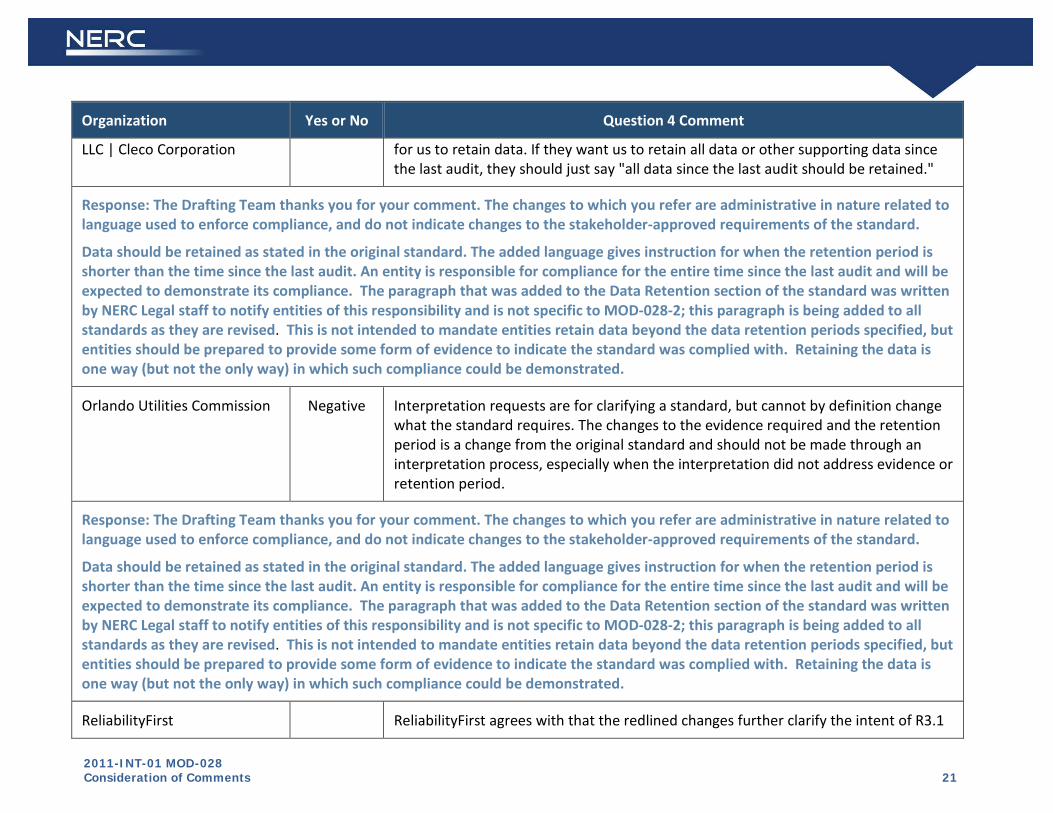
2011-INT-01 MOD-028 Consideration of Comments 21
Organization Yes or No Question 4 Comment
LLC | Cleco Corporation for us to retain data. If they want us to retain all data or other supporting data since the last audit, they should just say "all data since the last audit should be retained."
Response: The Drafting Team thanks you for your comment. The changes to which you refer are administrative in nature related to language used to enforce compliance, and do not indicate changes to the stakeholder-approved requirements of the standard.
Data should be retained as stated in the original standard. The added language gives instruction for when the retention period is shorter than the time since the last audit. An entity is responsible for compliance for the entire time since the last audit and will be expected to demonstrate its compliance. The paragraph that was added to the Data Retention section of the standard was written by NERC Legal staff to notify entities of this responsibility and is not specific to MOD-028-2; this paragraph is being added to all standards as they are revised. This is not intended to mandate entities retain data beyond the data retention periods specified, but entities should be prepared to provide some form of evidence to indicate the standard was complied with. Retaining the data is one way (but not the only way) in which such compliance could be demonstrated.
Orlando Utilities Commission Negative Interpretation requests are for clarifying a standard, but cannot by definition change what the standard requires. The changes to the evidence required and the retention period is a change from the original standard and should not be made through an interpretation process, especially when the interpretation did not address evidence or retention period.
Response: The Drafting Team thanks you for your comment. The changes to which you refer are administrative in nature related to language used to enforce compliance, and do not indicate changes to the stakeholder-approved requirements of the standard.
Data should be retained as stated in the original standard. The added language gives instruction for when the retention period is shorter than the time since the last audit. An entity is responsible for compliance for the entire time since the last audit and will be expected to demonstrate its compliance. The paragraph that was added to the Data Retention section of the standard was written by NERC Legal staff to notify entities of this responsibility and is not specific to MOD-028-2; this paragraph is being added to all standards as they are revised. This is not intended to mandate entities retain data beyond the data retention periods specified, but entities should be prepared to provide some form of evidence to indicate the standard was complied with. Retaining the data is one way (but not the only way) in which such compliance could be demonstrated.
ReliabilityFirst ReliabilityFirst agrees with that the redlined changes further clarify the intent of R3.1

2011-INT-01 MOD-028 Consideration of Comments 22
Organization Yes or No Question 4 Comment
but noticed one typo. The term “Daily” in part 3.1.3 should not be capitalized since the term “Daily” is not a definition listed in the NERC Glossary of terms.
Response: The Drafting Team thanks you for your comment. R3.1 has been corrected as noted so that the term “daily” is not capitalized.
Northeast Power Coordinating Council
NCEMC Reps
ACES Power Marketing Standards Collaborators
MRO NSRF NONE
Duke Energy
Georgia Transmission Corporation
Manitoba Hydro
Bonneville Power Administration
BPA has no comments or concerns at this time as BPA does not implement this standard.
END OF REPORT

Exhibit E
Record of Development of Proposed Reliability Standard

Project 2011-INT-01
Revision of MOD-028-1 to address FPL Request for Interpretation
Related Files
Status: The standard and implementation plan were adopted by the Board of Trustees on February 9. 2012. Background: In May 2011, FPL requested an interpretation of MOD-028-1, Requirement R3.1. The requests asks for clarification of the timing and frequency of TTC calculations needed for ATC calculations. At its July 2011 meeting the Standards Committee approved addressing FPL’s request for interpretation through a rapid revision to the MOD-028-1 standard. The interpretation drafting team was appointed as the standard drafting team and directed to submit both a SAR and proposed revisions to MOD-028-1 addressing the issue raised in the RFI. Because the revisions are narrowly focused on addressing the clarification requested by FPL, the Standards Committee approved waiving the initial 30-day formal comment period and directed that the SAR and proposed revisions to the standard be posted for a 45-day parallel comment period and ballot.
Draft Action Dates Results Consideration of
Comments
Draft 2 MOD-028-2 Clean(13) Redline Last Approved(14) | Last Posted(15) Implementation Plan(16) Supporting Materials:
Recirculation Ballot
Info(19)
Vote>>
12/12/11 - 12/22/11 (closed)
Summary(20)
Full Record(21)
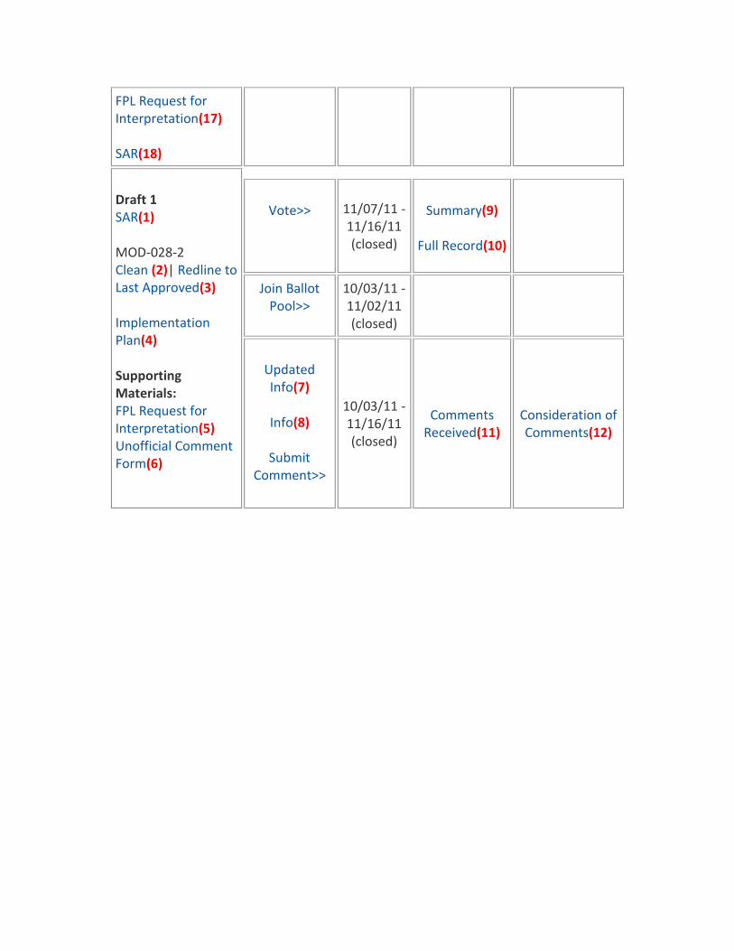
FPL Request for Interpretation(17) SAR(18)
Draft 1 SAR(1) MOD-028-2 Clean (2)| Redline to Last Approved(3) Implementation Plan(4) Supporting Materials: FPL Request for Interpretation(5) Unofficial Comment Form(6)
Vote>> 11/07/11 - 11/16/11 (closed)
Summary(9)
Full Record(10)
Join Ballot Pool>>
10/03/11 - 11/02/11 (closed)
Updated Info(7)
Info(8)
Submit
Comment>>
10/03/11 - 11/16/11 (closed)
Comments Received(11)
Consideration of Comments(12)
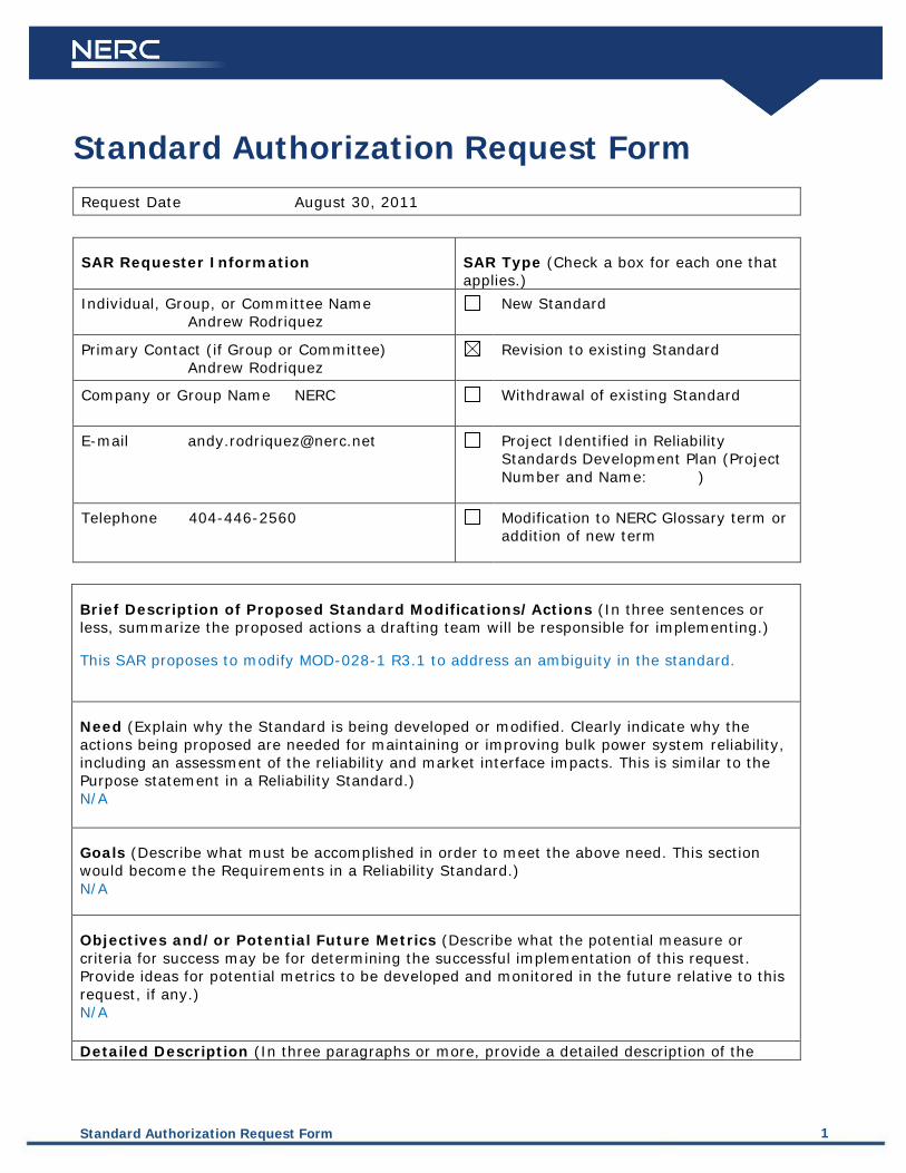
Standard Authorization Request Form 1
Standard Authorization Request Form
Request Date August 30, 2011
SAR Requester Information SAR Type (Check a box for each one that applies.)
Individual, Group, or Committee Name Andrew Rodriquez
New Standard
Primary Contact (if Group or Committee) Andrew Rodriquez
Revision to existing Standard
Company or Group Name NERC Withdrawal of existing Standard
E-mail [email protected] Project Identified in Reliability Standards Development Plan (Project Number and Name: )
Telephone 404-446-2560 Modification to NERC Glossary term or addition of new term
Brief Description of Proposed Standard Modifications/Actions (In three sentences or less, summarize the proposed actions a drafting team will be responsible for implementing.)
This SAR proposes to modify MOD-028-1 R3.1 to address an ambiguity in the standard.
Need (Explain why the Standard is being developed or modified. Clearly indicate why the actions being proposed are needed for maintaining or improving bulk power system reliability, including an assessment of the reliability and market interface impacts. This is similar to the Purpose statement in a Reliability Standard.) N/A
Goals (Describe what must be accomplished in order to meet the above need. This section would become the Requirements in a Reliability Standard.) N/A
Objectives and/or Potential Future Metrics (Describe what the potential measure or criteria for success may be for determining the successful implementation of this request. Provide ideas for potential metrics to be developed and monitored in the future relative to this request, if any.) N/A Detailed Description (In three paragraphs or more, provide a detailed description of the
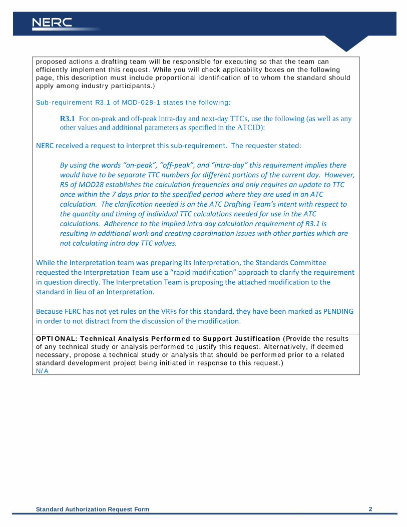
Standard Authorization Request Form 2
proposed actions a drafting team will be responsible for executing so that the team can efficiently implement this request. While you will check applicability boxes on the following page, this description must include proportional identification of to whom the standard should apply among industry participants.) Sub-requirement R3.1 of MOD-028-1 states the following:
R3.1 For on-peak and off-peak intra-day and next-day TTCs, use the following (as well as any other values and additional parameters as specified in the ATCID):
NERC received a request to interpret this sub-requirement. The requester stated:
By using the words “on-peak”, “off-peak”, and “intra-day” this requirement implies there would have to be separate TTC numbers for different portions of the current day. However, R5 of MOD28 establishes the calculation frequencies and only requires an update to TTC once within the 7 days prior to the specified period where they are used in an ATC calculation. The clarification needed is on the ATC Drafting Team’s intent with respect to the quantity and timing of individual TTC calculations needed for use in the ATC calculations. Adherence to the implied intra day calculation requirement of R3.1 is resulting in additional work and creating coordination issues with other parties which are not calculating intra day TTC values.
While the Interpretation team was preparing its Interpretation, the Standards Committee requested the Interpretation Team use a “rapid modification” approach to clarify the requirement in question directly. The Interpretation Team is proposing the attached modification to the standard in lieu of an Interpretation. Because FERC has not yet rules on the VRFs for this standard, they have been marked as PENDING in order to not distract from the discussion of the modification. OPTIONAL: Technical Analysis Performed to Support Justification (Provide the results of any technical study or analysis performed to justify this request. Alternatively, if deemed necessary, propose a technical study or analysis that should be performed prior to a related standard development project being initiated in response to this request.) N/A
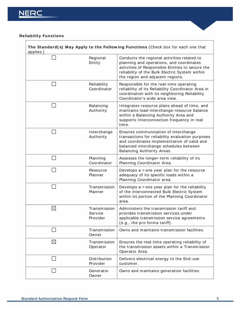
Standard Authorization Request Form 3
Reliability Functions
The Standard(s) May Apply to the Following Functions (Check box for each one that applies.)
Conducts the regional activities related to planning and operations, and coordinates activities of Responsible Entities to secure the reliability of the Bulk Electric System within the region and adjacent regions.
Regional Entity
Responsible for the real-time operating reliability of its Reliability Coordinator Area in coordination with its neighboring Reliability Coordinator’s wide area view.
Reliability Coordinator
Balancing Authority
Integrates resource plans ahead of time, and maintains load-interchange-resource balance within a Balancing Authority Area and supports Interconnection frequency in real time.
Interchange Authority
Ensures communication of interchange transactions for reliability evaluation purposes and coordinates implementation of valid and balanced interchange schedules between Balancing Authority Areas.
Planning Coordinator
Assesses the longer-term reliability of its Planning Coordinator Area.
Resource Planner
Develops a >one year plan for the resource adequacy of its specific loads within a Planning Coordinator area.
Transmission Planner
Develops a >one year plan for the reliability of the interconnected Bulk Electric System within its portion of the Planning Coordinator area.
Transmission Service Provider
Administers the transmission tariff and provides transmission services under applicable transmission service agreements (e.g., the pro forma tariff).
Transmission Owner
Owns and maintains transmission facilities.
Transmission Operator
Ensures the real-time operating reliability of the transmission assets within a Transmission Operator Area.
Distribution Provider
Delivers electrical energy to the End-use customer.
Generator Owner
Owns and maintains generation facilities.
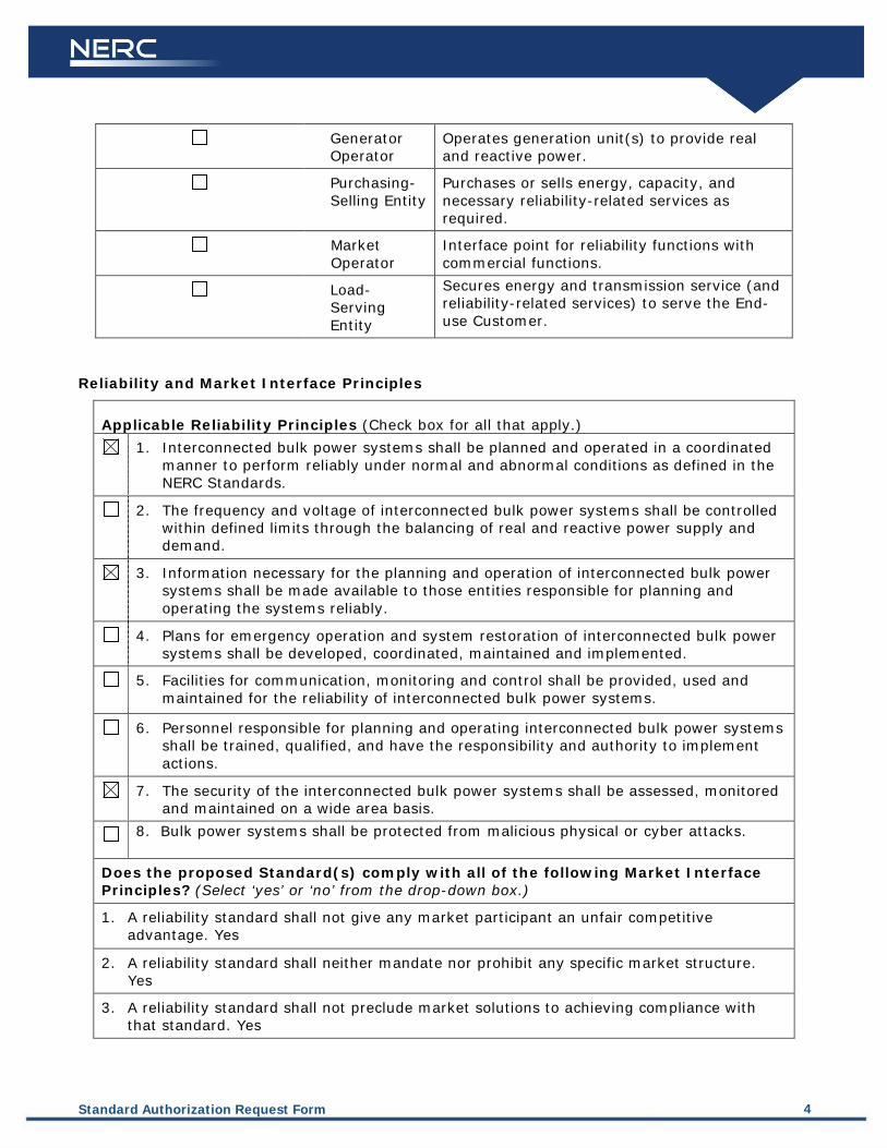
Standard Authorization Request Form 4
Generator Operator
Operates generation unit(s) to provide real and reactive power.
Purchasing-Selling Entity
Purchases or sells energy, capacity, and necessary reliability-related services as required.
Market Operator
Interface point for reliability functions with commercial functions.
Secures energy and transmission service (and reliability-related services) to serve the End-use Customer.
Load-Serving Entity
Reliability and Market Interface Principles
Applicable Reliability Principles (Check box for all that apply.)
1.
Interconnected bulk power systems shall be planned and operated in a coordinated manner to perform reliably under normal and abnormal conditions as defined in the NERC Standards.
2.
The frequency and voltage of interconnected bulk power systems shall be controlled within defined limits through the balancing of real and reactive power supply and demand.
3.
Information necessary for the planning and operation of interconnected bulk power systems shall be made available to those entities responsible for planning and operating the systems reliably.
4.
Plans for emergency operation and system restoration of interconnected bulk power systems shall be developed, coordinated, maintained and implemented.
5.
Facilities for communication, monitoring and control shall be provided, used and maintained for the reliability of interconnected bulk power systems.
6.
Personnel responsible for planning and operating interconnected bulk power systems shall be trained, qualified, and have the responsibility and authority to implement actions.
7.
The security of the interconnected bulk power systems shall be assessed, monitored and maintained on a wide area basis.
8. Bulk power systems shall be protected from malicious physical or cyber attacks.
Does the proposed Standard(s) comply with all of the following Market Interface Principles?
1.
(Select ‘yes’ or ‘no’ from the drop-down box.)
2.
A reliability standard shall not give any market participant an unfair competitive advantage. Yes
3.
A reliability standard shall neither mandate nor prohibit any specific market structure. Yes
A reliability standard shall not preclude market solutions to achieving compliance with that standard. Yes

Standard Authorization Request Form 5
4.
A reliability standard shall not require the public disclosure of commercially sensitive information. All market participants shall have equal opportunity to access commercially non-sensitive information that is required for compliance with reliability standards. Yes
Related Standards
Standard No. Explanation
Related Projects
Project ID and Title Explanation
Regional Variances
Region Explanation
ERCOT
FRCC
MRO
NPCC
SERC
RFC
SPP
WECC
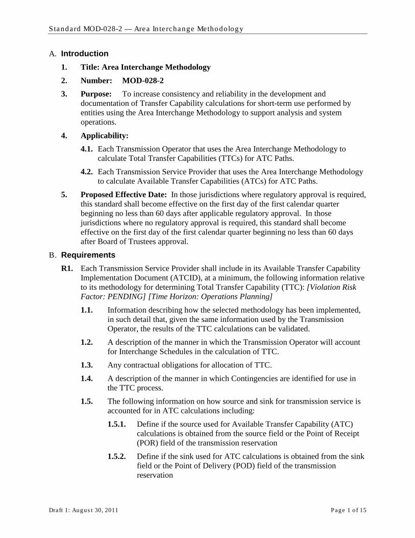
Standard MOD-028-2 — Area In te rchange Methodology
Draft 1: Augus t 30, 2011 Page 1 o f 15
A. Introduction 1. Title: Area Interchange Methodology 2. Number: MOD-028-2 3. Purpose: To increase consistency and reliability in the development and
documentation of Transfer Capability calculations for short-term use performed by entities using the Area Interchange Methodology to support analysis and system operations.
4. Applicability: 4.1. Each Transmission Operator that uses the Area Interchange Methodology to
calculate Total Transfer Capabilities (TTCs) for ATC Paths.
4.2. Each Transmission Service Provider that uses the Area Interchange Methodology to calculate Available Transfer Capabilities (ATCs) for ATC Paths.
5. Proposed Effective Date: In those jurisdictions where regulatory approval is required, this standard shall become effective on the first day of the first calendar quarter beginning no less than 60 days after applicable regulatory approval. In those jurisdictions where no regulatory approval is required, this standard shall become effective on the first day of the first calendar quarter beginning no less than 60 days after Board of Trustees approval.
B. Requirements R1. Each Transmission Service Provider shall include in its Available Transfer Capability
Implementation Document (ATCID), at a minimum, the following information relative to its methodology for determining Total Transfer Capability (TTC): [Violation Risk Factor: PENDING] [Time Horizon: Operations Planning] 1.1. Information describing how the selected methodology has been implemented,
in such detail that, given the same information used by the Transmission Operator, the results of the TTC calculations can be validated.
1.2. A description of the manner in which the Transmission Operator will account for Interchange Schedules in the calculation of TTC.
1.3. Any contractual obligations for allocation of TTC.
1.4. A description of the manner in which Contingencies are identified for use in the TTC process.
1.5. The following information on how source and sink for transmission service is accounted for in ATC calculations including:
1.5.1. Define if the source used for Available Transfer Capability (ATC) calculations is obtained from the source field or the Point of Receipt (POR) field of the transmission reservation
1.5.2. Define if the sink used for ATC calculations is obtained from the sink field or the Point of Delivery (POD) field of the transmission reservation

Standard MOD-028-2 — Area In te rchange Methodology
Draft 1: Augus t 30, 2011 Page 2 o f 15
1.5.3. The source/sink or POR/POD identification and mapping to the model.
1.5.4. If the Transmission Service Provider’s ATC calculation process involves a grouping of generation, the ATCID must identify how these generators participate in the group.
R2. When calculating TTC for ATC Paths, the Transmission Operator shall use a Transmission model that contains all of the following: [Violation Risk Factor: PENDING] [Time Horizon: Operations Planning] 2.1. Modeling data and topology of its Reliability Coordinator’s area of
responsibility. Equivalent representation of radial lines and facilities 161 kV or below is allowed.
2.2. Modeling data and topology (or equivalent representation) for immediately adjacent and beyond Reliability Coordination areas.
2.3. Facility Ratings specified by the Generator Owners and Transmission Owners.
R3. When calculating TTCs for ATC Paths, the Transmission Operator shall include the following data for the Transmission Service Provider’s area. The Transmission Operator shall also include the following data associated with Facilities that are explicitly represented in the Transmission model, as provided by adjacent Transmission Service Providers and any other Transmission Service Providers with which coordination agreements have been executed: [Violation Risk Factor: PENDING] [Time Horizon: Operations Planning]
3.1. For TTCs, use the following (as well as any other values and additional parameters as specified in the ATCID):
3.1.1. Expected generation and Transmission outages, additions, and retirements, included as specified in the ATCID.
3.1.2. A daily or hourly load forecast for TTCs used in current-day and next-day ATC calculations.
3.1.3. A Daily load forecast for TTCs used in ATC calculations for days two through 31.
3.1.4. A monthly load forecast for TTCs used in ATC calculations for months two through 13 months TTCs.
3.1.5. Unit commitment and dispatch order, to include all designated network resources and other resources that are committed or have the legal obligation to run, (within or out of economic dispatch) as they are expected to run.
R4. When calculating TTCs for ATC Paths, the Transmission Operator shall meet all of the following conditions: [Violation Risk Factor: PENDING] [Time Horizon: Operations Planning] 4.1. Use all Contingencies meeting the criteria described in the ATCID.
4.2. Respect any contractual allocations of TTC.

Standard MOD-028-2 — Area In te rchange Methodology
Draft 1: Augus t 30, 2011 Page 3 o f 15
4.3. Include, for each time period, the Firm Transmission Service expected to be scheduled as specified in the ATCID (filtered to reduce or eliminate duplicate impacts from transactions using Transmission service from multiple Transmission Service Providers) for the Transmission Service Provider, all adjacent Transmission Service Providers, and any Transmission Service Providers with which coordination agreements have been executed modeling the source and sink as follows:
- If the source, as specified in the ATCID, has been identified in the reservation and it is discretely modeled in the Transmission Service Provider’s Transmission model, use the discretely modeled point as the source.
- If the source, as specified in the ATCID, has been identified in the reservation and the point can be mapped to an “equivalence” or “aggregate representation” in the Transmission Service Provider’s Transmission model, use the modeled equivalence or aggregate as the source.
- If the source, as specified in the ATCID, has been identified in the reservation and the point cannot be mapped to a discretely modeled point, an “equivalence,” or an “aggregate representation” in the Transmission Service Provider’s Transmission model, use the immediately adjacent Balancing Authority associated with the Transmission Service Provider from which the power is to be received as the source.
- If the source, as specified in the ATCID, has not been identified in the reservation, use the immediately adjacent Balancing Authority associated with the Transmission Service Provider from which the power is to be received as the source.
- If the sink, as specified in the ATCID, has been identified in the reservation and it is discretely modeled in the Transmission Service Provider’s Transmission model, use the discretely modeled point shall as the sink.
- If the sink, as specified in the ATCID, has been identified in the reservation and the point can be mapped to an “equivalence” or “aggregate representation” in the Transmission Service Provider’s Transmission model, use the modeled equivalence or aggregate as the sink.
- If the sink, as specified in the ATCID, has been identified in the reservation and the point can not be mapped to a discretely modeled point, an “equivalence,” or an “aggregate representation” in the Transmission Service Provider’s Transmission model, use the immediately adjacent Balancing Authority associated with the Transmission Service Provider to which the power is to be delivered as the sink.
- If the sink, as specified in the ATCID, has not been identified in the reservation, use the immediately adjacent Balancing Authority associated with the Transmission Service Provider to which the power is being delivered as the sink.

Standard MOD-028-2 — Area In te rchange Methodology
Draft 1: Augus t 30, 2011 Page 4 o f 15
R5. Each Transmission Operator shall establish TTC for each ATC Path as defined below: [Violation Risk Factor: PENDING] [Time Horizon: Operations Planning] 5.1. At least once within the seven calendar days prior to the specified period for
TTCs used in hourly and daily ATC calculations.
5.2. At least once per calendar month for TTCs used in monthly ATC calculations.
5.3. Within 24 hours of the unexpected outage of a 500 kV or higher transmission Facility or a transformer with a low-side voltage of 200 kV or higher for TTCs in effect during the anticipated duration of the outage, provided such outage is expected to last 24 hours or longer.
R6. Each Transmission Operator shall establish TTC for each ATC Path using the following process: [Violation Risk Factor: PENDING] [Time Horizon: Operations Planning] 6.1. Determine the incremental Transfer Capability for each ATC Path by
increasing generation and/or decreasing load within the source Balancing Authority area and decreasing generation and/or increasing load within the sink Balancing Authority area until either:
- A System Operating Limit is reached on the Transmission Service Provider’s system, or
- A SOL is reached on any other adjacent system in the Transmission model that is not on the study path and the distribution factor is 5% or greater1
6.2. If the limit in step R6.1 can not be reached by adjusting any combination of load or generation, then set the incremental Transfer Capability by the results of the case where the maximum adjustments were applied.
.
6.3. Use (as the TTC) the lesser of:
− The sum of the incremental Transfer Capability and the impacts of Firm Transmission Services, as specified in the Transmission Service Provider’s ATCID, that were included in the study model, or
− The sum of Facility Ratings of all ties comprising the ATC Path.
6.4. For ATC Paths whose capacity uses jointly-owned or allocated Facilities, limit TTC for each Transmission Service Provider so the TTC does not exceed each Transmission Service Provider’s contractual rights.
R7. The Transmission Operator shall provide the Transmission Service Provider of that ATC Path with the most current value for TTC for that ATC Path no more than: [Violation Risk Factor: PENDING] [Time Horizon: Operations Planning]
7.1. One calendar day after its determination for TTCs used in hourly and daily ATC calculations.
7.2. Seven calendar days after its determination for TTCs used in monthly ATC calculations.
1 The Transmission operator may honor distribution factors less than 5% if desired.

Standard MOD-028-2 — Area In te rchange Methodology
Draft 1: Augus t 30, 2011 Page 5 o f 15
R8. When calculating Existing Transmission Commitments (ETCs) for firm commitments (ETCF
ETC
) for all time periods for an ATC Path the Transmission Service Provider shall use the following algorithm: [Violation Risk Factor: PENDING] [Time Horizon: Operations Planning]
F = NITSF + GFF + PTPF + RORF + OS
Where: F
NITSF is the firm capacity set aside for Network Integration Transmission Service (including the capacity used to serve bundled load within the Transmission Service Provider’s area with external sources) on ATC Paths that serve as interfaces with other Balancing Authorities.
GFF is the firm capacity set aside for Grandfathered Firm Transmission Service and contracts for energy and/or Transmission Service, where executed prior to the effective date of a Transmission Service Provider’s Open Access Transmission Tariff or safe harbor tariff on ATC Paths that serve as interfaces with other Balancing Authorities.
PTPF is the firm capacity reserved for confirmed Point-to-Point Transmission Service.
RORF is the capacity reserved for roll-over rights for Firm Transmission Service contracts granting Transmission Customers the right of first refusal to take or continue to take Transmission Service when the Transmission Customer’s Transmission Service contract expires or is eligible for renewal.
OSF is the firm capacity reserved for any other service(s), contract(s), or agreement(s) not specified above using Firm Transmission Service, including any other firm adjustments to reflect impacts from other ATC Paths of the Transmission Service Provider as specified in the ATCID.
R9. When calculating ETC for non-firm commitments (ETCNF
ETC
) for all time periods for an ATC Path the Transmission Service Provider shall use the following algorithm: [Violation Risk Factor: PENDING] [Time Horizon: Operations Planning]
NF = NITSNF + GFNF + PTPNF + OS
NF
Where: NITSNF is the non-firm capacity set aside for Network Integration Transmission
Service (i.e., secondary service , including the capacity used to serve bundled load within the Transmission Service Provider’s area with external sources) reserved on ATC Paths that serve as interfaces with other Balancing Authorities.
GFNF is the non-firm capacity reserved for Grandfathered Non-Firm Transmission Service and contracts for energy and/or Transmission Service, where executed prior to the effective date of a Transmission Service Provider’s Open Access Transmission Tariff or safe harbor tariff on ATC Paths that serve as interfaces with other Balancing Authorities.

Standard MOD-028-2 — Area In te rchange Methodology
Draft 1: Augus t 30, 2011 Page 6 o f 15
PTPNF is non-firm capacity reserved for confirmed Point-to-Point Transmission Service.
OSNF is the non-firm capacity reserved for any other service(s), contract(s), or agreement(s) not specified above using Non-Firm Transmission Service, including any other firm adjustments to reflect impacts from other ATC Paths of the Transmission Service Provider as specified in the ATCID.
R10. When calculating firm ATC for an ATC Path for a specified period, the Transmission Service Provider shall utilize the following algorithm: [Violation Risk Factor: PENDING] [Time Horizon: Operations Planning]
ATCF = TTC – ETCF – CBM – TRM + PostbacksF + counterflowsF
Where: ATCF is the firm Available Transfer Capability for the ATC Path for that period.
TTC is the Total Transfer Capability of the ATC Path for that period.
ETCF is the sum of existing firm Transmission commitments for the ATC Path during that period.
CBM is the Capacity Benefit Margin for the ATC Path during that period.
TRM is the Transmission Reliability Margin for the ATC Path during that period.
PostbacksF are changes to firm ATC due to a change in the use of Transmission Service for that period, as defined in Business Practices.
counterflowsF are adjustments to firm ATC as determined by the Transmission Service Provider and specified in the ATCID.
R11. When calculating non-firm ATC for a ATC Path for a specified period, the Transmission Service Provider shall use the following algorithm: [Violation Risk Factor: PENDING] [Time Horizon: Operations Planning] ATCNF = TTC – ETCF - ETCNF – CBMS – TRMU + PostbacksNF + counterflowsNF
Where: ATCNF is the non-firm Available Transfer Capability for the ATC Path for that
period.
TTC is the Total Transfer Capability of the ATC Path for that period.
ETCF is the sum of existing firm Transmission commitments for the ATC Path during that period.
ETCNF is the sum of existing non-firm Transmission commitments for the ATC Path during that period.
CBMS is the Capacity Benefit Margin for the ATC Path that has been scheduled without a separate reservation during that period.
TRMU is the Transmission Reliability Margin for the ATC Path that has not been released for sale (unreleased) as non-firm capacity by the Transmission Service Provider during that period.

Standard MOD-028-2 — Area In te rchange Methodology
Draft 1: Augus t 30, 2011 Page 7 o f 15
PostbacksNF are changes to non-firm ATC due to a change in the use of Transmission Service for that period, as defined in Business Practices.
counterflowsNF are adjustments to non-firm ATC as determined by the Transmission Service Provider and specified in the ATCID.
C. Measures M1. Each Transmission Service Provider shall provide its current ATCID that has the
information described in R1 to show compliance with R1. (R1)
M2. Each Transmission Operator shall provide evidence including the model used to calculate TTC as well as other evidence (such as Facility Ratings provided by facility owners, written documentation, logs, and data) to show that the modeling requirements in R2 were met. (R2)
M3. Each Transmission Operator shall provide evidence, including scheduled outages, facility additions and retirements, (such as written documentation, logs, and data) that the data described in R3 and R4 were included in the determination of TTC as specified in the ATCID. (R3)
M4. Each Transmission Operator shall provide the contingencies used in determining TTC and the ATCID as evidence to show that the contingencies described in the ATCID were included in the determination of TTC. (R4)
M5. Each Transmission Operator shall provide copies of contracts that contain requirements to allocate TTCs and TTC values to show that any contractual allocations of TTC were respected as required in R4.2. (R4)
M6. Each Transmission Operator shall provide evidence (such as copies of coordination agreements, reservations, interchange transactions, or other documentation) to show that firm reservations were used to estimate scheduled interchange, the modeling of scheduled interchange was based on the rules described in R4.3, and that estimated scheduled interchange was included in the determination of TTC. (R4)
M7. Each Transmission Operator shall provide evidence (such as logs and data and dated copies of requests from the Transmission Service Provider to establish TTCs at specific intervals) that TTCs have been established at least once in the calendar week prior to the specified period for TTCs used in hourly and daily ATC calculations, at least once per calendar month for TTCs used in monthly ATC calculations, and within 24 hours of the unexpected outage of a 500 kV or higher transmission Facility or a autotransformer with a low-side voltage of 200 kV or higher for TTCs in effect during the anticipated duration of the outage; provided such outage is expected to last 24 hours or longer in duration per the specifications in R5.(R5)
M8. Each Transmission Operator shall provide evidence (such as written documentation) that TTCs have been calculated using the process described in R6. (R6)
M9. Each Transmission Operator shall have evidence including a copy of the latest calculated TTC values along with a dated copy of email notices or other equivalent evidence to show that it provided its Transmission Service Provider with the most current values for TTC in accordance with R7. (R7)

Standard MOD-028-2 — Area In te rchange Methodology
Draft 1: Augus t 30, 2011 Page 8 o f 15
M10. The Transmission Service Provider shall demonstrate compliance with R8 by recalculating firm ETC
M11. The Transmission Service Provider shall demonstrate compliance with R9 by recalculating non-firm ETC for any specific time period as described in (MOD-001 R2), using the algorithm defined in R9 and with data used to calculate the specified value for the designated time period. The data used must meet the requirements specified in MOD-028-1 and the ATCID. To account for differences that may occur when recalculating the value (due to mixing automated and manual processes), any recalculated value that is within +/- 15% or 15 MW, whichever is greater, of the originally calculated value, is evidence that the Transmission Service Provider used the algorithm in R8 to calculate its non-firm ETC. (R9)
for any specific time period as described in (MOD-001 R2), using the algorithm defined in R8 and with data used to calculate the specified value for the designated time period. The data used must meet the requirements specified in MOD-028-1 and the ATCID. To account for differences that may occur when recalculating the value (due to mixing automated and manual processes), any recalculated value that is within +/- 15% or 15 MW, whichever is greater, of the originally calculated value, is evidence that the Transmission Service Provider used the algorithm in R8 to calculate its firm ETC. (R8)
M12. Each Transmission Service Provider shall produce the supporting documentation for the processes used to implement the algorithm that calculates firm ATCs, as required in R10. Such documentation must show that only the variables allowed in R10 were used to calculate firm ATCs, and that the processes use the current values for the variables as determined in the requirements or definitions. Note that any variable may legitimately be zero if the value is not applicable or calculated to be zero (such as counterflows, TRM, CBM, etc…). The supporting documentation may be provided in the same form and format as stored by the Transmission Service Provider. (R10)
M13. Each Transmission Service Provider shall produce the supporting documentation for the processes used to implement the algorithm that calculates non-firm ATCs, as required in R11. Such documentation must show that only the variables allowed in R11 were used to calculate non-firm ATCs, and that the processes use the current values for the variables as determined in the requirements or definitions. Note that any variable may legitimately be zero if the value is not applicable or calculated to be zero (such as counterflows, TRM, CBM, etc…). The supporting documentation may be provided in the same form and format as stored by the Transmission Service Provider. (R11)
D. Compliance 1. Compliance Monitoring Process
1.1. Compliance Enforcement Authority For entities that do not work for the Regional Entity, the Regional Entity shall serve as the Compliance Enforcement Authority. For functional entities that work for their Regional Entity, the ERO or a Regional Entity approved by the ERO and FERC or other applicable governmental authorities shall serve as the Compliance Enforcement Authority.
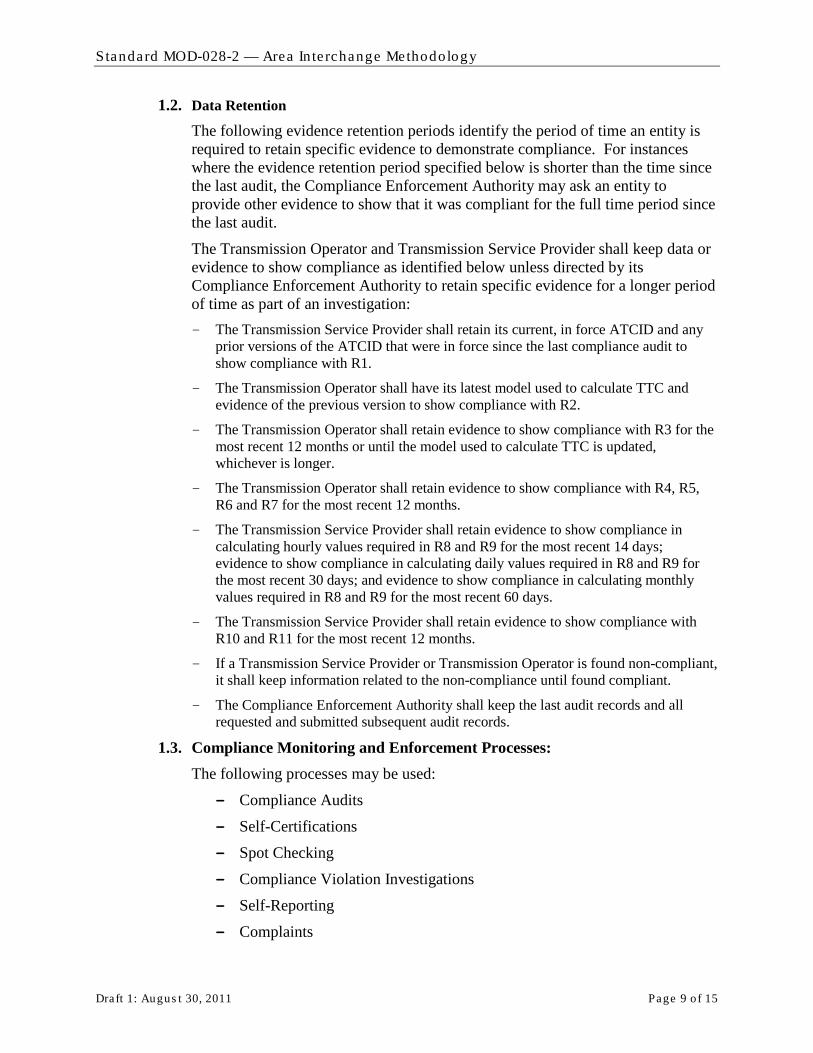
Standard MOD-028-2 — Area In te rchange Methodology
Draft 1: Augus t 30, 2011 Page 9 o f 15
1.2. Data Retention
The following evidence retention periods identify the period of time an entity is required to retain specific evidence to demonstrate compliance. For instances where the evidence retention period specified below is shorter than the time since the last audit, the Compliance Enforcement Authority may ask an entity to provide other evidence to show that it was compliant for the full time period since the last audit.
The Transmission Operator and Transmission Service Provider shall keep data or evidence to show compliance as identified below unless directed by its Compliance Enforcement Authority to retain specific evidence for a longer period of time as part of an investigation:
- The Transmission Service Provider shall retain its current, in force ATCID and any prior versions of the ATCID that were in force since the last compliance audit to show compliance with R1.
- The Transmission Operator shall have its latest model used to calculate TTC and evidence of the previous version to show compliance with R2.
- The Transmission Operator shall retain evidence to show compliance with R3 for the most recent 12 months or until the model used to calculate TTC is updated, whichever is longer.
- The Transmission Operator shall retain evidence to show compliance with R4, R5, R6 and R7 for the most recent 12 months.
- The Transmission Service Provider shall retain evidence to show compliance in calculating hourly values required in R8 and R9 for the most recent 14 days; evidence to show compliance in calculating daily values required in R8 and R9 for the most recent 30 days; and evidence to show compliance in calculating monthly values required in R8 and R9 for the most recent 60 days.
- The Transmission Service Provider shall retain evidence to show compliance with R10 and R11 for the most recent 12 months.
- If a Transmission Service Provider or Transmission Operator is found non-compliant, it shall keep information related to the non-compliance until found compliant.
- The Compliance Enforcement Authority shall keep the last audit records and all requested and submitted subsequent audit records.
1.3. Compliance Monitoring and Enforcement Processes: The following processes may be used:
- Compliance Audits
- Self-Certifications
- Spot Checking
- Compliance Violation Investigations
- Self-Reporting
- Complaints

Standard MOD-028-2 — Area In te rchange Methodology
Draft 1: Augus t 30, 2011 Page 10 of 15
1.4. Additional Compliance Information None.

Standard MOD-028-2 — Area In te rchange Methodology
Draft 1: Augus t 30, 2011 Page 11 of 15
2. Violation Severity Levels
R # Lower VSL Moderate VSL High VSL Severe VSL
R1. The Transmission Service Provider has an ATCID but it is missing one of the following:
R1.1
R1.2
R1.3
R1.4
R1.5 (any one or more of its sub-subrequirements)
The Transmission Service Provider has an ATCID but it is missing two of the following:
R1.1
R1.2
R1.3
R1.4
R1.5 (any one or more of its sub-subrequirements)
The Transmission Service Provider has an ATCID but it is missing three of the following:
R1.1
R1.2
R1.3
R1.4
R1.5 (any one or more of its sub-subrequirements)
The Transmission Service Provider has an ATCID but it is missing more than three of the following:
R1.1
R1.2
R1.3
R1.4
R1.5 (any one or more of its sub-subrequirements)
R2. The Transmission Operator used one to ten Facility Ratings that were different from those specified by a Transmission or Generator Owner in their Transmission model.
The Transmission Operator used eleven to twenty Facility Ratings that were different from those specified by a Transmission or Generator Owner in their Transmission model.
One or both of the following:
• The Transmission Operator used twenty-one to thirty Facility Ratings that were different from those specified by a Transmission or Generator Owner in their Transmission model.
• The Transmission Operator did not use a Transmission model that includes modeling data and topology (or equivalent representation) for one adjacent Reliability Coordinator Area.
One or more of the following:
• The Transmission Operator used more than thirty Facility Ratings that were different from those specified by a Transmission or Generator Owner in their Transmission model.
• The Transmission Operator’s model includes equivalent representation of non-radial facilities greater than 161 kV for its own Reliability Coordinator Area.
• The Transmission Operator did not use a Transmission model that includes modeling data and topology (or equivalent representation) for two or more adjacent Reliability Coordinator
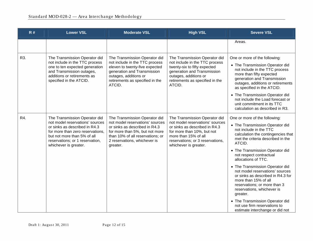
Standard MOD-028-2 — Area In te rchange Methodology
Draft 1: Augus t 30, 2011 Page 12 of 15
R # Lower VSL Moderate VSL High VSL Severe VSL
Areas.
R3. The Transmission Operator did not include in the TTC process one to ten expected generation and Transmission outages, additions or retirements as specified in the ATCID.
The Transmission Operator did not include in the TTC process eleven to twenty-five expected generation and Transmission outages, additions or retirements as specified in the ATCID.
The Transmission Operator did not include in the TTC process twenty-six to fifty expected generation and Transmission outages, additions or retirements as specified in the ATCID.
One or more of the following:
• The Transmission Operator did not include in the TTC process more than fifty expected generation and Transmission outages, additions or retirements as specified in the ATCID.
• The Transmission Operator did not include the Load forecast or unit commitment in its TTC calculation as described in R3.
R4. The Transmission Operator did not model reservations’ sources or sinks as described in R4.3 for more than zero reservations, but not more than 5% of all reservations; or 1 reservation, whichever is greater.
The Transmission Operator did not model reservations’ sources or sinks as described in R4.3 for more than 5%, but not more than 10% of all reservations; or 2 reservations, whichever is greater.
The Transmission Operator did not model reservations’ sources or sinks as described in R4.3 for more than 10%, but not more than 15% of all reservations; or 3 reservations, whichever is greater.
One or more of the following:
• The Transmission Operator did not include in the TTC calculation the contingencies that met the criteria described in the ATCID.
• The Transmission Operator did not respect contractual allocations of TTC.
• The Transmission Operator did not model reservations’ sources or sinks as described in R4.3 for more than 15% of all reservations; or more than 3 reservations, whichever is greater.
• The Transmission Operator did not use firm reservations to estimate interchange or did not
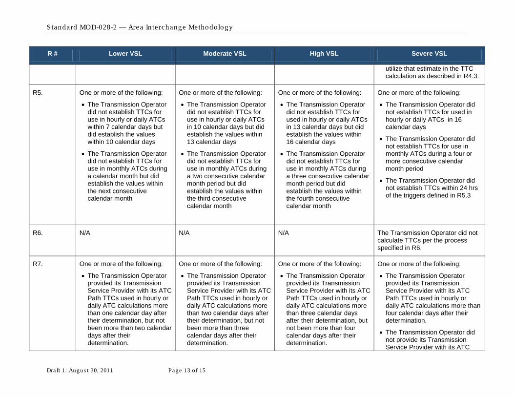
Standard MOD-028-2 — Area In te rchange Methodology
Draft 1: Augus t 30, 2011 Page 13 of 15
R # Lower VSL Moderate VSL High VSL Severe VSL
utilize that estimate in the TTC calculation as described in R4.3.
R5. One or more of the following:
• The Transmission Operator did not establish TTCs for use in hourly or daily ATCs within 7 calendar days but did establish the values within 10 calendar days
• The Transmission Operator did not establish TTCs for use in monthly ATCs during a calendar month but did establish the values within the next consecutive calendar month
One or more of the following:
• The Transmission Operator did not establish TTCs for use in hourly or daily ATCs in 10 calendar days but did establish the values within 13 calendar days
• The Transmission Operator did not establish TTCs for use in monthly ATCs during a two consecutive calendar month period but did establish the values within the third consecutive calendar month
One or more of the following:
• The Transmission Operator did not establish TTCs for used in hourly or daily ATCs in 13 calendar days but did establish the values within 16 calendar days
• The Transmission Operator did not establish TTCs for use in monthly ATCs during a three consecutive calendar month period but did establish the values within the fourth consecutive calendar month
One or more of the following:
• The Transmission Operator did not establish TTCs for used in hourly or daily ATCs in 16 calendar days
• The Transmission Operator did not establish TTCs for use in monthly ATCs during a four or more consecutive calendar month period
• The Transmission Operator did not establish TTCs within 24 hrs of the triggers defined in R5.3
R6. N/A N/A N/A The Transmission Operator did not calculate TTCs per the process specified in R6.
R7. One or more of the following:
• The Transmission Operator provided its Transmission Service Provider with its ATC Path TTCs used in hourly or daily ATC calculations more than one calendar day after their determination, but not been more than two calendar days after their determination.
One or more of the following:
• The Transmission Operator provided its Transmission Service Provider with its ATC Path TTCs used in hourly or daily ATC calculations more than two calendar days after their determination, but not been more than three calendar days after their determination.
One or more of the following:
• The Transmission Operator provided its Transmission Service Provider with its ATC Path TTCs used in hourly or daily ATC calculations more than three calendar days after their determination, but not been more than four calendar days after their determination.
One or more of the following:
• The Transmission Operator provided its Transmission Service Provider with its ATC Path TTCs used in hourly or daily ATC calculations more than four calendar days after their determination.
• The Transmission Operator did not provide its Transmission Service Provider with its ATC
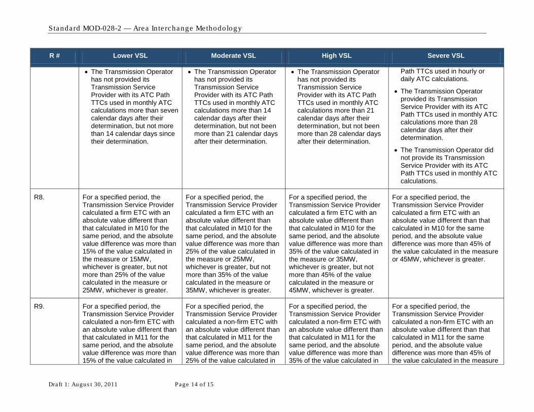
Standard MOD-028-2 — Area In te rchange Methodology
Draft 1: Augus t 30, 2011 Page 14 of 15
R # Lower VSL Moderate VSL High VSL Severe VSL
• The Transmission Operator has not provided its Transmission Service Provider with its ATC Path TTCs used in monthly ATC calculations more than seven calendar days after their determination, but not more than 14 calendar days since their determination.
• The Transmission Operator has not provided its Transmission Service Provider with its ATC Path TTCs used in monthly ATC calculations more than 14 calendar days after their determination, but not been more than 21 calendar days after their determination.
• The Transmission Operator has not provided its Transmission Service Provider with its ATC Path TTCs used in monthly ATC calculations more than 21 calendar days after their determination, but not been more than 28 calendar days after their determination.
Path TTCs used in hourly or daily ATC calculations.
• The Transmission Operator provided its Transmission Service Provider with its ATC Path TTCs used in monthly ATC calculations more than 28 calendar days after their determination.
• The Transmission Operator did not provide its Transmission Service Provider with its ATC Path TTCs used in monthly ATC calculations.
R8. For a specified period, the Transmission Service Provider calculated a firm ETC with an absolute value different than that calculated in M10 for the same period, and the absolute value difference was more than 15% of the value calculated in the measure or 15MW, whichever is greater, but not more than 25% of the value calculated in the measure or 25MW, whichever is greater.
For a specified period, the Transmission Service Provider calculated a firm ETC with an absolute value different than that calculated in M10 for the same period, and the absolute value difference was more than 25% of the value calculated in the measure or 25MW, whichever is greater, but not more than 35% of the value calculated in the measure or 35MW, whichever is greater.
For a specified period, the Transmission Service Provider calculated a firm ETC with an absolute value different than that calculated in M10 for the same period, and the absolute value difference was more than 35% of the value calculated in the measure or 35MW, whichever is greater, but not more than 45% of the value calculated in the measure or 45MW, whichever is greater.
For a specified period, the Transmission Service Provider calculated a firm ETC with an absolute value different than that calculated in M10 for the same period, and the absolute value difference was more than 45% of the value calculated in the measure or 45MW, whichever is greater.
R9. For a specified period, the Transmission Service Provider calculated a non-firm ETC with an absolute value different than that calculated in M11 for the same period, and the absolute value difference was more than 15% of the value calculated in
For a specified period, the Transmission Service Provider calculated a non-firm ETC with an absolute value different than that calculated in M11 for the same period, and the absolute value difference was more than 25% of the value calculated in
For a specified period, the Transmission Service Provider calculated a non-firm ETC with an absolute value different than that calculated in M11 for the same period, and the absolute value difference was more than 35% of the value calculated in
For a specified period, the Transmission Service Provider calculated a non-firm ETC with an absolute value different than that calculated in M11 for the same period, and the absolute value difference was more than 45% of the value calculated in the measure
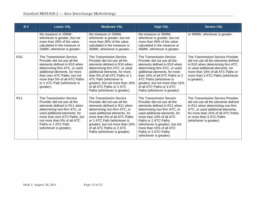
Standard MOD-028-2 — Area In te rchange Methodology
Draft 1: Augus t 30, 2011 Page 15 of 15
R # Lower VSL Moderate VSL High VSL Severe VSL
the measure or 15MW, whichever is greater, but not more than 25% of the value calculated in the measure or 25MW, whichever is greater.
the measure or 25MW, whichever is greater, but not more than 35% of the value calculated in the measure or 35MW, whichever is greater...
the measure or 35MW, whichever is greater, but not more than 45% of the value calculated in the measure or 45MW, whichever is greater.
or 45MW, whichever is greater.
R10. The Transmission Service Provider did not use all the elements defined in R10 when determining firm ATC, or used additional elements, for more than zero ATC Paths, but not more than 5% of all ATC Paths or 1 ATC Path (whichever is greater).
The Transmission Service Provider did not use all the elements defined in R10 when determining firm ATC, or used additional elements, for more than 5% of all ATC Paths or 1 ATC Path (whichever is greater), but not more than 10% of all ATC Paths or 2 ATC Paths (whichever is greater).
The Transmission Service Provider did not use all the elements defined in R10 when determining firm ATC, or used additional elements, for more than 10% of all ATC Paths or 2 ATC Paths (whichever is greater), but not more than 15% of all ATC Paths or 3 ATC Paths (whichever is greater).
The Transmission Service Provider did not use all the elements defined in R10 when determining firm ATC, or used additional elements, for more than 15% of all ATC Paths or more than 3 ATC Paths (whichever is greater).
R11. The Transmission Service Provider did not use all the elements defined in R11 when determining non-firm ATC, or used additional elements, for more than zero ATC Paths, but not more than 5% of all ATC Paths or 1 ATC Path (whichever is greater).
The Transmission Service Provider did not use all the elements defined in R11 when determining non-firm ATC, or used additional elements, for more than 5% of all ATC Paths or 1 ATC Path (whichever is greater), but not more than 10% of all ATC Paths or 2 ATC Paths (whichever is greater).
The Transmission Service Provider did not use all the elements defined in R11 when determining non-firm ATC, or used additional elements, for more than 10% of all ATC Paths or 2 ATC Paths (whichever is greater), but not more than 15% of all ATC Paths or 3 ATC Paths (whichever is greater).
The Transmission Service Provider did not use all the elements defined in R11 when determining non-firm ATC, or used additional elements, for more than 15% of all ATC Paths or more than 3 ATC Paths (whichever is greater).
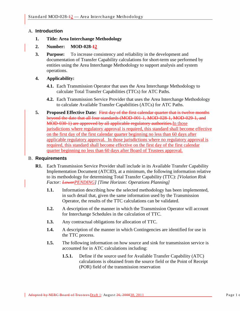
Standard MOD-028-12 — Area In te rchange Methodology
Adopted b y NERC Board of Trus tees Draft 1: Augus t 26, 200830, 2011 Page 1 o
A. Introduction 1. Title: Area Interchange Methodology 2. Number: MOD-028-12 3. Purpose: To increase consistency and reliability in the development and
documentation of Transfer Capability calculations for short-term use performed by entities using the Area Interchange Methodology to support analysis and system operations.
4. Applicability: 4.1. Each Transmission Operator that uses the Area Interchange Methodology to
calculate Total Transfer Capabilities (TTCs) for ATC Paths.
4.2. Each Transmission Service Provider that uses the Area Interchange Methodology to calculate Available Transfer Capabilities (ATCs) for ATC Paths.
5. Proposed Effective Date: First day of the first calendar quarter that is twelve months beyond the date that all four standards (MOD-001-1, MOD-028-1, MOD-029-1, and MOD-030-1) are approved by all applicable regulatory authorities.In those jurisdictions where regulatory approval is required, this standard shall become effective on the first day of the first calendar quarter beginning no less than 60 days after applicable regulatory approval. In those jurisdictions where no regulatory approval is required, this standard shall become effective on the first day of the first calendar quarter beginning no less than 60 days after Board of Trustees approval.
B. Requirements R1. Each Transmission Service Provider shall include in its Available Transfer Capability
Implementation Document (ATCID), at a minimum, the following information relative to its methodology for determining Total Transfer Capability (TTC): [Violation Risk Factor: LowerPENDING] [Time Horizon: Operations Planning] 1.1. Information describing how the selected methodology has been implemented,
in such detail that, given the same information used by the Transmission Operator, the results of the TTC calculations can be validated.
1.2. A description of the manner in which the Transmission Operator will account for Interchange Schedules in the calculation of TTC.
1.3. Any contractual obligations for allocation of TTC.
1.4. A description of the manner in which Contingencies are identified for use in the TTC process.
1.5. The following information on how source and sink for transmission service is accounted for in ATC calculations including:
1.5.1. Define if the source used for Available Transfer Capability (ATC) calculations is obtained from the source field or the Point of Receipt (POR) field of the transmission reservation
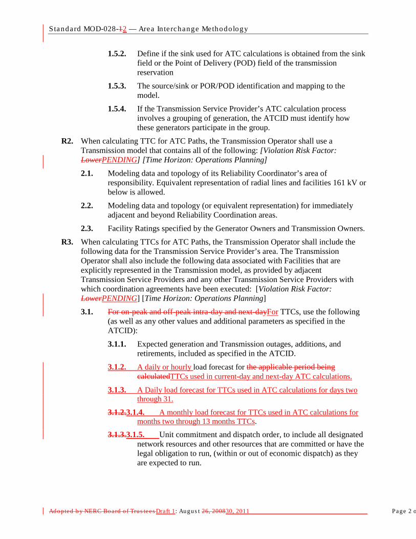
Standard MOD-028-12 — Area In te rchange Methodology
Adopted b y NERC Board of Trus tees Draft 1: Augus t 26, 200830, 2011 Page 2 o
1.5.2. Define if the sink used for ATC calculations is obtained from the sink field or the Point of Delivery (POD) field of the transmission reservation
1.5.3. The source/sink or POR/POD identification and mapping to the model.
1.5.4. If the Transmission Service Provider’s ATC calculation process involves a grouping of generation, the ATCID must identify how these generators participate in the group.
R2. When calculating TTC for ATC Paths, the Transmission Operator shall use a Transmission model that contains all of the following: [Violation Risk Factor: LowerPENDING] [Time Horizon: Operations Planning] 2.1. Modeling data and topology of its Reliability Coordinator’s area of
responsibility. Equivalent representation of radial lines and facilities 161 kV or below is allowed.
2.2. Modeling data and topology (or equivalent representation) for immediately adjacent and beyond Reliability Coordination areas.
2.3. Facility Ratings specified by the Generator Owners and Transmission Owners.
R3. When calculating TTCs for ATC Paths, the Transmission Operator shall include the following data for the Transmission Service Provider’s area. The Transmission Operator shall also include the following data associated with Facilities that are explicitly represented in the Transmission model, as provided by adjacent Transmission Service Providers and any other Transmission Service Providers with which coordination agreements have been executed: [Violation Risk Factor: LowerPENDING] [Time Horizon: Operations Planning]
3.1. For on-peak and off-peak intra-day and next-dayFor TTCs, use the following (as well as any other values and additional parameters as specified in the ATCID):
3.1.1. Expected generation and Transmission outages, additions, and retirements, included as specified in the ATCID.
3.1.2. A daily or hourly load forecast for the applicable period being calculatedTTCs used in current-day and next-day ATC calculations.
3.1.3. A Daily load forecast for TTCs used in ATC calculations for days two through 31.
3.1.2.3.1.4. A monthly load forecast for TTCs used in ATC calculations for months two through 13 months TTCs.
3.1.3.3.1.5. Unit commitment and dispatch order, to include all designated network resources and other resources that are committed or have the legal obligation to run, (within or out of economic dispatch) as they are expected to run.

Standard MOD-028-12 — Area In te rchange Methodology
Adopted b y NERC Board of Trus tees Draft 1: Augus t 26, 200830, 2011 Page 3 o
3.2. For days two through 31 TTCs and for months two through 13 TTCs, use the following (as well as any other values and internal parameters as specified in the ATCID):
3.2.1. Expected generation and Transmission outages, additions, and Retirements, included as specified in the ATCID.
3.2.2. Daily load forecast for the days two through 31 TTCs being calculated and monthly forecast for months two through 13 months TTCs being calculated.
3.2.3. Unit commitment and dispatch order, to include all designated network resources and other resources that are committed or have the legal obligation to run, (within or out of economic dispatch) as they are expected to run.
R4. When calculating TTCs for ATC Paths, the Transmission Operator shall meet all of the following conditions: [Violation Risk Factor: LowerPENDING] [Time Horizon: Operations Planning] 4.1. Use all Contingencies meeting the criteria described in the ATCID.
4.2. Respect any contractual allocations of TTC.
4.3. Include, for each time period, the Firm Transmission Service expected to be scheduled as specified in the ATCID (filtered to reduce or eliminate duplicate impacts from transactions using Transmission service from multiple Transmission Service Providers) for the Transmission Service Provider, all adjacent Transmission Service Providers, and any Transmission Service Providers with which coordination agreements have been executed modeling the source and sink as follows:
- If the source, as specified in the ATCID, has been identified in the reservation and it is discretely modeled in the Transmission Service Provider’s Transmission model, use the discretely modeled point as the source.
- If the source, as specified in the ATCID, has been identified in the reservation and the point can be mapped to an “equivalence” or “aggregate representation” in the Transmission Service Provider’s Transmission model, use the modeled equivalence or aggregate as the source.
- If the source, as specified in the ATCID, has been identified in the reservation and the point cannot be mapped to a discretely modeled point, an “equivalence,” or an “aggregate representation” in the Transmission Service Provider’s Transmission model, use the immediately adjacent Balancing Authority associated with the Transmission Service Provider from which the power is to be received as the source.
- If the source, as specified in the ATCID, has not been identified in the reservation, use the immediately adjacent Balancing Authority associated with the Transmission Service Provider from which the power is to be received as the source.
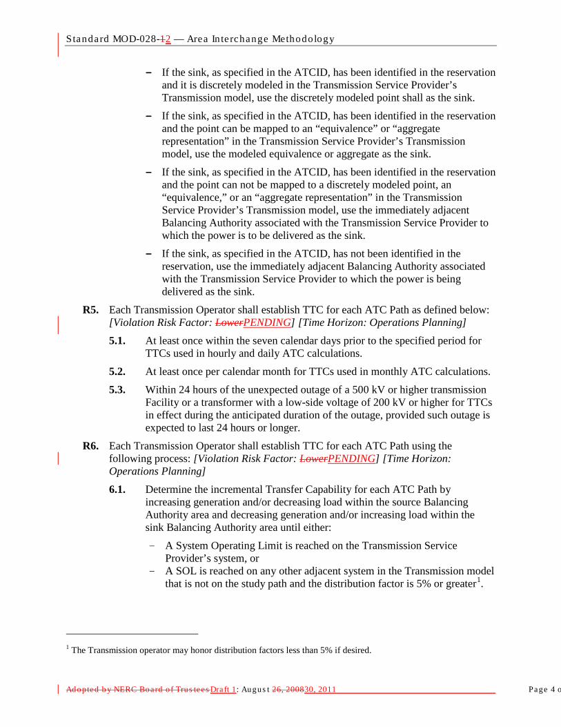
Standard MOD-028-12 — Area In te rchange Methodology
Adopted b y NERC Board of Trus tees Draft 1: Augus t 26, 200830, 2011 Page 4 o
- If the sink, as specified in the ATCID, has been identified in the reservation and it is discretely modeled in the Transmission Service Provider’s Transmission model, use the discretely modeled point shall as the sink.
- If the sink, as specified in the ATCID, has been identified in the reservation and the point can be mapped to an “equivalence” or “aggregate representation” in the Transmission Service Provider’s Transmission model, use the modeled equivalence or aggregate as the sink.
- If the sink, as specified in the ATCID, has been identified in the reservation and the point can not be mapped to a discretely modeled point, an “equivalence,” or an “aggregate representation” in the Transmission Service Provider’s Transmission model, use the immediately adjacent Balancing Authority associated with the Transmission Service Provider to which the power is to be delivered as the sink.
- If the sink, as specified in the ATCID, has not been identified in the reservation, use the immediately adjacent Balancing Authority associated with the Transmission Service Provider to which the power is being delivered as the sink.
R5. Each Transmission Operator shall establish TTC for each ATC Path as defined below: [Violation Risk Factor: LowerPENDING] [Time Horizon: Operations Planning] 5.1. At least once within the seven calendar days prior to the specified period for
TTCs used in hourly and daily ATC calculations.
5.2. At least once per calendar month for TTCs used in monthly ATC calculations.
5.3. Within 24 hours of the unexpected outage of a 500 kV or higher transmission Facility or a transformer with a low-side voltage of 200 kV or higher for TTCs in effect during the anticipated duration of the outage, provided such outage is expected to last 24 hours or longer.
R6. Each Transmission Operator shall establish TTC for each ATC Path using the following process: [Violation Risk Factor: LowerPENDING] [Time Horizon: Operations Planning] 6.1. Determine the incremental Transfer Capability for each ATC Path by
increasing generation and/or decreasing load within the source Balancing Authority area and decreasing generation and/or increasing load within the sink Balancing Authority area until either:
- A System Operating Limit is reached on the Transmission Service Provider’s system, or
- A SOL is reached on any other adjacent system in the Transmission model that is not on the study path and the distribution factor is 5% or greater1
1 The Transmission operator may honor distribution factors less than 5% if desired.
.
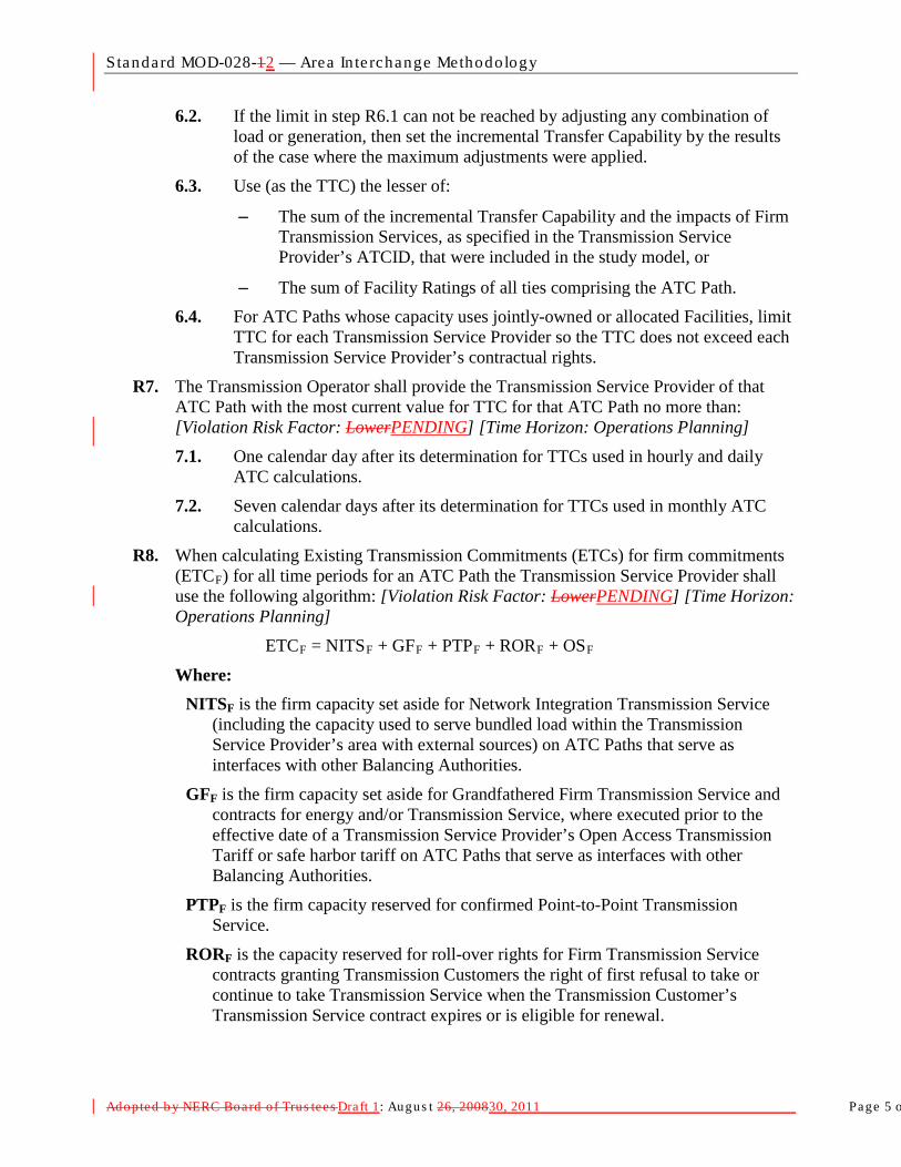
Standard MOD-028-12 — Area In te rchange Methodology
Adopted b y NERC Board of Trus tees Draft 1: Augus t 26, 200830, 2011 Page 5 o
6.2. If the limit in step R6.1 can not be reached by adjusting any combination of load or generation, then set the incremental Transfer Capability by the results of the case where the maximum adjustments were applied.
6.3. Use (as the TTC) the lesser of:
− The sum of the incremental Transfer Capability and the impacts of Firm Transmission Services, as specified in the Transmission Service Provider’s ATCID, that were included in the study model, or
− The sum of Facility Ratings of all ties comprising the ATC Path.
6.4. For ATC Paths whose capacity uses jointly-owned or allocated Facilities, limit TTC for each Transmission Service Provider so the TTC does not exceed each Transmission Service Provider’s contractual rights.
R7. The Transmission Operator shall provide the Transmission Service Provider of that ATC Path with the most current value for TTC for that ATC Path no more than: [Violation Risk Factor: LowerPENDING] [Time Horizon: Operations Planning]
7.1. One calendar day after its determination for TTCs used in hourly and daily ATC calculations.
7.2. Seven calendar days after its determination for TTCs used in monthly ATC calculations.
R8. When calculating Existing Transmission Commitments (ETCs) for firm commitments (ETCF
ETC
) for all time periods for an ATC Path the Transmission Service Provider shall use the following algorithm: [Violation Risk Factor: LowerPENDING] [Time Horizon: Operations Planning]
F = NITSF + GFF + PTPF + RORF + OS
Where: F
NITSF is the firm capacity set aside for Network Integration Transmission Service (including the capacity used to serve bundled load within the Transmission Service Provider’s area with external sources) on ATC Paths that serve as interfaces with other Balancing Authorities.
GFF is the firm capacity set aside for Grandfathered Firm Transmission Service and contracts for energy and/or Transmission Service, where executed prior to the effective date of a Transmission Service Provider’s Open Access Transmission Tariff or safe harbor tariff on ATC Paths that serve as interfaces with other Balancing Authorities.
PTPF is the firm capacity reserved for confirmed Point-to-Point Transmission Service.
RORF is the capacity reserved for roll-over rights for Firm Transmission Service contracts granting Transmission Customers the right of first refusal to take or continue to take Transmission Service when the Transmission Customer’s Transmission Service contract expires or is eligible for renewal.

Standard MOD-028-12 — Area In te rchange Methodology
Adopted b y NERC Board of Trus tees Draft 1: Augus t 26, 200830, 2011 Page 6 o
OSF is the firm capacity reserved for any other service(s), contract(s), or agreement(s) not specified above using Firm Transmission Service, including any other firm adjustments to reflect impacts from other ATC Paths of the Transmission Service Provider as specified in the ATCID.
R9. When calculating ETC for non-firm commitments (ETCNF
ETC
) for all time periods for an ATC Path the Transmission Service Provider shall use the following algorithm: [Violation Risk Factor: LowerPENDING] [Time Horizon: Operations Planning]
NF = NITSNF + GFNF + PTPNF + OS
NF
Where: NITSNF is the non-firm capacity set aside for Network Integration Transmission
Service (i.e., secondary service , including the capacity used to serve bundled load within the Transmission Service Provider’s area with external sources) reserved on ATC Paths that serve as interfaces with other Balancing Authorities.
GFNF is the non-firm capacity reserved for Grandfathered Non-Firm Transmission Service and contracts for energy and/or Transmission Service, where executed prior to the effective date of a Transmission Service Provider’s Open Access Transmission Tariff or safe harbor tariff on ATC Paths that serve as interfaces with other Balancing Authorities.
PTPNF is non-firm capacity reserved for confirmed Point-to-Point Transmission Service.
OSNF is the non-firm capacity reserved for any other service(s), contract(s), or agreement(s) not specified above using Non-Firm Transmission Service, including any other firm adjustments to reflect impacts from other ATC Paths of the Transmission Service Provider as specified in the ATCID.
R10. When calculating firm ATC for an ATC Path for a specified period, the Transmission Service Provider shall utilize the following algorithm: [Violation Risk Factor: LowerPENDING] [Time Horizon: Operations Planning]
ATCF = TTC – ETCF – CBM – TRM + PostbacksF + counterflowsF
Where: ATCF is the firm Available Transfer Capability for the ATC Path for that period.
TTC is the Total Transfer Capability of the ATC Path for that period.
ETCF is the sum of existing firm Transmission commitments for the ATC Path during that period.
CBM is the Capacity Benefit Margin for the ATC Path during that period.
TRM is the Transmission Reliability Margin for the ATC Path during that period.
PostbacksF are changes to firm ATC due to a change in the use of Transmission Service for that period, as defined in Business Practices.
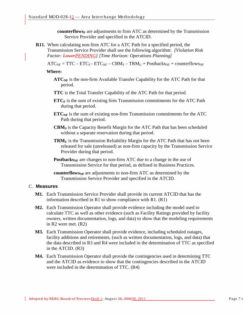
Standard MOD-028-12 — Area In te rchange Methodology
Adopted b y NERC Board of Trus tees Draft 1: Augus t 26, 200830, 2011 Page 7 o
counterflowsF are adjustments to firm ATC as determined by the Transmission Service Provider and specified in the ATCID.
R11. When calculating non-firm ATC for a ATC Path for a specified period, the Transmission Service Provider shall use the following algorithm: [Violation Risk Factor: LowerPENDING] [Time Horizon: Operations Planning] ATCNF = TTC – ETCF - ETCNF – CBMS – TRMU + PostbacksNF + counterflowsNF
Where: ATCNF is the non-firm Available Transfer Capability for the ATC Path for that
period.
TTC is the Total Transfer Capability of the ATC Path for that period.
ETCF is the sum of existing firm Transmission commitments for the ATC Path during that period.
ETCNF is the sum of existing non-firm Transmission commitments for the ATC Path during that period.
CBMS is the Capacity Benefit Margin for the ATC Path that has been scheduled without a separate reservation during that period.
TRMU is the Transmission Reliability Margin for the ATC Path that has not been released for sale (unreleased) as non-firm capacity by the Transmission Service Provider during that period.
PostbacksNF are changes to non-firm ATC due to a change in the use of Transmission Service for that period, as defined in Business Practices.
counterflowsNF are adjustments to non-firm ATC as determined by the Transmission Service Provider and specified in the ATCID.
C. Measures M1. Each Transmission Service Provider shall provide its current ATCID that has the
information described in R1 to show compliance with R1. (R1)
M2. Each Transmission Operator shall provide evidence including the model used to calculate TTC as well as other evidence (such as Facility Ratings provided by facility owners, written documentation, logs, and data) to show that the modeling requirements in R2 were met. (R2)
M3. Each Transmission Operator shall provide evidence, including scheduled outages, facility additions and retirements, (such as written documentation, logs, and data) that the data described in R3 and R4 were included in the determination of TTC as specified in the ATCID. (R3)
M4. Each Transmission Operator shall provide the contingencies used in determining TTC and the ATCID as evidence to show that the contingencies described in the ATCID were included in the determination of TTC. (R4)

Standard MOD-028-12 — Area In te rchange Methodology
Adopted b y NERC Board of Trus tees Draft 1: Augus t 26, 200830, 2011 Page 8 o
M5. Each Transmission Operator shall provide copies of contracts that contain requirements to allocate TTCs and TTC values to show that any contractual allocations of TTC were respected as required in R4.2. (R4)
M6. Each Transmission Operator shall provide evidence (such as copies of coordination agreements, reservations, interchange transactions, or other documentation) to show that firm reservations were used to estimate scheduled interchange, the modeling of scheduled interchange was based on the rules described in R4.3, and that estimated scheduled interchange was included in the determination of TTC. (R4)
M7. Each Transmission Operator shall provide evidence (such as logs and data and dated copies of requests from the Transmission Service Provider to establish TTCs at specific intervals) that TTCs have been established at least once in the calendar week prior to the specified period for TTCs used in hourly and daily ATC calculations, at least once per calendar month for TTCs used in monthly ATC calculations, and within 24 hours of the unexpected outage of a 500 kV or higher transmission Facility or a autotransformer with a low-side voltage of 200 kV or higher for TTCs in effect during the anticipated duration of the outage; provided such outage is expected to last 24 hours or longer in duration per the specifications in R5.(R5)
M8. Each Transmission Operator shall provide evidence (such as written documentation) that TTCs have been calculated using the process described in R6. (R6)
M9. Each Transmission Operator shall have evidence including a copy of the latest calculated TTC values along with a dated copy of email notices or other equivalent evidence to show that it provided its Transmission Service Provider with the most current values for TTC in accordance with R7. (R7)
M10. The Transmission Service Provider shall demonstrate compliance with R8 by recalculating firm ETC
M11. The Transmission Service Provider shall demonstrate compliance with R9 by recalculating non-firm ETC for any specific time period as described in (MOD-001 R2), using the algorithm defined in R9 and with data used to calculate the specified value for the designated time period. The data used must meet the requirements specified in MOD-028-1 and the ATCID. To account for differences that may occur when recalculating the value (due to mixing automated and manual processes), any recalculated value that is within +/- 15% or 15 MW, whichever is greater, of the originally calculated value, is evidence that the Transmission Service Provider used the algorithm in R8 to calculate its non-firm ETC. (R9)
for any specific time period as described in (MOD-001 R2), using the algorithm defined in R8 and with data used to calculate the specified value for the designated time period. The data used must meet the requirements specified in MOD-028-1 and the ATCID. To account for differences that may occur when recalculating the value (due to mixing automated and manual processes), any recalculated value that is within +/- 15% or 15 MW, whichever is greater, of the originally calculated value, is evidence that the Transmission Service Provider used the algorithm in R8 to calculate its firm ETC. (R8)
M12. Each Transmission Service Provider shall produce the supporting documentation for the processes used to implement the algorithm that calculates firm ATCs, as required in

Standard MOD-028-12 — Area In te rchange Methodology
Adopted b y NERC Board of Trus tees Draft 1: Augus t 26, 200830, 2011 Page 9 o
R10. Such documentation must show that only the variables allowed in R10 were used to calculate firm ATCs, and that the processes use the current values for the variables as determined in the requirements or definitions. Note that any variable may legitimately be zero if the value is not applicable or calculated to be zero (such as counterflows, TRM, CBM, etc…). The supporting documentation may be provided in the same form and format as stored by the Transmission Service Provider. (R10)
M13. Each Transmission Service Provider shall produce the supporting documentation for the processes used to implement the algorithm that calculates non-firm ATCs, as required in R11. Such documentation must show that only the variables allowed in R11 were used to calculate non-firm ATCs, and that the processes use the current values for the variables as determined in the requirements or definitions. Note that any variable may legitimately be zero if the value is not applicable or calculated to be zero (such as counterflows, TRM, CBM, etc…). The supporting documentation may be provided in the same form and format as stored by the Transmission Service Provider. (R11)
D. Compliance 1. Compliance Monitoring Process
1.1. Compliance Enforcement Authority For entities that do not work for the Regional Entity.
, the Regional Entity shall serve as the Compliance Monitoring Period and ResetEnforcement Authority. Not applicable.
For functional entities that work for their Regional Entity, the ERO or a Regional Entity approved by the ERO and FERC or other applicable governmental authorities shall serve as the Compliance Enforcement Authority.
1.2. Data Retention
The following evidence retention periods identify the period of time an entity is required to retain specific evidence to demonstrate compliance. For instances where the evidence retention period specified below is shorter than the time since the last audit, the Compliance Enforcement Authority may ask an entity to provide other evidence to show that it was compliant for the full time period since the last audit.
The Transmission Operator and Transmission Service Provider shall keep data or evidence to show compliance as identified below unless directed by its Compliance Enforcement Authority to retain specific evidence for a longer period of time as part of an investigation:
- The Transmission Service Provider shall retain its current, in force ATCID and any prior versions of the ATCID that were in force since the last compliance audit to show compliance with R1.
- The Transmission Operator shall have its latest model used to calculate TTC and evidence of the previous version to show compliance with R2.

Standard MOD-028-12 — Area In te rchange Methodology
Adopted b y NERC Board of Trus tees Draft 1: Augus t 26, 200830, 2011 Page 10
- The Transmission Operator shall retain evidence to show compliance with R3 for the most recent 12 months or until the model used to calculate TTC is updated, whichever is longer.
- The Transmission Operator shall retain evidence to show compliance with R4, R5, R6 and R7 for the most recent 12 months.
- The Transmission Service Provider shall retain evidence to show compliance in calculating hourly values required in R8 and R9 for the most recent 14 days; evidence to show compliance in calculating daily values required in R8 and R9 for the most recent 30 days; and evidence to show compliance in calculating monthly values required in R8 and R9 for the most recent 60 days.
- The Transmission Service Provider shall retain evidence to show compliance with R10 and R11 for the most recent 12 months.
- If a Transmission Service Provider or Transmission Operator is found non-compliant, it shall keep information related to the non-compliance until found compliant.
- The Compliance Enforcement Authority shall keep the last audit records and all requested and submitted subsequent audit records.
1.3. Compliance Monitoring and Enforcement Processes: The following processes may be used:
- Compliance Audits
- Self-Certifications
- Spot Checking
- Compliance Violation Investigations
- Self-Reporting
- Complaints
1.4. Additional Compliance Information None.
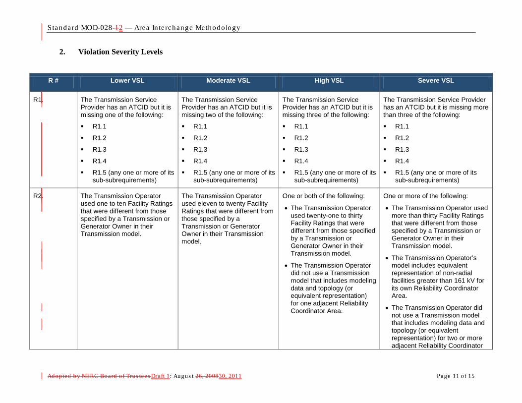
Standard MOD-028-12 — Area In te rchange Methodology
Adopted b y NERC Board of Trus tees Draft 1: Augus t 26, 200830, 2011 Page 11 of 15
2. Violation Severity Levels
R # Lower VSL Moderate VSL High VSL Severe VSL
R1. The Transmission Service Provider has an ATCID but it is missing one of the following:
R1.1
R1.2
R1.3
R1.4
R1.5 (any one or more of its sub-subrequirements)
The Transmission Service Provider has an ATCID but it is missing two of the following:
R1.1
R1.2
R1.3
R1.4
R1.5 (any one or more of its sub-subrequirements)
The Transmission Service Provider has an ATCID but it is missing three of the following:
R1.1
R1.2
R1.3
R1.4
R1.5 (any one or more of its sub-subrequirements)
The Transmission Service Provider has an ATCID but it is missing more than three of the following:
R1.1
R1.2
R1.3
R1.4
R1.5 (any one or more of its sub-subrequirements)
R2. The Transmission Operator used one to ten Facility Ratings that were different from those specified by a Transmission or Generator Owner in their Transmission model.
The Transmission Operator used eleven to twenty Facility Ratings that were different from those specified by a Transmission or Generator Owner in their Transmission model.
One or both of the following:
• The Transmission Operator used twenty-one to thirty Facility Ratings that were different from those specified by a Transmission or Generator Owner in their Transmission model.
• The Transmission Operator did not use a Transmission model that includes modeling data and topology (or equivalent representation) for one adjacent Reliability Coordinator Area.
One or more of the following:
• The Transmission Operator used more than thirty Facility Ratings that were different from those specified by a Transmission or Generator Owner in their Transmission model.
• The Transmission Operator’s model includes equivalent representation of non-radial facilities greater than 161 kV for its own Reliability Coordinator Area.
• The Transmission Operator did not use a Transmission model that includes modeling data and topology (or equivalent representation) for two or more adjacent Reliability Coordinator
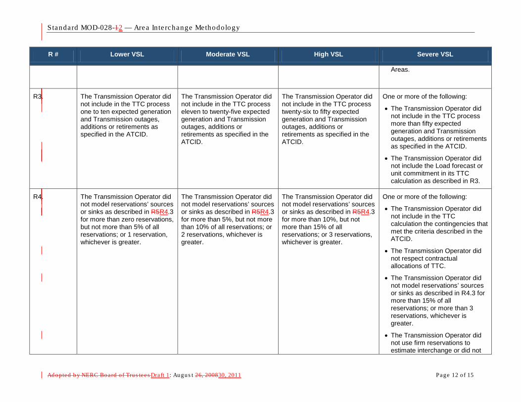
Standard MOD-028-12 — Area In te rchange Methodology
Adopted b y NERC Board of Trus tees Draft 1: Augus t 26, 200830, 2011 Page 12 of 15
R # Lower VSL Moderate VSL High VSL Severe VSL
Areas.
R3. The Transmission Operator did not include in the TTC process one to ten expected generation and Transmission outages, additions or retirements as specified in the ATCID.
The Transmission Operator did not include in the TTC process eleven to twenty-five expected generation and Transmission outages, additions or retirements as specified in the ATCID.
The Transmission Operator did not include in the TTC process twenty-six to fifty expected generation and Transmission outages, additions or retirements as specified in the ATCID.
One or more of the following:
• The Transmission Operator did not include in the TTC process more than fifty expected generation and Transmission outages, additions or retirements as specified in the ATCID.
• The Transmission Operator did not include the Load forecast or unit commitment in its TTC calculation as described in R3.
R4. The Transmission Operator did not model reservations’ sources or sinks as described in R5R4.3 for more than zero reservations, but not more than 5% of all reservations; or 1 reservation, whichever is greater.
The Transmission Operator did not model reservations’ sources or sinks as described in R5R4.3 for more than 5%, but not more than 10% of all reservations; or 2 reservations, whichever is greater.
The Transmission Operator did not model reservations’ sources or sinks as described in R5R4.3 for more than 10%, but not more than 15% of all reservations; or 3 reservations, whichever is greater.
One or more of the following:
• The Transmission Operator did not include in the TTC calculation the contingencies that met the criteria described in the ATCID.
• The Transmission Operator did not respect contractual allocations of TTC.
• The Transmission Operator did not model reservations’ sources or sinks as described in R4.3 for more than 15% of all reservations; or more than 3 reservations, whichever is greater.
• The Transmission Operator did not use firm reservations to estimate interchange or did not

Standard MOD-028-12 — Area In te rchange Methodology
Adopted b y NERC Board of Trus tees Draft 1: Augus t 26, 200830, 2011 Page 13 of 15
R # Lower VSL Moderate VSL High VSL Severe VSL
utilize that estimate in the TTC calculation as described in R4.3.
R5. One or more of the following:
• The Transmission Operator did not establish TTCs for use in hourly or daily ATCs within 7 calendar days but did establish the values within 10 calendar days
• The Transmission Operator did not establish TTCs for use in monthly ATCs during a calendar month but did establish the values within the next consecutive calendar month
One or more of the following:
• The Transmission Operator did not establish TTCs for use in hourly or daily ATCs in 10 calendar days but did establish the values within 13 calendar days
• The Transmission Operator did not establish TTCs for use in monthly ATCs during a two consecutive calendar month period but did establish the values within the third consecutive calendar month
One or more of the following:
• The Transmission Operator did not establish TTCs for used in hourly or daily ATCs in 13 calendar days but did establish the values within 16 calendar days
• The Transmission Operator did not establish TTCs for use in monthly ATCs during a three consecutive calendar month period but did establish the values within the fourth consecutive calendar month
One or more of the following:
• The Transmission Operator did not establish TTCs for used in hourly or daily ATCs in 16 calendar days
• The Transmission Operator did not establish TTCs for use in monthly ATCs during a four or more consecutive calendar month period
• The Transmission Operator did not establish TTCs within 24 hrs of the triggers defined in R5.3
R6. N/A N/A N/A The Transmission Operator did not calculate TTCs per the process specified in R6.
R7. One or more of the following:
• The Transmission Operator provided its Transmission Service Provider with its ATC Path TTCs used in hourly or daily ATC calculations more than one calendar day after their determination, but not been more than two calendar days after their determination.
One or more of the following:
• The Transmission Operator provided its Transmission Service Provider with its ATC Path TTCs used in hourly or daily ATC calculations more than two calendar days after their determination, but not been more than three calendar days after their determination.
One or more of the following:
• The Transmission Operator provided its Transmission Service Provider with its ATC Path TTCs used in hourly or daily ATC calculations more than three calendar days after their determination, but not been more than four calendar days after their determination.
One or more of the following:
• The Transmission Operator provided its Transmission Service Provider with its ATC Path TTCs used in hourly or daily ATC calculations more than four calendar days after their determination.
• The Transmission Operator did not provide its Transmission Service Provider with its ATC
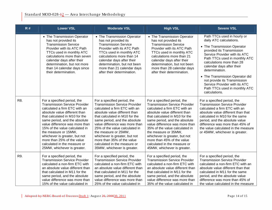
Standard MOD-028-12 — Area In te rchange Methodology
Adopted b y NERC Board of Trus tees Draft 1: Augus t 26, 200830, 2011 Page 14 of 15
R # Lower VSL Moderate VSL High VSL Severe VSL
• The Transmission Operator has not provided its Transmission Service Provider with its ATC Path TTCs used in monthly ATC calculations more than seven calendar days after their determination, but not more than 14 calendar days since their determination.
• The Transmission Operator has not provided its Transmission Service Provider with its ATC Path TTCs used in monthly ATC calculations more than 14 calendar days after their determination, but not been more than 21 calendar days after their determination.
• The Transmission Operator has not provided its Transmission Service Provider with its ATC Path TTCs used in monthly ATC calculations more than 21 calendar days after their determination, but not been more than 28 calendar days after their determination.
Path TTCs used in hourly or daily ATC calculations.
• The Transmission Operator provided its Transmission Service Provider with its ATC Path TTCs used in monthly ATC calculations more than 28 calendar days after their determination.
• The Transmission Operator did not provide its Transmission Service Provider with its ATC Path TTCs used in monthly ATC calculations.
R8. For a specified period, the Transmission Service Provider calculated a firm ETC with an absolute value different than that calculated in M10 for the same period, and the absolute value difference was more than 15% of the value calculated in the measure or 15MW, whichever is greater, but not more than 25% of the value calculated in the measure or 25MW, whichever is greater.
For a specified period, the Transmission Service Provider calculated a firm ETC with an absolute value different than that calculated in M10 for the same period, and the absolute value difference was more than 25% of the value calculated in the measure or 25MW, whichever is greater, but not more than 35% of the value calculated in the measure or 35MW, whichever is greater.
For a specified period, the Transmission Service Provider calculated a firm ETC with an absolute value different than that calculated in M10 for the same period, and the absolute value difference was more than 35% of the value calculated in the measure or 35MW, whichever is greater, but not more than 45% of the value calculated in the measure or 45MW, whichever is greater.
For a specified period, the Transmission Service Provider calculated a firm ETC with an absolute value different than that calculated in M10 for the same period, and the absolute value difference was more than 45% of the value calculated in the measure or 45MW, whichever is greater.
R9. For a specified period, the Transmission Service Provider calculated a non-firm ETC with an absolute value different than that calculated in M11 for the same period, and the absolute value difference was more than 15% of the value calculated in
For a specified period, the Transmission Service Provider calculated a non-firm ETC with an absolute value different than that calculated in M11 for the same period, and the absolute value difference was more than 25% of the value calculated in
For a specified period, the Transmission Service Provider calculated a non-firm ETC with an absolute value different than that calculated in M11 for the same period, and the absolute value difference was more than 35% of the value calculated in
For a specified period, the Transmission Service Provider calculated a non-firm ETC with an absolute value different than that calculated in M11 for the same period, and the absolute value difference was more than 45% of the value calculated in the measure
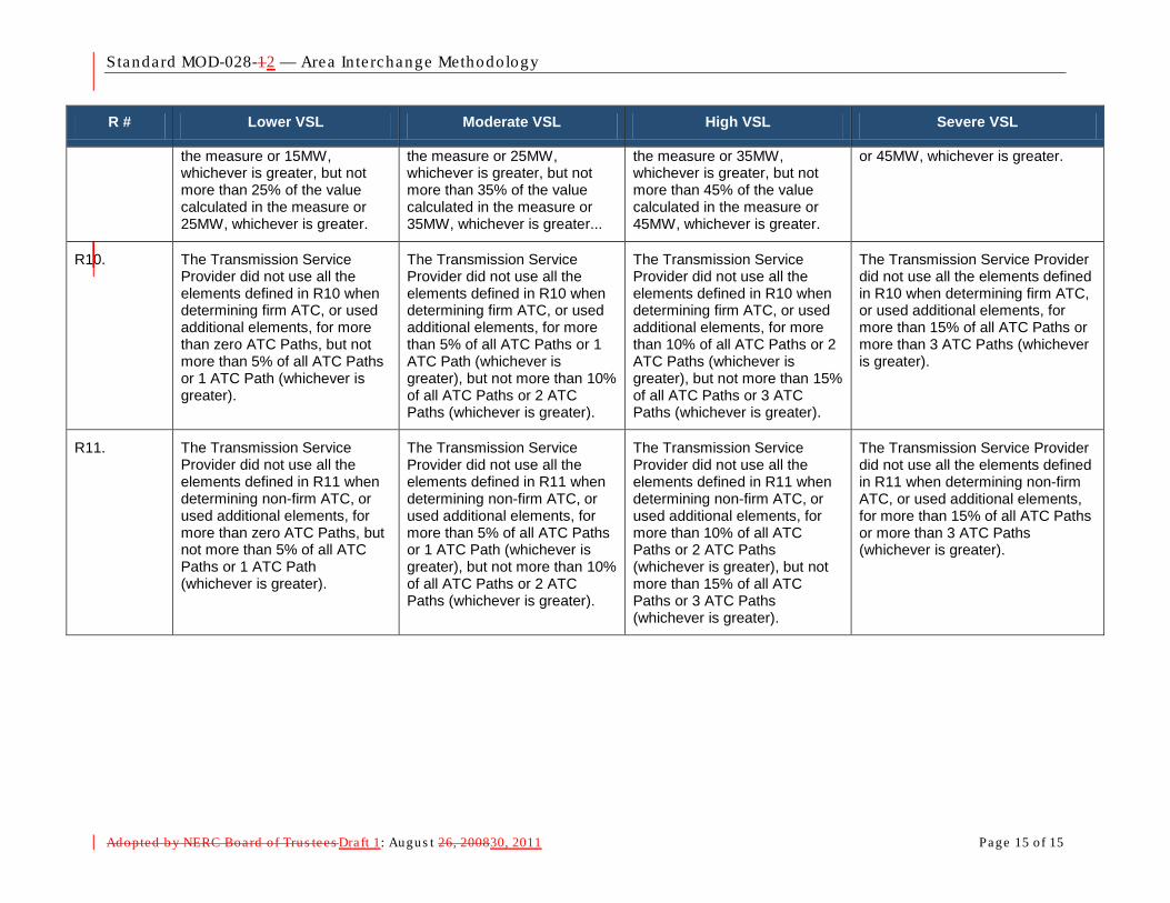
Standard MOD-028-12 — Area In te rchange Methodology
Adopted b y NERC Board of Trus tees Draft 1: Augus t 26, 200830, 2011 Page 15 of 15
R # Lower VSL Moderate VSL High VSL Severe VSL
the measure or 15MW, whichever is greater, but not more than 25% of the value calculated in the measure or 25MW, whichever is greater.
the measure or 25MW, whichever is greater, but not more than 35% of the value calculated in the measure or 35MW, whichever is greater...
the measure or 35MW, whichever is greater, but not more than 45% of the value calculated in the measure or 45MW, whichever is greater.
or 45MW, whichever is greater.
R10. The Transmission Service Provider did not use all the elements defined in R10 when determining firm ATC, or used additional elements, for more than zero ATC Paths, but not more than 5% of all ATC Paths or 1 ATC Path (whichever is greater).
The Transmission Service Provider did not use all the elements defined in R10 when determining firm ATC, or used additional elements, for more than 5% of all ATC Paths or 1 ATC Path (whichever is greater), but not more than 10% of all ATC Paths or 2 ATC Paths (whichever is greater).
The Transmission Service Provider did not use all the elements defined in R10 when determining firm ATC, or used additional elements, for more than 10% of all ATC Paths or 2 ATC Paths (whichever is greater), but not more than 15% of all ATC Paths or 3 ATC Paths (whichever is greater).
The Transmission Service Provider did not use all the elements defined in R10 when determining firm ATC, or used additional elements, for more than 15% of all ATC Paths or more than 3 ATC Paths (whichever is greater).
R11. The Transmission Service Provider did not use all the elements defined in R11 when determining non-firm ATC, or used additional elements, for more than zero ATC Paths, but not more than 5% of all ATC Paths or 1 ATC Path (whichever is greater).
The Transmission Service Provider did not use all the elements defined in R11 when determining non-firm ATC, or used additional elements, for more than 5% of all ATC Paths or 1 ATC Path (whichever is greater), but not more than 10% of all ATC Paths or 2 ATC Paths (whichever is greater).
The Transmission Service Provider did not use all the elements defined in R11 when determining non-firm ATC, or used additional elements, for more than 10% of all ATC Paths or 2 ATC Paths (whichever is greater), but not more than 15% of all ATC Paths or 3 ATC Paths (whichever is greater).
The Transmission Service Provider did not use all the elements defined in R11 when determining non-firm ATC, or used additional elements, for more than 15% of all ATC Paths or more than 3 ATC Paths (whichever is greater).
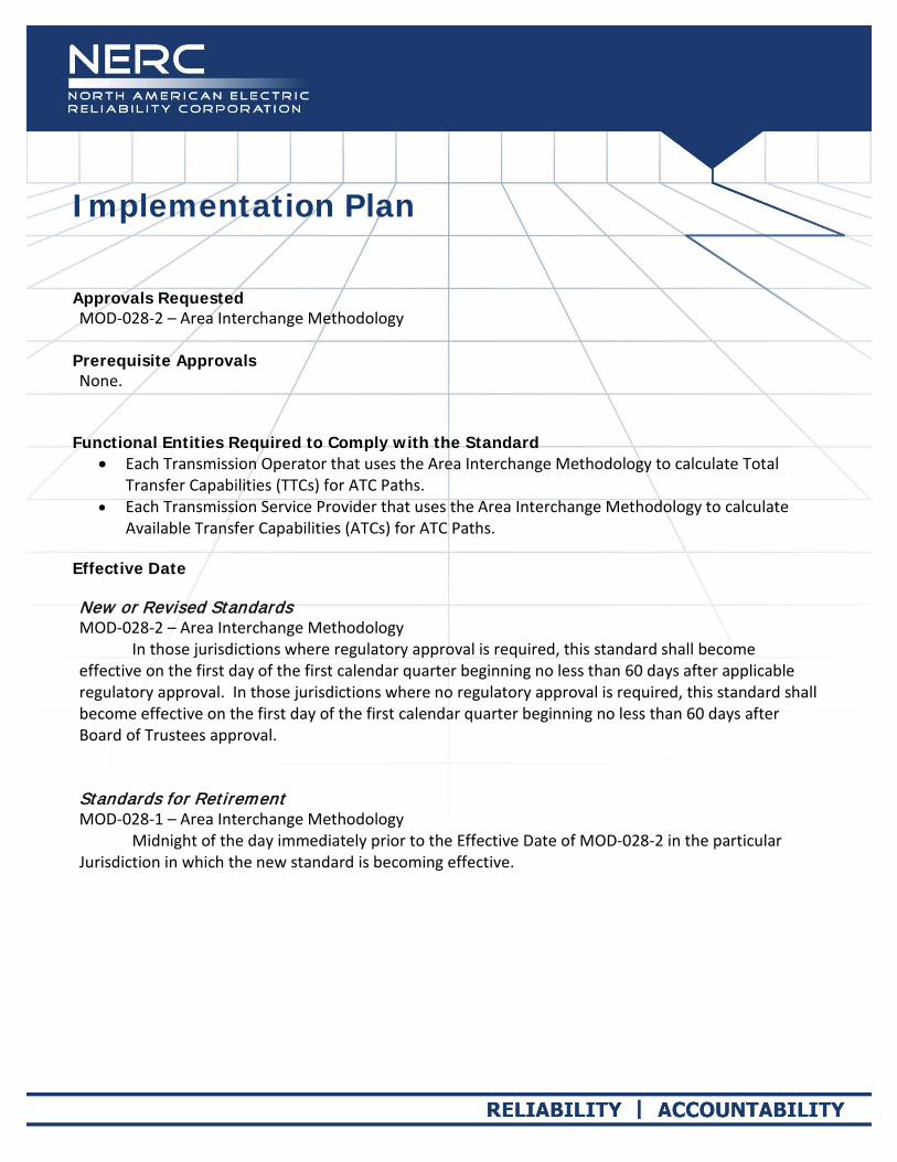
Implementation Plan
Approvals Requested MOD-028-2 – Area Interchange Methodology
Prerequisite Approvals None.
Functional Entities Required to Comply with the Standard
•
•
Each Transmission Operator that uses the Area Interchange Methodology to calculate Total Transfer Capabilities (TTCs) for ATC Paths.
Each Transmission Service Provider that uses the Area Interchange Methodology to calculate Available Transfer Capabilities (ATCs) for ATC Paths.
Effective Date New or Revised Standards MOD-028-2 – Area Interchange Methodology
In those jurisdictions where regulatory approval is required, this standard shall become effective on the first day of the first calendar quarter beginning no less than 60 days after applicable regulatory approval. In those jurisdictions where no regulatory approval is required, this standard shall become effective on the first day of the first calendar quarter beginning no less than 60 days after Board of Trustees approval. Standards for Retirement MOD-028-1 – Area Interchange Methodology Midnight of the day immediately prior to the Effective Date of MOD-028-2 in the particular Jurisdiction in which the new standard is becoming effective.

116-390 Village Blvd. Princeton, NJ 08540
609.452.8060 | www.nerc.com
Note: A valid interpretation request is one that requests additional clarity about one or more requirements in approved NERC reliability standards, but does not request approval as to how to comply with one or more requirements.
Request for an Interpretation of a Reliability Standard
Date submitted: 5/13/2011
Contact information for person requesting the interpretation:
Name: Don McInnis
Organization: Florida Power & Light
Telephone: 305-442-5272 E-mail: [email protected]
Identify the standard that needs clarification:
Standard Number (include version number, e.g. PRC-001-1 ): MOD-028-1
Standard Title: Area Interchange Methodology
Identify specifically what requirement needs clarification:
Requirement Number and Text of Requirement: R3.1 For on-peak and off-peak intra-day and next-day TTCs, use the following (as well as any other values and additional parameters as specified in the ATCID):
Identify the nature of clarification that is requested: (Check as many as applicable)
Clarify the required performance
Clarify the conditions under which the performance is required
Clarify which functional entity is responsible for performing an action in a requirement
Clarify the reliability outcome the requirement is intended to produce
Please explain the clarification needed:
By using the words “on-peak”, “off-peak”, and “intra-day” this requirement implies there would have to be separate TTC numbers for different portions of the current day. However, R5 of MOD28 establishes the calculation frequencies and only requires an update to TTC once within the 7 days prior to the specified period where they are used in an ATC calculation. The
When completed, email this form to: [email protected] For questions about this form or for assistance in completing the form, call Laura Hussey at 404-446-2579.

116-390 Village Blvd. Princeton, NJ 08540
609.452.8060 | www.nerc.com
clarification needed is on the ATC Drafting Team’s intent with respect to the quantity and timing of individual TTC calculations needed for use in the ATC calculations.
Identify the material impact associated with this interpretation:
Identify the material impact to your organization or others, if known, caused by the lack of clarity or an incorrect interpretation of this standard.
Adherence to the implied intra day calculation requirement of R3.1 is resulting in additional work and creating coordination issues with other parties which are not calculating intra day TTC values.

Unofficial Comment Form Project 2011-INT-01 Interpretation of MOD-028 R3.1 for FPL
1
Unofficial Comment Form (Standard) Project 2011-INT-01 – Interpretation of MOD-028 R3.1 for FPL Instructions Please DO NOT use this form for official commenting. Please use the electronic form to submit comments on the SAR and draft MOD-028-2 standard (Area Interchange Methodology). The electronic comment form must be completed November 16, 2011. If you have questions please contact Monica Benson at [email protected] or by telephone at 404-446-2573. http://www.nerc.com/filez/standards/2011-INT-01_Interpretation_MOD-028-1_FPL.html Background Information MOD-028-1 Area Interchange Methodology is one of the three methodologies included in the ATC-Related MOD standards. Sub-requirement R3.1 of MOD-028-1 states the following: R3.1 For on-peak and off-peak intra-day and next-day TTCs, use the following (as well as any other values and additional parameters as specified in the ATCID): NERC received a request to interpret this sub-requirement. The requester stated:
By using the words “on-peak”, “off-peak”, and “intra-day” this requirement implies there would have to be separate TTC numbers for different portions of the current day. However, R5 of MOD-28 establishes the calculation frequencies and only requires an update to TTC once within the 7 days prior to the specified period where they are used in an ATC calculation. The clarification needed is on the ATC Drafting Team’s intent with respect to the quantity and timing of individual TTC calculations needed for use in the ATC calculations. Adherence to the implied intra day calculation requirement of R3.1 is resulting in additional work and creating coordination issues with other parties which are not calculating intra day TTC values.
NERC assembled an Interpretation team made up of some of the members of the original ATC-TTC-CBM-TRM Drafting Team. While that Interpretation team was preparing its Interpretation, the Standards Committee requested the Interpretation Team use a “rapid revision” approach to clarify the requirement in question directly. (The Standards Committee confirmed that revising the standard rather than developing an interpretation was acceptable to the requester.) The Interpretation team discussed this approach, and developed a revision to the standard that is intended to eliminate the ambiguity present in the current version of the standard. Other minor corrections and errata were addressed as well.

Unofficial Comment Form Project 2011-INT-01 Interpretation of MOD-028 R3.1 for FPL
2
Questions
1. Do you agree with the use of this “Rapid” approach to clarify the standard, rather than clarifying the standard through an Interpretation? If No, please explain your concerns.
Yes
No
Comments:
2. Does the language in the SAR adequately represent the issue raised in the interpretation request? If No, please provide your suggestions to modify the SAR.
Yes
No
Comments:
3. Does the proposed revision resolve the issue raised in the interpretation request? If No, please provide your suggestions to modify the standard.
Yes
No
Comments:
4. If you have any other comments on the SAR or on the proposed Standard that you have not provided above, please provide them here.
Comments:

Standards Announcement Interpretation 2011-INT-01- Rapid Revision of MOD-028-1 for FPL to Address Request for Interpretation
Ballot Window Now Open Through Wednesday, November 16, 2011 Now Available Please note that although the project number and name reference that this is an interpretation, this project is a revision to MOD-028-1 – Area Interchange Methodology. In May 2011, Florida Power & Light Company (FPL) requested an interpretation of MOD-028-1 – Area Interchange Methodology, Requirement R3.1. The request asks for clarification of the timing and frequency of Total Transfer Capability (TTC) calculations needed for Available Transfer Capability (ATC) calculations. At its July 2011 meeting the Standards Committee approved (with FPL’s approval) addressing FPL’s request for interpretation through a rapid revision to the MOD-028-1 standard. This project is following the normal standard development process in the NERC Standard Processes Manual, rather than the interpretation process. As envisioned, making a permanent revision to the standard makes more efficient use of industry resources than providing clarity first through an interpretation and then later through a revision to the standard. A drafting team appointed by the Standards Committee has posted FPL’s request for interpretation, a SAR identifying the revisions necessary to address the requested clarification, a draft MOD-028-2 (clean and redline showing changes to the last approved version of the standard), and an associated implementation plan, for a formal 45-day comment period and initial ballot through 8 p.m. Eastern on Wednesday, November 16, 2011. Instructions for Balloting The ballot window is open from Monday, November 7, 2011 through 8 p.m. Eastern on Wednesday, November 16, 2011. Members of the ballot pool associated with this project may log in and submit their vote the standard at: https://standards.nerc.net/CurrentBallots.aspx. Special Instructions for Submitting Comments with a Ballot A formal comment period is open through 8 p.m. Eastern on Wednesday, November 16, 2011. Comments submitted with ballots are extremely valuable to help the drafting team revise its work. In an effort to reduce the burden on stakeholders providing comments, the drafting requests that all comments (both those submitted with a ballot and those submitted by stakeholders not balloting) be submitted through the electronic comment form. This will ensure that stakeholders only provide a single set of comments, but have an opportunity to notify the drafting team if they have provided comments.

Standards Announcement – 2011-INT-01 Rapid Revision of MOD-028-1 for FPL 2
When submitting a ballot with comments, submit the comments through the electronic form and then simply record “Comments submitted” in the comments field of the ballot to indicate that comments were submitted. Please note that comments submitted during the formal comment period and the ballot for the standard both use the same electronic form, and it is NOT necessary for ballot pool members to submit more than one set of comments. For entities that are vertically integrated and registered to vote in more than one industry segment, in the situation where all balloters in that company agree to a single position, one person should submit a comment form and other balloters from the same company should identify that their comments are represented by that person’s comment form by entering a phrase such as: “See comments from James Smith of XYA.” Next Steps The drafting team will consider all comments received during the formal comment period and initial ballot. Background In May 2011, FPL requested an interpretation of MOD-028-1, Requirement R3.1. The request asks for clarification of the timing and frequency of TTC calculations needed for ATC calculations. At its July 2011 meeting the Standards Committee approved addressing FPL’s request for interpretation through a rapid revision to the MOD-028-1 standard. The interpretation drafting team was appointed as the standard drafting team and directed to submit both a SAR and proposed revisions to MOD-028-1 addressing the issue raised in the request for interpretation. Because the revisions are narrowly focused on addressing the clarification requested by FPL, the Standards Committee approved waiving the initial 30-day formal comment period and directed that the SAR and proposed revisions to the standard be posted for a 45-day parallel comment period and initial ballot. Standards Development Process The Standard Processes Manual contains all the procedures governing the standards development process. The success of the NERC standards development process depends on stakeholder participation. We extend our thanks to all those who participate. For more information or assistance, please contact Monica Benson at [email protected].
For more information or assistance, please contact Monica Benson, Standards Process Administrator, at [email protected] or at 404-446-2560.
North American Electric Reliability Corporation 116-390 Village Blvd. Princeton, NJ 08540
609.452.8060 | www.nerc.com

Standards Announcement
Project 2011-INT-01 Interpretation of MOD-028-1 for FPL Ballot Pool Window Open: October 4 – November 2, 2011 Formal Comment Period Open: October 4 – November 16, 2011 Initial Ballot Window: November 7 – November 16, 2011 Now available
In May 2011, Florida Power & Light Company (FPL) requested an interpretation of MOD-028-1 – Area Interchange Methodology, Requirement R3.1. The request asks for clarification of the timing and frequency of Total Transfer Capability (TTC) calculations needed for Available Transfer Capability (ATC) calculations. At its July 2011 meeting the Standards Committee approved (with FPL’s approval) addressing FPL’s request for interpretation through a rapid revision to the MOD-028-1 standard. As envisioned, making a permanent revision to the standard makes more efficient use of industry resources than providing clarity first through an interpretation and then later through a revision to the standard. A drafting team appointed by the Standards Committee has posted FPL’s request for interpretation, a SAR identifying the revisions necessary to address the requested clarification, a draft MOD-028-2 (clean and redline showing changes to the last approved version of the standard), and an associated implementation plan, for a formal 45-day comment period through 8 p.m. Eastern on Wednesday, November 16, 2011. Because the revisions are narrowly focused on addressing the clarification requested by FPL, the Standards Committee approved waiving the initial 30-day formal comment period. A ballot pool is open through 8 a.m. Eastern on Wednesday, November 2. Ballot Pool Open through 8 a.m. Eastern on Wednesday, November 2 A ballot pool is being formed for balloting the revisions to MOD-028-2. The Standards Committee has authorized posting the standard and implementation plan for a 45-day formal comment period with an initial ballot conducted during the last 10 days of that comment period. (The Standards Committee authorized waiving the initial 30-day formal comment period because the revisions to MOD-028 are narrowly focused on addressing the clarification requested in FPL’s request for interpretation.) The ballot pool is open through 8 a.m. Eastern on November 2, 2011, and the ballot window will be open from 8 a.m. Eastern on Monday, November 7 through 8 p.m. Eastern on Wednesday, November 16, 2011. Instructions for Joining the Ballot Pool for Project 2011-INT-01 Registered Ballot Body members may join the ballot pool to be eligible to vote in the upcoming ballot at the following page:
https://standards.nerc.net/BallotPool.aspx

During the pre-ballot window, members of the ballot pool may communicate with one another by using their “ballot pool list server.” (Once the balloting begins, ballot pool members are prohibited from using the ballot pool list servers.) The list server for this ballot pool is: [email protected] Instructions for Commenting Please use this electronic form to submit comments. If you experience any difficulties in using the electronic form, please contact Monica Benson at [email protected]. An off-line, unofficial copy of the comment form is posted on the project page. Next Steps An initial ballot of MOD-028-2 and its associated implementation plan will begin on Monday, November 7, 2011 and end at 8 p.m. Eastern on Wednesday, November 16, 2011.
For more information or assistance, please contact Monica Benson, Standards Process Administrator, at [email protected] or at 404-446-2560.
North American Electric Reliability Corporation 116-390 Village Blvd. Princeton, NJ 08540
609.452.8060 | www.nerc.com
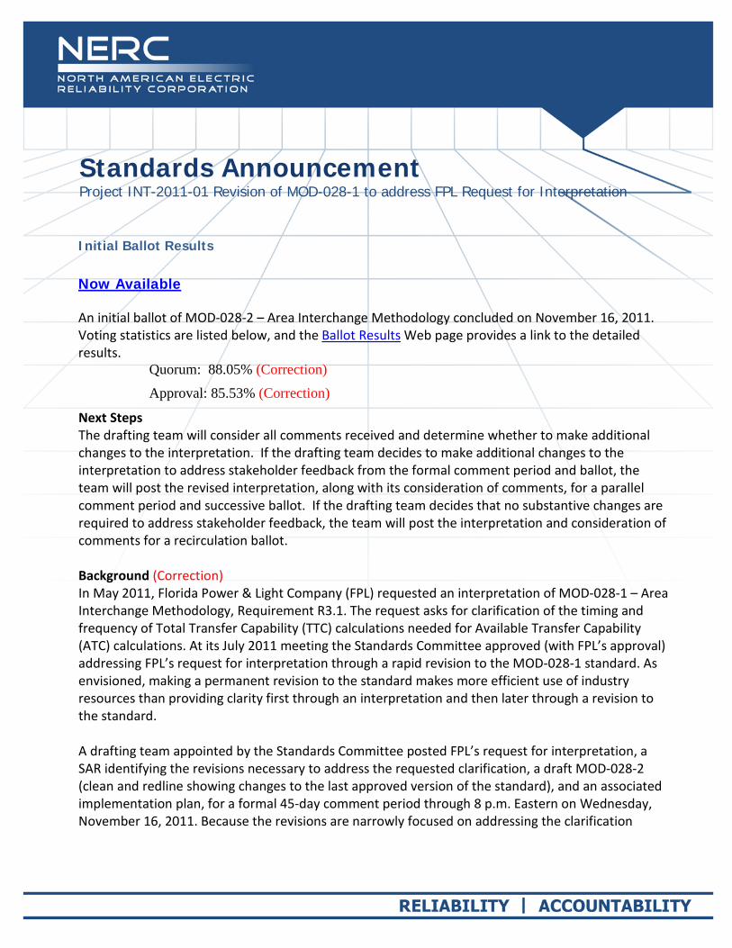
Standards Announcement Project INT-2011-01 Revision of MOD-028-1 to address FPL Request for Interpretation
Initial Ballot Results
Now Available An initial ballot of MOD-028-2 – Area Interchange Methodology concluded on November 16, 2011. Voting statistics are listed below, and the Ballot Results Web page provides a link to the detailed results.
Quorum: 88.05% (Correction)
Approval: 85.53% (Correction)
Next Steps The drafting team will consider all comments received and determine whether to make additional changes to the interpretation. If the drafting team decides to make additional changes to the interpretation to address stakeholder feedback from the formal comment period and ballot, the team will post the revised interpretation, along with its consideration of comments, for a parallel comment period and successive ballot. If the drafting team decides that no substantive changes are required to address stakeholder feedback, the team will post the interpretation and consideration of comments for a recirculation ballot. Background (Correction) In May 2011, Florida Power & Light Company (FPL) requested an interpretation of MOD-028-1 – Area Interchange Methodology, Requirement R3.1. The request asks for clarification of the timing and frequency of Total Transfer Capability (TTC) calculations needed for Available Transfer Capability (ATC) calculations. At its July 2011 meeting the Standards Committee approved (with FPL’s approval) addressing FPL’s request for interpretation through a rapid revision to the MOD-028-1 standard. As envisioned, making a permanent revision to the standard makes more efficient use of industry resources than providing clarity first through an interpretation and then later through a revision to the standard. A drafting team appointed by the Standards Committee posted FPL’s request for interpretation, a SAR identifying the revisions necessary to address the requested clarification, a draft MOD-028-2 (clean and redline showing changes to the last approved version of the standard), and an associated implementation plan, for a formal 45-day comment period through 8 p.m. Eastern on Wednesday, November 16, 2011. Because the revisions are narrowly focused on addressing the clarification

Standards Announcement INT-2011-01 Revision of MOD-028-1 2
requested by FPL, the Standards Committee approved waiving the initial 30-day formal comment period. Standards Development Process The Standard Processes Manual contains all the procedures governing the standards development process. The success of the NERC standards development process depends on stakeholder participation. We extend our thanks to all those who participate.
For more information or assistance, please contact Monica Benson,
Standards Process Administrator, at [email protected] or at 404-446-2560.
North American Electric Reliability Corporation 116-390 Village Blvd. Princeton, NJ 08540
609.452.8060 | www.nerc.com

NERC Standards
https://standards.nerc.net/BallotResults.aspx?BallotGUID=b830728a-04d6-48b5-af5a-3e7cb1566745[11/18/2011 11:06:22 AM]
Newsroom • Site Map • Contact NERC
Advanced Search
User Name
Password
Log in
Register
-Ballot Pools-Current Ballots-Ballot Results-Registered Ballot Body-Proxy Voters
Home Page
Ballot Results
Ballot Name: Project_2011_INT-01_MOD-028-1_FPL_initial_in
Ballot Period: 11/7/2011 - 11/16/2011
Ballot Type: Initial
Total # Votes: 258
Total Ballot Pool: 293
Quorum: 88.05 % The Quorum has been reached
Weighted SegmentVote:
85.53 %
Ballot Results: The standard will proceed to recirculation ballot.
Summary of Ballot Results
SegmentBallotPool
SegmentWeight
Affirmative Negative Abstain
NoVote
#Votes Fraction
#Votes Fraction # Votes
1 - Segment 1. 79 1 31 0.795 8 0.205 32 82 - Segment 2. 8 0 0 0 0 0 5 33 - Segment 3. 66 1 28 0.875 4 0.125 26 84 - Segment 4. 22 1 10 0.833 2 0.167 7 35 - Segment 5. 58 1 20 0.87 3 0.13 30 56 - Segment 6. 43 1 17 0.773 5 0.227 18 37 - Segment 7. 0 0 0 0 0 0 0 08 - Segment 8. 7 0.4 4 0.4 0 0 0 39 - Segment 9. 3 0.1 1 0.1 0 0 1 110 - Segment 10. 7 0.4 4 0.4 0 0 2 1
Totals 293 5.9 115 5.046 22 0.854 121 35
Individual Ballot Pool Results
Segment Organization Member Ballot Comments
1 Ameren Services Kirit Shah Abstain1 American Electric Power Paul B. Johnson1 Arizona Public Service Co. Robert Smith Abstain View1 Associated Electric Cooperative, Inc. John Bussman Abstain1 Balancing Authority of Northern California Kevin Smith Affirmative1 BC Hydro and Power Authority Patricia Robertson Abstain1 Beaches Energy Services Joseph S Stonecipher Affirmative1 Bonneville Power Administration Donald S. Watkins Abstain
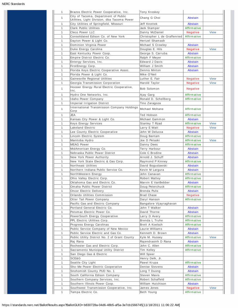
NERC Standards
https://standards.nerc.net/BallotResults.aspx?BallotGUID=b830728a-04d6-48b5-af5a-3e7cb1566745[11/18/2011 11:06:22 AM]
1 Brazos Electric Power Cooperative, Inc. Tony Kroskey
1 City of Tacoma, Department of PublicUtilities, Light Division, dba Tacoma Power
Chang G Choi Abstain
1 City Utilities of Springfield, Missouri Jeff Knottek Abstain1 Clark Public Utilities Jack Stamper Affirmative1 Cleco Power LLC Danny McDaniel Negative View1 Consolidated Edison Co. of New York Christopher L de Graffenried Affirmative1 Dayton Power & Light Co. Hertzel Shamash1 Dominion Virginia Power Michael S Crowley Abstain1 Duke Energy Carolina Douglas E. Hils Negative View1 East Kentucky Power Coop. George S. Carruba Abstain1 Empire District Electric Co. Ralph F Meyer Affirmative1 Entergy Services, Inc. Edward J Davis Abstain1 FirstEnergy Corp. William J Smith Abstain1 Florida Keys Electric Cooperative Assoc. Dennis Minton Abstain1 Florida Power & Light Co. Mike O'Neil1 Gainesville Regional Utilities Luther E. Fair Negative View1 Georgia Transmission Corporation Harold Taylor Negative View
1 Hoosier Energy Rural Electric Cooperative,Inc.
Bob Solomon Negative
1 Hydro One Networks, Inc. Ajay Garg Affirmative1 Idaho Power Company Ronald D. Schellberg Affirmative1 Imperial Irrigation District Tino Zaragoza
1 International Transmission Company HoldingsCorp
Michael Moltane Affirmative
1 JEA Ted Hobson Affirmative1 Kansas City Power & Light Co. Michael Gammon Abstain1 Keys Energy Services Stanley T Rzad Affirmative View1 Lakeland Electric Larry E Watt Negative View1 Lee County Electric Cooperative John W Delucca Abstain1 Lincoln Electric System Doug Bantam Affirmative1 Manitoba Hydro Joe D Petaski Affirmative View1 MEAG Power Danny Dees Affirmative1 MidAmerican Energy Co. Terry Harbour Abstain1 Nebraska Public Power District Cole C Brodine Abstain1 New York Power Authority Arnold J. Schuff Abstain1 New York State Electric & Gas Corp. Raymond P Kinney Affirmative1 Northeast Utilities David Boguslawski Abstain1 Northern Indiana Public Service Co. Kevin M Largura Abstain1 NorthWestern Energy John Canavan Affirmative1 Ohio Valley Electric Corp. Robert Mattey Affirmative1 Oklahoma Gas and Electric Co. Marvin E VanBebber Abstain1 Omaha Public Power District Doug Peterchuck Affirmative1 Oncor Electric Delivery Brenda Pulis Abstain1 Orlando Utilities Commission Brad Chase Negative1 Otter Tail Power Company Daryl Hanson Affirmative1 Pacific Gas and Electric Company Bangalore Vijayraghavan1 Portland General Electric Co. John T Walker Abstain1 Potomac Electric Power Co. David Thorne Abstain1 PowerSouth Energy Cooperative Larry D Avery Affirmative1 PPL Electric Utilities Corp. Brenda L Truhe Affirmative1 Progress Energy Carolinas Brett A Koelsch Affirmative1 Public Service Company of New Mexico Laurie Williams Abstain1 Public Service Electric and Gas Co. Kenneth D. Brown Abstain1 Public Utility District No. 2 of Grant County Kyle M. Hussey Affirmative View1 Raj Rana Rajendrasinh D Rana Abstain1 Rochester Gas and Electric Corp. John C. Allen Affirmative1 Sacramento Municipal Utility District Tim Kelley Affirmative1 San Diego Gas & Electric Will Speer1 SCE&G Henry Delk, Jr.1 Seattle City Light Pawel Krupa Affirmative1 Sho-Me Power Electric Cooperative Denise Stevens Abstain1 Snohomish County PUD No. 1 Long T Duong Abstain1 South California Edison Company Steven Mavis Affirmative1 Southern Company Services, Inc. Robert Schaffeld Affirmative1 Southern Illinois Power Coop. William Hutchison Abstain1 Southwest Transmission Cooperative, Inc. James Jones Negative View1 Tampa Electric Co. Beth Young Affirmative
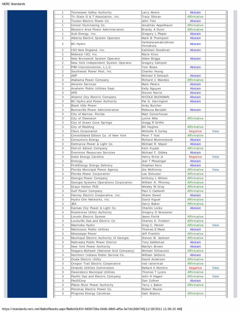
NERC Standards
https://standards.nerc.net/BallotResults.aspx?BallotGUID=b830728a-04d6-48b5-af5a-3e7cb1566745[11/18/2011 11:06:22 AM]
1 Tennessee Valley Authority Larry Akens Abstain1 Tri-State G & T Association, Inc. Tracy Sliman Affirmative1 Tucson Electric Power Co. John Tolo Abstain1 United Illuminating Co. Jonathan Appelbaum Affirmative1 Western Area Power Administration Brandy A Dunn Affirmative1 Xcel Energy, Inc. Gregory L Pieper Abstain2 Alberta Electric System Operator Mark B Thompson Abstain
2 BC Hydro VenkataramakrishnanVinnakota
Abstain
2 ISO New England, Inc. Kathleen Goodman Abstain2 Midwest ISO, Inc. Marie Knox2 New Brunswick System Operator Alden Briggs Abstain2 New York Independent System Operator Gregory Campoli2 PJM Interconnection, L.L.C. Tom Bowe Abstain2 Southwest Power Pool, Inc. Charles Yeung3 AEP Michael E Deloach Abstain3 Alabama Power Company Richard J. Mandes Affirmative3 Ameren Services Mark Peters Abstain3 Anaheim Public Utilities Dept. Kelly Nguyen Abstain3 APS Steven Norris Abstain3 Atlantic City Electric Company NICOLE BUCKMAN Abstain3 BC Hydro and Power Authority Pat G. Harrington Abstain3 Black Hills Power Andy Butcher3 Bonneville Power Administration Rebecca Berdahl Abstain3 City of Bartow, Florida Matt Culverhouse3 City of Clewiston Lynne Mila Affirmative3 City of Green Cove Springs Gregg R Griffin3 City of Redding Bill Hughes Affirmative3 Cleco Corporation Michelle A Corley Negative View3 Consolidated Edison Co. of New York Peter T Yost Affirmative3 Consumers Energy Richard Blumenstock Abstain3 Delmarva Power & Light Co. Michael R. Mayer Abstain3 Detroit Edison Company Kent Kujala Affirmative3 Dominion Resources Services Michael F. Gildea Abstain3 Duke Energy Carolina Henry Ernst-Jr Negative View3 Entergy Joel T Plessinger Abstain3 FirstEnergy Energy Delivery Stephan Kern Abstain3 Florida Municipal Power Agency Joe McKinney Affirmative View3 Florida Power Corporation Lee Schuster Affirmative3 Georgia Power Company Anthony L Wilson Affirmative3 Georgia Systems Operations Corporation William N. Phinney Affirmative3 Grays Harbor PUD Wesley W Gray Affirmative3 Gulf Power Company Paul C Caldwell Affirmative3 Harney Electric Cooperative, Inc. Shane Sweet Abstain3 Hydro One Networks, Inc. David Kiguel Affirmative3 JEA Garry Baker Affirmative3 Kansas City Power & Light Co. Charles Locke Abstain3 Kissimmee Utility Authority Gregory D Woessner3 Lincoln Electric System Jason Fortik Affirmative3 Louisville Gas and Electric Co. Charles A. Freibert Affirmative3 Manitoba Hydro Greg C. Parent Affirmative View3 Manitowoc Public Utilities Thomas E Reed Abstain3 Mississippi Power Jeff Franklin Affirmative3 Municipal Electric Authority of Georgia Steven M. Jackson Affirmative3 Nebraska Public Power District Tony Eddleman Abstain3 New York Power Authority Marilyn Brown Abstain3 Niagara Mohawk (National Grid Company) Michael Schiavone Affirmative3 Northern Indiana Public Service Co. William SeDoris Abstain3 Ocala Electric Utility David Anderson Affirmative3 Oregon Trail Electric Cooperative ned ratterman Affirmative3 Orlando Utilities Commission Ballard K Mutters Negative View3 Owensboro Municipal Utilities Thomas T Lyons Affirmative3 Pacific Gas and Electric Company John H Hagen Affirmative View3 PacifiCorp Dan Zollner Abstain3 Platte River Power Authority Terry L Baker Affirmative3 Potomac Electric Power Co. Robert Reuter3 Progress Energy Carolinas Sam Waters Affirmative
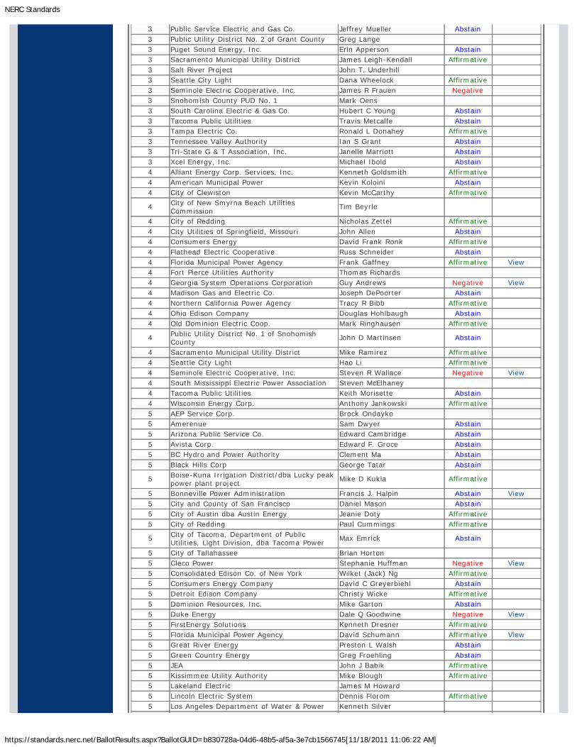
NERC Standards
https://standards.nerc.net/BallotResults.aspx?BallotGUID=b830728a-04d6-48b5-af5a-3e7cb1566745[11/18/2011 11:06:22 AM]
3 Public Service Electric and Gas Co. Jeffrey Mueller Abstain3 Public Utility District No. 2 of Grant County Greg Lange3 Puget Sound Energy, Inc. Erin Apperson Abstain3 Sacramento Municipal Utility District James Leigh-Kendall Affirmative3 Salt River Project John T. Underhill3 Seattle City Light Dana Wheelock Affirmative3 Seminole Electric Cooperative, Inc. James R Frauen Negative3 Snohomish County PUD No. 1 Mark Oens3 South Carolina Electric & Gas Co. Hubert C Young Abstain3 Tacoma Public Utilities Travis Metcalfe Abstain3 Tampa Electric Co. Ronald L Donahey Affirmative3 Tennessee Valley Authority Ian S Grant Abstain3 Tri-State G & T Association, Inc. Janelle Marriott Abstain3 Xcel Energy, Inc. Michael Ibold Abstain4 Alliant Energy Corp. Services, Inc. Kenneth Goldsmith Affirmative4 American Municipal Power Kevin Koloini Abstain4 City of Clewiston Kevin McCarthy Affirmative
4 City of New Smyrna Beach UtilitiesCommission
Tim Beyrle
4 City of Redding Nicholas Zettel Affirmative4 City Utilities of Springfield, Missouri John Allen Abstain4 Consumers Energy David Frank Ronk Affirmative4 Flathead Electric Cooperative Russ Schneider Abstain4 Florida Municipal Power Agency Frank Gaffney Affirmative View4 Fort Pierce Utilities Authority Thomas Richards4 Georgia System Operations Corporation Guy Andrews Negative View4 Madison Gas and Electric Co. Joseph DePoorter Abstain4 Northern California Power Agency Tracy R Bibb Affirmative4 Ohio Edison Company Douglas Hohlbaugh Abstain4 Old Dominion Electric Coop. Mark Ringhausen Affirmative
4 Public Utility District No. 1 of SnohomishCounty
John D Martinsen Abstain
4 Sacramento Municipal Utility District Mike Ramirez Affirmative4 Seattle City Light Hao Li Affirmative4 Seminole Electric Cooperative, Inc. Steven R Wallace Negative View4 South Mississippi Electric Power Association Steven McElhaney4 Tacoma Public Utilities Keith Morisette Abstain4 Wisconsin Energy Corp. Anthony Jankowski Affirmative5 AEP Service Corp. Brock Ondayko5 Amerenue Sam Dwyer Abstain5 Arizona Public Service Co. Edward Cambridge Abstain5 Avista Corp. Edward F. Groce Abstain5 BC Hydro and Power Authority Clement Ma Abstain5 Black Hills Corp George Tatar Abstain
5 Boise-Kuna Irrigation District/dba Lucky peakpower plant project
Mike D Kukla Affirmative
5 Bonneville Power Administration Francis J. Halpin Abstain View5 City and County of San Francisco Daniel Mason Abstain5 City of Austin dba Austin Energy Jeanie Doty Affirmative5 City of Redding Paul Cummings Affirmative
5 City of Tacoma, Department of PublicUtilities, Light Division, dba Tacoma Power
Max Emrick Abstain
5 City of Tallahassee Brian Horton5 Cleco Power Stephanie Huffman Negative View5 Consolidated Edison Co. of New York Wilket (Jack) Ng Affirmative5 Consumers Energy Company David C Greyerbiehl Abstain5 Detroit Edison Company Christy Wicke Affirmative5 Dominion Resources, Inc. Mike Garton Abstain5 Duke Energy Dale Q Goodwine Negative View5 FirstEnergy Solutions Kenneth Dresner Affirmative5 Florida Municipal Power Agency David Schumann Affirmative View5 Great River Energy Preston L Walsh Abstain5 Green Country Energy Greg Froehling Abstain5 JEA John J Babik Affirmative5 Kissimmee Utility Authority Mike Blough Affirmative5 Lakeland Electric James M Howard5 Lincoln Electric System Dennis Florom Affirmative5 Los Angeles Department of Water & Power Kenneth Silver
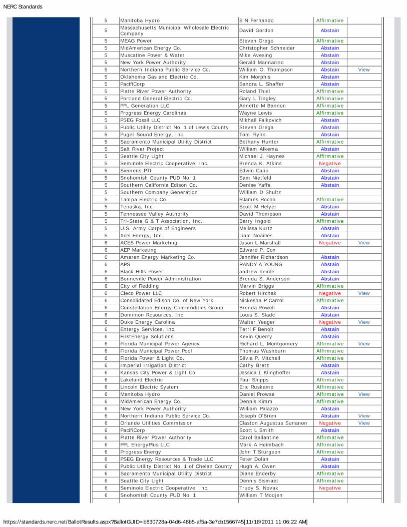
NERC Standards
https://standards.nerc.net/BallotResults.aspx?BallotGUID=b830728a-04d6-48b5-af5a-3e7cb1566745[11/18/2011 11:06:22 AM]
5 Manitoba Hydro S N Fernando Affirmative
5 Massachusetts Municipal Wholesale ElectricCompany
David Gordon Abstain
5 MEAG Power Steven Grego Affirmative5 MidAmerican Energy Co. Christopher Schneider Abstain5 Muscatine Power & Water Mike Avesing Abstain5 New York Power Authority Gerald Mannarino Abstain5 Northern Indiana Public Service Co. William O. Thompson Abstain View5 Oklahoma Gas and Electric Co. Kim Morphis Abstain5 PacifiCorp Sandra L. Shaffer Abstain5 Platte River Power Authority Roland Thiel Affirmative5 Portland General Electric Co. Gary L Tingley Affirmative5 PPL Generation LLC Annette M Bannon Affirmative5 Progress Energy Carolinas Wayne Lewis Affirmative5 PSEG Fossil LLC Mikhail Falkovich Abstain5 Public Utility District No. 1 of Lewis County Steven Grega Abstain5 Puget Sound Energy, Inc. Tom Flynn Abstain5 Sacramento Municipal Utility District Bethany Hunter Affirmative5 Salt River Project William Alkema Abstain5 Seattle City Light Michael J. Haynes Affirmative5 Seminole Electric Cooperative, Inc. Brenda K. Atkins Negative5 Siemens PTI Edwin Cano Abstain5 Snohomish County PUD No. 1 Sam Nietfeld Abstain5 Southern California Edison Co. Denise Yaffe Abstain5 Southern Company Generation William D Shultz5 Tampa Electric Co. RJames Rocha Affirmative5 Tenaska, Inc. Scott M Helyer Abstain5 Tennessee Valley Authority David Thompson Abstain5 Tri-State G & T Association, Inc. Barry Ingold Affirmative5 U.S. Army Corps of Engineers Melissa Kurtz Abstain5 Xcel Energy, Inc. Liam Noailles Abstain6 ACES Power Marketing Jason L Marshall Negative View6 AEP Marketing Edward P. Cox6 Ameren Energy Marketing Co. Jennifer Richardson Abstain6 APS RANDY A YOUNG Abstain6 Black Hills Power andrew heinle Abstain6 Bonneville Power Administration Brenda S. Anderson Abstain6 City of Redding Marvin Briggs Affirmative6 Cleco Power LLC Robert Hirchak Negative View6 Consolidated Edison Co. of New York Nickesha P Carrol Affirmative6 Constellation Energy Commodities Group Brenda Powell Abstain6 Dominion Resources, Inc. Louis S. Slade Abstain6 Duke Energy Carolina Walter Yeager Negative View6 Entergy Services, Inc. Terri F Benoit Abstain6 FirstEnergy Solutions Kevin Querry Abstain6 Florida Municipal Power Agency Richard L. Montgomery Affirmative View6 Florida Municipal Power Pool Thomas Washburn Affirmative6 Florida Power & Light Co. Silvia P. Mitchell Affirmative6 Imperial Irrigation District Cathy Bretz Abstain6 Kansas City Power & Light Co. Jessica L Klinghoffer Abstain6 Lakeland Electric Paul Shipps Affirmative6 Lincoln Electric System Eric Ruskamp Affirmative6 Manitoba Hydro Daniel Prowse Affirmative View6 MidAmerican Energy Co. Dennis Kimm Affirmative6 New York Power Authority William Palazzo Abstain6 Northern Indiana Public Service Co. Joseph O'Brien Abstain View6 Orlando Utilities Commission Claston Augustus Sunanon Negative View6 PacifiCorp Scott L Smith Abstain6 Platte River Power Authority Carol Ballantine Affirmative6 PPL EnergyPlus LLC Mark A Heimbach Affirmative6 Progress Energy John T Sturgeon Affirmative6 PSEG Energy Resources & Trade LLC Peter Dolan Abstain6 Public Utility District No. 1 of Chelan County Hugh A. Owen Abstain6 Sacramento Municipal Utility District Diane Enderby Affirmative6 Seattle City Light Dennis Sismaet Affirmative6 Seminole Electric Cooperative, Inc. Trudy S. Novak Negative6 Snohomish County PUD No. 1 William T Moojen

NERC Standards
https://standards.nerc.net/BallotResults.aspx?BallotGUID=b830728a-04d6-48b5-af5a-3e7cb1566745[11/18/2011 11:06:22 AM]
6 South California Edison Company Lujuanna Medina
6 Southern Company Generation and EnergyMarketing
John J. Ciza Affirmative
6 Tacoma Public Utilities Michael C Hill Abstain6 Tampa Electric Co. Benjamin F Smith II Affirmative6 Tennessee Valley Authority Marjorie S. Parsons Abstain
6 Western Area Power Administration - UGPMarketing
Peter H Kinney Affirmative
6 Xcel Energy, Inc. David F. Lemmons Abstain8 Roger C Zaklukiewicz Affirmative8 Edward C Stein Affirmative8 James A Maenner8 Merle Ashton8 JDRJC Associates Jim Cyrulewski Affirmative8 Utility Services, Inc. Brian Evans-Mongeon8 Volkmann Consulting, Inc. Terry Volkmann Affirmative9 California Energy Commission William M Chamberlain Abstain
9 Commonwealth of Massachusetts Departmentof Public Utilities
Donald Nelson Affirmative
9 Public Utilities Commission of Ohio Klaus Lambeck10 Florida Reliability Coordinating Council Linda Campbell Abstain10 Midwest Reliability Organization James D Burley10 New York State Reliability Council Alan Adamson Affirmative10 Northeast Power Coordinating Council, Inc. Guy V. Zito Affirmative10 ReliabilityFirst Corporation Anthony E Jablonski Affirmative View10 SERC Reliability Corporation Carter B. Edge Affirmative10 Western Electricity Coordinating Council Steven L. Rueckert Abstain
Legal and Privacy : 609.452.8060 voice : 609.452.9550 fax : 116-390 Village Boulevard : Princeton, NJ 08540-5721Washington Office: 1120 G Street, N.W. : Suite 990 : Washington, DC 20005-3801
Copyright © 2010 by the North American Electric Reliability Corporation. : All rights reserved.A New Jersey Nonprofit Corporation
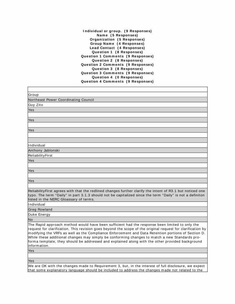
Individual or group. (9 Responses) Name (5 Responses)
Organization (5 Responses) Group Name (4 Responses) Lead Contact (4 Responses) Question 1 (8 Responses)
Question 1 Comments (9 Responses) Question 2 (8 Responses)
Question 2 Comments (9 Responses) Question 3 (8 Responses)
Question 3 Comments (9 Responses) Question 4 (0 Responses)
Question 4 Comments (9 Responses)
Group Northeast Power Coordinating Council Guy Zito Yes Yes Yes Individual Anthony Jablonski ReliabilityFirst Yes Yes Yes ReliabilityFirst agrees with that the redlined changes further clarify the intent of R3.1 but noticed one typo. The term “Daily” in part 3.1.3 should not be capitalized since the term “Daily” is not a definiton listed in the NERC Gloassary of terms. Individual Greg Rowland Duke Energy No The Rapid approach method would have been sufficient had the response been limited to only the request for clarification. This revision goes beyond the scope of the original request for clarification by modifying the VRFs as well as the Compliance Enforcement and Data Retention portions of Section D. While these additional changes may simply be conforming changes to match a new Standards pro-forma template, they should be addressed and explained along with the other provided background information. Yes Yes We are OK with the changes made to Requirement 3, but, in the interest of full disclosure, we expect that some explanatory language should be included to address the changes made not related to the
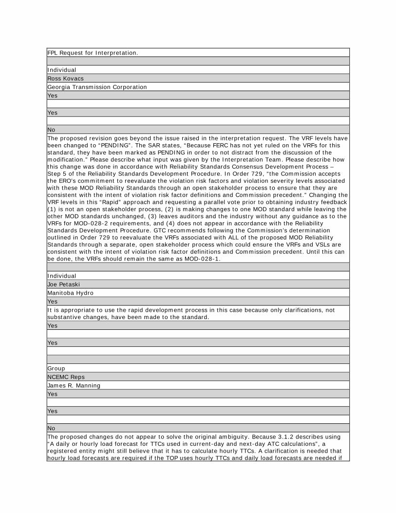
FPL Request for Interpretation. Individual Ross Kovacs Georgia Transmission Corporation Yes Yes No The proposed revision goes beyond the issue raised in the interpretation request. The VRF levels have been changed to “PENDING”. The SAR states, “Because FERC has not yet ruled on the VRFs for this standard, they have been marked as PENDING in order to not distract from the discussion of the modification.” Please describe what input was given by the Interpretation Team. Please describe how this change was done in accordance with Reliability Standards Consensus Development Process – Step 5 of the Reliability Standards Development Procedure. In Order 729, “the Commission accepts the ERO’s commitment to reevaluate the violation risk factors and violation severity levels associated with these MOD Reliability Standards through an open stakeholder process to ensure that they are consistent with the intent of violation risk factor definitions and Commission precedent.” Changing the VRF levels in this “Rapid” approach and requesting a parallel vote prior to obtaining industry feedback (1) is not an open stakeholder process, (2) is making changes to one MOD standard while leaving the other MOD standards unchanged, (3) leaves auditors and the industry without any guidance as to the VRFs for MOD-028-2 requirements, and (4) does not appear in accordance with the Reliability Standards Development Procedure. GTC recommends following the Commission’s determination outlined in Order 729 to reevaluate the VRFs associated with ALL of the proposed MOD Reliability Standards through a separate, open stakeholder process which could ensure the VRFs and VSLs are consistent with the intent of violation risk factor definitions and Commission precedent. Until this can be done, the VRFs should remain the same as MOD-028-1. Individual Joe Petaski Manitoba Hydro Yes It is appropriate to use the rapid development process in this case because only clarifications, not substantive changes, have been made to the standard. Yes Yes Group NCEMC Reps James R. Manning Yes Yes No The proposed changes do not appear to solve the original ambiguity. Because 3.1.2 describes using “A daily or hourly load forecast for TTCs used in current-day and next-day ATC calculations”, a registered entity might still believe that it has to calculate hourly TTCs. A clarification is needed that hourly load forecasts are required if the TOP uses hourly TTCs and daily load forecasts are needed if
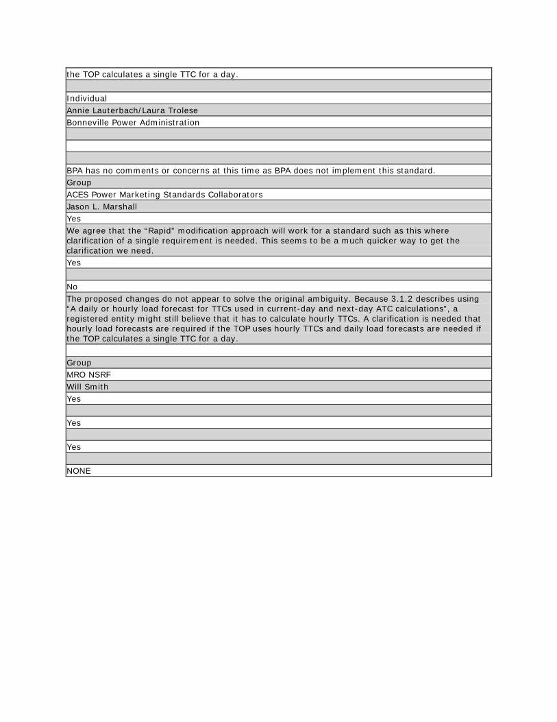
the TOP calculates a single TTC for a day. Individual Annie Lauterbach/Laura Trolese Bonneville Power Administration BPA has no comments or concerns at this time as BPA does not implement this standard. Group ACES Power Marketing Standards Collaborators Jason L. Marshall Yes We agree that the “Rapid” modification approach will work for a standard such as this where clarification of a single requirement is needed. This seems to be a much quicker way to get the clarification we need. Yes No The proposed changes do not appear to solve the original ambiguity. Because 3.1.2 describes using “A daily or hourly load forecast for TTCs used in current-day and next-day ATC calculations”, a registered entity might still believe that it has to calculate hourly TTCs. A clarification is needed that hourly load forecasts are required if the TOP uses hourly TTCs and daily load forecasts are needed if the TOP calculates a single TTC for a day. Group MRO NSRF Will Smith Yes Yes Yes NONE

Consideration of Comments Project 2011-INT-01 – Interpretation of MOD-028 R3.1 for FPL The 2011-INT-01 – Interpretation Drafting Team thanks all commenters who submitted comments on the SAR and draft MOD-028-2 standard (Area Interchange Methodology). These standards were posted for a 45-day public comment period from October 3, 2011 through November 16, 2011. Stakeholders were asked to provide feedback on the standards and associated documents through a special electronic comment form. There were 9 sets of comments, including comments from 51 different people from approximately 43 companies representing all of the 10 Industry Segments as shown in the table on the following pages. Ballots indicated general support with a quorum of 88.05% and an affirmative vote of 85.53%. Summary Consideration: Most comments indicated the use of a “Rapid” approach to clarify the standard is acceptable. Some comments expressed concern regarding the updates to the compliance sections of the standard. These changes were administrative in nature and do not indicate changes to the stakeholder-approved requirements of the standard.
The majority of the comments received indicate the issue raised in the interpretation request has been satisfactorily resolved.
Two comments questioned if the intent of the standard was to go beyond the changes written, and to require an hourly load forecast for use in an hourly TTC and a daily load forecast for use in a daily TTC. The intent of the standard is to allow for either daily or hourly load forecasts in the specified situation. In other words, a “daily” load forecast is the minimum acceptable performance, but an “hourly” forecast is also acceptable to meet the requirement.
Specifically, some commenters questioned the data retention section of the standard and how it should be applied. Data should be retained as stated in the original standard. The added language gives instruction for when the retention period is shorter than the time since the last audit. According to Section 3.1.4.2 of Appendix 4c to NERC’s Rules of Procedure, an entity is responsible for compliance for the entire time since the last audit and will be expected to demonstrate its compliance. The paragraph that was added to the Data Retention section of the standard was written by NERC Legal staff to notify entities of this responsibility and is not specific to MOD-028-2; this paragraph is being added to all standards as they are revised.
One commenter identified a capitalization error in R3.1, which has been corrected as noted so that the term “daily” is not capitalized. Additionally, the capitalization of the word “monthly” was removed, and a formatting error corrected. No other changes were made to the standard.

2011-INT-01 MOD-028 Consideration of Comments 2
All comments submitted may be reviewed in their original format on the standard’s project page:
http://www.nerc.com/filez/standards/2011-INT-01_Interpretation_MOD-028-1_FPL.html
If you feel that your comment has been overlooked, please let us know immediately. Our goal is to give every comment serious consideration in this process! If you feel there has been an error or omission, you can contact the Vice President and Director of Standards, Herb Schrayshuen, at 404-446-2560 or at [email protected]. In addition, there is a NERC Reliability Standards Appeals Process.1
1 The appeals process is in the Reliability Standards Development Procedures: http://www.nerc.com/standards/newstandardsprocess.html.
2011-INT-01 MOD-028 Consideration of Comments 3
Index to Questions, Comments, and Responses
1. Do you agree with the use of this “Rapid” approach to clarify the standard, rather than clarifying the standard through an Interpretation? If No, please explain your concerns ............................ 7
2. Does the language in the SAR adequately represent the issue raised in the interpretation request?
If No, please provide your suggestions to modify the SAR. ..................................................... 9 3. Does the proposed revision resolve the issue raised in the interpretation request? If No, please
provide your suggestions to modify the standard. ............................................................... 10 4. If you have any other comments on the SAR or on the proposed Standard that you have not
provided above, please provide them here. ....................................................................... 14
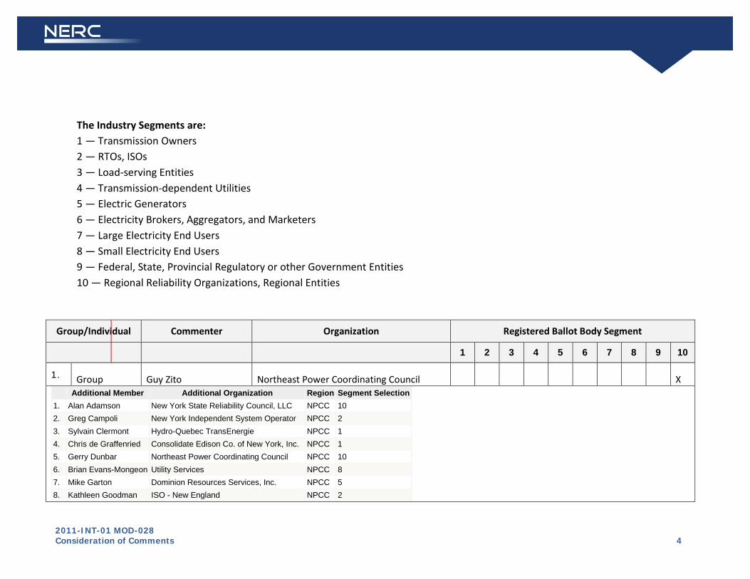
2011-INT-01 MOD-028 Consideration of Comments 4
The Industry Segments are: 1 — Transmission Owners 2 — RTOs, ISOs 3 — Load-serving Entities 4 — Transmission-dependent Utilities 5 — Electric Generators 6 — Electricity Brokers, Aggregators, and Marketers 7 — Large Electricity End Users 8 — Small Electricity End Users 9 — Federal, State, Provincial Regulatory or other Government Entities 10 — Regional Reliability Organizations, Regional Entities
Group/Individual Commenter Organization Registered Ballot Body Segment
1 2 3 4 5 6 7 8 9 10
1. Group Guy Zito Northeast Power Coordinating Council X Additional Member Additional Organization Region Segment Selection
1. Alan Adamson New York State Reliability Council, LLC NPCC 10 2. Greg Campoli New York Independent System Operator NPCC 2 3. Sylvain Clermont Hydro-Quebec TransEnergie NPCC 1 4. Chris de Graffenried Consolidate Edison Co. of New York, Inc. NPCC 1 5. Gerry Dunbar Northeast Power Coordinating Council NPCC 10 6. Brian Evans-Mongeon Utility Services NPCC 8 7. Mike Garton Dominion Resources Services, Inc. NPCC 5 8. Kathleen Goodman ISO - New England NPCC 2
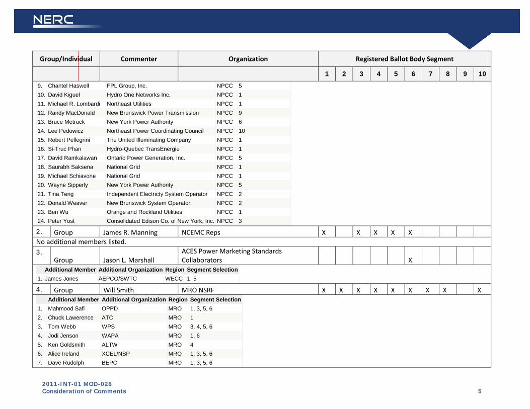
2011-INT-01 MOD-028 Consideration of Comments 5
Group/Individual Commenter Organization Registered Ballot Body Segment
1 2 3 4 5 6 7 8 9 10
9. Chantel Haswell FPL Group, Inc. NPCC 5 10. David Kiguel Hydro One Networks Inc. NPCC 1 11. Michael R. Lombardi Northeast Utilities NPCC 1 12. Randy MacDonald New Brunswick Power Transmission NPCC 9 13. Bruce Metruck New York Power Authority NPCC 6 14. Lee Pedowicz Northeast Power Coordinating Council NPCC 10 15. Robert Pellegrini The United Illuminating Company NPCC 1 16. Si-Truc Phan Hydro-Quebec TransEnergie NPCC 1 17. David Ramkalawan Ontario Power Generation, Inc. NPCC 5 18. Saurabh Saksena National Grid NPCC 1 19. Michael Schiavone National Grid NPCC 1 20. Wayne Sipperly New York Power Authority NPCC 5 21. Tina Teng Independent Electricty System Operator NPCC 2 22. Donald Weaver New Brunswick System Operator NPCC 2 23. Ben Wu Orange and Rockland Utilities NPCC 1 24. Peter Yost Consolidated Edison Co. of New York, Inc. NPCC 3
2. Group James R. Manning NCEMC Reps X X X X X No additional members listed. 3.
Group Jason L. Marshall ACES Power Marketing Standards Collaborators X
Additional Member Additional Organization Region Segment Selection 1. James Jones AEPCO/SWTC WECC 1, 5
4. Group Will Smith MRO NSRF X X X X X X X X X Additional Member Additional Organization Region Segment Selection
1. Mahmood Safi OPPD MRO 1, 3, 5, 6 2. Chuck Lawerence ATC MRO 1 3. Tom Webb WPS MRO 3, 4, 5, 6 4. Jodi Jenson WAPA MRO 1, 6 5. Ken Goldsmith ALTW MRO 4 6. Alice Ireland XCEL/NSP MRO 1, 3, 5, 6 7. Dave Rudolph BEPC MRO 1, 3, 5, 6
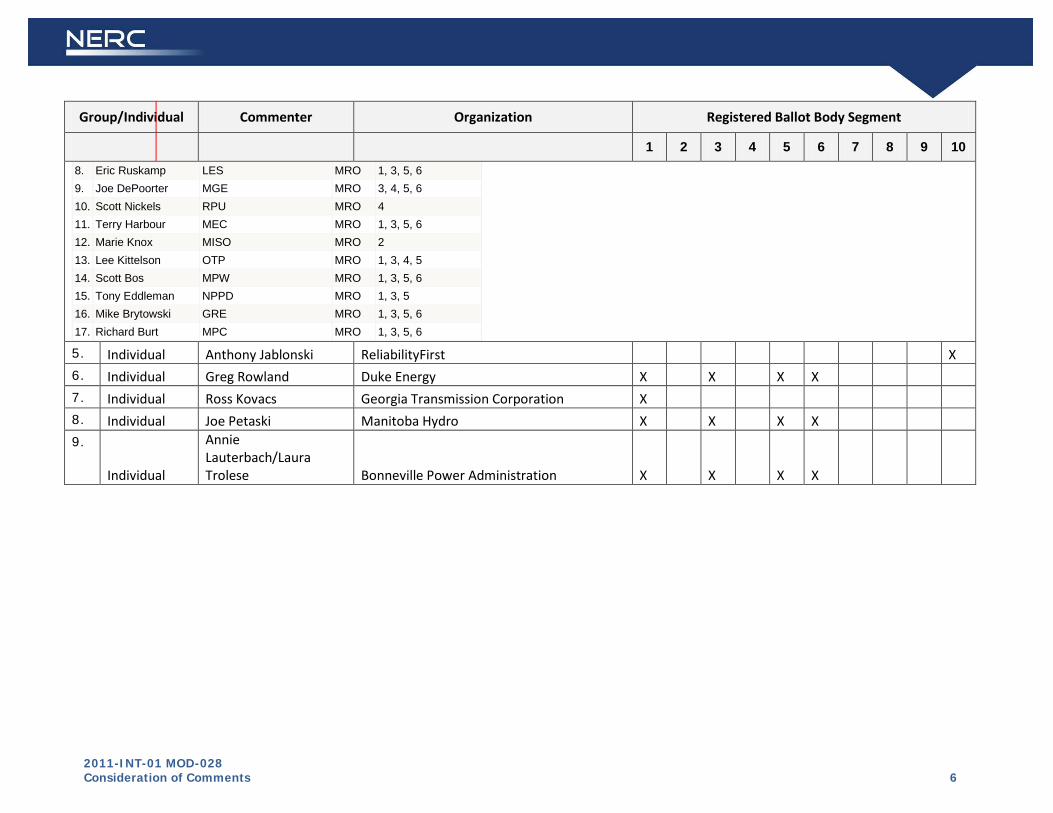
2011-INT-01 MOD-028 Consideration of Comments 6
Group/Individual Commenter Organization Registered Ballot Body Segment
1 2 3 4 5 6 7 8 9 10
8. Eric Ruskamp LES MRO 1, 3, 5, 6 9. Joe DePoorter MGE MRO 3, 4, 5, 6 10. Scott Nickels RPU MRO 4 11. Terry Harbour MEC MRO 1, 3, 5, 6 12. Marie Knox MISO MRO 2 13. Lee Kittelson OTP MRO 1, 3, 4, 5 14. Scott Bos MPW MRO 1, 3, 5, 6 15. Tony Eddleman NPPD MRO 1, 3, 5 16. Mike Brytowski GRE MRO 1, 3, 5, 6 17. Richard Burt MPC MRO 1, 3, 5, 6
5. Individual Anthony Jablonski ReliabilityFirst X 6. Individual Greg Rowland Duke Energy X X X X 7. Individual Ross Kovacs Georgia Transmission Corporation X 8. Individual Joe Petaski Manitoba Hydro X X X X 9.
Individual
Annie Lauterbach/Laura Trolese Bonneville Power Administration X X X X

2011-INT-01 MOD-028 Consideration of Comments 7
1.
Do you agree with the use of this “Rapid” approach to clarify the standard, rather than clarifying the standard through an Interpretation? If No, please explain your concerns
Summary Consideration: Most comments indicated the use of a “Rapid” approach to clarify the standard is acceptable. Some comments expressed concern regarding the updates to the compliance sections of the standard; however, these changes were administrative in nature related to language used to enforce compliance, and do not indicate changes to the stakeholder-approved requirements of the standard.
Organization Yes or No Question 1 Comment
Northeast Power Coordinating Council
Yes
NCEMC Reps Yes
ACES Power Marketing Standards Collaborators
Yes We agree that the “Rapid” modification approach will work for a standard such as this where clarification of a single requirement is needed. This seems to be a much quicker way to get the clarification we need.
Response: The Drafting Team thanks you for your comment.
MRO NSRF Yes
ReliabilityFirst Yes
Georgia Transmission Corporation Yes
Manitoba Hydro Yes It is appropriate to use the rapid development process in this case because only clarifications, not substantive changes, have been made to the standard.
Response: The Drafting Team thanks you for your comment.
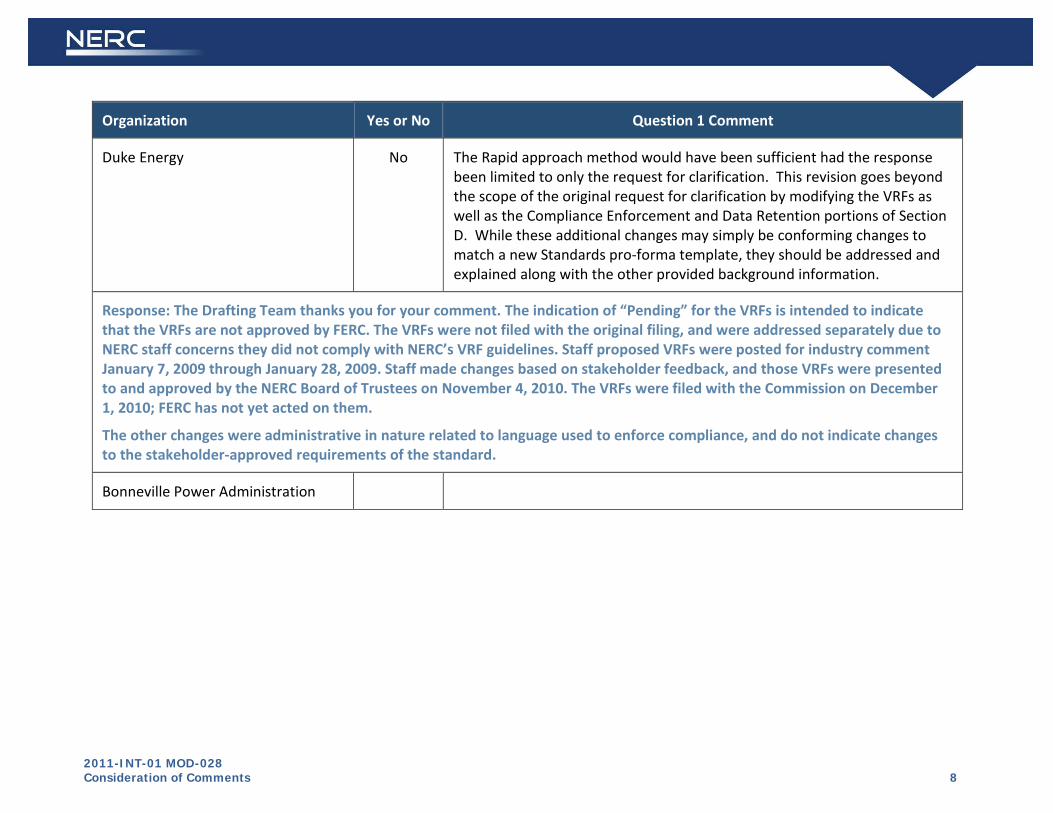
2011-INT-01 MOD-028 Consideration of Comments 8
Organization Yes or No Question 1 Comment
Duke Energy No The Rapid approach method would have been sufficient had the response been limited to only the request for clarification. This revision goes beyond the scope of the original request for clarification by modifying the VRFs as well as the Compliance Enforcement and Data Retention portions of Section D. While these additional changes may simply be conforming changes to match a new Standards pro-forma template, they should be addressed and explained along with the other provided background information.
Response: The Drafting Team thanks you for your comment. The indication of “Pending” for the VRFs is intended to indicate that the VRFs are not approved by FERC. The VRFs were not filed with the original filing, and were addressed separately due to NERC staff concerns they did not comply with NERC’s VRF guidelines. Staff proposed VRFs were posted for industry comment January 7, 2009 through January 28, 2009. Staff made changes based on stakeholder feedback, and those VRFs were presented to and approved by the NERC Board of Trustees on November 4, 2010. The VRFs were filed with the Commission on December 1, 2010; FERC has not yet acted on them.
The other changes were administrative in nature related to language used to enforce compliance, and do not indicate changes to the stakeholder-approved requirements of the standard.
Bonneville Power Administration

2011-INT-01 MOD-028 Consideration of Comments 9
2.
Does the language in the SAR adequately represent the issue raised in the interpretation request? If No, please provide your suggestions to modify the SAR.
Summary Consideration: The comments received indicate the language in the SAR adequately represents the issue raised in the interpretation request.
Organization Yes or No Question 2 Comment
Northeast Power Coordinating Council
Yes
NCEMC Reps Yes
ACES Power Marketing Standards Collaborators
Yes
MRO NSRF Yes
ReliabilityFirst Yes
Duke Energy Yes
Georgia Transmission Corporation
Yes
Manitoba Hydro Yes
Bonneville Power Administration
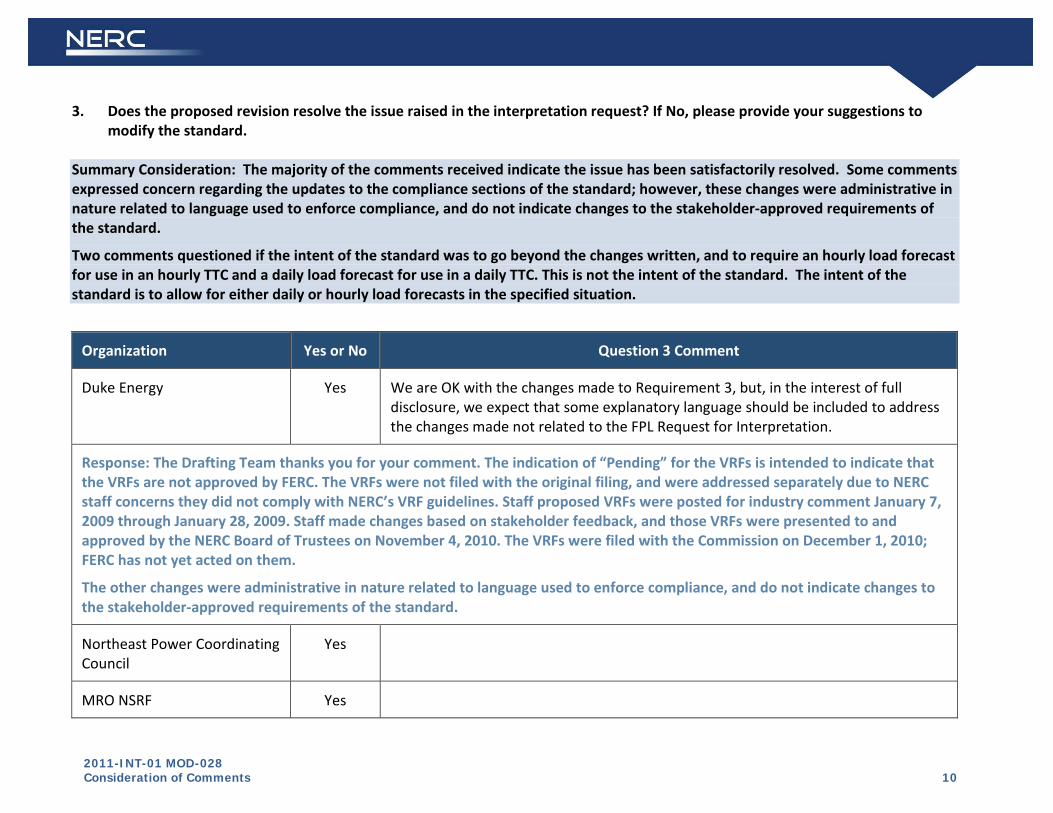
2011-INT-01 MOD-028 Consideration of Comments 10
3. Does the proposed revision resolve the issue raised in the interpretation request? If No, please provide your suggestions to modify the standard.
Summary Consideration: The majority of the comments received indicate the issue has been satisfactorily resolved. Some comments expressed concern regarding the updates to the compliance sections of the standard; however, these changes were administrative in nature related to language used to enforce compliance, and do not indicate changes to the stakeholder-approved requirements of the standard.
Two comments questioned if the intent of the standard was to go beyond the changes written, and to require an hourly load forecast for use in an hourly TTC and a daily load forecast for use in a daily TTC. This is not the intent of the standard. The intent of the standard is to allow for either daily or hourly load forecasts in the specified situation.
Organization Yes or No Question 3 Comment
Duke Energy Yes We are OK with the changes made to Requirement 3, but, in the interest of full disclosure, we expect that some explanatory language should be included to address the changes made not related to the FPL Request for Interpretation.
Response: The Drafting Team thanks you for your comment. The indication of “Pending” for the VRFs is intended to indicate that the VRFs are not approved by FERC. The VRFs were not filed with the original filing, and were addressed separately due to NERC staff concerns they did not comply with NERC’s VRF guidelines. Staff proposed VRFs were posted for industry comment January 7, 2009 through January 28, 2009. Staff made changes based on stakeholder feedback, and those VRFs were presented to and approved by the NERC Board of Trustees on November 4, 2010. The VRFs were filed with the Commission on December 1, 2010; FERC has not yet acted on them.
The other changes were administrative in nature related to language used to enforce compliance, and do not indicate changes to the stakeholder-approved requirements of the standard.
Northeast Power Coordinating Council
Yes
MRO NSRF Yes
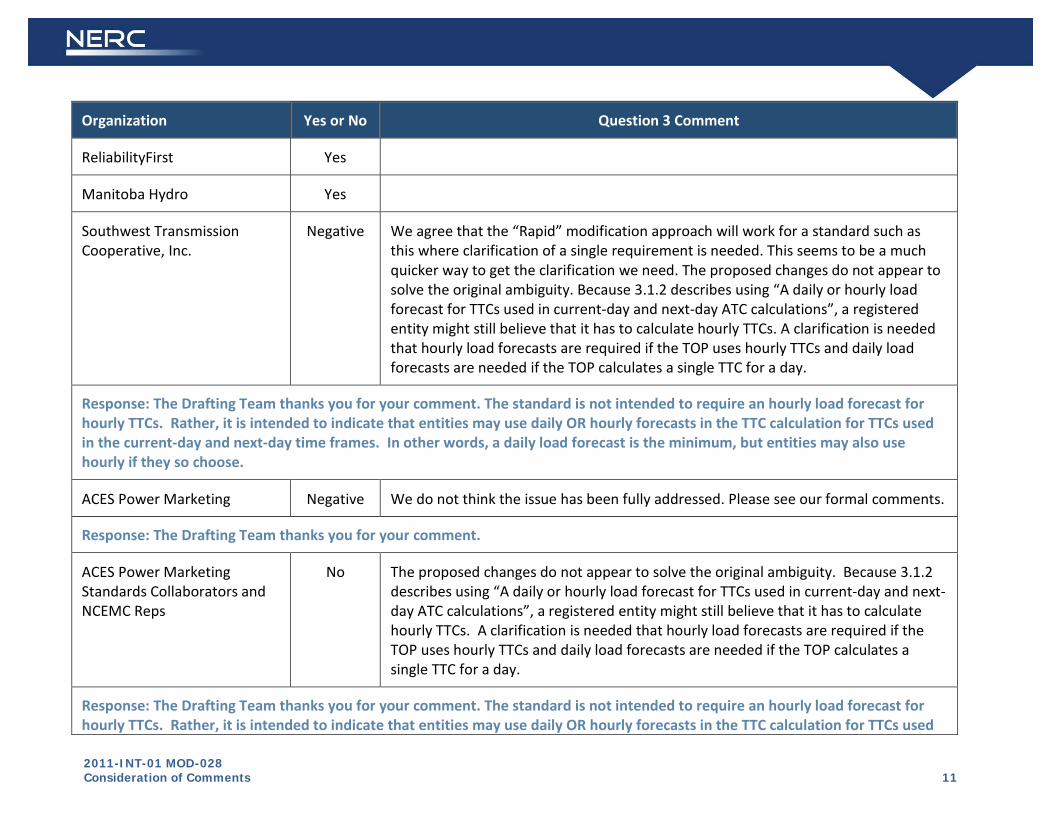
2011-INT-01 MOD-028 Consideration of Comments 11
Organization Yes or No Question 3 Comment
ReliabilityFirst Yes
Manitoba Hydro Yes
Southwest Transmission Cooperative, Inc.
Negative We agree that the “Rapid” modification approach will work for a standard such as this where clarification of a single requirement is needed. This seems to be a much quicker way to get the clarification we need. The proposed changes do not appear to solve the original ambiguity. Because 3.1.2 describes using “A daily or hourly load forecast for TTCs used in current-day and next-day ATC calculations”, a registered entity might still believe that it has to calculate hourly TTCs. A clarification is needed that hourly load forecasts are required if the TOP uses hourly TTCs and daily load forecasts are needed if the TOP calculates a single TTC for a day.
Response: The Drafting Team thanks you for your comment. The standard is not intended to require an hourly load forecast for hourly TTCs. Rather, it is intended to indicate that entities may use daily OR hourly forecasts in the TTC calculation for TTCs used in the current-day and next-day time frames. In other words, a daily load forecast is the minimum, but entities may also use hourly if they so choose.
ACES Power Marketing Negative We do not think the issue has been fully addressed. Please see our formal comments.
Response: The Drafting Team thanks you for your comment.
ACES Power Marketing Standards Collaborators and NCEMC Reps
No The proposed changes do not appear to solve the original ambiguity. Because 3.1.2 describes using “A daily or hourly load forecast for TTCs used in current-day and next-day ATC calculations”, a registered entity might still believe that it has to calculate hourly TTCs. A clarification is needed that hourly load forecasts are required if the TOP uses hourly TTCs and daily load forecasts are needed if the TOP calculates a single TTC for a day.
Response: The Drafting Team thanks you for your comment. The standard is not intended to require an hourly load forecast for hourly TTCs. Rather, it is intended to indicate that entities may use daily OR hourly forecasts in the TTC calculation for TTCs used

2011-INT-01 MOD-028 Consideration of Comments 12
Organization Yes or No Question 3 Comment
in the current-day and next-day time frames. In other words, a daily load forecast is the minimum, but entities may also use hourly if they so choose.
Georgia Transmission Corporation
No The proposed revision goes beyond the issue raised in the interpretation request. The VRF levels have been changed to “PENDING”. The SAR states, “Because FERC has not yet ruled on the VRFs for this standard, they have been marked as PENDING in order to not distract from the discussion of the modification.” Please describe what input was given by the Interpretation Team. Please describe how this change was done in accordance with Reliability Standards Consensus Development Process - Step 5 of the Reliability Standards Development Procedure. In Order 729, “the Commission accepts the ERO’s commitment to reevaluate the violation risk factors and violation severity levels associated with these MOD Reliability Standards through an open stakeholder process to ensure that they are consistent with the intent of violation risk factor definitions and Commission precedent.” Changing the VRF levels in this “Rapid” approach and requesting a parallel vote prior to obtaining industry feedback (1) is not an open stakeholder process, (2) is making changes to one MOD standard while leaving the other MOD standards unchanged, (3) leaves auditors and the industry without any guidance as to the VRFs for MOD-028-2 requirements, and (4) does not appear in accordance with the Reliability Standards Development Procedure. GTC recommends following the Commission’s determination outlined in Order 729 to reevaluate the VRFs associated with ALL of the proposed MOD Reliability Standards through a separate, open stakeholder process which could ensure the VRFs and VSLs are consistent with the intent of violation risk factor definitions and Commission precedent. Until this can be done, the VRFs should remain the same as MOD-028-1.

2011-INT-01 MOD-028 Consideration of Comments 13
Response: The Drafting Team thanks you for your comment. The indication of “Pending” for the VRFs is intended to indicate that the VRFs are not approved by FERC. The VRFs were not filed with the original filing, and were addressed separately due to NERC staff concerns that they did not comply with NERC’s VRF guidelines. Staff proposed VRFs were posted for industry comment January 7, 2009 through January 28, 2009. Staff made changes based on stakeholder feedback, and those VRFs were presented to and approved by the NERC Board of Trustees on November 4, 2010. The VRFs were filed with the Commission on December 1, 2010 (see http://www.nerc.com/files/Final_Final_VSL_filing_complete.pdf); FERC has not yet acted on them.
Bonneville Power Administration
4.

2011-INT-01 MOD-028 Consideration of Comments 14
If you have any other comments on the SAR or on the proposed Standard that you have not provided above, please provide them here.
Summary Consideration: Several commenters expressed concern regarding the updates to the compliance sections of the standard; however, these changes were administrative in nature related to language used to enforce compliance, and do not indicate changes to the stakeholder-approved requirements of the standard.
Specifically, some commenters questioned the data retention section of the standard and how it should be applied. Data should be retained as stated in the original standard. The added language gives instruction for when the retention period is shorter than the time since the last audit. An entity is responsible for compliance for the entire time since the last audit and will be expected to demonstrate its compliance. The paragraph that was added to the Data Retention section of the standard was written by NERC Legal staff to notify entities of this responsibility and is not specific to MOD-028-2; this paragraph is being added to all standards as they are revised.. This paragraph is not intended to mandate that entities retain data beyond the data retention periods specified, but entities should be prepared to provide some form of evidence to indicate the standard was complied with. Retaining data is one way (but not the only way) in which such compliance could be demonstrated.
For reference, the relevant text from Appendix 4C of NERC’s Rules of Procedure is included below:
3.1.4.2 Period Covered The Registered Entity’s data and information should show compliance with the Reliability Standards that are the subject of the Compliance Audit for the period beginning with the day after the prior audit by the Compliance Enforcement Authority ended (or the later of June 18, 2007 or the Registered Entity’s date of registration if the Registered Entity has not previously been subject to a Compliance Audit), and ending with the End Date for the Compliance Audit. However, if another Compliance Monitoring and Enforcement process has been conducted with respect to the Registered Entity subsequent to the date that would otherwise be the start of the period, the period covered by the Compliance Audit may, in the Regional Entity’s discretion, begin with the completion of that Compliance Monitoring and Enforcement process for those Reliability Standards requirements that were the subject of the Compliance Monitoring and Enforcement process. The End Date will be stated in the Compliance Enforcement Authority’s notification of the Compliance Audit issued to the Registered Entity pursuant to Section 3.1.1. The Registered Entity will be expected to demonstrate compliance for the entire period described above. However, if a Reliability Standard specifies a document retention period that does not cover the entire period described above, the Registered Entity will not be found in noncompliance solely on the basis of the lack of specific information that has rightfully not been retained based on the retention period specified in the Reliability Standard. However, in such cases, the Compliance Enforcement Authority will require the Registered Entity to demonstrate compliance through other means.
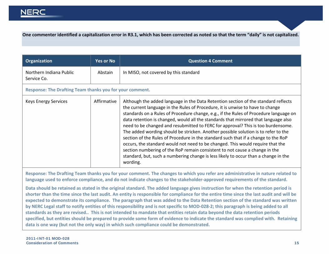
2011-INT-01 MOD-028 Consideration of Comments 15
One commenter identified a capitalization error in R3.1, which has been corrected as noted so that the term “daily” is not capitalized.
Organization Yes or No Question 4 Comment
Northern Indiana Public Service Co.
Abstain In MISO, not covered by this standard
Response: The Drafting Team thanks you for your comment.
Keys Energy Services Affirmative Although the added language in the Data Retention section of the standard reflects the current language in the Rules of Procedure, it is unwise to have to change standards on a Rules of Procedure change, e.g., if the Rules of Procedure language on data retention is changed, would all the standards that mirrored that language also need to be changed and resubmitted to FERC for approval? This is too burdensome. The added wording should be stricken. Another possible solution is to refer to the section of the Rules of Procedure in the standard such that if a change to the RoP occurs, the standard would not need to be changed. This would require that the section numbering of the RoP remain consistent to not cause a change in the standard, but, such a numbering change is less likely to occur than a change in the wording.
Response: The Drafting Team thanks you for your comment. The changes to which you refer are administrative in nature related to language used to enforce compliance, and do not indicate changes to the stakeholder-approved requirements of the standard.
Data should be retained as stated in the original standard. The added language gives instruction for when the retention period is shorter than the time since the last audit. An entity is responsible for compliance for the entire time since the last audit and will be expected to demonstrate its compliance. The paragraph that was added to the Data Retention section of the standard was written by NERC Legal staff to notify entities of this responsibility and is not specific to MOD-028-2; this paragraph is being added to all standards as they are revised.. This is not intended to mandate that entities retain data beyond the data retention periods specified, but entities should be prepared to provide some form of evidence to indicate the standard was complied with. Retaining data is one way (but not the only way) in which such compliance could be demonstrated.
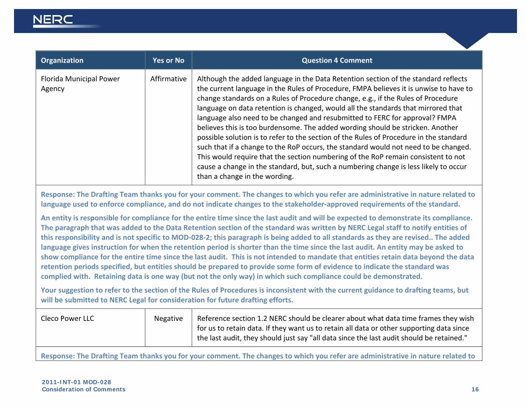
2011-INT-01 MOD-028 Consideration of Comments 16
Organization Yes or No Question 4 Comment
Florida Municipal Power Agency
Affirmative Although the added language in the Data Retention section of the standard reflects the current language in the Rules of Procedure, FMPA believes it is unwise to have to change standards on a Rules of Procedure change, e.g., if the Rules of Procedure language on data retention is changed, would all the standards that mirrored that language also need to be changed and resubmitted to FERC for approval? FMPA believes this is too burdensome. The added wording should be stricken. Another possible solution is to refer to the section of the Rules of Procedure in the standard such that if a change to the RoP occurs, the standard would not need to be changed. This would require that the section numbering of the RoP remain consistent to not cause a change in the standard, but, such a numbering change is less likely to occur than a change in the wording.
Response: The Drafting Team thanks you for your comment. The changes to which you refer are administrative in nature related to language used to enforce compliance, and do not indicate changes to the stakeholder-approved requirements of the standard.
An entity is responsible for compliance for the entire time since the last audit and will be expected to demonstrate its compliance. The paragraph that was added to the Data Retention section of the standard was written by NERC Legal staff to notify entities of this responsibility and is not specific to MOD-028-2; this paragraph is being added to all standards as they are revised.. The added language gives instruction for when the retention period is shorter than the time since the last audit. An entity may be asked to show compliance for the entire time since the last audit. This is not intended to mandate that entities retain data beyond the data retention periods specified, but entities should be prepared to provide some form of evidence to indicate the standard was complied with. Retaining data is one way (but not the only way) in which such compliance could be demonstrated.
Your suggestion to refer to the section of the Rules of Procedures is inconsistent with the current guidance to drafting teams, but will be submitted to NERC Legal for consideration for future drafting efforts.
Cleco Power LLC Negative Reference section 1.2 NERC should be clearer about what data time frames they wish for us to retain data. If they want us to retain all data or other supporting data since the last audit, they should just say "all data since the last audit should be retained."
Response: The Drafting Team thanks you for your comment. The changes to which you refer are administrative in nature related to

2011-INT-01 MOD-028 Consideration of Comments 17
Organization Yes or No Question 4 Comment
language used to enforce compliance, and do not indicate changes to the stakeholder-approved requirements of the standard.
Data should be retained as stated in the original standard. The added language gives instruction for when the retention period is shorter than the time since the last audit. An entity is responsible for compliance for the entire time since the last audit and will be expected to demonstrate its compliance. The paragraph that was added to the Data Retention section of the standard was written by NERC Legal staff to notify entities of this responsibility and is not specific to MOD-028-2; this paragraph is being added to all standards as they are revised.. This is not intended to mandate that entities retain data beyond the data retention periods specified, but entities should be prepared to provide some form of evidence to indicate the standard was complied with. Retaining data is one way (but not the only way) in which such compliance could be demonstrated.
Gainesville Regional Utilities Negative I am OK with the changes in R3 to consolidate the two time frames which are sensible and consistent with the intent of the original standard. But, the changes under section D1.1 are not within the scope of the SAR and were not part of the interpretation request. The changes under Section D1.2 were not part of the SAR or interpretation request and are inconsistent with the original standard drafted by the technical experts, and approved by the industry. I understand that the standards team was aware of the amount of data potentially involved with the different requirements, set specific time lines to allow for verification of compliance with the standard without creating an undue burden in terms of data management, storage and recovery. The Team and the Industry in approving the standard felt that those time frames were appropriate, and that not every piece of data - some of which changes multiple times in an hour - need to be retained for three plus years. Ideally the SAR team would reconsider this change and return to the time frames originally determined by the drafting team and industry. At a minimum however the SAR team should allow 180 days after regulatory approval since multiple applications provided by various third party vendors may need to be modified to accommodate this change. The Team should also clarify that this expanded evidence requirement applies from the effective date of MOD 028-2 and beyond since MOD 028-1 did not require this longer term retention and data may already have been deleted.
Response: The Drafting Team thanks you for your comment. The changes to which you refer are administrative in nature related to

2011-INT-01 MOD-028 Consideration of Comments 18
Organization Yes or No Question 4 Comment
language used to enforce compliance, and do not indicate changes to the stakeholder-approved requirements of the standard.
Data should be retained as stated in the original standard. The added language gives instruction for when the retention period is shorter than the time since the last audit. An entity is responsible for compliance for the entire time since the last audit and will be expected to demonstrate its compliance. The paragraph that was added to the Data Retention section of the standard was written by NERC Legal staff to notify entities of this responsibility and is not specific to MOD-028-2; this paragraph is being added to all standards as they are revised.. This is not intended to mandate that entities retain data beyond the data retention periods specified, but entities should be prepared to provide some form of evidence to indicate the standard was complied with. Retaining data is one way (but not the only way) in which such compliance could be demonstrated.
Georgia Transmission Corporation
Negative The proposed revision goes beyond FP&L’s request for interpretation. The VRF levels have been changed to “PENDING”. The SAR states, “Because FERC has not yet ruled on the VRFs for this standard, they have been marked as PENDING in order to not distract from the discussion of the modification.” Please describe what input was given by the Interpretation Team. Please describe how this change was done in accordance with Reliability Standards Consensus Development Process - Step 5 of the Reliability Standards Development Procedure. In Order 729, “the Commission accepts the ERO’s commitment to reevaluate the violation risk factors and violation severity levels associated with these MOD Reliability Standards through an open stakeholder process to ensure that they are consistent with the intent of violation risk factor definitions and Commission precedent.” Changing the VRF levels in this “Rapid” approach and requesting a parallel vote prior to obtaining industry feedback (1) is not an open stakeholder process, (2) is making changes to one MOD standard while leaving the other MOD standards unchanged, (3) leaves auditors and the industry without any guidance as to the VRFs for MOD-028-2 requirements, and (4) does not appear in accordance with the Reliability Standards Development Procedure. GTC recommends following the Commission’s determination outlined in Order 729 to reevaluate the VRF associated with ALL of the proposed MOD Reliability Standards through a separate, open stakeholder process which could ensure the VRFs and VSLs are consistent with the intent of violation risk factor definitions and Commission precedent.
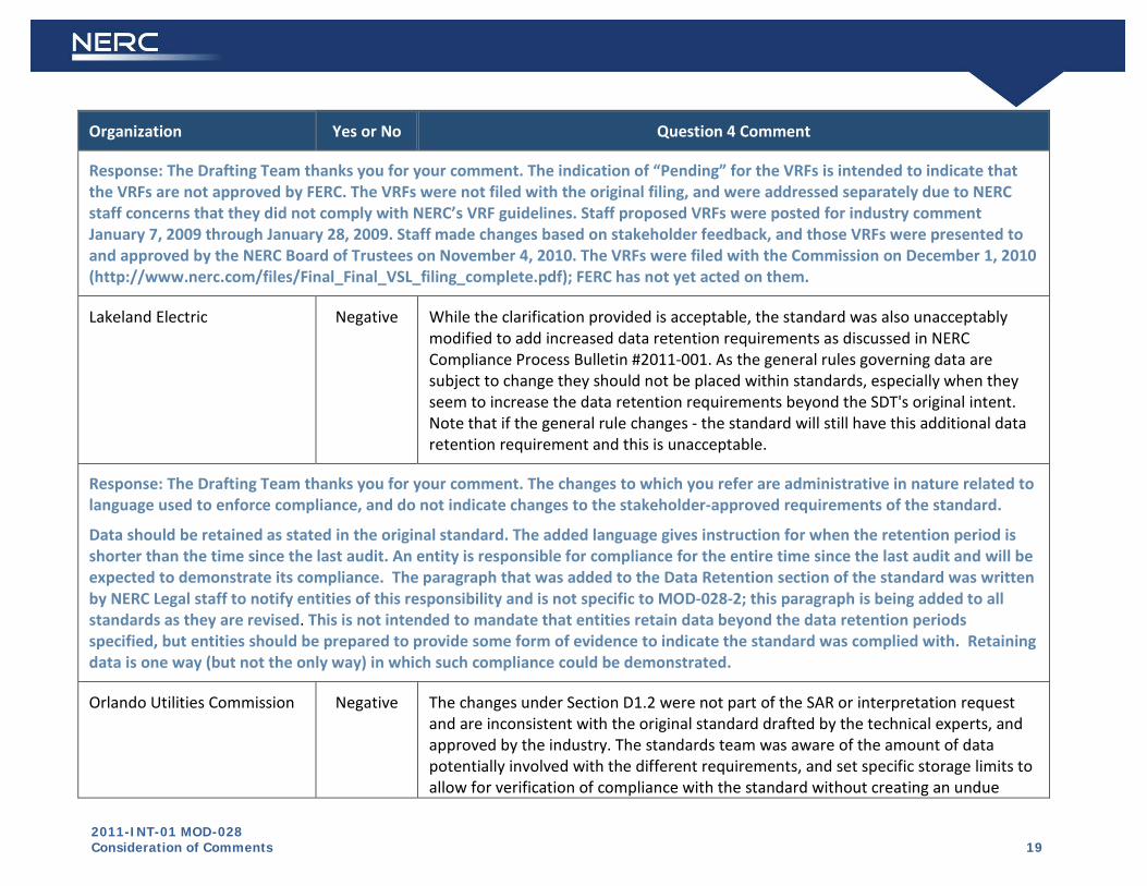
2011-INT-01 MOD-028 Consideration of Comments 19
Organization Yes or No Question 4 Comment
Response: The Drafting Team thanks you for your comment. The indication of “Pending” for the VRFs is intended to indicate that the VRFs are not approved by FERC. The VRFs were not filed with the original filing, and were addressed separately due to NERC staff concerns that they did not comply with NERC’s VRF guidelines. Staff proposed VRFs were posted for industry comment January 7, 2009 through January 28, 2009. Staff made changes based on stakeholder feedback, and those VRFs were presented to and approved by the NERC Board of Trustees on November 4, 2010. The VRFs were filed with the Commission on December 1, 2010 (http://www.nerc.com/files/Final_Final_VSL_filing_complete.pdf); FERC has not yet acted on them.
Lakeland Electric Negative While the clarification provided is acceptable, the standard was also unacceptably modified to add increased data retention requirements as discussed in NERC Compliance Process Bulletin #2011-001. As the general rules governing data are subject to change they should not be placed within standards, especially when they seem to increase the data retention requirements beyond the SDT's original intent. Note that if the general rule changes - the standard will still have this additional data retention requirement and this is unacceptable.
Response: The Drafting Team thanks you for your comment. The changes to which you refer are administrative in nature related to language used to enforce compliance, and do not indicate changes to the stakeholder-approved requirements of the standard.
Data should be retained as stated in the original standard. The added language gives instruction for when the retention period is shorter than the time since the last audit. An entity is responsible for compliance for the entire time since the last audit and will be expected to demonstrate its compliance. The paragraph that was added to the Data Retention section of the standard was written by NERC Legal staff to notify entities of this responsibility and is not specific to MOD-028-2; this paragraph is being added to all standards as they are revised. This is not intended to mandate that entities retain data beyond the data retention periods specified, but entities should be prepared to provide some form of evidence to indicate the standard was complied with. Retaining data is one way (but not the only way) in which such compliance could be demonstrated.
Orlando Utilities Commission Negative The changes under Section D1.2 were not part of the SAR or interpretation request and are inconsistent with the original standard drafted by the technical experts, and approved by the industry. The standards team was aware of the amount of data potentially involved with the different requirements, and set specific storage limits to allow for verification of compliance with the standard without creating an undue

2011-INT-01 MOD-028 Consideration of Comments 20
Organization Yes or No Question 4 Comment
burden in terms of data management, storage and recovery. As written this revised version effectively set’s aside the time limits set by the drafting team and would require every piece of data to be indexed and retained for three years.
Response: The Drafting Team thanks you for your comment. The changes to which you refer are administrative in nature related to language used to enforce compliance, and do not indicate changes to the stakeholder-approved requirements of the standard.
Data should be retained as stated in the original standard. The added language gives instruction for when the retention period is shorter than the time since the last audit. An entity is responsible for compliance for the entire time since the last audit and will be expected to demonstrate its compliance. The paragraph that was added to the Data Retention section of the standard was written by NERC Legal staff to notify entities of this responsibility and is not specific to MOD-028-2; this paragraph is being added to all standards as they are revised. This is not intended to mandate that entities retain data beyond the data retention periods specified, but entities should be prepared to provide some form of evidence to indicate the standard was complied with. Retaining data is one way (but not the only way) in which such compliance could be demonstrated.
Seminole Electric Cooperative, Inc.
Negative The reason for voting against this is the insertion of language in section D.1.2. (Compliance, Data Retention) which is unreasonably broad and imposes new and immediate evidence requirements. Significant modifications to systems will likely be required to meet these requirements.
Response: The Drafting Team thanks you for your comment. The changes to which you refer are administrative in nature related to language used to enforce compliance, and do not indicate changes to the stakeholder-approved requirements of the standard.
Data should be retained as stated in the original standard. The added language gives instruction for when the retention period is shorter than the time since the last audit. An entity is responsible for compliance for the entire time since the last audit and will be expected to demonstrate its compliance. The paragraph that was added to the Data Retention section of the standard was written by NERC Legal staff to notify entities of this responsibility and is not specific to MOD-028-2; this paragraph is being added to all standards as they are revised. This is not intended to mandate entities retain data beyond the data retention periods specified, but entities should be prepared to provide some form of evidence to indicate the standard was complied with. Retaining the data is one way (but not the only way) in which such compliance could be demonstrated.
Cleco Power | Cleco Power Negative Reference section 1.2 NERC should be clearer about what data time frames they wish

2011-INT-01 MOD-028 Consideration of Comments 21
Organization Yes or No Question 4 Comment
LLC | Cleco Corporation for us to retain data. If they want us to retain all data or other supporting data since the last audit, they should just say "all data since the last audit should be retained."
Response: The Drafting Team thanks you for your comment. The changes to which you refer are administrative in nature related to language used to enforce compliance, and do not indicate changes to the stakeholder-approved requirements of the standard.
Data should be retained as stated in the original standard. The added language gives instruction for when the retention period is shorter than the time since the last audit. An entity is responsible for compliance for the entire time since the last audit and will be expected to demonstrate its compliance. The paragraph that was added to the Data Retention section of the standard was written by NERC Legal staff to notify entities of this responsibility and is not specific to MOD-028-2; this paragraph is being added to all standards as they are revised. This is not intended to mandate entities retain data beyond the data retention periods specified, but entities should be prepared to provide some form of evidence to indicate the standard was complied with. Retaining the data is one way (but not the only way) in which such compliance could be demonstrated.
Orlando Utilities Commission Negative Interpretation requests are for clarifying a standard, but cannot by definition change what the standard requires. The changes to the evidence required and the retention period is a change from the original standard and should not be made through an interpretation process, especially when the interpretation did not address evidence or retention period.
Response: The Drafting Team thanks you for your comment. The changes to which you refer are administrative in nature related to language used to enforce compliance, and do not indicate changes to the stakeholder-approved requirements of the standard.
Data should be retained as stated in the original standard. The added language gives instruction for when the retention period is shorter than the time since the last audit. An entity is responsible for compliance for the entire time since the last audit and will be expected to demonstrate its compliance. The paragraph that was added to the Data Retention section of the standard was written by NERC Legal staff to notify entities of this responsibility and is not specific to MOD-028-2; this paragraph is being added to all standards as they are revised. This is not intended to mandate entities retain data beyond the data retention periods specified, but entities should be prepared to provide some form of evidence to indicate the standard was complied with. Retaining the data is one way (but not the only way) in which such compliance could be demonstrated.
ReliabilityFirst ReliabilityFirst agrees with that the redlined changes further clarify the intent of R3.1

2011-INT-01 MOD-028 Consideration of Comments 22
Organization Yes or No Question 4 Comment
but noticed one typo. The term “Daily” in part 3.1.3 should not be capitalized since the term “Daily” is not a definition listed in the NERC Glossary of terms.
Response: The Drafting Team thanks you for your comment. R3.1 has been corrected as noted so that the term “daily” is not capitalized.
Northeast Power Coordinating Council
NCEMC Reps
ACES Power Marketing Standards Collaborators
MRO NSRF NONE
Duke Energy
Georgia Transmission Corporation
Manitoba Hydro
Bonneville Power Administration
BPA has no comments or concerns at this time as BPA does not implement this standard.
END OF REPORT
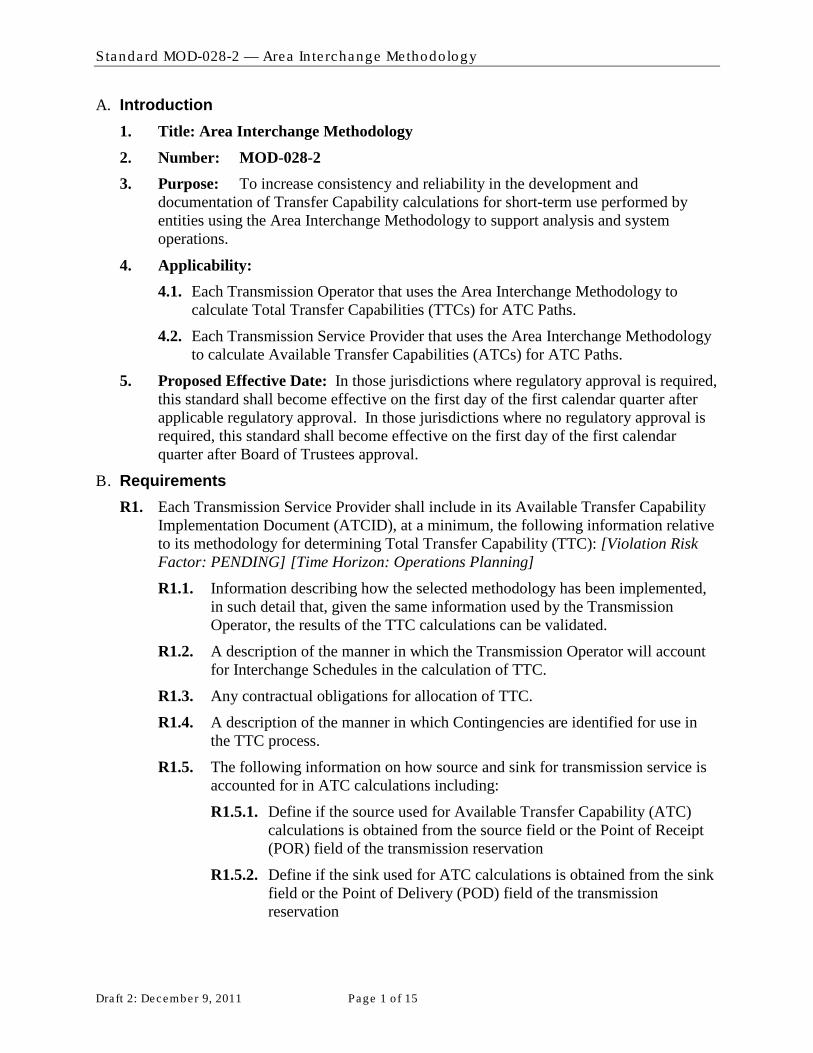
Standard MOD-028-2 — Area In te rchange Methodology
Draft 2: December 9, 2011 Page 1 o f 15
A. Introduction 1. Title: Area Interchange Methodology 2. Number: MOD-028-2 3. Purpose: To increase consistency and reliability in the development and
documentation of Transfer Capability calculations for short-term use performed by entities using the Area Interchange Methodology to support analysis and system operations.
4. Applicability: 4.1. Each Transmission Operator that uses the Area Interchange Methodology to
calculate Total Transfer Capabilities (TTCs) for ATC Paths.
4.2. Each Transmission Service Provider that uses the Area Interchange Methodology to calculate Available Transfer Capabilities (ATCs) for ATC Paths.
5. Proposed Effective Date: In those jurisdictions where regulatory approval is required, this standard shall become effective on the first day of the first calendar quarter after applicable regulatory approval. In those jurisdictions where no regulatory approval is required, this standard shall become effective on the first day of the first calendar quarter after Board of Trustees approval.
B. Requirements R1. Each Transmission Service Provider shall include in its Available Transfer Capability
Implementation Document (ATCID), at a minimum, the following information relative to its methodology for determining Total Transfer Capability (TTC): [Violation Risk Factor: PENDING] [Time Horizon: Operations Planning] R1.1. Information describing how the selected methodology has been implemented,
in such detail that, given the same information used by the Transmission Operator, the results of the TTC calculations can be validated.
R1.2. A description of the manner in which the Transmission Operator will account for Interchange Schedules in the calculation of TTC.
R1.3. Any contractual obligations for allocation of TTC.
R1.4. A description of the manner in which Contingencies are identified for use in the TTC process.
R1.5. The following information on how source and sink for transmission service is accounted for in ATC calculations including:
R1.5.1. Define if the source used for Available Transfer Capability (ATC) calculations is obtained from the source field or the Point of Receipt (POR) field of the transmission reservation
R1.5.2. Define if the sink used for ATC calculations is obtained from the sink field or the Point of Delivery (POD) field of the transmission reservation

Standard MOD-028-2 — Area In te rchange Methodology
Draft 2: December 9, 2011 Page 2 o f 15
R1.5.3. The source/sink or POR/POD identification and mapping to the model.
R1.5.4. If the Transmission Service Provider’s ATC calculation process involves a grouping of generation, the ATCID must identify how these generators participate in the group.
R2. When calculating TTC for ATC Paths, the Transmission Operator shall use a Transmission model that contains all of the following: [Violation Risk Factor: PENDING] [Time Horizon: Operations Planning] R2.1. Modeling data and topology of its Reliability Coordinator’s area of
responsibility. Equivalent representation of radial lines and facilities 161 kV or below is allowed.
R2.2. Modeling data and topology (or equivalent representation) for immediately adjacent and beyond Reliability Coordination areas.
R2.3. Facility Ratings specified by the Generator Owners and Transmission Owners.
R3. When calculating TTCs for ATC Paths, the Transmission Operator shall include the following data for the Transmission Service Provider’s area. The Transmission Operator shall also include the following data associated with Facilities that are explicitly represented in the Transmission model, as provided by adjacent Transmission Service Providers and any other Transmission Service Providers with which coordination agreements have been executed: [Violation Risk Factor: PENDING] [Time Horizon: Operations Planning]
R3.1. For TTCs, use the following (as well as any other values and additional parameters as specified in the ATCID):
R3.1.1. Expected generation and Transmission outages, additions, and retirements, included as specified in the ATCID.
R3.1.2. A daily or hourly load forecast for TTCs used in current-day and next-day ATC calculations.
R3.1.3. A daily load forecast for TTCs used in ATC calculations for days two through 31.
R3.1.4. A monthly load forecast for TTCs used in ATC calculations for months two through 13 months TTCs.
R3.1.5. Unit commitment and dispatch order, to include all designated network resources and other resources that are committed or have the legal obligation to run, (within or out of economic dispatch) as they are expected to run.
R4. When calculating TTCs for ATC Paths, the Transmission Operator shall meet all of the following conditions: [Violation Risk Factor: PENDING] [Time Horizon: Operations Planning] R4.1. Use all Contingencies meeting the criteria described in the ATCID.
R4.2. Respect any contractual allocations of TTC.

Standard MOD-028-2 — Area In te rchange Methodology
Draft 2: December 9, 2011 Page 3 o f 15
R4.3. Include, for each time period, the Firm Transmission Service expected to be scheduled as specified in the ATCID (filtered to reduce or eliminate duplicate impacts from transactions using Transmission service from multiple Transmission Service Providers) for the Transmission Service Provider, all adjacent Transmission Service Providers, and any Transmission Service Providers with which coordination agreements have been executed modeling the source and sink as follows:
- If the source, as specified in the ATCID, has been identified in the reservation and it is discretely modeled in the Transmission Service Provider’s Transmission model, use the discretely modeled point as the source.
- If the source, as specified in the ATCID, has been identified in the reservation and the point can be mapped to an “equivalence” or “aggregate representation” in the Transmission Service Provider’s Transmission model, use the modeled equivalence or aggregate as the source.
- If the source, as specified in the ATCID, has been identified in the reservation and the point cannot be mapped to a discretely modeled point, an “equivalence,” or an “aggregate representation” in the Transmission Service Provider’s Transmission model, use the immediately adjacent Balancing Authority associated with the Transmission Service Provider from which the power is to be received as the source.
- If the source, as specified in the ATCID, has not been identified in the reservation, use the immediately adjacent Balancing Authority associated with the Transmission Service Provider from which the power is to be received as the source.
- If the sink, as specified in the ATCID, has been identified in the reservation and it is discretely modeled in the Transmission Service Provider’s Transmission model, use the discretely modeled point shall as the sink.
- If the sink, as specified in the ATCID, has been identified in the reservation and the point can be mapped to an “equivalence” or “aggregate representation” in the Transmission Service Provider’s Transmission model, use the modeled equivalence or aggregate as the sink.
- If the sink, as specified in the ATCID, has been identified in the reservation and the point can not be mapped to a discretely modeled point, an “equivalence,” or an “aggregate representation” in the Transmission Service Provider’s Transmission model, use the immediately adjacent Balancing Authority associated with the Transmission Service Provider to which the power is to be delivered as the sink.
- If the sink, as specified in the ATCID, has not been identified in the reservation, use the immediately adjacent Balancing Authority associated with the Transmission Service Provider to which the power is being delivered as the sink.
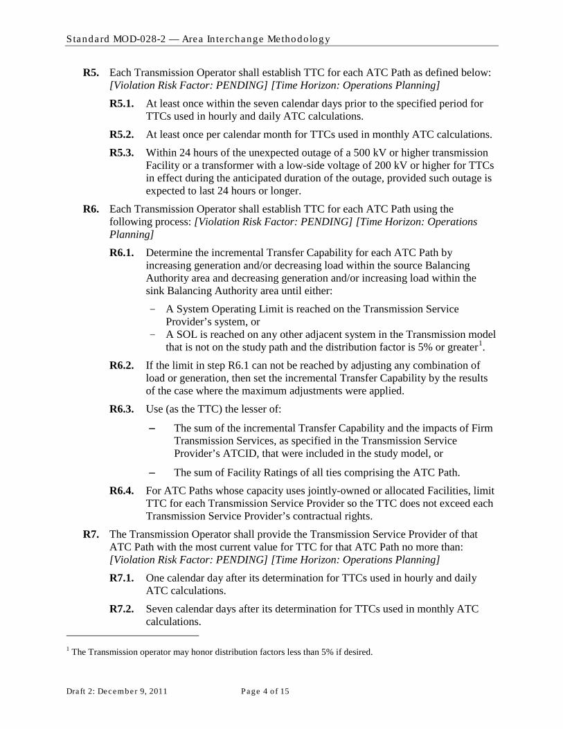
Standard MOD-028-2 — Area In te rchange Methodology
Draft 2: December 9, 2011 Page 4 o f 15
R5. Each Transmission Operator shall establish TTC for each ATC Path as defined below: [Violation Risk Factor: PENDING] [Time Horizon: Operations Planning] R5.1. At least once within the seven calendar days prior to the specified period for
TTCs used in hourly and daily ATC calculations.
R5.2. At least once per calendar month for TTCs used in monthly ATC calculations.
R5.3. Within 24 hours of the unexpected outage of a 500 kV or higher transmission Facility or a transformer with a low-side voltage of 200 kV or higher for TTCs in effect during the anticipated duration of the outage, provided such outage is expected to last 24 hours or longer.
R6. Each Transmission Operator shall establish TTC for each ATC Path using the following process: [Violation Risk Factor: PENDING] [Time Horizon: Operations Planning] R6.1. Determine the incremental Transfer Capability for each ATC Path by
increasing generation and/or decreasing load within the source Balancing Authority area and decreasing generation and/or increasing load within the sink Balancing Authority area until either:
- A System Operating Limit is reached on the Transmission Service Provider’s system, or
- A SOL is reached on any other adjacent system in the Transmission model that is not on the study path and the distribution factor is 5% or greater1
R6.2. If the limit in step R6.1 can not be reached by adjusting any combination of load or generation, then set the incremental Transfer Capability by the results of the case where the maximum adjustments were applied.
.
R6.3. Use (as the TTC) the lesser of:
− The sum of the incremental Transfer Capability and the impacts of Firm Transmission Services, as specified in the Transmission Service Provider’s ATCID, that were included in the study model, or
− The sum of Facility Ratings of all ties comprising the ATC Path.
R6.4. For ATC Paths whose capacity uses jointly-owned or allocated Facilities, limit TTC for each Transmission Service Provider so the TTC does not exceed each Transmission Service Provider’s contractual rights.
R7. The Transmission Operator shall provide the Transmission Service Provider of that ATC Path with the most current value for TTC for that ATC Path no more than: [Violation Risk Factor: PENDING] [Time Horizon: Operations Planning]
R7.1. One calendar day after its determination for TTCs used in hourly and daily ATC calculations.
R7.2. Seven calendar days after its determination for TTCs used in monthly ATC calculations.
1 The Transmission operator may honor distribution factors less than 5% if desired.
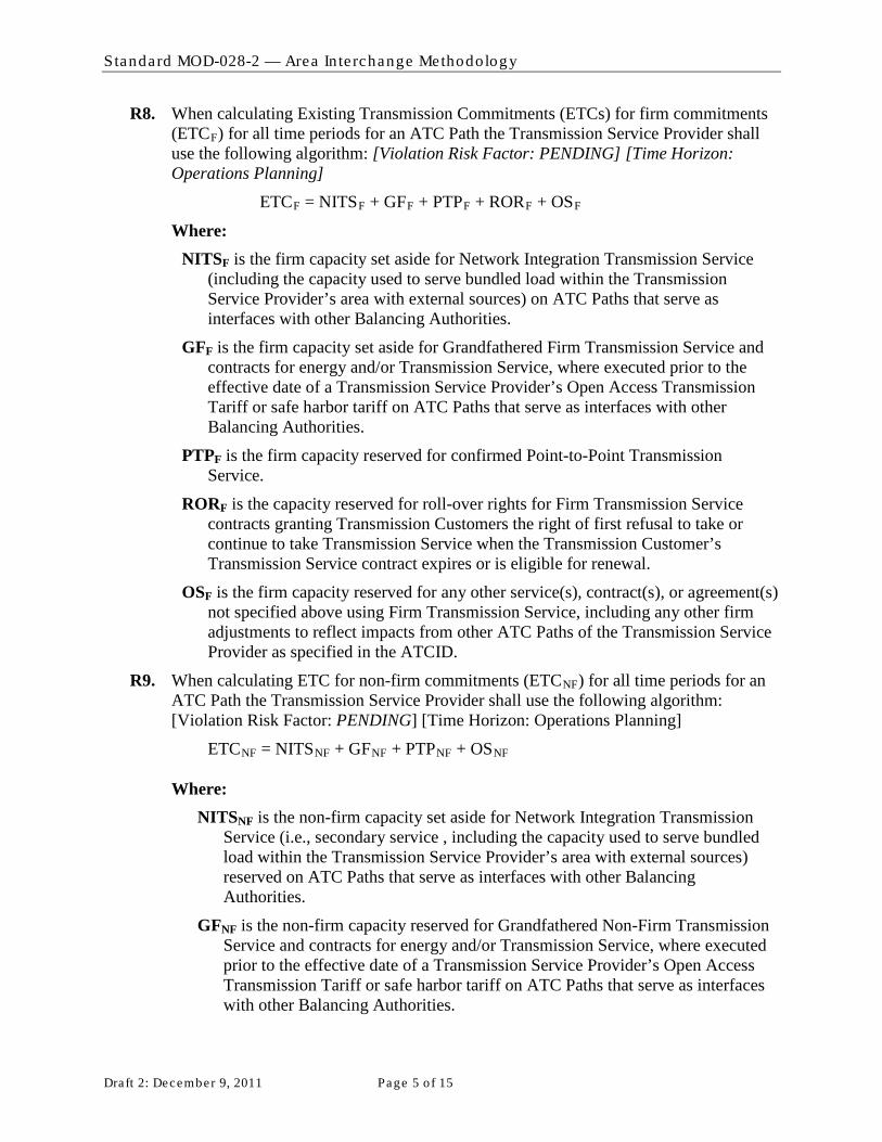
Standard MOD-028-2 — Area In te rchange Methodology
Draft 2: December 9, 2011 Page 5 o f 15
R8. When calculating Existing Transmission Commitments (ETCs) for firm commitments (ETCF
ETC
) for all time periods for an ATC Path the Transmission Service Provider shall use the following algorithm: [Violation Risk Factor: PENDING] [Time Horizon: Operations Planning]
F = NITSF + GFF + PTPF + RORF + OS
Where: F
NITSF is the firm capacity set aside for Network Integration Transmission Service (including the capacity used to serve bundled load within the Transmission Service Provider’s area with external sources) on ATC Paths that serve as interfaces with other Balancing Authorities.
GFF is the firm capacity set aside for Grandfathered Firm Transmission Service and contracts for energy and/or Transmission Service, where executed prior to the effective date of a Transmission Service Provider’s Open Access Transmission Tariff or safe harbor tariff on ATC Paths that serve as interfaces with other Balancing Authorities.
PTPF is the firm capacity reserved for confirmed Point-to-Point Transmission Service.
RORF is the capacity reserved for roll-over rights for Firm Transmission Service contracts granting Transmission Customers the right of first refusal to take or continue to take Transmission Service when the Transmission Customer’s Transmission Service contract expires or is eligible for renewal.
OSF is the firm capacity reserved for any other service(s), contract(s), or agreement(s) not specified above using Firm Transmission Service, including any other firm adjustments to reflect impacts from other ATC Paths of the Transmission Service Provider as specified in the ATCID.
R9. When calculating ETC for non-firm commitments (ETCNF
ETC
) for all time periods for an ATC Path the Transmission Service Provider shall use the following algorithm: [Violation Risk Factor: PENDING] [Time Horizon: Operations Planning]
NF = NITSNF + GFNF + PTPNF + OS
NF
Where: NITSNF is the non-firm capacity set aside for Network Integration Transmission
Service (i.e., secondary service , including the capacity used to serve bundled load within the Transmission Service Provider’s area with external sources) reserved on ATC Paths that serve as interfaces with other Balancing Authorities.
GFNF is the non-firm capacity reserved for Grandfathered Non-Firm Transmission Service and contracts for energy and/or Transmission Service, where executed prior to the effective date of a Transmission Service Provider’s Open Access Transmission Tariff or safe harbor tariff on ATC Paths that serve as interfaces with other Balancing Authorities.

Standard MOD-028-2 — Area In te rchange Methodology
Draft 2: December 9, 2011 Page 6 o f 15
PTPNF is non-firm capacity reserved for confirmed Point-to-Point Transmission Service.
OSNF is the non-firm capacity reserved for any other service(s), contract(s), or agreement(s) not specified above using Non-Firm Transmission Service, including any other firm adjustments to reflect impacts from other ATC Paths of the Transmission Service Provider as specified in the ATCID.
R10. When calculating firm ATC for an ATC Path for a specified period, the Transmission Service Provider shall utilize the following algorithm: [Violation Risk Factor: PENDING] [Time Horizon: Operations Planning]
ATCF = TTC – ETCF – CBM – TRM + PostbacksF + counterflowsF
Where: ATCF is the firm Available Transfer Capability for the ATC Path for that period.
TTC is the Total Transfer Capability of the ATC Path for that period.
ETCF is the sum of existing firm Transmission commitments for the ATC Path during that period.
CBM is the Capacity Benefit Margin for the ATC Path during that period.
TRM is the Transmission Reliability Margin for the ATC Path during that period.
PostbacksF are changes to firm ATC due to a change in the use of Transmission Service for that period, as defined in Business Practices.
counterflowsF are adjustments to firm ATC as determined by the Transmission Service Provider and specified in the ATCID.
R11. When calculating non-firm ATC for a ATC Path for a specified period, the Transmission Service Provider shall use the following algorithm: [Violation Risk Factor: Lower] [Time Horizon: Operations Planning] ATCNF = TTC – ETCF - ETCNF – CBMS – TRMU + PostbacksNF + counterflowsNF
Where: ATCNF is the non-firm Available Transfer Capability for the ATC Path for that
period.
TTC is the Total Transfer Capability of the ATC Path for that period.
ETCF is the sum of existing firm Transmission commitments for the ATC Path during that period.
ETCNF is the sum of existing non-firm Transmission commitments for the ATC Path during that period.
CBMS is the Capacity Benefit Margin for the ATC Path that has been scheduled without a separate reservation during that period.
TRMU is the Transmission Reliability Margin for the ATC Path that has not been released for sale (unreleased) as non-firm capacity by the Transmission Service Provider during that period.

Standard MOD-028-2 — Area In te rchange Methodology
Draft 2: December 9, 2011 Page 7 o f 15
PostbacksNF are changes to non-firm ATC due to a change in the use of Transmission Service for that period, as defined in Business Practices.
counterflowsNF are adjustments to non-firm ATC as determined by the Transmission Service Provider and specified in the ATCID.
C. Measures M1. Each Transmission Service Provider shall provide its current ATCID that has the
information described in R1 to show compliance with R1. (R1)
M2. Each Transmission Operator shall provide evidence including the model used to calculate TTC as well as other evidence (such as Facility Ratings provided by facility owners, written documentation, logs, and data) to show that the modeling requirements in R2 were met. (R2)
M3. Each Transmission Operator shall provide evidence, including scheduled outages, facility additions and retirements, (such as written documentation, logs, and data) that the data described in R3 and R4 were included in the determination of TTC as specified in the ATCID. (R3)
M4. Each Transmission Operator shall provide the contingencies used in determining TTC and the ATCID as evidence to show that the contingencies described in the ATCID were included in the determination of TTC. (R4)
M5. Each Transmission Operator shall provide copies of contracts that contain requirements to allocate TTCs and TTC values to show that any contractual allocations of TTC were respected as required in R4.2. (R4)
M6. Each Transmission Operator shall provide evidence (such as copies of coordination agreements, reservations, interchange transactions, or other documentation) to show that firm reservations were used to estimate scheduled interchange, the modeling of scheduled interchange was based on the rules described in R4.3, and that estimated scheduled interchange was included in the determination of TTC. (R4)
M7. Each Transmission Operator shall provide evidence (such as logs and data and dated copies of requests from the Transmission Service Provider to establish TTCs at specific intervals) that TTCs have been established at least once in the calendar week prior to the specified period for TTCs used in hourly and daily ATC calculations, at least once per calendar month for TTCs used in monthly ATC calculations, and within 24 hours of the unexpected outage of a 500 kV or higher transmission Facility or a autotransformer with a low-side voltage of 200 kV or higher for TTCs in effect during the anticipated duration of the outage; provided such outage is expected to last 24 hours or longer in duration per the specifications in R5.(R5)
M8. Each Transmission Operator shall provide evidence (such as written documentation) that TTCs have been calculated using the process described in R6. (R6)
M9. Each Transmission Operator shall have evidence including a copy of the latest calculated TTC values along with a dated copy of email notices or other equivalent evidence to show that it provided its Transmission Service Provider with the most current values for TTC in accordance with R7. (R7)

Standard MOD-028-2 — Area In te rchange Methodology
Draft 2: December 9, 2011 Page 8 o f 15
M10. The Transmission Service Provider shall demonstrate compliance with R8 by recalculating firm ETC
M11. The Transmission Service Provider shall demonstrate compliance with R9 by recalculating non-firm ETC for any specific time period as described in (MOD-001 R2), using the algorithm defined in R9 and with data used to calculate the specified value for the designated time period. The data used must meet the requirements specified in MOD-028-1 and the ATCID. To account for differences that may occur when recalculating the value (due to mixing automated and manual processes), any recalculated value that is within +/- 15% or 15 MW, whichever is greater, of the originally calculated value, is evidence that the Transmission Service Provider used the algorithm in R8 to calculate its non-firm ETC. (R9)
for any specific time period as described in (MOD-001 R2), using the algorithm defined in R8 and with data used to calculate the specified value for the designated time period. The data used must meet the requirements specified in MOD-028-1 and the ATCID. To account for differences that may occur when recalculating the value (due to mixing automated and manual processes), any recalculated value that is within +/- 15% or 15 MW, whichever is greater, of the originally calculated value, is evidence that the Transmission Service Provider used the algorithm in R8 to calculate its firm ETC. (R8)
M12. Each Transmission Service Provider shall produce the supporting documentation for the processes used to implement the algorithm that calculates firm ATCs, as required in R10. Such documentation must show that only the variables allowed in R10 were used to calculate firm ATCs, and that the processes use the current values for the variables as determined in the requirements or definitions. Note that any variable may legitimately be zero if the value is not applicable or calculated to be zero (such as counterflows, TRM, CBM, etc…). The supporting documentation may be provided in the same form and format as stored by the Transmission Service Provider. (R10)
M13. Each Transmission Service Provider shall produce the supporting documentation for the processes used to implement the algorithm that calculates non-firm ATCs, as required in R11. Such documentation must show that only the variables allowed in R11 were used to calculate non-firm ATCs, and that the processes use the current values for the variables as determined in the requirements or definitions. Note that any variable may legitimately be zero if the value is not applicable or calculated to be zero (such as counterflows, TRM, CBM, etc…). The supporting documentation may be provided in the same form and format as stored by the Transmission Service Provider. (R11)
D. Compliance 1. Compliance Monitoring Process
1.1. Compliance Enforcement Authority For entities that do not work for the Regional Entity, the Regional Entity shall serve as the Compliance Enforcement Authority.
For functional entities that work for their Regional Entity, the ERO or a Regional Entity approved by the ERO and FERC or other applicable governmental authorities shall serve as the Compliance Enforcement Authority.

Standard MOD-028-2 — Area In te rchange Methodology
Draft 2: December 9, 2011 Page 9 o f 15
1.2. Data Retention
The following evidence retention periods identify the period of time an entity is required to retain specific evidence to demonstrate compliance. For instances where the evidence retention period specified below is shorter than the time since the last audit, the Compliance Enforcement Authority may ask an entity to provide other evidence to show that it was compliant for the full time period since the last audit.
The Transmission Operator and Transmission Service Provider shall keep data or evidence to show compliance as identified below unless directed by its Compliance Enforcement Authority to retain specific evidence for a longer period of time as part of an investigation:
- The Transmission Service Provider shall retain its current, in force ATCID and any prior versions of the ATCID that were in force since the last compliance audit to show compliance with R1.
- The Transmission Operator shall have its latest model used to calculate TTC and evidence of the previous version to show compliance with R2.
- The Transmission Operator shall retain evidence to show compliance with R3 for the most recent 12 months or until the model used to calculate TTC is updated, whichever is longer.
- The Transmission Operator shall retain evidence to show compliance with R4, R5, R6 and R7 for the most recent 12 months.
- The Transmission Service Provider shall retain evidence to show compliance in calculating hourly values required in R8 and R9 for the most recent 14 days; evidence to show compliance in calculating daily values required in R8 and R9 for the most recent 30 days; and evidence to show compliance in calculating monthly values required in R8 and R9 for the most recent 60 days.
- The Transmission Service Provider shall retain evidence to show compliance with R10 and R11 for the most recent 12 months.
- If a Transmission Service Provider or Transmission Operator is found non-compliant, it shall keep information related to the non-compliance until found compliant.
- The Compliance Enforcement Authority shall keep the last audit records and all requested and submitted subsequent audit records.
1.3. Compliance Monitoring and Enforcement Processes: The following processes may be used:
- Compliance Audits
- Self-Certifications
- Spot Checking
- Compliance Violation Investigations
- Self-Reporting
- Complaints

Standard MOD-028-2 — Area In te rchange Methodology
Draft 2: December 9, 2011 Page 10 of 15
1.4. Additional Compliance Information None.

Standard MOD-028-2 — Area In te rchange Methodology
Draft 2: December 9, 2011 Page 11 of 15
2. Violation Severity Levels
R # Lower VSL Moderate VSL High VSL Severe VSL
R1. The Transmission Service Provider has an ATCID but it is missing one of the following:
R1.1
R1.2
R1.3
R1.4
R1.5 (any one or more of its sub-subrequirements)
The Transmission Service Provider has an ATCID but it is missing two of the following:
R1.1
R1.2
R1.3
R1.4
R1.5 (any one or more of its sub-subrequirements)
The Transmission Service Provider has an ATCID but it is missing three of the following:
R1.1
R1.2
R1.3
R1.4
R1.5 (any one or more of its sub-subrequirements)
The Transmission Service Provider has an ATCID but it is missing more than three of the following:
R1.1
R1.2
R1.3
R1.4
R1.5 (any one or more of its sub-subrequirements)
R2. The Transmission Operator used one to ten Facility Ratings that were different from those specified by a Transmission or Generator Owner in their Transmission model.
The Transmission Operator used eleven to twenty Facility Ratings that were different from those specified by a Transmission or Generator Owner in their Transmission model.
One or both of the following:
• The Transmission Operator used twenty-one to thirty Facility Ratings that were different from those specified by a Transmission or Generator Owner in their Transmission model.
• The Transmission Operator did not use a Transmission model that includes modeling data and topology (or equivalent representation) for one adjacent Reliability Coordinator Area.
One or more of the following:
• The Transmission Operator used more than thirty Facility Ratings that were different from those specified by a Transmission or Generator Owner in their Transmission model.
• The Transmission Operator’s model includes equivalent representation of non-radial facilities greater than 161 kV for its own Reliability Coordinator Area.
• The Transmission Operator did not use a Transmission model that includes modeling data and topology (or equivalent representation) for two or more adjacent Reliability Coordinator

Standard MOD-028-2 — Area In te rchange Methodology
Draft 2: December 9, 2011 Page 12 of 15
R # Lower VSL Moderate VSL High VSL Severe VSL
Areas.
R3. The Transmission Operator did not include in the TTC process one to ten expected generation and Transmission outages, additions or retirements as specified in the ATCID.
The Transmission Operator did not include in the TTC process eleven to twenty-five expected generation and Transmission outages, additions or retirements as specified in the ATCID.
The Transmission Operator did not include in the TTC process twenty-six to fifty expected generation and Transmission outages, additions or retirements as specified in the ATCID.
One or more of the following:
• The Transmission Operator did not include in the TTC process more than fifty expected generation and Transmission outages, additions or retirements as specified in the ATCID.
• The Transmission Operator did not include the Load forecast or unit commitment in its TTC calculation as described in R3.
R4.
The Transmission Operator did not model reservations’ sources or sinks as described in R4.3 for more than zero reservations, but not more than 5% of all reservations; or 1 reservation, whichever is greater.
The Transmission Operator did not model reservations’ sources or sinks as described in R4.3 for more than 5%, but not more than 10% of all reservations; or 2 reservations, whichever is greater.
The Transmission Operator did not model reservations’ sources or sinks as described in R4.3 for more than 10%, but not more than 15% of all reservations; or 3 reservations, whichever is greater.
One or more of the following:
• The Transmission Operator did not include in the TTC calculation the contingencies that met the criteria described in the ATCID.
• The Transmission Operator did not respect contractual allocations of TTC.
• The Transmission Operator did not model reservations’ sources or sinks as described in R4.3 for more than 15% of all reservations; or more than 3 reservations, whichever is greater.
• The Transmission Operator did not use firm reservations to estimate interchange or did not

Standard MOD-028-2 — Area In te rchange Methodology
Draft 2: December 9, 2011 Page 13 of 15
R # Lower VSL Moderate VSL High VSL Severe VSL
utilize that estimate in the TTC calculation as described in R4.3.
R5. One or more of the following:
• The Transmission Operator did not establish TTCs for use in hourly or daily ATCs within 7 calendar days but did establish the values within 10 calendar days
• The Transmission Operator did not establish TTCs for use in monthly ATCs during a calendar month but did establish the values within the next consecutive calendar month
One or more of the following:
• The Transmission Operator did not establish TTCs for use in hourly or daily ATCs in 10 calendar days but did establish the values within 13 calendar days
• The Transmission Operator did not establish TTCs for use in monthly ATCs during a two consecutive calendar month period but did establish the values within the third consecutive calendar month
One or more of the following:
• The Transmission Operator did not establish TTCs for used in hourly or daily ATCs in 13 calendar days but did establish the values within 16 calendar days
• The Transmission Operator did not establish TTCs for use in monthly ATCs during a three consecutive calendar month period but did establish the values within the fourth consecutive calendar month
One or more of the following:
• The Transmission Operator did not establish TTCs for used in hourly or daily ATCs in 16 calendar days
• The Transmission Operator did not establish TTCs for use in monthly ATCs during a four or more consecutive calendar month period
• The Transmission Operator did not establish TTCs within 24 hrs of the triggers defined in R5.3
R6. N/A N/A N/A
The Transmission Operator did not calculate TTCs per the process specified in R6.
R7. One or more of the following:
• The Transmission Operator provided its Transmission Service Provider with its ATC Path TTCs used in hourly or daily ATC calculations more than one calendar day after their determination, but not been more than two calendar days after their determination.
• The Transmission Operator
One or more of the following:
• The Transmission Operator provided its Transmission Service Provider with its ATC Path TTCs used in hourly or daily ATC calculations more than two calendar days after their determination, but not been more than three calendar days after their determination.
• The Transmission Operator
One or more of the following:
• The Transmission Operator provided its Transmission Service Provider with its ATC Path TTCs used in hourly or daily ATC calculations more than three calendar days after their determination, but not been more than four calendar days after their determination.
• The Transmission Operator
One or more of the following:
• The Transmission Operator provided its Transmission Service Provider with its ATC Path TTCs used in hourly or daily ATC calculations more than four calendar days after their determination.
• The Transmission Operator did not provide its Transmission Service Provider with its ATC Path TTCs used in hourly or
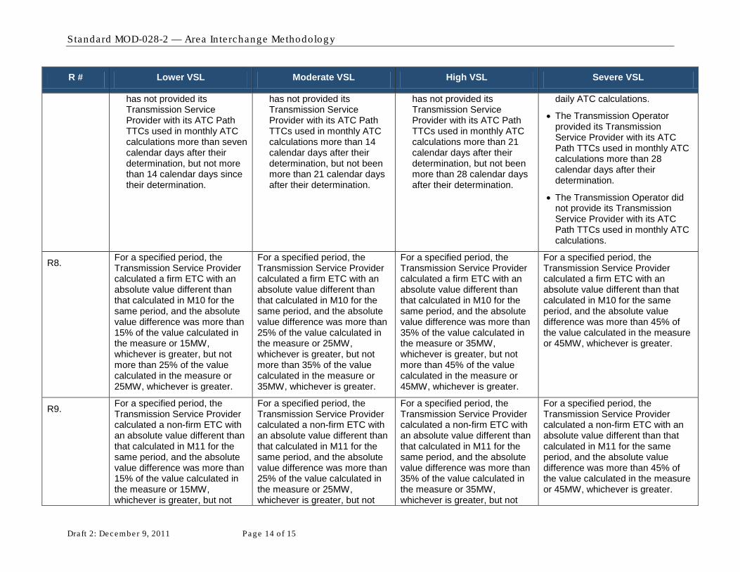
Standard MOD-028-2 — Area In te rchange Methodology
Draft 2: December 9, 2011 Page 14 of 15
R # Lower VSL Moderate VSL High VSL Severe VSL
has not provided its Transmission Service Provider with its ATC Path TTCs used in monthly ATC calculations more than seven calendar days after their determination, but not more than 14 calendar days since their determination.
has not provided its Transmission Service Provider with its ATC Path TTCs used in monthly ATC calculations more than 14 calendar days after their determination, but not been more than 21 calendar days after their determination.
has not provided its Transmission Service Provider with its ATC Path TTCs used in monthly ATC calculations more than 21 calendar days after their determination, but not been more than 28 calendar days after their determination.
daily ATC calculations.
• The Transmission Operator provided its Transmission Service Provider with its ATC Path TTCs used in monthly ATC calculations more than 28 calendar days after their determination.
• The Transmission Operator did not provide its Transmission Service Provider with its ATC Path TTCs used in monthly ATC calculations.
R8. For a specified period, the Transmission Service Provider calculated a firm ETC with an absolute value different than that calculated in M10 for the same period, and the absolute value difference was more than 15% of the value calculated in the measure or 15MW, whichever is greater, but not more than 25% of the value calculated in the measure or 25MW, whichever is greater.
For a specified period, the Transmission Service Provider calculated a firm ETC with an absolute value different than that calculated in M10 for the same period, and the absolute value difference was more than 25% of the value calculated in the measure or 25MW, whichever is greater, but not more than 35% of the value calculated in the measure or 35MW, whichever is greater.
For a specified period, the Transmission Service Provider calculated a firm ETC with an absolute value different than that calculated in M10 for the same period, and the absolute value difference was more than 35% of the value calculated in the measure or 35MW, whichever is greater, but not more than 45% of the value calculated in the measure or 45MW, whichever is greater.
For a specified period, the Transmission Service Provider calculated a firm ETC with an absolute value different than that calculated in M10 for the same period, and the absolute value difference was more than 45% of the value calculated in the measure or 45MW, whichever is greater.
R9. For a specified period, the Transmission Service Provider calculated a non-firm ETC with an absolute value different than that calculated in M11 for the same period, and the absolute value difference was more than 15% of the value calculated in the measure or 15MW, whichever is greater, but not
For a specified period, the Transmission Service Provider calculated a non-firm ETC with an absolute value different than that calculated in M11 for the same period, and the absolute value difference was more than 25% of the value calculated in the measure or 25MW, whichever is greater, but not
For a specified period, the Transmission Service Provider calculated a non-firm ETC with an absolute value different than that calculated in M11 for the same period, and the absolute value difference was more than 35% of the value calculated in the measure or 35MW, whichever is greater, but not
For a specified period, the Transmission Service Provider calculated a non-firm ETC with an absolute value different than that calculated in M11 for the same period, and the absolute value difference was more than 45% of the value calculated in the measure or 45MW, whichever is greater.

Standard MOD-028-2 — Area In te rchange Methodology
Draft 2: December 9, 2011 Page 15 of 15
R # Lower VSL Moderate VSL High VSL Severe VSL
more than 25% of the value calculated in the measure or 25MW, whichever is greater.
more than 35% of the value calculated in the measure or 35MW, whichever is greater...
more than 45% of the value calculated in the measure or 45MW, whichever is greater.
R10. The Transmission Service Provider did not use all the elements defined in R10 when determining firm ATC, or used additional elements, for more than zero ATC Paths, but not more than 5% of all ATC Paths or 1 ATC Path (whichever is greater).
The Transmission Service Provider did not use all the elements defined in R10 when determining firm ATC, or used additional elements, for more than 5% of all ATC Paths or 1 ATC Path (whichever is greater), but not more than 10% of all ATC Paths or 2 ATC Paths (whichever is greater).
The Transmission Service Provider did not use all the elements defined in R10 when determining firm ATC, or used additional elements, for more than 10% of all ATC Paths or 2 ATC Paths (whichever is greater), but not more than 15% of all ATC Paths or 3 ATC Paths (whichever is greater).
The Transmission Service Provider did not use all the elements defined in R10 when determining firm ATC, or used additional elements, for more than 15% of all ATC Paths or more than 3 ATC Paths (whichever is greater).
R11. The Transmission Service Provider did not use all the elements defined in R11 when determining non-firm ATC, or used additional elements, for more than zero ATC Paths, but not more than 5% of all ATC Paths or 1 ATC Path (whichever is greater).
The Transmission Service Provider did not use all the elements defined in R11 when determining non-firm ATC, or used additional elements, for more than 5% of all ATC Paths or 1 ATC Path (whichever is greater), but not more than 10% of all ATC Paths or 2 ATC Paths (whichever is greater).
The Transmission Service Provider did not use all the elements defined in R11 when determining non-firm ATC, or used additional elements, for more than 10% of all ATC Paths or 2 ATC Paths (whichever is greater), but not more than 15% of all ATC Paths or 3 ATC Paths (whichever is greater).
The Transmission Service Provider did not use all the elements defined in R11 when determining non-firm ATC, or used additional elements, for more than 15% of all ATC Paths or more than 3 ATC Paths (whichever is greater).
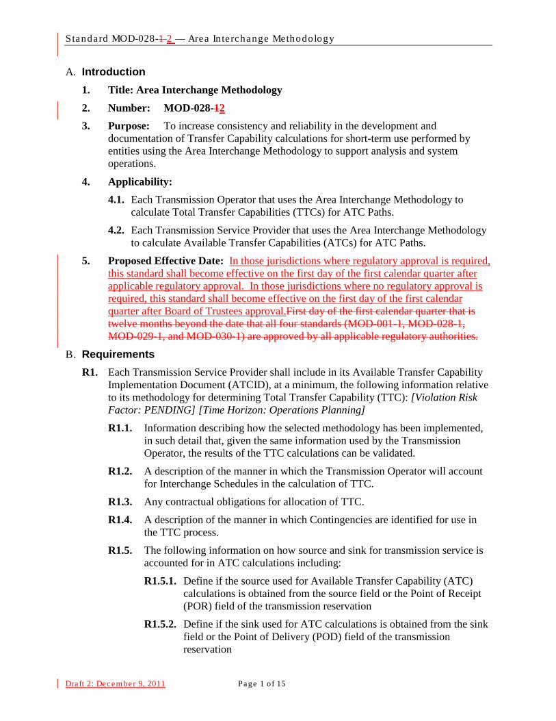
Standard MOD-028-1 2 — Area In te rchange Methodology
Draft 2: December 9, 2011 Page 1 o f 15
A. Introduction 1. Title: Area Interchange Methodology 2. Number: MOD-028-12 3. Purpose: To increase consistency and reliability in the development and
documentation of Transfer Capability calculations for short-term use performed by entities using the Area Interchange Methodology to support analysis and system operations.
4. Applicability: 4.1. Each Transmission Operator that uses the Area Interchange Methodology to
calculate Total Transfer Capabilities (TTCs) for ATC Paths.
4.2. Each Transmission Service Provider that uses the Area Interchange Methodology to calculate Available Transfer Capabilities (ATCs) for ATC Paths.
5. Proposed Effective Date: In those jurisdictions where regulatory approval is required, this standard shall become effective on the first day of the first calendar quarter after applicable regulatory approval. In those jurisdictions where no regulatory approval is required, this standard shall become effective on the first day of the first calendar quarter after Board of Trustees approval.First day of the first calendar quarter that is twelve months beyond the date that all four standards (MOD-001-1, MOD-028-1, MOD-029-1, and MOD-030-1) are approved by all applicable regulatory authorities.
B. Requirements R1. Each Transmission Service Provider shall include in its Available Transfer Capability
Implementation Document (ATCID), at a minimum, the following information relative to its methodology for determining Total Transfer Capability (TTC): [Violation Risk Factor: PENDING] [Time Horizon: Operations Planning] R1.1. Information describing how the selected methodology has been implemented,
in such detail that, given the same information used by the Transmission Operator, the results of the TTC calculations can be validated.
R1.2. A description of the manner in which the Transmission Operator will account for Interchange Schedules in the calculation of TTC.
R1.3. Any contractual obligations for allocation of TTC.
R1.4. A description of the manner in which Contingencies are identified for use in the TTC process.
R1.5. The following information on how source and sink for transmission service is accounted for in ATC calculations including:
R1.5.1. Define if the source used for Available Transfer Capability (ATC) calculations is obtained from the source field or the Point of Receipt (POR) field of the transmission reservation
R1.5.2. Define if the sink used for ATC calculations is obtained from the sink field or the Point of Delivery (POD) field of the transmission reservation
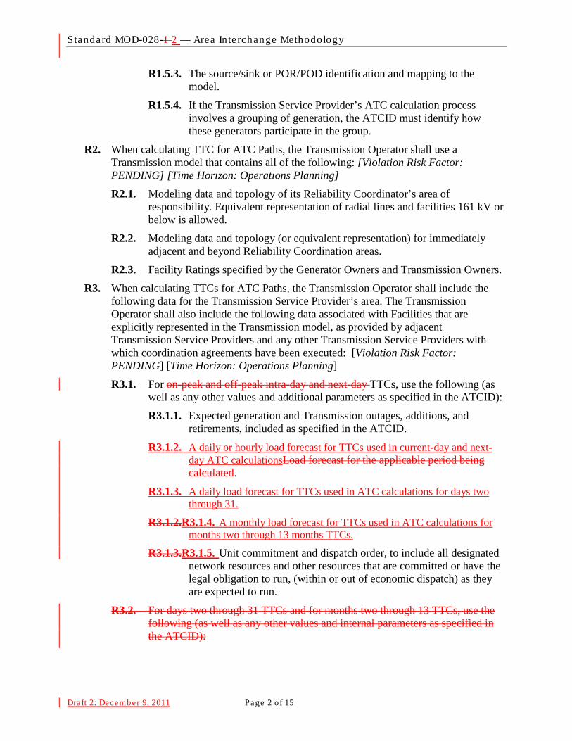
Standard MOD-028-1 2 — Area In te rchange Methodology
Draft 2: December 9, 2011 Page 2 o f 15
R1.5.3. The source/sink or POR/POD identification and mapping to the model.
R1.5.4. If the Transmission Service Provider’s ATC calculation process involves a grouping of generation, the ATCID must identify how these generators participate in the group.
R2. When calculating TTC for ATC Paths, the Transmission Operator shall use a Transmission model that contains all of the following: [Violation Risk Factor: PENDING] [Time Horizon: Operations Planning] R2.1. Modeling data and topology of its Reliability Coordinator’s area of
responsibility. Equivalent representation of radial lines and facilities 161 kV or below is allowed.
R2.2. Modeling data and topology (or equivalent representation) for immediately adjacent and beyond Reliability Coordination areas.
R2.3. Facility Ratings specified by the Generator Owners and Transmission Owners.
R3. When calculating TTCs for ATC Paths, the Transmission Operator shall include the following data for the Transmission Service Provider’s area. The Transmission Operator shall also include the following data associated with Facilities that are explicitly represented in the Transmission model, as provided by adjacent Transmission Service Providers and any other Transmission Service Providers with which coordination agreements have been executed: [Violation Risk Factor: PENDING] [Time Horizon: Operations Planning]
R3.1. For on-peak and off-peak intra-day and next-day TTCs, use the following (as well as any other values and additional parameters as specified in the ATCID):
R3.1.1. Expected generation and Transmission outages, additions, and retirements, included as specified in the ATCID.
R3.1.2. A daily or hourly load forecast for TTCs used in current-day and next-day ATC calculationsLoad forecast for the applicable period being calculated.
R3.1.3. A daily load forecast for TTCs used in ATC calculations for days two through 31.
R3.1.2.R3.1.4. A monthly load forecast for TTCs used in ATC calculations for months two through 13 months TTCs.
R3.1.3.R3.1.5. Unit commitment and dispatch order, to include all designated network resources and other resources that are committed or have the legal obligation to run, (within or out of economic dispatch) as they are expected to run.
R3.2. For days two through 31 TTCs and for months two through 13 TTCs, use the following (as well as any other values and internal parameters as specified in the ATCID):
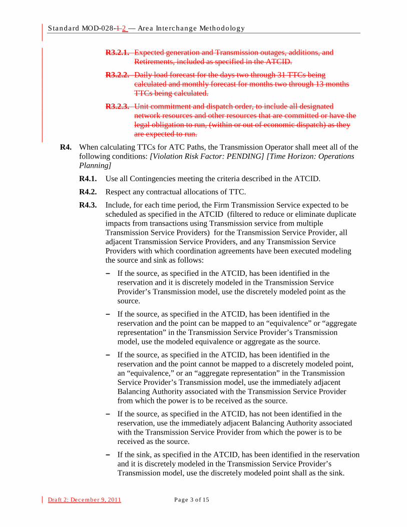
Standard MOD-028-1 2 — Area In te rchange Methodology
Draft 2: December 9, 2011 Page 3 o f 15
R3.2.1. Expected generation and Transmission outages, additions, and Retirements, included as specified in the ATCID.
R3.2.2. Daily load forecast for the days two through 31 TTCs being calculated and monthly forecast for months two through 13 months TTCs being calculated.
R3.2.3. Unit commitment and dispatch order, to include all designated network resources and other resources that are committed or have the legal obligation to run, (within or out of economic dispatch) as they are expected to run.
R4. When calculating TTCs for ATC Paths, the Transmission Operator shall meet all of the following conditions: [Violation Risk Factor: PENDING] [Time Horizon: Operations Planning] R4.1. Use all Contingencies meeting the criteria described in the ATCID.
R4.2. Respect any contractual allocations of TTC.
R4.3. Include, for each time period, the Firm Transmission Service expected to be scheduled as specified in the ATCID (filtered to reduce or eliminate duplicate impacts from transactions using Transmission service from multiple Transmission Service Providers) for the Transmission Service Provider, all adjacent Transmission Service Providers, and any Transmission Service Providers with which coordination agreements have been executed modeling the source and sink as follows:
- If the source, as specified in the ATCID, has been identified in the reservation and it is discretely modeled in the Transmission Service Provider’s Transmission model, use the discretely modeled point as the source.
- If the source, as specified in the ATCID, has been identified in the reservation and the point can be mapped to an “equivalence” or “aggregate representation” in the Transmission Service Provider’s Transmission model, use the modeled equivalence or aggregate as the source.
- If the source, as specified in the ATCID, has been identified in the reservation and the point cannot be mapped to a discretely modeled point, an “equivalence,” or an “aggregate representation” in the Transmission Service Provider’s Transmission model, use the immediately adjacent Balancing Authority associated with the Transmission Service Provider from which the power is to be received as the source.
- If the source, as specified in the ATCID, has not been identified in the reservation, use the immediately adjacent Balancing Authority associated with the Transmission Service Provider from which the power is to be received as the source.
- If the sink, as specified in the ATCID, has been identified in the reservation and it is discretely modeled in the Transmission Service Provider’s Transmission model, use the discretely modeled point shall as the sink.

Standard MOD-028-1 2 — Area In te rchange Methodology
Draft 2: December 9, 2011 Page 4 o f 15
- If the sink, as specified in the ATCID, has been identified in the reservation and the point can be mapped to an “equivalence” or “aggregate representation” in the Transmission Service Provider’s Transmission model, use the modeled equivalence or aggregate as the sink.
- If the sink, as specified in the ATCID, has been identified in the reservation and the point can not be mapped to a discretely modeled point, an “equivalence,” or an “aggregate representation” in the Transmission Service Provider’s Transmission model, use the immediately adjacent Balancing Authority associated with the Transmission Service Provider to which the power is to be delivered as the sink.
- If the sink, as specified in the ATCID, has not been identified in the reservation, use the immediately adjacent Balancing Authority associated with the Transmission Service Provider to which the power is being delivered as the sink.
R5. Each Transmission Operator shall establish TTC for each ATC Path as defined below: [Violation Risk Factor: PENDING] [Time Horizon: Operations Planning] R5.1. At least once within the seven calendar days prior to the specified period for
TTCs used in hourly and daily ATC calculations.
R5.2. At least once per calendar month for TTCs used in monthly ATC calculations.
R5.3. Within 24 hours of the unexpected outage of a 500 kV or higher transmission Facility or a transformer with a low-side voltage of 200 kV or higher for TTCs in effect during the anticipated duration of the outage, provided such outage is expected to last 24 hours or longer.
R6. Each Transmission Operator shall establish TTC for each ATC Path using the following process: [Violation Risk Factor: PENDING] [Time Horizon: Operations Planning] R6.1. Determine the incremental Transfer Capability for each ATC Path by
increasing generation and/or decreasing load within the source Balancing Authority area and decreasing generation and/or increasing load within the sink Balancing Authority area until either:
- A System Operating Limit is reached on the Transmission Service Provider’s system, or
- A SOL is reached on any other adjacent system in the Transmission model that is not on the study path and the distribution factor is 5% or greater1
R6.2. If the limit in step R6.1 can not be reached by adjusting any combination of load or generation, then set the incremental Transfer Capability by the results of the case where the maximum adjustments were applied.
.
R6.3. Use (as the TTC) the lesser of:
1 The Transmission operator may honor distribution factors less than 5% if desired.

Standard MOD-028-1 2 — Area In te rchange Methodology
Draft 2: December 9, 2011 Page 5 o f 15
− The sum of the incremental Transfer Capability and the impacts of Firm Transmission Services, as specified in the Transmission Service Provider’s ATCID, that were included in the study model, or
− The sum of Facility Ratings of all ties comprising the ATC Path.
R6.4. For ATC Paths whose capacity uses jointly-owned or allocated Facilities, limit TTC for each Transmission Service Provider so the TTC does not exceed each Transmission Service Provider’s contractual rights.
R7. The Transmission Operator shall provide the Transmission Service Provider of that ATC Path with the most current value for TTC for that ATC Path no more than: [Violation Risk Factor: PENDING] [Time Horizon: Operations Planning]
R7.1. One calendar day after its determination for TTCs used in hourly and daily ATC calculations.
R7.2. Seven calendar days after its determination for TTCs used in monthly ATC calculations.
R8. When calculating Existing Transmission Commitments (ETCs) for firm commitments (ETCF
ETC
) for all time periods for an ATC Path the Transmission Service Provider shall use the following algorithm: [Violation Risk Factor: PENDING] [Time Horizon: Operations Planning]
F = NITSF + GFF + PTPF + RORF + OS
Where: F
NITSF is the firm capacity set aside for Network Integration Transmission Service (including the capacity used to serve bundled load within the Transmission Service Provider’s area with external sources) on ATC Paths that serve as interfaces with other Balancing Authorities.
GFF is the firm capacity set aside for Grandfathered Firm Transmission Service and contracts for energy and/or Transmission Service, where executed prior to the effective date of a Transmission Service Provider’s Open Access Transmission Tariff or safe harbor tariff on ATC Paths that serve as interfaces with other Balancing Authorities.
PTPF is the firm capacity reserved for confirmed Point-to-Point Transmission Service.
RORF is the capacity reserved for roll-over rights for Firm Transmission Service contracts granting Transmission Customers the right of first refusal to take or continue to take Transmission Service when the Transmission Customer’s Transmission Service contract expires or is eligible for renewal.
OSF is the firm capacity reserved for any other service(s), contract(s), or agreement(s) not specified above using Firm Transmission Service, including any other firm adjustments to reflect impacts from other ATC Paths of the Transmission Service Provider as specified in the ATCID.

Standard MOD-028-1 2 — Area In te rchange Methodology
Draft 2: December 9, 2011 Page 6 o f 15
R9. When calculating ETC for non-firm commitments (ETCNF
ETC
) for all time periods for an ATC Path the Transmission Service Provider shall use the following algorithm: [Violation Risk Factor: PENDING] [Time Horizon: Operations Planning]
NF = NITSNF + GFNF + PTPNF + OS
NF
Where: NITSNF is the non-firm capacity set aside for Network Integration Transmission
Service (i.e., secondary service , including the capacity used to serve bundled load within the Transmission Service Provider’s area with external sources) reserved on ATC Paths that serve as interfaces with other Balancing Authorities.
GFNF is the non-firm capacity reserved for Grandfathered Non-Firm Transmission Service and contracts for energy and/or Transmission Service, where executed prior to the effective date of a Transmission Service Provider’s Open Access Transmission Tariff or safe harbor tariff on ATC Paths that serve as interfaces with other Balancing Authorities.
PTPNF is non-firm capacity reserved for confirmed Point-to-Point Transmission Service.
OSNF is the non-firm capacity reserved for any other service(s), contract(s), or agreement(s) not specified above using Non-Firm Transmission Service, including any other firm adjustments to reflect impacts from other ATC Paths of the Transmission Service Provider as specified in the ATCID.
R10. When calculating firm ATC for an ATC Path for a specified period, the Transmission Service Provider shall utilize the following algorithm: [Violation Risk Factor: PENDING] [Time Horizon: Operations Planning]
ATCF = TTC – ETCF – CBM – TRM + PostbacksF + counterflowsF
Where: ATCF is the firm Available Transfer Capability for the ATC Path for that period.
TTC is the Total Transfer Capability of the ATC Path for that period.
ETCF is the sum of existing firm Transmission commitments for the ATC Path during that period.
CBM is the Capacity Benefit Margin for the ATC Path during that period.
TRM is the Transmission Reliability Margin for the ATC Path during that period.
PostbacksF are changes to firm ATC due to a change in the use of Transmission Service for that period, as defined in Business Practices.
counterflowsF are adjustments to firm ATC as determined by the Transmission Service Provider and specified in the ATCID.
R11. When calculating non-firm ATC for a ATC Path for a specified period, the Transmission Service Provider shall use the following algorithm: [Violation Risk Factor: Lower] [Time Horizon: Operations Planning]
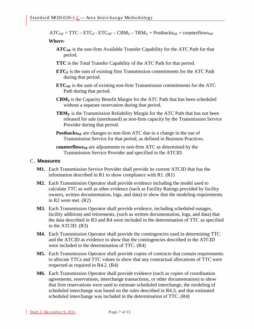
Standard MOD-028-1 2 — Area In te rchange Methodology
Draft 2: December 9, 2011 Page 7 o f 15
ATCNF = TTC – ETCF - ETCNF – CBMS – TRMU + PostbacksNF + counterflowsNF
Where: ATCNF is the non-firm Available Transfer Capability for the ATC Path for that
period.
TTC is the Total Transfer Capability of the ATC Path for that period.
ETCF is the sum of existing firm Transmission commitments for the ATC Path during that period.
ETCNF is the sum of existing non-firm Transmission commitments for the ATC Path during that period.
CBMS is the Capacity Benefit Margin for the ATC Path that has been scheduled without a separate reservation during that period.
TRMU is the Transmission Reliability Margin for the ATC Path that has not been released for sale (unreleased) as non-firm capacity by the Transmission Service Provider during that period.
PostbacksNF are changes to non-firm ATC due to a change in the use of Transmission Service for that period, as defined in Business Practices.
counterflowsNF are adjustments to non-firm ATC as determined by the Transmission Service Provider and specified in the ATCID.
C. Measures M1. Each Transmission Service Provider shall provide its current ATCID that has the
information described in R1 to show compliance with R1. (R1)
M2. Each Transmission Operator shall provide evidence including the model used to calculate TTC as well as other evidence (such as Facility Ratings provided by facility owners, written documentation, logs, and data) to show that the modeling requirements in R2 were met. (R2)
M3. Each Transmission Operator shall provide evidence, including scheduled outages, facility additions and retirements, (such as written documentation, logs, and data) that the data described in R3 and R4 were included in the determination of TTC as specified in the ATCID. (R3)
M4. Each Transmission Operator shall provide the contingencies used in determining TTC and the ATCID as evidence to show that the contingencies described in the ATCID were included in the determination of TTC. (R4)
M5. Each Transmission Operator shall provide copies of contracts that contain requirements to allocate TTCs and TTC values to show that any contractual allocations of TTC were respected as required in R4.2. (R4)
M6. Each Transmission Operator shall provide evidence (such as copies of coordination agreements, reservations, interchange transactions, or other documentation) to show that firm reservations were used to estimate scheduled interchange, the modeling of scheduled interchange was based on the rules described in R4.3, and that estimated scheduled interchange was included in the determination of TTC. (R4)
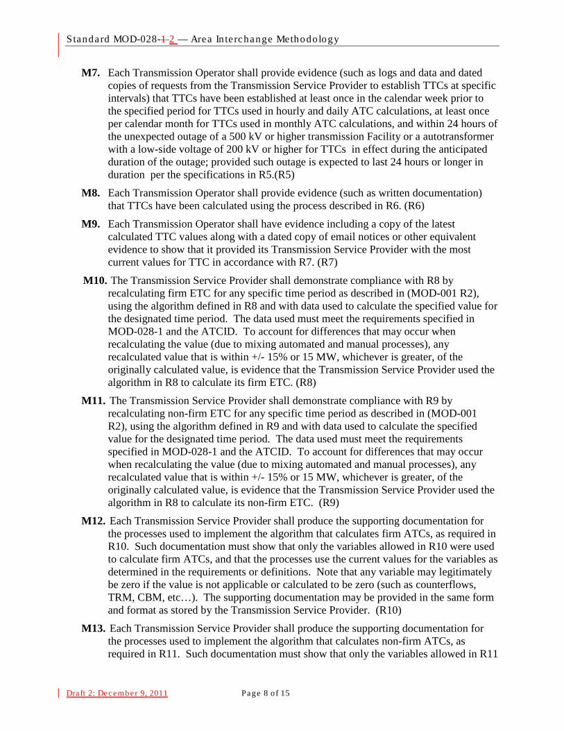
Standard MOD-028-1 2 — Area In te rchange Methodology
Draft 2: December 9, 2011 Page 8 o f 15
M7. Each Transmission Operator shall provide evidence (such as logs and data and dated copies of requests from the Transmission Service Provider to establish TTCs at specific intervals) that TTCs have been established at least once in the calendar week prior to the specified period for TTCs used in hourly and daily ATC calculations, at least once per calendar month for TTCs used in monthly ATC calculations, and within 24 hours of the unexpected outage of a 500 kV or higher transmission Facility or a autotransformer with a low-side voltage of 200 kV or higher for TTCs in effect during the anticipated duration of the outage; provided such outage is expected to last 24 hours or longer in duration per the specifications in R5.(R5)
M8. Each Transmission Operator shall provide evidence (such as written documentation) that TTCs have been calculated using the process described in R6. (R6)
M9. Each Transmission Operator shall have evidence including a copy of the latest calculated TTC values along with a dated copy of email notices or other equivalent evidence to show that it provided its Transmission Service Provider with the most current values for TTC in accordance with R7. (R7)
M10. The Transmission Service Provider shall demonstrate compliance with R8 by recalculating firm ETC
M11. The Transmission Service Provider shall demonstrate compliance with R9 by recalculating non-firm ETC for any specific time period as described in (MOD-001 R2), using the algorithm defined in R9 and with data used to calculate the specified value for the designated time period. The data used must meet the requirements specified in MOD-028-1 and the ATCID. To account for differences that may occur when recalculating the value (due to mixing automated and manual processes), any recalculated value that is within +/- 15% or 15 MW, whichever is greater, of the originally calculated value, is evidence that the Transmission Service Provider used the algorithm in R8 to calculate its non-firm ETC. (R9)
for any specific time period as described in (MOD-001 R2), using the algorithm defined in R8 and with data used to calculate the specified value for the designated time period. The data used must meet the requirements specified in MOD-028-1 and the ATCID. To account for differences that may occur when recalculating the value (due to mixing automated and manual processes), any recalculated value that is within +/- 15% or 15 MW, whichever is greater, of the originally calculated value, is evidence that the Transmission Service Provider used the algorithm in R8 to calculate its firm ETC. (R8)
M12. Each Transmission Service Provider shall produce the supporting documentation for the processes used to implement the algorithm that calculates firm ATCs, as required in R10. Such documentation must show that only the variables allowed in R10 were used to calculate firm ATCs, and that the processes use the current values for the variables as determined in the requirements or definitions. Note that any variable may legitimately be zero if the value is not applicable or calculated to be zero (such as counterflows, TRM, CBM, etc…). The supporting documentation may be provided in the same form and format as stored by the Transmission Service Provider. (R10)
M13. Each Transmission Service Provider shall produce the supporting documentation for the processes used to implement the algorithm that calculates non-firm ATCs, as required in R11. Such documentation must show that only the variables allowed in R11
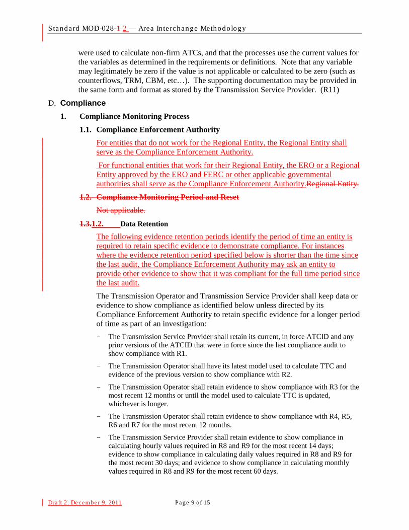
Standard MOD-028-1 2 — Area In te rchange Methodology
Draft 2: December 9, 2011 Page 9 o f 15
were used to calculate non-firm ATCs, and that the processes use the current values for the variables as determined in the requirements or definitions. Note that any variable may legitimately be zero if the value is not applicable or calculated to be zero (such as counterflows, TRM, CBM, etc…). The supporting documentation may be provided in the same form and format as stored by the Transmission Service Provider. (R11)
D. Compliance 1. Compliance Monitoring Process
1.1. Compliance Enforcement Authority For entities that do not work for the Regional Entity, the Regional Entity shall serve as the Compliance Enforcement Authority.
For functional entities that work for their Regional Entity, the ERO or a Regional Entity approved by the ERO and FERC or other applicable governmental authorities shall serve as the Compliance Enforcement Authority.Regional Entity.
1.2. Compliance Monitoring Period and Reset Not applicable.
1.3.1.2. Data Retention
The following evidence retention periods identify the period of time an entity is required to retain specific evidence to demonstrate compliance. For instances where the evidence retention period specified below is shorter than the time since the last audit, the Compliance Enforcement Authority may ask an entity to provide other evidence to show that it was compliant for the full time period since the last audit.
The Transmission Operator and Transmission Service Provider shall keep data or evidence to show compliance as identified below unless directed by its Compliance Enforcement Authority to retain specific evidence for a longer period of time as part of an investigation:
- The Transmission Service Provider shall retain its current, in force ATCID and any prior versions of the ATCID that were in force since the last compliance audit to show compliance with R1.
- The Transmission Operator shall have its latest model used to calculate TTC and evidence of the previous version to show compliance with R2.
- The Transmission Operator shall retain evidence to show compliance with R3 for the most recent 12 months or until the model used to calculate TTC is updated, whichever is longer.
- The Transmission Operator shall retain evidence to show compliance with R4, R5, R6 and R7 for the most recent 12 months.
- The Transmission Service Provider shall retain evidence to show compliance in calculating hourly values required in R8 and R9 for the most recent 14 days; evidence to show compliance in calculating daily values required in R8 and R9 for the most recent 30 days; and evidence to show compliance in calculating monthly values required in R8 and R9 for the most recent 60 days.
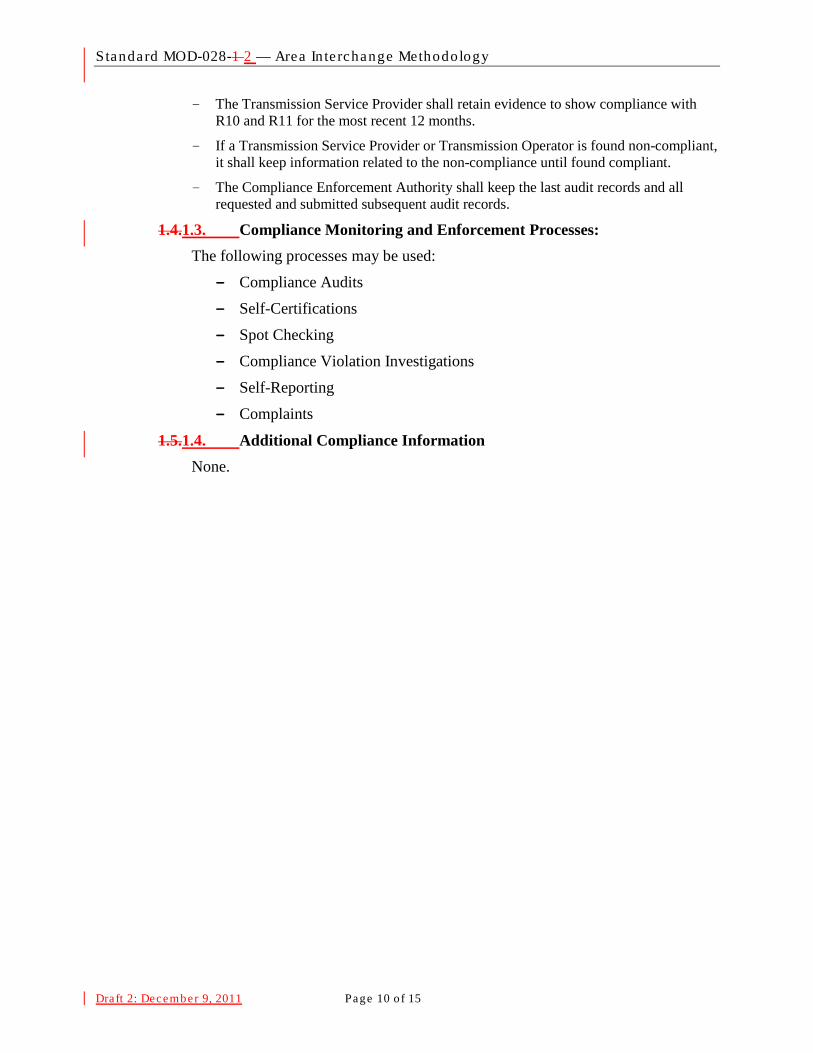
Standard MOD-028-1 2 — Area In te rchange Methodology
Draft 2: December 9, 2011 Page 10 of 15
- The Transmission Service Provider shall retain evidence to show compliance with R10 and R11 for the most recent 12 months.
- If a Transmission Service Provider or Transmission Operator is found non-compliant, it shall keep information related to the non-compliance until found compliant.
- The Compliance Enforcement Authority shall keep the last audit records and all requested and submitted subsequent audit records.
1.4.1.3. Compliance Monitoring and Enforcement Processes: The following processes may be used:
- Compliance Audits
- Self-Certifications
- Spot Checking
- Compliance Violation Investigations
- Self-Reporting
- Complaints
1.5.1.4. Additional Compliance Information None.
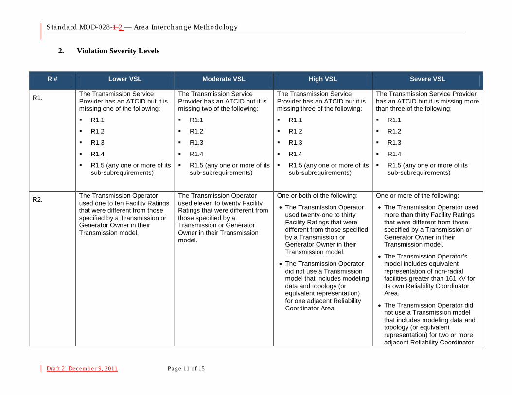
Standard MOD-028-1 2 — Area In te rchange Methodology
Draft 2: December 9, 2011 Page 11 of 15
2. Violation Severity Levels
R # Lower VSL Moderate VSL High VSL Severe VSL
R1. The Transmission Service Provider has an ATCID but it is missing one of the following:
R1.1
R1.2
R1.3
R1.4
R1.5 (any one or more of its sub-subrequirements)
The Transmission Service Provider has an ATCID but it is missing two of the following:
R1.1
R1.2
R1.3
R1.4
R1.5 (any one or more of its sub-subrequirements)
The Transmission Service Provider has an ATCID but it is missing three of the following:
R1.1
R1.2
R1.3
R1.4
R1.5 (any one or more of its sub-subrequirements)
The Transmission Service Provider has an ATCID but it is missing more than three of the following:
R1.1
R1.2
R1.3
R1.4
R1.5 (any one or more of its sub-subrequirements)
R2. The Transmission Operator used one to ten Facility Ratings that were different from those specified by a Transmission or Generator Owner in their Transmission model.
The Transmission Operator used eleven to twenty Facility Ratings that were different from those specified by a Transmission or Generator Owner in their Transmission model.
One or both of the following:
• The Transmission Operator used twenty-one to thirty Facility Ratings that were different from those specified by a Transmission or Generator Owner in their Transmission model.
• The Transmission Operator did not use a Transmission model that includes modeling data and topology (or equivalent representation) for one adjacent Reliability Coordinator Area.
One or more of the following:
• The Transmission Operator used more than thirty Facility Ratings that were different from those specified by a Transmission or Generator Owner in their Transmission model.
• The Transmission Operator’s model includes equivalent representation of non-radial facilities greater than 161 kV for its own Reliability Coordinator Area.
• The Transmission Operator did not use a Transmission model that includes modeling data and topology (or equivalent representation) for two or more adjacent Reliability Coordinator
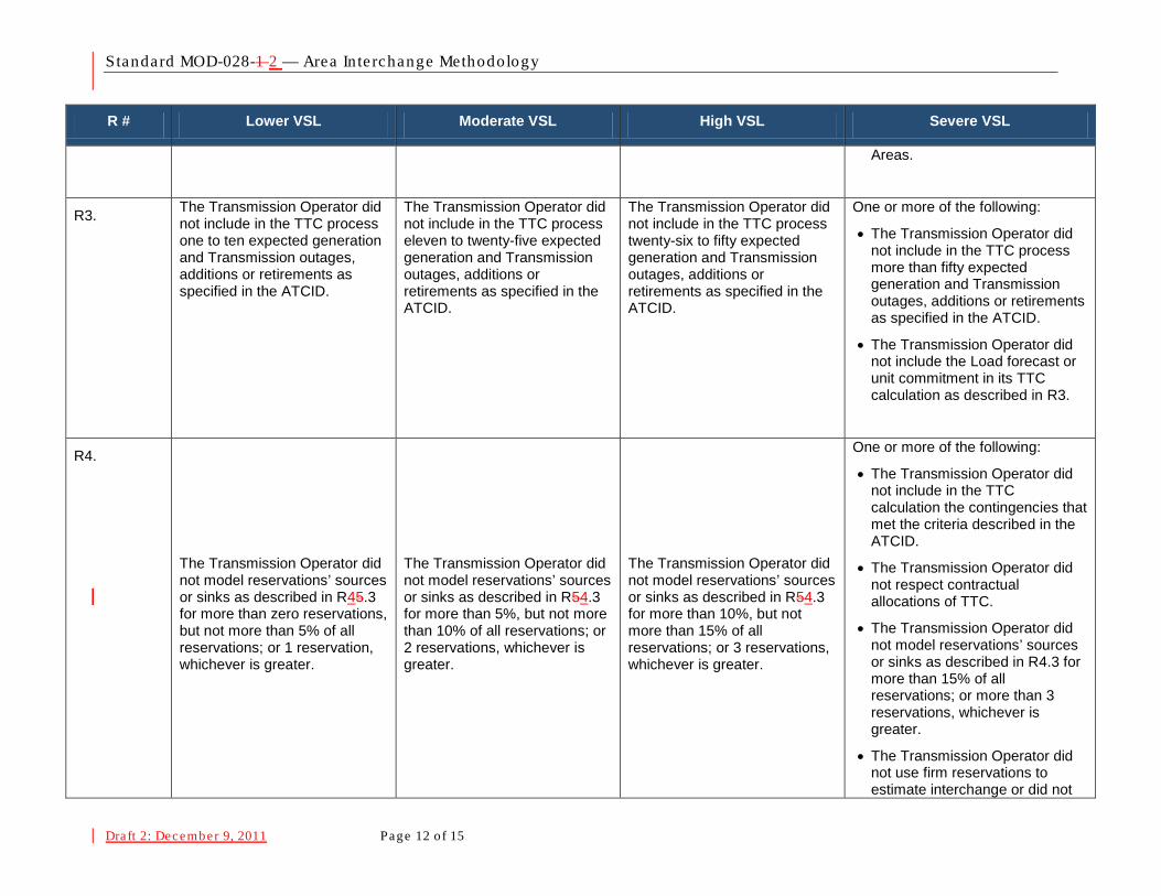
Standard MOD-028-1 2 — Area In te rchange Methodology
Draft 2: December 9, 2011 Page 12 of 15
R # Lower VSL Moderate VSL High VSL Severe VSL
Areas.
R3. The Transmission Operator did not include in the TTC process one to ten expected generation and Transmission outages, additions or retirements as specified in the ATCID.
The Transmission Operator did not include in the TTC process eleven to twenty-five expected generation and Transmission outages, additions or retirements as specified in the ATCID.
The Transmission Operator did not include in the TTC process twenty-six to fifty expected generation and Transmission outages, additions or retirements as specified in the ATCID.
One or more of the following:
• The Transmission Operator did not include in the TTC process more than fifty expected generation and Transmission outages, additions or retirements as specified in the ATCID.
• The Transmission Operator did not include the Load forecast or unit commitment in its TTC calculation as described in R3.
R4.
The Transmission Operator did not model reservations’ sources or sinks as described in R45.3 for more than zero reservations, but not more than 5% of all reservations; or 1 reservation, whichever is greater.
The Transmission Operator did not model reservations’ sources or sinks as described in R54.3 for more than 5%, but not more than 10% of all reservations; or 2 reservations, whichever is greater.
The Transmission Operator did not model reservations’ sources or sinks as described in R54.3 for more than 10%, but not more than 15% of all reservations; or 3 reservations, whichever is greater.
One or more of the following:
• The Transmission Operator did not include in the TTC calculation the contingencies that met the criteria described in the ATCID.
• The Transmission Operator did not respect contractual allocations of TTC.
• The Transmission Operator did not model reservations’ sources or sinks as described in R4.3 for more than 15% of all reservations; or more than 3 reservations, whichever is greater.
• The Transmission Operator did not use firm reservations to estimate interchange or did not

Standard MOD-028-1 2 — Area In te rchange Methodology
Draft 2: December 9, 2011 Page 13 of 15
R # Lower VSL Moderate VSL High VSL Severe VSL
utilize that estimate in the TTC calculation as described in R4.3.
R5. One or more of the following:
• The Transmission Operator did not establish TTCs for use in hourly or daily ATCs within 7 calendar days but did establish the values within 10 calendar days
• The Transmission Operator did not establish TTCs for use in monthly ATCs during a calendar month but did establish the values within the next consecutive calendar month
One or more of the following:
• The Transmission Operator did not establish TTCs for use in hourly or daily ATCs in 10 calendar days but did establish the values within 13 calendar days
• The Transmission Operator did not establish TTCs for use in monthly ATCs during a two consecutive calendar month period but did establish the values within the third consecutive calendar month
One or more of the following:
• The Transmission Operator did not establish TTCs for used in hourly or daily ATCs in 13 calendar days but did establish the values within 16 calendar days
• The Transmission Operator did not establish TTCs for use in monthly ATCs during a three consecutive calendar month period but did establish the values within the fourth consecutive calendar month
One or more of the following:
• The Transmission Operator did not establish TTCs for used in hourly or daily ATCs in 16 calendar days
• The Transmission Operator did not establish TTCs for use in monthly ATCs during a four or more consecutive calendar month period
• The Transmission Operator did not establish TTCs within 24 hrs of the triggers defined in R5.3
R6. N/A N/A N/A
The Transmission Operator did not calculate TTCs per the process specified in R6.
R7. One or more of the following:
• The Transmission Operator provided its Transmission Service Provider with its ATC Path TTCs used in hourly or daily ATC calculations more than one calendar day after their determination, but not been more than two calendar days after their determination.
• The Transmission Operator
One or more of the following:
• The Transmission Operator provided its Transmission Service Provider with its ATC Path TTCs used in hourly or daily ATC calculations more than two calendar days after their determination, but not been more than three calendar days after their determination.
• The Transmission Operator
One or more of the following:
• The Transmission Operator provided its Transmission Service Provider with its ATC Path TTCs used in hourly or daily ATC calculations more than three calendar days after their determination, but not been more than four calendar days after their determination.
• The Transmission Operator
One or more of the following:
• The Transmission Operator provided its Transmission Service Provider with its ATC Path TTCs used in hourly or daily ATC calculations more than four calendar days after their determination.
• The Transmission Operator did not provide its Transmission Service Provider with its ATC Path TTCs used in hourly or
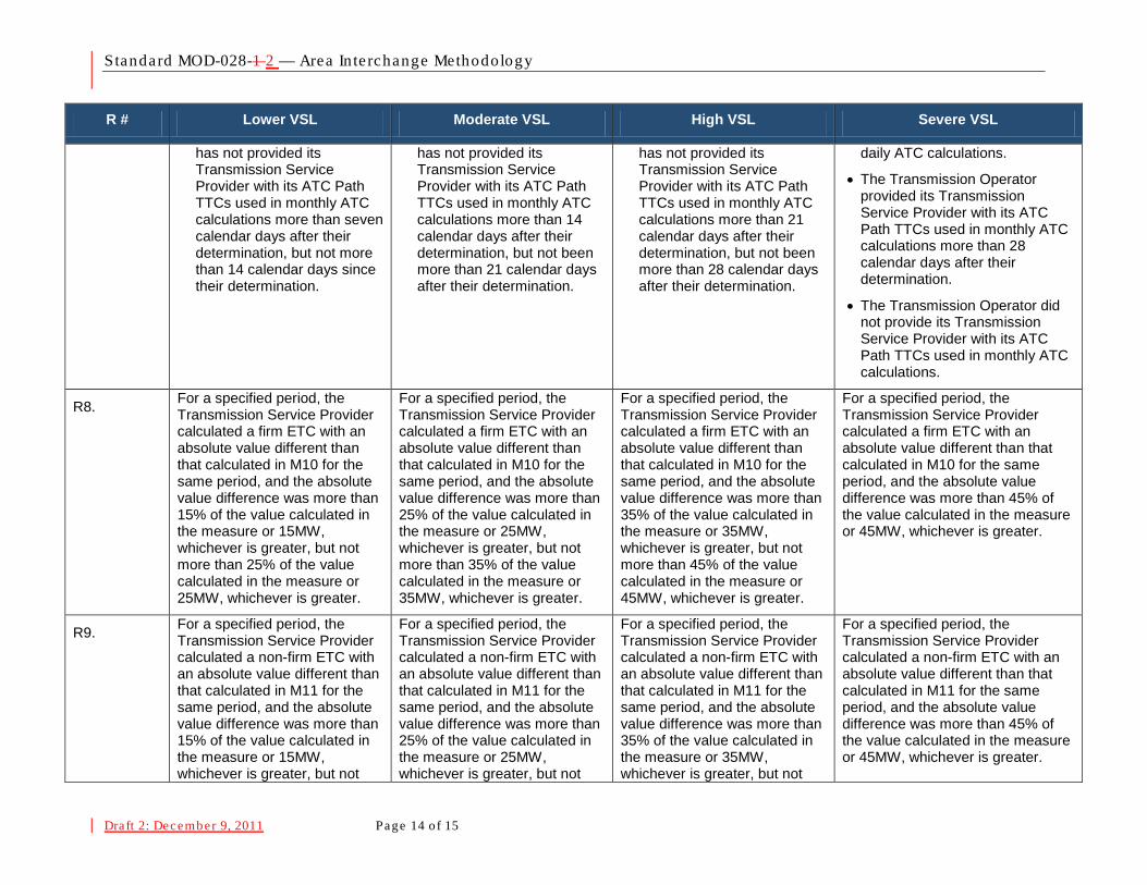
Standard MOD-028-1 2 — Area In te rchange Methodology
Draft 2: December 9, 2011 Page 14 of 15
R # Lower VSL Moderate VSL High VSL Severe VSL
has not provided its Transmission Service Provider with its ATC Path TTCs used in monthly ATC calculations more than seven calendar days after their determination, but not more than 14 calendar days since their determination.
has not provided its Transmission Service Provider with its ATC Path TTCs used in monthly ATC calculations more than 14 calendar days after their determination, but not been more than 21 calendar days after their determination.
has not provided its Transmission Service Provider with its ATC Path TTCs used in monthly ATC calculations more than 21 calendar days after their determination, but not been more than 28 calendar days after their determination.
daily ATC calculations.
• The Transmission Operator provided its Transmission Service Provider with its ATC Path TTCs used in monthly ATC calculations more than 28 calendar days after their determination.
• The Transmission Operator did not provide its Transmission Service Provider with its ATC Path TTCs used in monthly ATC calculations.
R8. For a specified period, the Transmission Service Provider calculated a firm ETC with an absolute value different than that calculated in M10 for the same period, and the absolute value difference was more than 15% of the value calculated in the measure or 15MW, whichever is greater, but not more than 25% of the value calculated in the measure or 25MW, whichever is greater.
For a specified period, the Transmission Service Provider calculated a firm ETC with an absolute value different than that calculated in M10 for the same period, and the absolute value difference was more than 25% of the value calculated in the measure or 25MW, whichever is greater, but not more than 35% of the value calculated in the measure or 35MW, whichever is greater.
For a specified period, the Transmission Service Provider calculated a firm ETC with an absolute value different than that calculated in M10 for the same period, and the absolute value difference was more than 35% of the value calculated in the measure or 35MW, whichever is greater, but not more than 45% of the value calculated in the measure or 45MW, whichever is greater.
For a specified period, the Transmission Service Provider calculated a firm ETC with an absolute value different than that calculated in M10 for the same period, and the absolute value difference was more than 45% of the value calculated in the measure or 45MW, whichever is greater.
R9. For a specified period, the Transmission Service Provider calculated a non-firm ETC with an absolute value different than that calculated in M11 for the same period, and the absolute value difference was more than 15% of the value calculated in the measure or 15MW, whichever is greater, but not
For a specified period, the Transmission Service Provider calculated a non-firm ETC with an absolute value different than that calculated in M11 for the same period, and the absolute value difference was more than 25% of the value calculated in the measure or 25MW, whichever is greater, but not
For a specified period, the Transmission Service Provider calculated a non-firm ETC with an absolute value different than that calculated in M11 for the same period, and the absolute value difference was more than 35% of the value calculated in the measure or 35MW, whichever is greater, but not
For a specified period, the Transmission Service Provider calculated a non-firm ETC with an absolute value different than that calculated in M11 for the same period, and the absolute value difference was more than 45% of the value calculated in the measure or 45MW, whichever is greater.
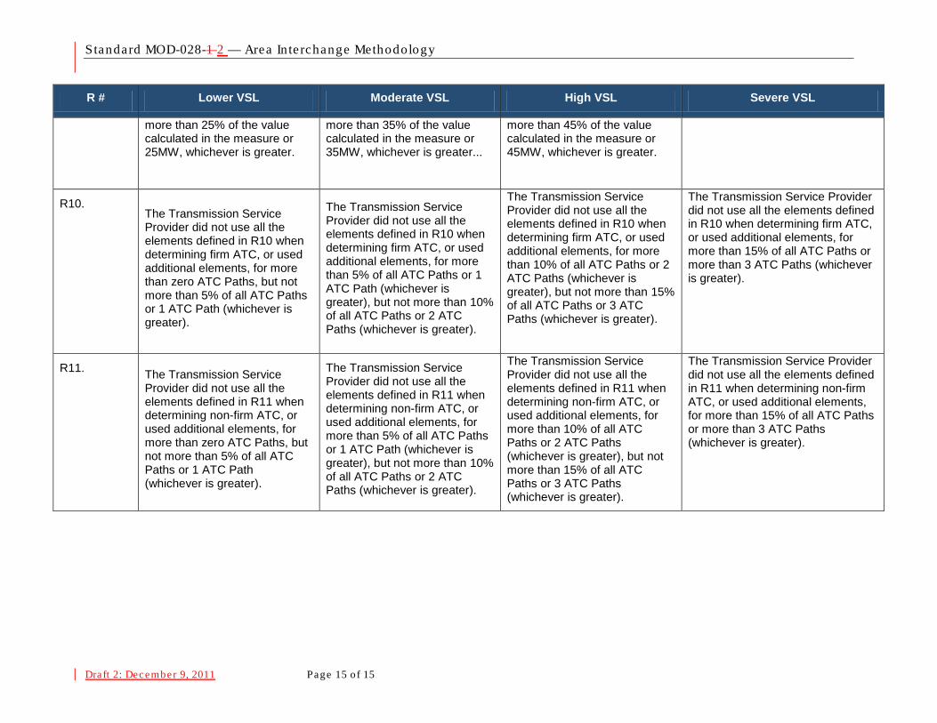
Standard MOD-028-1 2 — Area In te rchange Methodology
Draft 2: December 9, 2011 Page 15 of 15
R # Lower VSL Moderate VSL High VSL Severe VSL
more than 25% of the value calculated in the measure or 25MW, whichever is greater.
more than 35% of the value calculated in the measure or 35MW, whichever is greater...
more than 45% of the value calculated in the measure or 45MW, whichever is greater.
R10. The Transmission Service Provider did not use all the elements defined in R10 when determining firm ATC, or used additional elements, for more than zero ATC Paths, but not more than 5% of all ATC Paths or 1 ATC Path (whichever is greater).
The Transmission Service Provider did not use all the elements defined in R10 when determining firm ATC, or used additional elements, for more than 5% of all ATC Paths or 1 ATC Path (whichever is greater), but not more than 10% of all ATC Paths or 2 ATC Paths (whichever is greater).
The Transmission Service Provider did not use all the elements defined in R10 when determining firm ATC, or used additional elements, for more than 10% of all ATC Paths or 2 ATC Paths (whichever is greater), but not more than 15% of all ATC Paths or 3 ATC Paths (whichever is greater).
The Transmission Service Provider did not use all the elements defined in R10 when determining firm ATC, or used additional elements, for more than 15% of all ATC Paths or more than 3 ATC Paths (whichever is greater).
R11. The Transmission Service Provider did not use all the elements defined in R11 when determining non-firm ATC, or used additional elements, for more than zero ATC Paths, but not more than 5% of all ATC Paths or 1 ATC Path (whichever is greater).
The Transmission Service Provider did not use all the elements defined in R11 when determining non-firm ATC, or used additional elements, for more than 5% of all ATC Paths or 1 ATC Path (whichever is greater), but not more than 10% of all ATC Paths or 2 ATC Paths (whichever is greater).
The Transmission Service Provider did not use all the elements defined in R11 when determining non-firm ATC, or used additional elements, for more than 10% of all ATC Paths or 2 ATC Paths (whichever is greater), but not more than 15% of all ATC Paths or 3 ATC Paths (whichever is greater).
The Transmission Service Provider did not use all the elements defined in R11 when determining non-firm ATC, or used additional elements, for more than 15% of all ATC Paths or more than 3 ATC Paths (whichever is greater).

Standard MOD-028-2 — Area In te rchange Methodology
Draft 1: Augus t 302: December 9, 2011 Page 1 o f 15
A. Introduction 1. Title: Area Interchange Methodology 2. Number: MOD-028-2 3. Purpose: To increase consistency and reliability in the development and
documentation of Transfer Capability calculations for short-term use performed by entities using the Area Interchange Methodology to support analysis and system operations.
4. Applicability: 4.1. Each Transmission Operator that uses the Area Interchange Methodology to
calculate Total Transfer Capabilities (TTCs) for ATC Paths.
4.2. Each Transmission Service Provider that uses the Area Interchange Methodology to calculate Available Transfer Capabilities (ATCs) for ATC Paths.
5. Proposed Effective Date: In those jurisdictions where regulatory approval is required, this standard shall become effective on the first day of the first calendar quarter after applicable regulatory approval. In those jurisdictions where no regulatory approval is required, this standard shall become effective on the first day of the first calendar quarter after Board of Trustees approval.
B. Requirements R1. Each Transmission Service Provider shall include in its Available Transfer Capability
Implementation Document (ATCID), at a minimum, the following information relative to its methodology for determining Total Transfer Capability (TTC): [Violation Risk Factor: PENDING] [Time Horizon: Operations Planning] R1.1. Information describing how the selected methodology has been implemented,
in such detail that, given the same information used by the Transmission Operator, the results of the TTC calculations can be validated.
R1.2. A description of the manner in which the Transmission Operator will account for Interchange Schedules in the calculation of TTC.
R1.3. Any contractual obligations for allocation of TTC.
R1.4. A description of the manner in which Contingencies are identified for use in the TTC process.
R1.5. The following information on how source and sink for transmission service is accounted for in ATC calculations including:
R1.5.1. Define if the source used for Available Transfer Capability (ATC) calculations is obtained from the source field or the Point of Receipt (POR) field of the transmission reservation
R1.5.2. Define if the sink used for ATC calculations is obtained from the sink field or the Point of Delivery (POD) field of the transmission reservation

Standard MOD-028-2 — Area In te rchange Methodology
Draft 1: Augus t 302: December 9, 2011 Page 2 o f 15
R1.5.3. The source/sink or POR/POD identification and mapping to the model.
R1.5.4. If the Transmission Service Provider’s ATC calculation process involves a grouping of generation, the ATCID must identify how these generators participate in the group.
R2. When calculating TTC for ATC Paths, the Transmission Operator shall use a Transmission model that contains all of the following: [Violation Risk Factor: PENDING] [Time Horizon: Operations Planning] R2.1. Modeling data and topology of its Reliability Coordinator’s area of
responsibility. Equivalent representation of radial lines and facilities 161 kV or below is allowed.
R2.2. Modeling data and topology (or equivalent representation) for immediately adjacent and beyond Reliability Coordination areas.
R2.3. Facility Ratings specified by the Generator Owners and Transmission Owners.
R3. When calculating TTCs for ATC Paths, the Transmission Operator shall include the following data for the Transmission Service Provider’s area. The Transmission Operator shall also include the following data associated with Facilities that are explicitly represented in the Transmission model, as provided by adjacent Transmission Service Providers and any other Transmission Service Providers with which coordination agreements have been executed: [Violation Risk Factor: PENDING] [Time Horizon: Operations Planning]
R3.1. For TTCs, use the following (as well as any other values and additional parameters as specified in the ATCID):
R3.1.1. Expected generation and Transmission outages, additions, and retirements, included as specified in the ATCID.
R3.1.2. A daily or hourly load forecast for TTCs used in current-day and next-day ATC calculations.
R3.1.3. A Dailydaily load forecast for TTCs used in ATC calculations for days two through 31.
R3.1.4. A Monthlymonthly load forecast for TTCs used in ATC calculations for months two through 13 months TTCs.
R3.1.5. Unit commitment and dispatch order, to include all designated network resources and other resources that are committed or have the legal obligation to run, (within or out of economic dispatch) as they are expected to run.
R4. When calculating TTCs for ATC Paths, the Transmission Operator shall meet all of the following conditions: [Violation Risk Factor: PENDING] [Time Horizon: Operations Planning] R4.1. Use all Contingencies meeting the criteria described in the ATCID.
R4.2. Respect any contractual allocations of TTC.
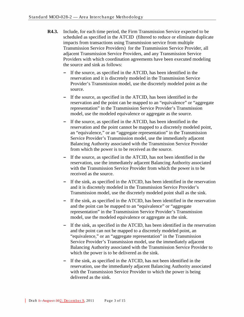
Standard MOD-028-2 — Area In te rchange Methodology
Draft 1: Augus t 302: December 9, 2011 Page 3 o f 15
R4.3. Include, for each time period, the Firm Transmission Service expected to be scheduled as specified in the ATCID (filtered to reduce or eliminate duplicate impacts from transactions using Transmission service from multiple Transmission Service Providers) for the Transmission Service Provider, all adjacent Transmission Service Providers, and any Transmission Service Providers with which coordination agreements have been executed modeling the source and sink as follows:
- If the source, as specified in the ATCID, has been identified in the reservation and it is discretely modeled in the Transmission Service Provider’s Transmission model, use the discretely modeled point as the source.
- If the source, as specified in the ATCID, has been identified in the reservation and the point can be mapped to an “equivalence” or “aggregate representation” in the Transmission Service Provider’s Transmission model, use the modeled equivalence or aggregate as the source.
- If the source, as specified in the ATCID, has been identified in the reservation and the point cannot be mapped to a discretely modeled point, an “equivalence,” or an “aggregate representation” in the Transmission Service Provider’s Transmission model, use the immediately adjacent Balancing Authority associated with the Transmission Service Provider from which the power is to be received as the source.
- If the source, as specified in the ATCID, has not been identified in the reservation, use the immediately adjacent Balancing Authority associated with the Transmission Service Provider from which the power is to be received as the source.
- If the sink, as specified in the ATCID, has been identified in the reservation and it is discretely modeled in the Transmission Service Provider’s Transmission model, use the discretely modeled point shall as the sink.
- If the sink, as specified in the ATCID, has been identified in the reservation and the point can be mapped to an “equivalence” or “aggregate representation” in the Transmission Service Provider’s Transmission model, use the modeled equivalence or aggregate as the sink.
- If the sink, as specified in the ATCID, has been identified in the reservation and the point can not be mapped to a discretely modeled point, an “equivalence,” or an “aggregate representation” in the Transmission Service Provider’s Transmission model, use the immediately adjacent Balancing Authority associated with the Transmission Service Provider to which the power is to be delivered as the sink.
- If the sink, as specified in the ATCID, has not been identified in the reservation, use the immediately adjacent Balancing Authority associated with the Transmission Service Provider to which the power is being delivered as the sink.

Standard MOD-028-2 — Area In te rchange Methodology
Draft 1: Augus t 302: December 9, 2011 Page 4 o f 15
R5. Each Transmission Operator shall establish TTC for each ATC Path as defined below: [Violation Risk Factor: PENDING] [Time Horizon: Operations Planning] R5.1. At least once within the seven calendar days prior to the specified period for
TTCs used in hourly and daily ATC calculations.
R5.2. At least once per calendar month for TTCs used in monthly ATC calculations.
R5.3. Within 24 hours of the unexpected outage of a 500 kV or higher transmission Facility or a transformer with a low-side voltage of 200 kV or higher for TTCs in effect during the anticipated duration of the outage, provided such outage is expected to last 24 hours or longer.
R6. Each Transmission Operator shall establish TTC for each ATC Path using the following process: [Violation Risk Factor: PENDING] [Time Horizon: Operations Planning] R6.1. Determine the incremental Transfer Capability for each ATC Path by
increasing generation and/or decreasing load within the source Balancing Authority area and decreasing generation and/or increasing load within the sink Balancing Authority area until either:
- A System Operating Limit is reached on the Transmission Service Provider’s system, or
- A SOL is reached on any other adjacent system in the Transmission model that is not on the study path and the distribution factor is 5% or greater1
R6.2. If the limit in step R6.1 can not be reached by adjusting any combination of load or generation, then set the incremental Transfer Capability by the results of the case where the maximum adjustments were applied.
.
R6.3. Use (as the TTC) the lesser of:
− The sum of the incremental Transfer Capability and the impacts of Firm Transmission Services, as specified in the Transmission Service Provider’s ATCID, that were included in the study model, or
− The sum of Facility Ratings of all ties comprising the ATC Path.
R6.4. For ATC Paths whose capacity uses jointly-owned or allocated Facilities, limit TTC for each Transmission Service Provider so the TTC does not exceed each Transmission Service Provider’s contractual rights.
R7. The Transmission Operator shall provide the Transmission Service Provider of that ATC Path with the most current value for TTC for that ATC Path no more than: [Violation Risk Factor: PENDING] [Time Horizon: Operations Planning]
R7.1. One calendar day after its determination for TTCs used in hourly and daily ATC calculations.
R7.2. Seven calendar days after its determination for TTCs used in monthly ATC calculations.
1 The Transmission operator may honor distribution factors less than 5% if desired.
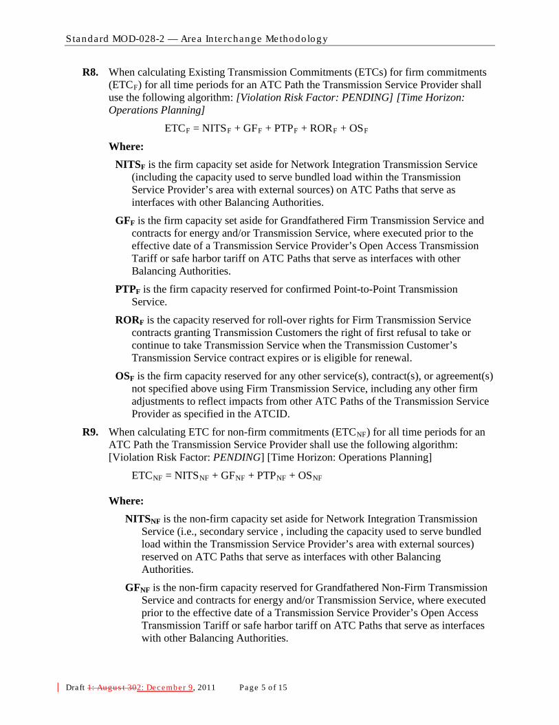
Standard MOD-028-2 — Area In te rchange Methodology
Draft 1: Augus t 302: December 9, 2011 Page 5 o f 15
R8. When calculating Existing Transmission Commitments (ETCs) for firm commitments (ETCF
ETC
) for all time periods for an ATC Path the Transmission Service Provider shall use the following algorithm: [Violation Risk Factor: PENDING] [Time Horizon: Operations Planning]
F = NITSF + GFF + PTPF + RORF + OS
Where: F
NITSF is the firm capacity set aside for Network Integration Transmission Service (including the capacity used to serve bundled load within the Transmission Service Provider’s area with external sources) on ATC Paths that serve as interfaces with other Balancing Authorities.
GFF is the firm capacity set aside for Grandfathered Firm Transmission Service and contracts for energy and/or Transmission Service, where executed prior to the effective date of a Transmission Service Provider’s Open Access Transmission Tariff or safe harbor tariff on ATC Paths that serve as interfaces with other Balancing Authorities.
PTPF is the firm capacity reserved for confirmed Point-to-Point Transmission Service.
RORF is the capacity reserved for roll-over rights for Firm Transmission Service contracts granting Transmission Customers the right of first refusal to take or continue to take Transmission Service when the Transmission Customer’s Transmission Service contract expires or is eligible for renewal.
OSF is the firm capacity reserved for any other service(s), contract(s), or agreement(s) not specified above using Firm Transmission Service, including any other firm adjustments to reflect impacts from other ATC Paths of the Transmission Service Provider as specified in the ATCID.
R9. When calculating ETC for non-firm commitments (ETCNF
ETC
) for all time periods for an ATC Path the Transmission Service Provider shall use the following algorithm: [Violation Risk Factor: PENDING] [Time Horizon: Operations Planning]
NF = NITSNF + GFNF + PTPNF + OS
NF
Where: NITSNF is the non-firm capacity set aside for Network Integration Transmission
Service (i.e., secondary service , including the capacity used to serve bundled load within the Transmission Service Provider’s area with external sources) reserved on ATC Paths that serve as interfaces with other Balancing Authorities.
GFNF is the non-firm capacity reserved for Grandfathered Non-Firm Transmission Service and contracts for energy and/or Transmission Service, where executed prior to the effective date of a Transmission Service Provider’s Open Access Transmission Tariff or safe harbor tariff on ATC Paths that serve as interfaces with other Balancing Authorities.
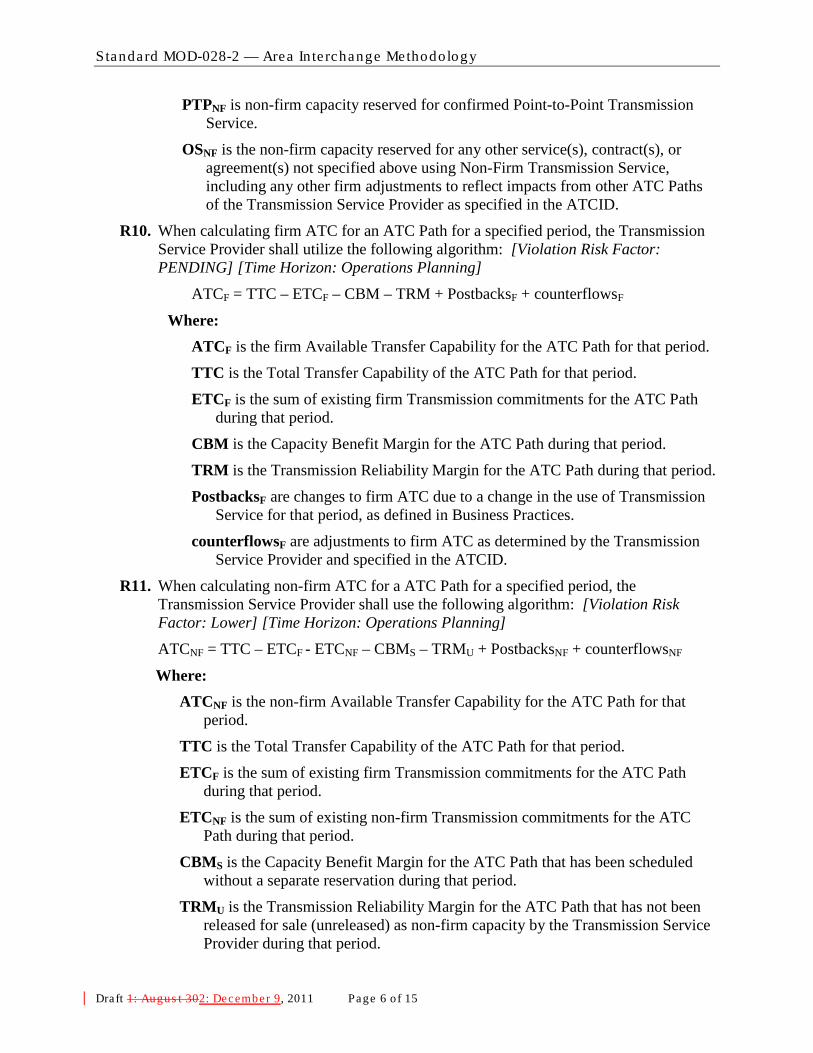
Standard MOD-028-2 — Area In te rchange Methodology
Draft 1: Augus t 302: December 9, 2011 Page 6 o f 15
PTPNF is non-firm capacity reserved for confirmed Point-to-Point Transmission Service.
OSNF is the non-firm capacity reserved for any other service(s), contract(s), or agreement(s) not specified above using Non-Firm Transmission Service, including any other firm adjustments to reflect impacts from other ATC Paths of the Transmission Service Provider as specified in the ATCID.
R10. When calculating firm ATC for an ATC Path for a specified period, the Transmission Service Provider shall utilize the following algorithm: [Violation Risk Factor: PENDING] [Time Horizon: Operations Planning]
ATCF = TTC – ETCF – CBM – TRM + PostbacksF + counterflowsF
Where: ATCF is the firm Available Transfer Capability for the ATC Path for that period.
TTC is the Total Transfer Capability of the ATC Path for that period.
ETCF is the sum of existing firm Transmission commitments for the ATC Path during that period.
CBM is the Capacity Benefit Margin for the ATC Path during that period.
TRM is the Transmission Reliability Margin for the ATC Path during that period.
PostbacksF are changes to firm ATC due to a change in the use of Transmission Service for that period, as defined in Business Practices.
counterflowsF are adjustments to firm ATC as determined by the Transmission Service Provider and specified in the ATCID.
R11. When calculating non-firm ATC for a ATC Path for a specified period, the Transmission Service Provider shall use the following algorithm: [Violation Risk Factor: Lower] [Time Horizon: Operations Planning] ATCNF = TTC – ETCF - ETCNF – CBMS – TRMU + PostbacksNF + counterflowsNF
Where: ATCNF is the non-firm Available Transfer Capability for the ATC Path for that
period.
TTC is the Total Transfer Capability of the ATC Path for that period.
ETCF is the sum of existing firm Transmission commitments for the ATC Path during that period.
ETCNF is the sum of existing non-firm Transmission commitments for the ATC Path during that period.
CBMS is the Capacity Benefit Margin for the ATC Path that has been scheduled without a separate reservation during that period.
TRMU is the Transmission Reliability Margin for the ATC Path that has not been released for sale (unreleased) as non-firm capacity by the Transmission Service Provider during that period.

Standard MOD-028-2 — Area In te rchange Methodology
Draft 1: Augus t 302: December 9, 2011 Page 7 o f 15
PostbacksNF are changes to non-firm ATC due to a change in the use of Transmission Service for that period, as defined in Business Practices.
counterflowsNF are adjustments to non-firm ATC as determined by the Transmission Service Provider and specified in the ATCID.
C. Measures M1. Each Transmission Service Provider shall provide its current ATCID that has the
information described in R1 to show compliance with R1. (R1)
M2. Each Transmission Operator shall provide evidence including the model used to calculate TTC as well as other evidence (such as Facility Ratings provided by facility owners, written documentation, logs, and data) to show that the modeling requirements in R2 were met. (R2)
M3. Each Transmission Operator shall provide evidence, including scheduled outages, facility additions and retirements, (such as written documentation, logs, and data) that the data described in R3 and R4 were included in the determination of TTC as specified in the ATCID. (R3)
M4. Each Transmission Operator shall provide the contingencies used in determining TTC and the ATCID as evidence to show that the contingencies described in the ATCID were included in the determination of TTC. (R4)
M5. Each Transmission Operator shall provide copies of contracts that contain requirements to allocate TTCs and TTC values to show that any contractual allocations of TTC were respected as required in R4.2. (R4)
M6. Each Transmission Operator shall provide evidence (such as copies of coordination agreements, reservations, interchange transactions, or other documentation) to show that firm reservations were used to estimate scheduled interchange, the modeling of scheduled interchange was based on the rules described in R4.3, and that estimated scheduled interchange was included in the determination of TTC. (R4)
M7. Each Transmission Operator shall provide evidence (such as logs and data and dated copies of requests from the Transmission Service Provider to establish TTCs at specific intervals) that TTCs have been established at least once in the calendar week prior to the specified period for TTCs used in hourly and daily ATC calculations, at least once per calendar month for TTCs used in monthly ATC calculations, and within 24 hours of the unexpected outage of a 500 kV or higher transmission Facility or a autotransformer with a low-side voltage of 200 kV or higher for TTCs in effect during the anticipated duration of the outage; provided such outage is expected to last 24 hours or longer in duration per the specifications in R5.(R5)
M8. Each Transmission Operator shall provide evidence (such as written documentation) that TTCs have been calculated using the process described in R6. (R6)
M9. Each Transmission Operator shall have evidence including a copy of the latest calculated TTC values along with a dated copy of email notices or other equivalent evidence to show that it provided its Transmission Service Provider with the most current values for TTC in accordance with R7. (R7)
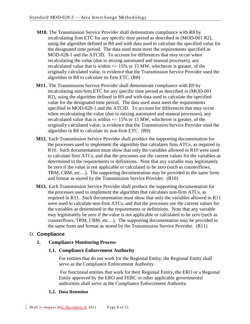
Standard MOD-028-2 — Area In te rchange Methodology
Draft 1: Augus t 302: December 9, 2011 Page 8 o f 15
M10. The Transmission Service Provider shall demonstrate compliance with R8 by recalculating firm ETC
M11. The Transmission Service Provider shall demonstrate compliance with R9 by recalculating non-firm ETC for any specific time period as described in (MOD-001 R2), using the algorithm defined in R9 and with data used to calculate the specified value for the designated time period. The data used must meet the requirements specified in MOD-028-1 and the ATCID. To account for differences that may occur when recalculating the value (due to mixing automated and manual processes), any recalculated value that is within +/- 15% or 15 MW, whichever is greater, of the originally calculated value, is evidence that the Transmission Service Provider used the algorithm in R8 to calculate its non-firm ETC. (R9)
for any specific time period as described in (MOD-001 R2), using the algorithm defined in R8 and with data used to calculate the specified value for the designated time period. The data used must meet the requirements specified in MOD-028-1 and the ATCID. To account for differences that may occur when recalculating the value (due to mixing automated and manual processes), any recalculated value that is within +/- 15% or 15 MW, whichever is greater, of the originally calculated value, is evidence that the Transmission Service Provider used the algorithm in R8 to calculate its firm ETC. (R8)
M12. Each Transmission Service Provider shall produce the supporting documentation for the processes used to implement the algorithm that calculates firm ATCs, as required in R10. Such documentation must show that only the variables allowed in R10 were used to calculate firm ATCs, and that the processes use the current values for the variables as determined in the requirements or definitions. Note that any variable may legitimately be zero if the value is not applicable or calculated to be zero (such as counterflows, TRM, CBM, etc…). The supporting documentation may be provided in the same form and format as stored by the Transmission Service Provider. (R10)
M13. Each Transmission Service Provider shall produce the supporting documentation for the processes used to implement the algorithm that calculates non-firm ATCs, as required in R11. Such documentation must show that only the variables allowed in R11 were used to calculate non-firm ATCs, and that the processes use the current values for the variables as determined in the requirements or definitions. Note that any variable may legitimately be zero if the value is not applicable or calculated to be zero (such as counterflows, TRM, CBM, etc…). The supporting documentation may be provided in the same form and format as stored by the Transmission Service Provider. (R11)
D. Compliance 1. Compliance Monitoring Process
1.1. Compliance Enforcement Authority For entities that do not work for the Regional Entity, the Regional Entity shall serve as the Compliance Enforcement Authority.
For functional entities that work for their Regional Entity, the ERO or a Regional Entity approved by the ERO and FERC or other applicable governmental authorities shall serve as the Compliance Enforcement Authority.
1.2. Data Retention

Standard MOD-028-2 — Area In te rchange Methodology
Draft 1: Augus t 302: December 9, 2011 Page 9 o f 15
The following evidence retention periods identify the period of time an entity is required to retain specific evidence to demonstrate compliance. For instances where the evidence retention period specified below is shorter than the time since the last audit, the Compliance Enforcement Authority may ask an entity to provide other evidence to show that it was compliant for the full time period since the last audit.
The Transmission Operator and Transmission Service Provider shall keep data or evidence to show compliance as identified below unless directed by its Compliance Enforcement Authority to retain specific evidence for a longer period of time as part of an investigation:
- The Transmission Service Provider shall retain its current, in force ATCID and any prior versions of the ATCID that were in force since the last compliance audit to show compliance with R1.
- The Transmission Operator shall have its latest model used to calculate TTC and evidence of the previous version to show compliance with R2.
- The Transmission Operator shall retain evidence to show compliance with R3 for the most recent 12 months or until the model used to calculate TTC is updated, whichever is longer.
- The Transmission Operator shall retain evidence to show compliance with R4, R5, R6 and R7 for the most recent 12 months.
- The Transmission Service Provider shall retain evidence to show compliance in calculating hourly values required in R8 and R9 for the most recent 14 days; evidence to show compliance in calculating daily values required in R8 and R9 for the most recent 30 days; and evidence to show compliance in calculating monthly values required in R8 and R9 for the most recent 60 days.
- The Transmission Service Provider shall retain evidence to show compliance with R10 and R11 for the most recent 12 months.
- If a Transmission Service Provider or Transmission Operator is found non-compliant, it shall keep information related to the non-compliance until found compliant.
- The Compliance Enforcement Authority shall keep the last audit records and all requested and submitted subsequent audit records.
1.3. Compliance Monitoring and Enforcement Processes: The following processes may be used:
- Compliance Audits
- Self-Certifications
- Spot Checking
- Compliance Violation Investigations
- Self-Reporting
- Complaints
1.4. Additional Compliance Information

Standard MOD-028-2 — Area In te rchange Methodology
Draft 1: Augus t 302: December 9, 2011 Page 10 of 15
None.

Standard MOD-028-2 — Area In te rchange Methodology
Draft 1: Augus t 302: December 9, 2011 Page 11 of 15
2. Violation Severity Levels
R # Lower VSL Moderate VSL High VSL Severe VSL
R1. The Transmission Service Provider has an ATCID but it is missing one of the following:
R1.1
R1.2
R1.3
R1.4
R1.5 (any one or more of its sub-subrequirements)
The Transmission Service Provider has an ATCID but it is missing two of the following:
R1.1
R1.2
R1.3
R1.4
R1.5 (any one or more of its sub-subrequirements)
The Transmission Service Provider has an ATCID but it is missing three of the following:
R1.1
R1.2
R1.3
R1.4
R1.5 (any one or more of its sub-subrequirements)
The Transmission Service Provider has an ATCID but it is missing more than three of the following:
R1.1
R1.2
R1.3
R1.4
R1.5 (any one or more of its sub-subrequirements)
R2. The Transmission Operator used one to ten Facility Ratings that were different from those specified by a Transmission or Generator Owner in their Transmission model.
The Transmission Operator used eleven to twenty Facility Ratings that were different from those specified by a Transmission or Generator Owner in their Transmission model.
One or both of the following:
• The Transmission Operator used twenty-one to thirty Facility Ratings that were different from those specified by a Transmission or Generator Owner in their Transmission model.
• The Transmission Operator did not use a Transmission model that includes modeling data and topology (or equivalent representation) for one adjacent Reliability Coordinator Area.
One or more of the following:
• The Transmission Operator used more than thirty Facility Ratings that were different from those specified by a Transmission or Generator Owner in their Transmission model.
• The Transmission Operator’s model includes equivalent representation of non-radial facilities greater than 161 kV for its own Reliability Coordinator Area.
• The Transmission Operator did not use a Transmission model that includes modeling data and topology (or equivalent representation) for two or more adjacent Reliability Coordinator

Standard MOD-028-2 — Area In te rchange Methodology
Draft 1: Augus t 302: December 9, 2011 Page 12 of 15
R # Lower VSL Moderate VSL High VSL Severe VSL
Areas.
R3. The Transmission Operator did not include in the TTC process one to ten expected generation and Transmission outages, additions or retirements as specified in the ATCID.
The Transmission Operator did not include in the TTC process eleven to twenty-five expected generation and Transmission outages, additions or retirements as specified in the ATCID.
The Transmission Operator did not include in the TTC process twenty-six to fifty expected generation and Transmission outages, additions or retirements as specified in the ATCID.
One or more of the following:
• The Transmission Operator did not include in the TTC process more than fifty expected generation and Transmission outages, additions or retirements as specified in the ATCID.
• The Transmission Operator did not include the Load forecast or unit commitment in its TTC calculation as described in R3.
R4.
The Transmission Operator did not model reservations’ sources or sinks as described in R4.3 for more than zero reservations, but not more than 5% of all reservations; or 1 reservation, whichever is greater.
The Transmission Operator did not model reservations’ sources or sinks as described in R4.3 for more than 5%, but not more than 10% of all reservations; or 2 reservations, whichever is greater.
The Transmission Operator did not model reservations’ sources or sinks as described in R4.3 for more than 10%, but not more than 15% of all reservations; or 3 reservations, whichever is greater.
One or more of the following:
• The Transmission Operator did not include in the TTC calculation the contingencies that met the criteria described in the ATCID.
• The Transmission Operator did not respect contractual allocations of TTC.
• The Transmission Operator did not model reservations’ sources or sinks as described in R4.3 for more than 15% of all reservations; or more than 3 reservations, whichever is greater.
• The Transmission Operator did not use firm reservations to estimate interchange or did not

Standard MOD-028-2 — Area In te rchange Methodology
Draft 1: Augus t 302: December 9, 2011 Page 13 of 15
R # Lower VSL Moderate VSL High VSL Severe VSL
utilize that estimate in the TTC calculation as described in R4.3.
R5. One or more of the following:
• The Transmission Operator did not establish TTCs for use in hourly or daily ATCs within 7 calendar days but did establish the values within 10 calendar days
• The Transmission Operator did not establish TTCs for use in monthly ATCs during a calendar month but did establish the values within the next consecutive calendar month
One or more of the following:
• The Transmission Operator did not establish TTCs for use in hourly or daily ATCs in 10 calendar days but did establish the values within 13 calendar days
• The Transmission Operator did not establish TTCs for use in monthly ATCs during a two consecutive calendar month period but did establish the values within the third consecutive calendar month
One or more of the following:
• The Transmission Operator did not establish TTCs for used in hourly or daily ATCs in 13 calendar days but did establish the values within 16 calendar days
• The Transmission Operator did not establish TTCs for use in monthly ATCs during a three consecutive calendar month period but did establish the values within the fourth consecutive calendar month
One or more of the following:
• The Transmission Operator did not establish TTCs for used in hourly or daily ATCs in 16 calendar days
• The Transmission Operator did not establish TTCs for use in monthly ATCs during a four or more consecutive calendar month period
• The Transmission Operator did not establish TTCs within 24 hrs of the triggers defined in R5.3
R6. N/A N/A N/A
The Transmission Operator did not calculate TTCs per the process specified in R6.
R7. One or more of the following:
• The Transmission Operator provided its Transmission Service Provider with its ATC Path TTCs used in hourly or daily ATC calculations more than one calendar day after their determination, but not been more than two calendar days after their determination.
• The Transmission Operator
One or more of the following:
• The Transmission Operator provided its Transmission Service Provider with its ATC Path TTCs used in hourly or daily ATC calculations more than two calendar days after their determination, but not been more than three calendar days after their determination.
• The Transmission Operator
One or more of the following:
• The Transmission Operator provided its Transmission Service Provider with its ATC Path TTCs used in hourly or daily ATC calculations more than three calendar days after their determination, but not been more than four calendar days after their determination.
• The Transmission Operator
One or more of the following:
• The Transmission Operator provided its Transmission Service Provider with its ATC Path TTCs used in hourly or daily ATC calculations more than four calendar days after their determination.
• The Transmission Operator did not provide its Transmission Service Provider with its ATC Path TTCs used in hourly or

Standard MOD-028-2 — Area In te rchange Methodology
Draft 1: Augus t 302: December 9, 2011 Page 14 of 15
R # Lower VSL Moderate VSL High VSL Severe VSL
has not provided its Transmission Service Provider with its ATC Path TTCs used in monthly ATC calculations more than seven calendar days after their determination, but not more than 14 calendar days since their determination.
has not provided its Transmission Service Provider with its ATC Path TTCs used in monthly ATC calculations more than 14 calendar days after their determination, but not been more than 21 calendar days after their determination.
has not provided its Transmission Service Provider with its ATC Path TTCs used in monthly ATC calculations more than 21 calendar days after their determination, but not been more than 28 calendar days after their determination.
daily ATC calculations.
• The Transmission Operator provided its Transmission Service Provider with its ATC Path TTCs used in monthly ATC calculations more than 28 calendar days after their determination.
• The Transmission Operator did not provide its Transmission Service Provider with its ATC Path TTCs used in monthly ATC calculations.
R8. For a specified period, the Transmission Service Provider calculated a firm ETC with an absolute value different than that calculated in M10 for the same period, and the absolute value difference was more than 15% of the value calculated in the measure or 15MW, whichever is greater, but not more than 25% of the value calculated in the measure or 25MW, whichever is greater.
For a specified period, the Transmission Service Provider calculated a firm ETC with an absolute value different than that calculated in M10 for the same period, and the absolute value difference was more than 25% of the value calculated in the measure or 25MW, whichever is greater, but not more than 35% of the value calculated in the measure or 35MW, whichever is greater.
For a specified period, the Transmission Service Provider calculated a firm ETC with an absolute value different than that calculated in M10 for the same period, and the absolute value difference was more than 35% of the value calculated in the measure or 35MW, whichever is greater, but not more than 45% of the value calculated in the measure or 45MW, whichever is greater.
For a specified period, the Transmission Service Provider calculated a firm ETC with an absolute value different than that calculated in M10 for the same period, and the absolute value difference was more than 45% of the value calculated in the measure or 45MW, whichever is greater.
R9. For a specified period, the Transmission Service Provider calculated a non-firm ETC with an absolute value different than that calculated in M11 for the same period, and the absolute value difference was more than 15% of the value calculated in the measure or 15MW, whichever is greater, but not
For a specified period, the Transmission Service Provider calculated a non-firm ETC with an absolute value different than that calculated in M11 for the same period, and the absolute value difference was more than 25% of the value calculated in the measure or 25MW, whichever is greater, but not
For a specified period, the Transmission Service Provider calculated a non-firm ETC with an absolute value different than that calculated in M11 for the same period, and the absolute value difference was more than 35% of the value calculated in the measure or 35MW, whichever is greater, but not
For a specified period, the Transmission Service Provider calculated a non-firm ETC with an absolute value different than that calculated in M11 for the same period, and the absolute value difference was more than 45% of the value calculated in the measure or 45MW, whichever is greater.

Standard MOD-028-2 — Area In te rchange Methodology
Draft 1: Augus t 302: December 9, 2011 Page 15 of 15
R # Lower VSL Moderate VSL High VSL Severe VSL
more than 25% of the value calculated in the measure or 25MW, whichever is greater.
more than 35% of the value calculated in the measure or 35MW, whichever is greater...
more than 45% of the value calculated in the measure or 45MW, whichever is greater.
R10. The Transmission Service Provider did not use all the elements defined in R10 when determining firm ATC, or used additional elements, for more than zero ATC Paths, but not more than 5% of all ATC Paths or 1 ATC Path (whichever is greater).
The Transmission Service Provider did not use all the elements defined in R10 when determining firm ATC, or used additional elements, for more than 5% of all ATC Paths or 1 ATC Path (whichever is greater), but not more than 10% of all ATC Paths or 2 ATC Paths (whichever is greater).
The Transmission Service Provider did not use all the elements defined in R10 when determining firm ATC, or used additional elements, for more than 10% of all ATC Paths or 2 ATC Paths (whichever is greater), but not more than 15% of all ATC Paths or 3 ATC Paths (whichever is greater).
The Transmission Service Provider did not use all the elements defined in R10 when determining firm ATC, or used additional elements, for more than 15% of all ATC Paths or more than 3 ATC Paths (whichever is greater).
R11. The Transmission Service Provider did not use all the elements defined in R11 when determining non-firm ATC, or used additional elements, for more than zero ATC Paths, but not more than 5% of all ATC Paths or 1 ATC Path (whichever is greater).
The Transmission Service Provider did not use all the elements defined in R11 when determining non-firm ATC, or used additional elements, for more than 5% of all ATC Paths or 1 ATC Path (whichever is greater), but not more than 10% of all ATC Paths or 2 ATC Paths (whichever is greater).
The Transmission Service Provider did not use all the elements defined in R11 when determining non-firm ATC, or used additional elements, for more than 10% of all ATC Paths or 2 ATC Paths (whichever is greater), but not more than 15% of all ATC Paths or 3 ATC Paths (whichever is greater).
The Transmission Service Provider did not use all the elements defined in R11 when determining non-firm ATC, or used additional elements, for more than 15% of all ATC Paths or more than 3 ATC Paths (whichever is greater).

Implementation Plan Project 2011-INT-01 Approvals Requested MOD-028-2 – Area Interchange Methodology Prerequisite Approvals None
Effective Date New or Revised Standards MOD-028-2—In those jurisdictions where regulatory approval is required, this standard shall become effective on the first day of the first calendar quarter after applicable regulatory approval. In those jurisdictions where no regulatory approval is required, this standard shall become effective on the first day of the first calendar quarter after Board of Trustees approval. Standards for Retirement MOD-028-1—Midnight of the day immediately prior to the Effective Date of MOD-028-2 in the particular Jurisdiction in which the new standard is becoming effective.

116-390 Village Blvd. Princeton, NJ 08540
609.452.8060 | www.nerc.com
Note: A valid interpretation request is one that requests additional clarity about one or more requirements in approved NERC reliability standards, but does not request approval as to how to comply with one or more requirements.
Request for an Interpretation of a Reliability Standard
Date submitted: 5/13/2011
Contact information for person requesting the interpretation:
Name: Don McInnis
Organization: Florida Power & Light
Telephone: 305-442-5272 E-mail: [email protected]
Identify the standard that needs clarification:
Standard Number (include version number, e.g. PRC-001-1 ): MOD-028-1
Standard Title: Area Interchange Methodology
Identify specifically what requirement needs clarification:
Requirement Number and Text of Requirement: R3.1 For on-peak and off-peak intra-day and next-day TTCs, use the following (as well as any other values and additional parameters as specified in the ATCID):
Identify the nature of clarification that is requested: (Check as many as applicable)
Clarify the required performance
Clarify the conditions under which the performance is required
Clarify which functional entity is responsible for performing an action in a requirement
Clarify the reliability outcome the requirement is intended to produce
Please explain the clarification needed:
By using the words “on-peak”, “off-peak”, and “intra-day” this requirement implies there would have to be separate TTC numbers for different portions of the current day. However, R5 of MOD28 establishes the calculation frequencies and only requires an update to TTC once within the 7 days prior to the specified period where they are used in an ATC calculation. The
When completed, email this form to: [email protected] For questions about this form or for assistance in completing the form, call Laura Hussey at 404-446-2579.

116-390 Village Blvd. Princeton, NJ 08540
609.452.8060 | www.nerc.com
clarification needed is on the ATC Drafting Team’s intent with respect to the quantity and timing of individual TTC calculations needed for use in the ATC calculations.
Identify the material impact associated with this interpretation:
Identify the material impact to your organization or others, if known, caused by the lack of clarity or an incorrect interpretation of this standard.
Adherence to the implied intra day calculation requirement of R3.1 is resulting in additional work and creating coordination issues with other parties which are not calculating intra day TTC values.
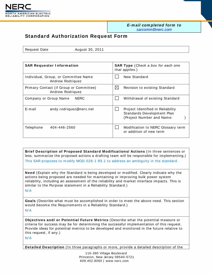
116-390 Village Boulevard Princeton, New Jersey 08540-5721 609.452.8060 | www.nerc.com
Standard Authorization Request Form
Request Date August 30, 2011
SAR Requester Information SAR Type (Check a box for each one
that applies.)
Individual, Group, or Committee Name Andrew Rodriquez
New Standard
Primary Contact (if Group or Committee) Andrew Rodriquez
Revision to existing Standard
Company or Group Name NERC Withdrawal of existing Standard
E-mail [email protected] Project Identified in Reliability Standards Development Plan (Project Number and Name: )
Telephone 404-446-2560 Modification to NERC Glossary term or addition of new term
Brief Description of Proposed Standard Modifications/Actions (In three sentences or less, summarize the proposed actions a drafting team will be responsible for implementing.)
This SAR proposes to modify MOD-028-1 R3.1 to address an ambiguity in the standard.
Need (Explain why the Standard is being developed or modified. Clearly indicate why the actions being proposed are needed for maintaining or improving bulk power system reliability, including an assessment of the reliability and market interface impacts. This is similar to the Purpose statement in a Reliability Standard.)
N/A Goals (Describe what must be accomplished in order to meet the above need. This section would become the Requirements in a Reliability Standard.) N/A
Objectives and/or Potential Future Metrics (Describe what the potential measure or criteria for success may be for determining the successful implementation of this request. Provide ideas for potential metrics to be developed and monitored in the future relative to this request, if any.)
N/A Detailed Description (In three paragraphs or more, provide a detailed description of the
E-mail completed form to [email protected]

Standards Authorization Request Form
SAR–2
proposed actions a drafting team will be responsible for executing so that the team can efficiently implement this request. While you will check applicability boxes on the following page, this description must include proportional identification of to whom the standard should apply among industry participants.) Sub-requirement R3.1 of MOD-028-1 states the following:
R3.1 For on-peak and off-peak intra-day and next-day TTCs, use the following (as well as any other values and additional parameters as specified in the ATCID):
NERC received a request to interpret this sub-requirement. The requester stated:
By using the words “on-peak”, “off-peak”, and “intra-day” this requirement implies there would have to be separate TTC numbers for different portions of the current day. However, R5 of MOD28 establishes the calculation frequencies and only requires an update to TTC once within the 7 days prior to the specified period where they are used in an ATC calculation. The clarification needed is on the ATC Drafting Team’s intent with respect to the quantity and timing of individual TTC calculations needed for use in the ATC calculations. Adherence to the implied intra day calculation requirement of R3.1 is resulting in additional work and creating coordination issues with other parties which are not calculating intra day TTC values.
While the Interpretation team was preparing its Interpretation, the Standards Committee requested the Interpretation Team use a “rapid modification” approach to clarify the requirement in question directly. The Interpretation Team is proposing the attached modification to the standard in lieu of an Interpretation. Because FERC has not yet rules on the VRFs for this standard, they have been marked as PENDING in order to not distract from the discussion of the modification. OPTIONAL: Technical Analysis Performed to Support Justification (Provide the results of any technical study or analysis performed to justify this request. Alternatively, if deemed necessary, propose a technical study or analysis that should be performed prior to a related standard development project being initiated in response to this request.) N/A
Reliability Functions
The Standard(s) May Apply to the Following Functions (Check box for each one that applies.)
Conducts the regional activities related to planning and operations, and coordinates activities of Responsible Entities to secure the reliability of the Bulk Electric System within the region and adjacent regions.
Regional Entity
Responsible for the real-time operating reliability of its Reliability Coordinator Area in coordination with its neighboring Reliability Coordinator’s wide area view.
Reliability Coordinator
Balancing Integrates resource plans ahead of time, and maintains load-
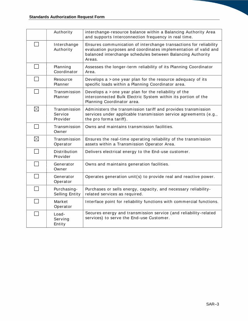
Standards Authorization Request Form
SAR–3
Authority interchange-resource balance within a Balancing Authority Area and supports Interconnection frequency in real time.
Interchange Authority
Ensures communication of interchange transactions for reliability evaluation purposes and coordinates implementation of valid and balanced interchange schedules between Balancing Authority Areas.
Planning Coordinator
Assesses the longer-term reliability of its Planning Coordinator Area.
Resource Planner
Develops a >one year plan for the resource adequacy of its specific loads within a Planning Coordinator area.
Transmission Planner
Develops a >one year plan for the reliability of the interconnected Bulk Electric System within its portion of the Planning Coordinator area.
Transmission Service Provider
Administers the transmission tariff and provides transmission services under applicable transmission service agreements (e.g., the pro forma tariff).
Transmission Owner
Owns and maintains transmission facilities.
Transmission Operator
Ensures the real-time operating reliability of the transmission assets within a Transmission Operator Area.
Distribution Provider
Delivers electrical energy to the End-use customer.
Generator Owner
Owns and maintains generation facilities.
Generator Operator
Operates generation unit(s) to provide real and reactive power.
Purchasing-Selling Entity
Purchases or sells energy, capacity, and necessary reliability-related services as required.
Market Operator
Interface point for reliability functions with commercial functions.
Secures energy and transmission service (and reliability-related services) to serve the End-use Customer.
Load-Serving Entity

Standards Authorization Request Form
SAR–4
Reliability and Market Interface Principles
Applicable Reliability Principles (Check box for all that apply.)
1.
Interconnected bulk power systems shall be planned and operated in a coordinated manner to perform reliably under normal and abnormal conditions as defined in the NERC Standards.
2.
The frequency and voltage of interconnected bulk power systems shall be controlled within defined limits through the balancing of real and reactive power supply and demand.
3.
Information necessary for the planning and operation of interconnected bulk power systems shall be made available to those entities responsible for planning and operating the systems reliably.
4.
Plans for emergency operation and system restoration of interconnected bulk power systems shall be developed, coordinated, maintained and implemented.
5.
Facilities for communication, monitoring and control shall be provided, used and maintained for the reliability of interconnected bulk power systems.
6.
Personnel responsible for planning and operating interconnected bulk power systems shall be trained, qualified, and have the responsibility and authority to implement actions.
7.
The security of the interconnected bulk power systems shall be assessed, monitored and maintained on a wide area basis.
8. Bulk power systems shall be protected from malicious physical or cyber attacks.
Does the proposed Standard(s) comply with all of the following Market Interface Principles?
1.
(Select ‘yes’ or ‘no’ from the drop-down box.)
2.
A reliability standard shall not give any market participant an unfair competitive advantage. Yes
3.
A reliability standard shall neither mandate nor prohibit any specific market structure. Yes
4.
A reliability standard shall not preclude market solutions to achieving compliance with that standard. Yes
A reliability standard shall not require the public disclosure of commercially sensitive information. All market participants shall have equal opportunity to access commercially non-sensitive information that is required for compliance with reliability standards. Yes

Standards Authorization Request Form
SAR–5
Related Standards
Standard No. Explanation
Related Projects
Project ID and Title Explanation
Regional Variances
Region Explanation
ERCOT
FRCC
MRO
NPCC
SERC
RFC
SPP
WECC
Standards Announcement Project 2011-INT-01 Revision to MOD-028-1 to Respond to FPL Request for Interpretation
Recirculation Ballot Window Open: December 12 - 22, 2011 Now Available A recirculation ballot window is now open for revisions to MOD-028-1 – Area Interchange Methodology through 8 p.m. Eastern on Thursday, December 22, 2011. In May 2011, FPL requested an interpretation of MOD-028-1, Requirement R3.1. The request asked for clarification of the timing and frequency of TTC calculations needed for ATC calculations. At its July 2011 meeting the Standards Committee approved (with FPL’s consent) addressing FPL’s request for interpretation through a rapid revision to the MOD-028-1 standard. The interpretation drafting team was appointed as the standard drafting team and directed to submit both a SAR and proposed revisions to MOD-028-1, addressing the issues raised in the request for interpretation. Because the revisions are narrowly focused on addressing the clarification requested by FPL, the Standards Committee approved waiving the initial 30-day formal comment period and directed that the SAR and proposed revisions to the standard be posted for a 45-day parallel comment period and ballot, which ended on November 16, 2011. Since the initial ballot, the drafting team has considered all comments and made no substantive changes. Only minor changes were made to correct capitalization. No changes were made to the implementation plan. Documents associated with this project, including clean and redline copies of the standard, the implementation plan (clean only since there were no changes) and the drafting team’s consideration of comments submitted during the parallel formal comment period and successive ballot that ended on November 21, 2011, have been posted on the project page. Instructions for Balloting in the Recirculation Ballot In a recirculation ballot, votes are counted by exception. Only members of the ballot pool may cast a ballot; all ballot pool members may change their prior votes. A ballot pool member who failed to cast a ballot during the last ballot window may cast a ballot in the recirculation ballot window. If a ballot pool member does not participate in the recirculation ballot, that member’s last vote cast in the initial ballot that ended on November 16, 2011 will be carried over. Members of the ballot pool associated with this project may log in and submit their votes in the recirculation ballots by clicking here: vote.

Standards Announcement: 2011-INT-01 Revision to MOD-028-1 to Respond to FPL Request for Interpretation 2
Next Steps If the standard and associated implementation plan achieve ballot pool approval, they will be presented to the Board of Trustees for adoption and subsequently filed with regulators for approval. Standards Development Process The Standard Processes Manual contains all the procedures governing the standards development process. The success of the NERC standards development process depends on stakeholder participation. We extend our thanks to all those who participate. For more information or assistance, please contact Monica Benson at [email protected].
For more information or assistance, please contact Monica Benson, Standards Process Administrator, at [email protected] or at 404-446-2560.
North American Electric Reliability Corporation 116-390 Village Blvd. Princeton, NJ 08540
609.452.8060 | www.nerc.com

Standards Announcement Project INT-2011-01 Interpretation of MOD-028-1 for FPL
Recirculation Ballot Results
Now Available
A recirculation ballot of MOD-028-2 Area Interchange Methodology and its implementation plan concluded on December 22, 2011. The standard was approved by the ballot pool. Voting statistics are listed below, and the Ballot Results webpage provides a link to the detailed initial ballot results. Initial Ballot Results Quorum: 90.10% Approval: 92.49%
Next Steps The standard and associated implementation plan will be presented to the NERC Board of Trustees for action, and if adopted, filed with regulatory authorities.
Background In May 2011, FPL requested an interpretation of MOD-028-1, Requirement R3.1. The request asked for clarification of the timing and frequency of TTC calculations needed for ATC calculations. At its July 2011 meeting the Standards Committee approved (with FPL’s consent) addressing FPL’s request for interpretation through a rapid revision to the MOD-028-1 standard. The interpretation drafting team was appointed as the standard drafting team and directed to submit both a SAR and proposed revisions to MOD-028-1, addressing the issues raised in the request for interpretation. Because the revisions are narrowly focused on addressing the clarification requested by FPL, the Standards Committee approved waiving the initial 30-day formal comment period and directed that the SAR and proposed revisions to the standard be posted for a 45-day parallel comment period and ballot, which ended on November 16, 2011. Standards Development Process The Standard Processes Manual contains all the procedures governing the standards development process. The success of the NERC standards development process depends on stakeholder participation. We extend our thanks to all those who participate. For more information or assistance, please contact Monica Benson at [email protected].

Standards Announcement: Project INT-2011-01 Ballot Results 2
For more information or assistance, please contact Monica Benson, Standards Process Administrator, at [email protected] or at 404-446-2560.
North American Electric Reliability Corporation 116-390 Village Blvd. Princeton, NJ 08540
609.452.8060 | www.nerc.com
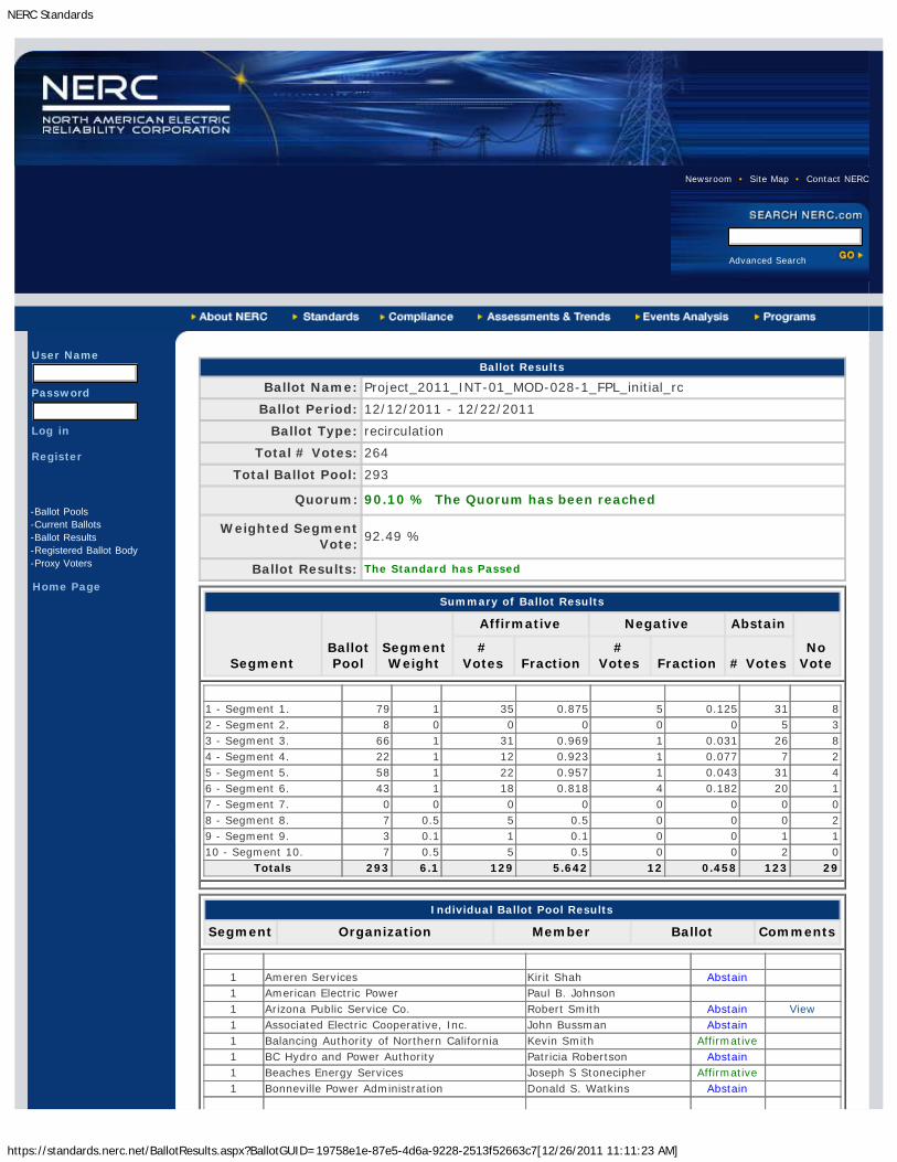
NERC Standards
https://standards.nerc.net/BallotResults.aspx?BallotGUID=19758e1e-87e5-4d6a-9228-2513f52663c7[12/26/2011 11:11:23 AM]
Newsroom • Site Map • Contact NERC
Advanced Search
User Name
Password
Log in
Register
-Ballot Pools-Current Ballots-Ballot Results-Registered Ballot Body-Proxy Voters
Home Page
Ballot Results
Ballot Name: Project_2011_INT-01_MOD-028-1_FPL_initial_rc
Ballot Period: 12/12/2011 - 12/22/2011
Ballot Type: recirculation
Total # Votes: 264
Total Ballot Pool: 293
Quorum: 90.10 % The Quorum has been reached
Weighted SegmentVote:
92.49 %
Ballot Results: The Standard has Passed
Summary of Ballot Results
SegmentBallotPool
SegmentWeight
Affirmative Negative Abstain
NoVote
#Votes Fraction
#Votes Fraction # Votes
1 - Segment 1. 79 1 35 0.875 5 0.125 31 82 - Segment 2. 8 0 0 0 0 0 5 33 - Segment 3. 66 1 31 0.969 1 0.031 26 84 - Segment 4. 22 1 12 0.923 1 0.077 7 25 - Segment 5. 58 1 22 0.957 1 0.043 31 46 - Segment 6. 43 1 18 0.818 4 0.182 20 17 - Segment 7. 0 0 0 0 0 0 0 08 - Segment 8. 7 0.5 5 0.5 0 0 0 29 - Segment 9. 3 0.1 1 0.1 0 0 1 110 - Segment 10. 7 0.5 5 0.5 0 0 2 0
Totals 293 6.1 129 5.642 12 0.458 123 29
Individual Ballot Pool Results
Segment Organization Member Ballot Comments
1 Ameren Services Kirit Shah Abstain1 American Electric Power Paul B. Johnson1 Arizona Public Service Co. Robert Smith Abstain View1 Associated Electric Cooperative, Inc. John Bussman Abstain1 Balancing Authority of Northern California Kevin Smith Affirmative1 BC Hydro and Power Authority Patricia Robertson Abstain1 Beaches Energy Services Joseph S Stonecipher Affirmative1 Bonneville Power Administration Donald S. Watkins Abstain
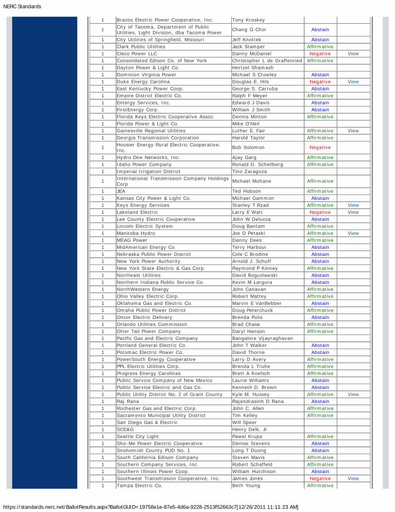
NERC Standards
https://standards.nerc.net/BallotResults.aspx?BallotGUID=19758e1e-87e5-4d6a-9228-2513f52663c7[12/26/2011 11:11:23 AM]
1 Brazos Electric Power Cooperative, Inc. Tony Kroskey
1 City of Tacoma, Department of PublicUtilities, Light Division, dba Tacoma Power
Chang G Choi Abstain
1 City Utilities of Springfield, Missouri Jeff Knottek Abstain1 Clark Public Utilities Jack Stamper Affirmative1 Cleco Power LLC Danny McDaniel Negative View1 Consolidated Edison Co. of New York Christopher L de Graffenried Affirmative1 Dayton Power & Light Co. Hertzel Shamash1 Dominion Virginia Power Michael S Crowley Abstain1 Duke Energy Carolina Douglas E. Hils Negative View1 East Kentucky Power Coop. George S. Carruba Abstain1 Empire District Electric Co. Ralph F Meyer Affirmative1 Entergy Services, Inc. Edward J Davis Abstain1 FirstEnergy Corp. William J Smith Abstain1 Florida Keys Electric Cooperative Assoc. Dennis Minton Affirmative1 Florida Power & Light Co. Mike O'Neil1 Gainesville Regional Utilities Luther E. Fair Affirmative View1 Georgia Transmission Corporation Harold Taylor Affirmative
1 Hoosier Energy Rural Electric Cooperative,Inc.
Bob Solomon Negative
1 Hydro One Networks, Inc. Ajay Garg Affirmative1 Idaho Power Company Ronald D. Schellberg Affirmative1 Imperial Irrigation District Tino Zaragoza
1 International Transmission Company HoldingsCorp
Michael Moltane Affirmative
1 JEA Ted Hobson Affirmative1 Kansas City Power & Light Co. Michael Gammon Abstain1 Keys Energy Services Stanley T Rzad Affirmative View1 Lakeland Electric Larry E Watt Negative View1 Lee County Electric Cooperative John W Delucca Abstain1 Lincoln Electric System Doug Bantam Affirmative1 Manitoba Hydro Joe D Petaski Affirmative View1 MEAG Power Danny Dees Affirmative1 MidAmerican Energy Co. Terry Harbour Abstain1 Nebraska Public Power District Cole C Brodine Abstain1 New York Power Authority Arnold J. Schuff Abstain1 New York State Electric & Gas Corp. Raymond P Kinney Affirmative1 Northeast Utilities David Boguslawski Abstain1 Northern Indiana Public Service Co. Kevin M Largura Abstain1 NorthWestern Energy John Canavan Affirmative1 Ohio Valley Electric Corp. Robert Mattey Affirmative1 Oklahoma Gas and Electric Co. Marvin E VanBebber Abstain1 Omaha Public Power District Doug Peterchuck Affirmative1 Oncor Electric Delivery Brenda Pulis Abstain1 Orlando Utilities Commission Brad Chase Affirmative1 Otter Tail Power Company Daryl Hanson Affirmative1 Pacific Gas and Electric Company Bangalore Vijayraghavan1 Portland General Electric Co. John T Walker Abstain1 Potomac Electric Power Co. David Thorne Abstain1 PowerSouth Energy Cooperative Larry D Avery Affirmative1 PPL Electric Utilities Corp. Brenda L Truhe Affirmative1 Progress Energy Carolinas Brett A Koelsch Affirmative1 Public Service Company of New Mexico Laurie Williams Abstain1 Public Service Electric and Gas Co. Kenneth D. Brown Abstain1 Public Utility District No. 2 of Grant County Kyle M. Hussey Affirmative View1 Raj Rana Rajendrasinh D Rana Abstain1 Rochester Gas and Electric Corp. John C. Allen Affirmative1 Sacramento Municipal Utility District Tim Kelley Affirmative1 San Diego Gas & Electric Will Speer1 SCE&G Henry Delk, Jr.1 Seattle City Light Pawel Krupa Affirmative1 Sho-Me Power Electric Cooperative Denise Stevens Abstain1 Snohomish County PUD No. 1 Long T Duong Abstain1 South California Edison Company Steven Mavis Affirmative1 Southern Company Services, Inc. Robert Schaffeld Affirmative1 Southern Illinois Power Coop. William Hutchison Abstain1 Southwest Transmission Cooperative, Inc. James Jones Negative View1 Tampa Electric Co. Beth Young Affirmative

NERC Standards
https://standards.nerc.net/BallotResults.aspx?BallotGUID=19758e1e-87e5-4d6a-9228-2513f52663c7[12/26/2011 11:11:23 AM]
1 Tennessee Valley Authority Larry Akens Abstain1 Tri-State G & T Association, Inc. Tracy Sliman Affirmative1 Tucson Electric Power Co. John Tolo Abstain1 United Illuminating Co. Jonathan Appelbaum Affirmative1 Western Area Power Administration Brandy A Dunn Affirmative1 Xcel Energy, Inc. Gregory L Pieper Abstain2 Alberta Electric System Operator Mark B Thompson Abstain
2 BC Hydro VenkataramakrishnanVinnakota
Abstain
2 ISO New England, Inc. Kathleen Goodman Abstain2 Midwest ISO, Inc. Marie Knox2 New Brunswick System Operator Alden Briggs Abstain2 New York Independent System Operator Gregory Campoli2 PJM Interconnection, L.L.C. Tom Bowe Abstain2 Southwest Power Pool, Inc. Charles Yeung3 AEP Michael E Deloach Abstain3 Alabama Power Company Richard J. Mandes Affirmative3 Ameren Services Mark Peters Abstain3 Anaheim Public Utilities Dept. Kelly Nguyen Abstain3 APS Steven Norris Abstain3 Atlantic City Electric Company NICOLE BUCKMAN Abstain3 BC Hydro and Power Authority Pat G. Harrington Abstain3 Black Hills Power Andy Butcher3 Bonneville Power Administration Rebecca Berdahl Abstain3 City of Bartow, Florida Matt Culverhouse3 City of Clewiston Lynne Mila Affirmative3 City of Green Cove Springs Gregg R Griffin3 City of Redding Bill Hughes Affirmative3 Cleco Corporation Michelle A Corley Negative View3 Consolidated Edison Co. of New York Peter T Yost Affirmative3 Consumers Energy Richard Blumenstock Abstain3 Delmarva Power & Light Co. Michael R. Mayer Abstain3 Detroit Edison Company Kent Kujala Affirmative3 Dominion Resources Services Michael F. Gildea Affirmative3 Duke Energy Carolina Henry Ernst-Jr Affirmative3 Entergy Joel T Plessinger Abstain3 FirstEnergy Energy Delivery Stephan Kern Abstain3 Florida Municipal Power Agency Joe McKinney Affirmative View3 Florida Power Corporation Lee Schuster Affirmative3 Georgia Power Company Anthony L Wilson Affirmative3 Georgia Systems Operations Corporation William N. Phinney Affirmative3 Grays Harbor PUD Wesley W Gray Affirmative3 Gulf Power Company Paul C Caldwell Affirmative3 Harney Electric Cooperative, Inc. Shane Sweet Abstain3 Hydro One Networks, Inc. David Kiguel Affirmative3 JEA Garry Baker Affirmative3 Kansas City Power & Light Co. Charles Locke Abstain3 Kissimmee Utility Authority Gregory D Woessner3 Lincoln Electric System Jason Fortik Affirmative3 Louisville Gas and Electric Co. Charles A. Freibert Affirmative3 Manitoba Hydro Greg C. Parent Affirmative View3 Manitowoc Public Utilities Thomas E Reed Abstain3 Mississippi Power Jeff Franklin Affirmative3 Municipal Electric Authority of Georgia Steven M. Jackson Affirmative3 Nebraska Public Power District Tony Eddleman Abstain3 New York Power Authority Marilyn Brown Abstain3 Niagara Mohawk (National Grid Company) Michael Schiavone Affirmative3 Northern Indiana Public Service Co. William SeDoris Abstain3 Ocala Electric Utility David Anderson Affirmative3 Oregon Trail Electric Cooperative ned ratterman Affirmative3 Orlando Utilities Commission Ballard K Mutters Abstain3 Owensboro Municipal Utilities Thomas T Lyons Affirmative3 Pacific Gas and Electric Company John H Hagen Affirmative View3 PacifiCorp Dan Zollner Abstain3 Platte River Power Authority Terry L Baker Affirmative3 Potomac Electric Power Co. Robert Reuter3 Progress Energy Carolinas Sam Waters Affirmative

NERC Standards
https://standards.nerc.net/BallotResults.aspx?BallotGUID=19758e1e-87e5-4d6a-9228-2513f52663c7[12/26/2011 11:11:23 AM]
3 Public Service Electric and Gas Co. Jeffrey Mueller Abstain3 Public Utility District No. 2 of Grant County Greg Lange3 Puget Sound Energy, Inc. Erin Apperson Abstain3 Sacramento Municipal Utility District James Leigh-Kendall Affirmative3 Salt River Project John T. Underhill3 Seattle City Light Dana Wheelock Affirmative3 Seminole Electric Cooperative, Inc. James R Frauen Affirmative3 Snohomish County PUD No. 1 Mark Oens3 South Carolina Electric & Gas Co. Hubert C Young Abstain3 Tacoma Public Utilities Travis Metcalfe Abstain3 Tampa Electric Co. Ronald L Donahey Affirmative3 Tennessee Valley Authority Ian S Grant Abstain3 Tri-State G & T Association, Inc. Janelle Marriott Abstain3 Xcel Energy, Inc. Michael Ibold Abstain4 Alliant Energy Corp. Services, Inc. Kenneth Goldsmith Affirmative4 American Municipal Power Kevin Koloini Abstain4 City of Clewiston Kevin McCarthy Affirmative
4 City of New Smyrna Beach UtilitiesCommission
Tim Beyrle
4 City of Redding Nicholas Zettel Affirmative4 City Utilities of Springfield, Missouri John Allen Abstain4 Consumers Energy David Frank Ronk Affirmative4 Flathead Electric Cooperative Russ Schneider Abstain4 Florida Municipal Power Agency Frank Gaffney Affirmative View4 Fort Pierce Utilities Authority Thomas Richards4 Georgia System Operations Corporation Guy Andrews Negative View4 Madison Gas and Electric Co. Joseph DePoorter Abstain4 Northern California Power Agency Tracy R Bibb Affirmative4 Ohio Edison Company Douglas Hohlbaugh Abstain4 Old Dominion Electric Coop. Mark Ringhausen Affirmative
4 Public Utility District No. 1 of SnohomishCounty
John D Martinsen Abstain
4 Sacramento Municipal Utility District Mike Ramirez Affirmative4 Seattle City Light Hao Li Affirmative4 Seminole Electric Cooperative, Inc. Steven R Wallace Affirmative View4 South Mississippi Electric Power Association Steven McElhaney Affirmative4 Tacoma Public Utilities Keith Morisette Abstain4 Wisconsin Energy Corp. Anthony Jankowski Affirmative5 AEP Service Corp. Brock Ondayko5 Amerenue Sam Dwyer Abstain5 Arizona Public Service Co. Edward Cambridge Abstain5 Avista Corp. Edward F. Groce Abstain5 BC Hydro and Power Authority Clement Ma Abstain5 Black Hills Corp George Tatar Abstain
5 Boise-Kuna Irrigation District/dba Lucky peakpower plant project
Mike D Kukla Affirmative
5 Bonneville Power Administration Francis J. Halpin Abstain View5 City and County of San Francisco Daniel Mason Abstain5 City of Austin dba Austin Energy Jeanie Doty Abstain5 City of Redding Paul Cummings Affirmative
5 City of Tacoma, Department of PublicUtilities, Light Division, dba Tacoma Power
Max Emrick Abstain
5 City of Tallahassee Brian Horton5 Cleco Power Stephanie Huffman Negative View5 Consolidated Edison Co. of New York Wilket (Jack) Ng Affirmative5 Consumers Energy Company David C Greyerbiehl Abstain5 Detroit Edison Company Christy Wicke Affirmative5 Dominion Resources, Inc. Mike Garton Abstain5 Duke Energy Dale Q Goodwine Affirmative5 FirstEnergy Solutions Kenneth Dresner Affirmative5 Florida Municipal Power Agency David Schumann Affirmative View5 Great River Energy Preston L Walsh Abstain5 Green Country Energy Greg Froehling Abstain5 JEA John J Babik Affirmative5 Kissimmee Utility Authority Mike Blough Affirmative5 Lakeland Electric James M Howard5 Lincoln Electric System Dennis Florom Affirmative5 Los Angeles Department of Water & Power Kenneth Silver
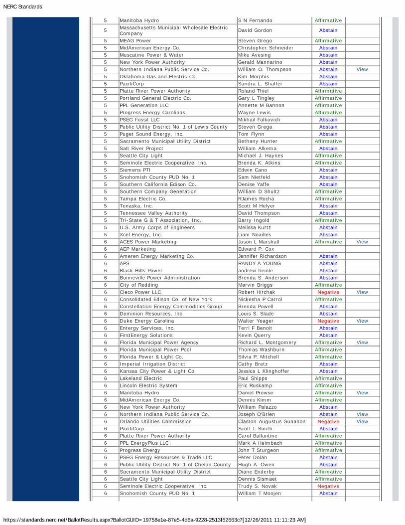
NERC Standards
https://standards.nerc.net/BallotResults.aspx?BallotGUID=19758e1e-87e5-4d6a-9228-2513f52663c7[12/26/2011 11:11:23 AM]
5 Manitoba Hydro S N Fernando Affirmative
5 Massachusetts Municipal Wholesale ElectricCompany
David Gordon Abstain
5 MEAG Power Steven Grego Affirmative5 MidAmerican Energy Co. Christopher Schneider Abstain5 Muscatine Power & Water Mike Avesing Abstain5 New York Power Authority Gerald Mannarino Abstain5 Northern Indiana Public Service Co. William O. Thompson Abstain View5 Oklahoma Gas and Electric Co. Kim Morphis Abstain5 PacifiCorp Sandra L. Shaffer Abstain5 Platte River Power Authority Roland Thiel Affirmative5 Portland General Electric Co. Gary L Tingley Affirmative5 PPL Generation LLC Annette M Bannon Affirmative5 Progress Energy Carolinas Wayne Lewis Affirmative5 PSEG Fossil LLC Mikhail Falkovich Abstain5 Public Utility District No. 1 of Lewis County Steven Grega Abstain5 Puget Sound Energy, Inc. Tom Flynn Abstain5 Sacramento Municipal Utility District Bethany Hunter Affirmative5 Salt River Project William Alkema Abstain5 Seattle City Light Michael J. Haynes Affirmative5 Seminole Electric Cooperative, Inc. Brenda K. Atkins Affirmative5 Siemens PTI Edwin Cano Abstain5 Snohomish County PUD No. 1 Sam Nietfeld Abstain5 Southern California Edison Co. Denise Yaffe Abstain5 Southern Company Generation William D Shultz Affirmative5 Tampa Electric Co. RJames Rocha Affirmative5 Tenaska, Inc. Scott M Helyer Abstain5 Tennessee Valley Authority David Thompson Abstain5 Tri-State G & T Association, Inc. Barry Ingold Affirmative5 U.S. Army Corps of Engineers Melissa Kurtz Abstain5 Xcel Energy, Inc. Liam Noailles Abstain6 ACES Power Marketing Jason L Marshall Affirmative View6 AEP Marketing Edward P. Cox6 Ameren Energy Marketing Co. Jennifer Richardson Abstain6 APS RANDY A YOUNG Abstain6 Black Hills Power andrew heinle Abstain6 Bonneville Power Administration Brenda S. Anderson Abstain6 City of Redding Marvin Briggs Affirmative6 Cleco Power LLC Robert Hirchak Negative View6 Consolidated Edison Co. of New York Nickesha P Carrol Affirmative6 Constellation Energy Commodities Group Brenda Powell Abstain6 Dominion Resources, Inc. Louis S. Slade Abstain6 Duke Energy Carolina Walter Yeager Negative View6 Entergy Services, Inc. Terri F Benoit Abstain6 FirstEnergy Solutions Kevin Querry Abstain6 Florida Municipal Power Agency Richard L. Montgomery Affirmative View6 Florida Municipal Power Pool Thomas Washburn Affirmative6 Florida Power & Light Co. Silvia P. Mitchell Affirmative6 Imperial Irrigation District Cathy Bretz Abstain6 Kansas City Power & Light Co. Jessica L Klinghoffer Abstain6 Lakeland Electric Paul Shipps Affirmative6 Lincoln Electric System Eric Ruskamp Affirmative6 Manitoba Hydro Daniel Prowse Affirmative View6 MidAmerican Energy Co. Dennis Kimm Affirmative6 New York Power Authority William Palazzo Abstain6 Northern Indiana Public Service Co. Joseph O'Brien Abstain View6 Orlando Utilities Commission Claston Augustus Sunanon Negative View6 PacifiCorp Scott L Smith Abstain6 Platte River Power Authority Carol Ballantine Affirmative6 PPL EnergyPlus LLC Mark A Heimbach Affirmative6 Progress Energy John T Sturgeon Affirmative6 PSEG Energy Resources & Trade LLC Peter Dolan Abstain6 Public Utility District No. 1 of Chelan County Hugh A. Owen Abstain6 Sacramento Municipal Utility District Diane Enderby Affirmative6 Seattle City Light Dennis Sismaet Affirmative6 Seminole Electric Cooperative, Inc. Trudy S. Novak Negative6 Snohomish County PUD No. 1 William T Moojen Abstain
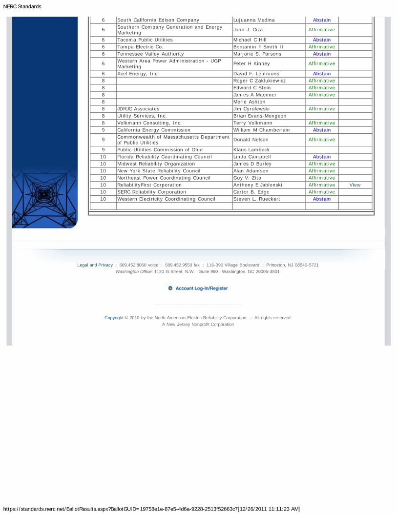
NERC Standards
https://standards.nerc.net/BallotResults.aspx?BallotGUID=19758e1e-87e5-4d6a-9228-2513f52663c7[12/26/2011 11:11:23 AM]
6 South California Edison Company Lujuanna Medina Abstain
6 Southern Company Generation and EnergyMarketing
John J. Ciza Affirmative
6 Tacoma Public Utilities Michael C Hill Abstain6 Tampa Electric Co. Benjamin F Smith II Affirmative6 Tennessee Valley Authority Marjorie S. Parsons Abstain
6 Western Area Power Administration - UGPMarketing
Peter H Kinney Affirmative
6 Xcel Energy, Inc. David F. Lemmons Abstain8 Roger C Zaklukiewicz Affirmative8 Edward C Stein Affirmative8 James A Maenner Affirmative8 Merle Ashton8 JDRJC Associates Jim Cyrulewski Affirmative8 Utility Services, Inc. Brian Evans-Mongeon8 Volkmann Consulting, Inc. Terry Volkmann Affirmative9 California Energy Commission William M Chamberlain Abstain
9 Commonwealth of Massachusetts Departmentof Public Utilities
Donald Nelson Affirmative
9 Public Utilities Commission of Ohio Klaus Lambeck10 Florida Reliability Coordinating Council Linda Campbell Abstain10 Midwest Reliability Organization James D Burley Affirmative10 New York State Reliability Council Alan Adamson Affirmative10 Northeast Power Coordinating Council Guy V. Zito Affirmative10 ReliabilityFirst Corporation Anthony E Jablonski Affirmative View10 SERC Reliability Corporation Carter B. Edge Affirmative10 Western Electricity Coordinating Council Steven L. Rueckert Abstain
Legal and Privacy : 609.452.8060 voice : 609.452.9550 fax : 116-390 Village Boulevard : Princeton, NJ 08540-5721Washington Office: 1120 G Street, N.W. : Suite 990 : Washington, DC 20005-3801
Copyright © 2010 by the North American Electric Reliability Corporation. : All rights reserved.A New Jersey Nonprofit Corporation

Exhibit F
Standard Drafting Team Roster for NERC Standards Development Project INT-2011-01

Project 2011-INT-01 (MOD-028-1) Drafting Team Roster
Name and Title Company and Address Contact Info Bio
Laura Lee, Reliability Standards Development Manager
Duke Energy 526 South Church Street, Charlotte NC 28202
[email protected] (704) 382-3625
Laura Lee is the Reliability Standards Development Manager at Duke Energy. With over 23 years of experience in the bulk power industry, Lee has worked in Design Engineering and Systems Engineering at the Catawba Nuclear Station; served as a Reliability Coordinator for the VACAR South region; performed transmission studies for evaluating reliability of the bulk transmission network, available transfer capability and transmission and generation outage coordination; chaired the NERC standard drafting team that developed the ATC standards (including MOD-028); and managed the development and implementation of a non-firm parallel flow management process between Duke Energy and Progress Energy. Lee has a Bachelor of Science in Electrical Engineering and a Master of Science in Electrical Engineering, specializing in Power Systems – both from Clemson University. Lee is a registered professional engineer in the states of North Carolina and South Carolina, and is also a NERC-certified Reliability Coordinator.

D. Dushaune Carter, Operations Planning Engineer
Southern Company 600 North 18th St PCC Corp-Hq Birmingham, AL 35291
[email protected] (205) 257-3657
D. Dushaune Carter is an Operations Planning Engineer with Southern Company Services in Birmingham, Alabama. One of his primary roles has been performing integrated planning and coordination studies for reliable operation of the bulk power system within the "next day" to 13 month timeframe. He also has had experience in the facilitation of transmission markets; the calculation of Total Transfer Capability and Available Transfer Capability values; and coordination of transmission interfaces, generation outages, transmission outages, operating agreements, and transmission service requests. Carter also has developed coordinated interconnection studies and evaluated system impacts to determine the effects of new generation additions, and worked with other utilities within SERC to create regional system base case models and perform long term reliability studies. Carter is the chair of the SERC ATC working group that developed Region Criteria for the NERC MOD standards, including MOD-028. He has a Bachelor of Science in Electrical Engineering and a Master of Science in Electrical Engineering, specializing in Power Systems – both from Mississippi State University. Carter is a registered professional engineer in the state of Alabama.
Dennis Kimm, Senior Transmission Engineer
MidAmerican Energy Co. 4299 NW Urbandale Drive, Urbandale IA 50322
[email protected] (515) 252-6737
Dennis Kimm is an Energy Trader at MidAmerican Energy, offering customer perspectives with regard to the purchasing and scheduling of transmission service within the Mid-Atlantic Power Pool, the Midwest ISO, and the PJM Interconnection. Prior to his 12 years as an Energy Trader, Kimm served as a senior transmission engineer at the Mid-America Interconnected Network (MAIN) region, performing studies to calculate Available Transfer Capability for the region. Kimm has a Bachelor of Science in Electrical Engineering with a specialization in Power Systems from Iowa State University.

Cheryl Mendrala, Principal Engineer
ISO New England, Inc. One Sullivan Road, Holyoke, MA 01040
[email protected] (413) 535-4184
Cheryl Mendrala is a Principal Engineer in System Operations Support group at ISO New England. With 12 years at the ISO, she has been involved with External Transactions at ISO New England since the design-phase of the current ISO markets. Her duties in this area include represent System Operations (primarily focused on External Transactions) to other departments inside the ISO, supporting the control room applications that relate to External Transactions, and supporting ISO customer service in addressing questions related to External Transactions. Mendrala has also been involved with Markets Development in evaluating possible market designs to improve seams issues between ISO New England and their neighboring areas. As a member of the NERC Interchange Distribution Calculator Working Group and the NERC Interchange Subcommittee, Mendrala has had significant experience dealing with the scheduling and curtailment of transmission service. Mendrala also served as a member of the NPCC CO-13 ATC Working Group, ensuring appropriate coordination between the NPCC areas as the ATC standards were implemented.

Nathan Schweighart
Tennessee Valley Authority 1101 Market Street PCC 2A Chattanooga, TN 37402
[email protected] (423) 697-4189
Nathan Schweighart has worked at Tennessee Valley Authority (TVA) for over 11 years. Schweighart has worked in various roles at TVA, with most of his professional focus in the areas of Transmission Operations and Transmission Planning. Schweighart has managed the transfer capability calculation process for TVA for the last three years and is currently the manager of the Transmission and Interchange Services group. In the past, Schweighart has helped develop TVA’s Transmission Service Request study process and Transmission Reliability Margin methodology, and participated in the VACAR Southern TVA Entergy (VSTE) and VACAR AEP Southern TVA Entergy (VASTE) Study Groups, including the creation of the VSTE PSS/E base cases. Schweighart has a Bachelor of Science in Electrical Engineering with a specialization in Power Engineering from the University of Illinois at Champaign-Urbana, as well as a Masters in Business Administration from the University of Tennessee in Chattanooga.