film cooling effectiveness from a single scaled...
TRANSCRIPT

1
Proceedings of ASME Turbo Expo 2005Power for Land, Sea, and Air
June 6–9, 2005, Reno-Tahoe, Nevada, USA
GT2005-68431
FILM COOLING EFFECTIVENESS FROM A SINGLE SCALED-UP FAN-SHAPED HOLEA CFD SIMULATION OF ADIABATIC AND CONJUGATE HEAT TRANSFER MODELS
Mahmood Silieti , Alain J. Kassab , and Eduardo Divo‡ ‡ ‡‡
‡ Mechanical, Materials, and Aerospace Engineering Department‡‡ Department of Engineering Technology
University of Central FloridaOrlando, Florida 32816-2450
Abstract This paper documents a computational investigation of thefilm cooling effectiveness of a 3-D gas turbine endwall with onefan-shaped cooling hole. The simulations were performed foradiabatic and conjugate heat transfer models. Turbulence closurewas investigated using three different turbulence models; therealizable - model, the SST - model, as well as the 5 5 @ 0% = #
turbulence model. Results were obtained for a blowing ratio ofone, and a coolant-to-mainflow temperature ratio of 0.54. Thesimulations used a dense, high quality, O-type, hexahedral gridwith three different schemes of meshing for the cooling hole:hexahedral-, hybrid-, and tetrahedral-topology grid. Thecomputed flow/temperature fields are presented, in addition tolocal, two-dimensional distribution of film cooling effectivenessfor the adiabatic and conjugate cases. Results are compared toexperimental data in terms of centerline film coolingeffectiveness downstream cooling-hole, the predictions withrealizable - turbulence model exhibited the best agreement5 %especially in the region for 2 . Also, tÐ Ÿ BÎH Ÿ 'Ñ he resultsshow the effect of the conjugate heat transfer on the temperature(effectiveness) field in the film cooling hole region and, thus, theadditional heating up of the cooling jet itself.
Nomenclature BEM Boundary Element Method CFD Computational Fluid Dynamics CHT Conjugate Heat Transfer specific heat at constant pressureG:
film cooling hole diameterH
DNS Direct Numerical Simulation an elliptic relaxation function 0
FEM Finite Element Method
I momentum ratio, I=Ð Z Ñ ÎÐ Z Ñ3 3-# #
7+38
turbulent kinetic energy5
film-cooling hole lengthP
LES Large Eddy Simulation Q blowing ratio, Q œ Ð Z Ñ ÎÐ Z Ñ3 3- 7+38
T< Prandtl number = /V/- Reynolds number defined as, V/ Z Hc 3 .- - -
RKE the realizable 5- turbulence model%
RSM Reynolds Stress Model SST the shear stress transport - turbulence model5 =
temperature magnitudeX
velocity magnitudeZ
V2F the @ 0# turbulence model @#
— velocity variance scale
streamwise distance measured from hole centerlineB
vertical distance measured from top of the holeC
z spanwise distance measured from hole centerline law of the wall coordinateC
injection/inclination angleα
turbulent dissipation rate%
or local film cooling effectiveness( Eta density3
specific dissipation rate=
Subscripts adiabaticE[
coolant-
conjugateG984
mainflow7
recovery<
total>
free stream∞

2
Introduction and Literature Review Land-based industrial gas turbines are commonly operatedcontinuously over long operational hours. This places severedemands on component life and overall performance for suchengines. Increasing performance and efficiency are somewhatconflicting goals as high efficiency requires increasinglyelevated turbine inlet temperatures, while increasing turbineinlet temperature reduces component life. Consequently,cooling of gas turbine components is required, and film cooling[1] is widely used as an effective means to maintain componenttemperatures at acceptable levels. The efficacy of such a coolingscheme can be expressed in terms of cooling effectiveness,which is closely related to the velocity and temperature profilesas well as velocity and thermal boundary layer thickness. It is well known that significant improvement can beachieved in cooling characteristics of the film by using coolingholes with appropriately designed expanded exits. Goldstein etal. [2] were among the first to pioneer the use of shaped filmholes for improved film cooling performance. The performanceof inclined holes with 10° laterally flared exit was comparedwith the performance of streamwise inclined cylindrical filmholes. Effectiveness data showed that the shaped film holeprovides better lateral coverage and better centerlineeffectiveness. Makki and Jakubowski [3] presented downstreamheat transfer results for a film hole with a trapezoidal shapedexpansion. They showed that the shaped film hole consistentlyprovided better heat transfer characteristics than simplecylindrical holes with the same metering section. Also, Makkiand Jakubowski reported that the shaped holes offered up to 23percent better film cooling performance than the correspondingcylindrical hole. Schmidt et al [4] and Sen et al. [5] presented two companionpapers in which the effect of adding a 15° forward diffusion exitto a streamwise oriented hole was investigated. They found thatthe exit diffused film hole demonstrated better spread ofadiabatic effectiveness than the cylindrical counterpart. From theheat transfer coefficient standpoint, the forward expanded holeperformed poorly, presumably because of the increasedinteraction between the jet and mainstream. Hyams et al. [6]studied the effects of slot jet shaping on the heat transferdownstream of a slot jet. They found that shaping of the slotinlet and exit provided significant gains in the film coolingperformance. Also, Hyams and Leylek [7] examined the filmcooling process for a shaped, streamwise injected, inclined jetfor a blowing ratio of 1.25 and 1.88. Detailed field results aswell as surface phenomena involving adiabatic filmeffectiveness and heat transfer coefficient are presented. Theyfound that the laterally diffused, simple angle holes provided thebest coverage and highest surface effectiveness magnitudes. Wittig et al. [8], Thole et al. [9] and Gritsch et al. [10]studied the effect of film hole geometry on the film coolingflowfield. They provided measurements for the flowfield and thefilm cooling effectiveness downstream of a cylindrical, a
laterally expanded, and a laterally forward expanded film-cooling hole. In these papers, the crossflow Mach number at thehole entrance side was taken up to 0.6, the crossflow Machnumber at the hole exit side was taken up to 1.2, the blowingratio taken up to 2, while the coolant-to-mainflow temperatureratio is kept constant at 0.54. In a companion paper, Giebert etal. [11] presented comparison of numerical calculations withflowfield measurements for the same hole geometries. Goodresults were achieved for the hole with forward-laterallyexpanded exit for the adiabatic film cooling effectiveness interms of distribution of effectiveness along the jet centerline andits rate of lateral spreading. They noted that furtherimprovements of the computational results may be possible ifthe computational grid is refined and a turbulence model whichaccounts for anisotropic effects is adopted. Beger and Liburdy [12] presented distributions of velocity,streamwise vorticity, and other film cooling characteristicsdownstream of a single cylindrical hole, a single laterallydiffused hole, and a single forward diffused hole. Kohli andThole [13] numerically investigated the flowfield and in adiffused film cooling hole and its supply channel. Chen et al.[14] studied the compound-angle injection through a row ofconical holes. Bell et al. [15] measured local and spatiallyaveraged magnitudes of the adiabatic film cooling effectivenessdownstream of five different hole geometries. Yu et al. [16]experimentally studied the effects of diffusion hole-geometry onoverall film cooling performance. For gas turbine applications, as in many other heat transferapplications, it is necessary to accompany the computation of theflow and associated heat transfer in the fluid with the heatconduction inside the adjacent solid surfaces. Such as the casefor the film cooling problem under consideration in this paper.The coupling of these two modes of heat transfer is termed asconjugate heat transfer (CHT). For a typical cooled turbineairfoil/shroud at operating conditions, there are three heattransfer problems linked together: external convection, internalconvection, and conduction within the metal. The metaltemperature distribution, and temperature gradients determine toa great extent component life. However, due to the complex,coupled nature of the heat transfer problem, accurate predictionsof the metal temperature are difficult from a design standpoint.Generally, the approaches to calculate the conjugate heattransfer or the metal temperature can be divided up into twomethods: the hybrid coupling procedure method and thehomogeneous method. The hybrid method is performed usingCFD solvers coupled to a conventional FEM or BEM solver topredict the temperature distribution at the metal walls. The maindisadvantages of this method are problems associated withhandling boundaries between different calculation areas.Whereas, the homogeneous method consists of direct couplingof the fluid zone and the solid zone using the same discretizationand numerical approach. This makes it possible to have aninterpolation-free crossing of the heat fluxes between the
3
neighboring cell faces. Additionally, the wall surfacetemperature as well as the temperatures in the vane/ endwalls area direct results of this simulation. One of the recent numerical studies by Bohn et al. [17]presented the calculations of a film-cooled duct wall imposedwith adiabatic and a conjugate heat transfer condition forvarious configurations of cylindrical and shaped film-holes.They showed that the conjugate calculation method accounts forthe significant influence of heat transfer on the velocity fieldwithin the cooling film. In particular, the secondary flowvelocities are affected by local heat transfer, which variessignificantly depending on the local position. Bohn and Kusterer[18,19] have investigated the 3-D cooling jet phenomena forblade leading edge ejection from non-lateral and radiallyinclined cooling holes. Recently, Silieti et al. [20,21] investigated the numericalprediction of film cooling effectiveness in two and threedimensional gas turbine endwall/shroud for the cases ofconjugate and adiabatic heat transfer models. They consideredcooling slots, and cylindrical cooling holes at different blowingratios. They incorporated the effect of different turbulencemodels in predicting the surface temperature and hence the filmeffectiveness. In the above studies; the turbulence closure wasinvestigated using multiple turbulence models; the standard -5 %model (SKE), the RNG - model, the realizable - model5 5% %(RKE), the standard - model (SKW), the SST - model, as5 5= =well as the Reynolds Stress Model "RSM" In the two. dimensional endwall study "film cooling slots", they found thatthe - and RSM models yielded essentially the same results5 %with slight deviations, whereas, the - models underpredict the5 =flow field in comparison with the other ones and overpredict thetemperature field. For the three dimensional endwall study"cylindrical film cooling holes", they found that in the region forÐBÎH Ÿ 'Ñ, the predictions of centerline film-coolingeffectiveness by RKE model exhibited the best agreement withexperimental data, whereas, the other four models underpredicted the film-cooling effectiveness. Whereas, in the regionfor , all models over predicted the centerline film-ÐBÎH 'Ñcooling effectiveness and the best agreement was with SKEmodel and SKW model predicted the worst results. The -5 %models, especially RKE, perform better than the - models in5 =predicting the surface temperature distribution and hence, thefilm cooling effectiveness. Moreover, the results confirmed thatthe conjugate heat transfer models showed a significantdifference in the temperature predictions in comparison with theadiabatic predictions. Li and Kassab [22, 23], and Kassab etHeidmann et al. [24]al. [25] pursued a different method of coupling the fluid andsolid thermal problems. The basis for their technique is theBoundary Element Method (BEM) for the solution of solidconduction problem. Since the thermal conduction in a solid isgoverned by Laplace equation for temperature, it may be solved
only using boundary discretization. BEM takes advantage of thisfact and does not require meshing of the solid volume. This paper has three primary objectives; the first is to predictthe film cooling effectiveness for adiabatic and conjugate heattransfer models in a 3D fan-shaped cooling holes. The second isto compare the results from these predictions to experiments.The third objective is the study effect of different gridtopologies; i.e. hexahedral-, hybrid-, and tetrahedral-topologygrid on the predicted film cooling effectiveness. The presentstudy investigates the prediction of film cooling effectivenessfrom single, scaled-up fan-shaped hole geometry at an injectionangle of 30°. The flow conditions considered are a blowing ratioof one, and the coolant-to-mainflow temperature ratio of 0.54.Turbulence closure was obtained using three differentturbulence models; the realizable - model (RKE), the Shear5 %Stress Transport - model (SST) as well as turbulence5 @ 0= #
model (V2F) It also includes the velocity and temperature.fields, in addition to centerline and two-dimensional filmcooling effectiveness. Finally, The predicted centerline filmcooling effectiveness has been compared to those reported in[10]. All the simulations reported in this paper were processedusing the commercial CFD code Fluent version 6.1.22.
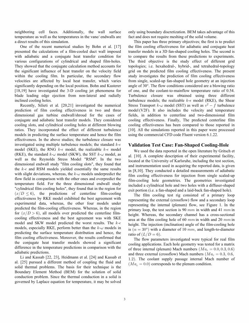
Validation Test Case: Fan-Shaped Cooling-Hole We used the data reported in the open literature by Gritsch etal. [10]. A complete description of their experimental facility,located at the University of Karlsruhe, including the test section,and instrumentation used in acquiring the reported data, is givenin [8,10]. They conducted a detailed measurements of adiabaticfilm cooling effectiveness for injection from single scaled-upfilm-cooling hole geometries. The geometries investigatedincluded a cylindrical hole and two holes with a diffuser-shapedexit portion (i.e. a fan-shaped and a laid-back fan-shaped hole). The film cooling test rig consisted of a primary looprepresenting the external (crossflow) flow and a secondary looprepresenting the internal (plenum) flow, see Figure 1. In theprimary loop, the test section is 90 in width and 41 in77 77height. Whereas, the secondary channel has a cross-sectionalarea at the film cooling hole of 60 in width and 20 in77 77height. The injection (inclination) angle of the film-cooling holeis ° with a diameter of 10 and length-to-diameterÐ œ $! Ñ 77ßαratio of .ÐPÎH œ 'Ñ The flow parameters investigated were typical for real filmcooling applications. Each hole geometry was tested for a matrixof three internal (plenum) Mach numbers ÐQ+ œ !Þ!ß !Þ$ß !Þ'Ñ-
and three external (crossflow) Mach numbers ÐQ+ œ !Þ$ß !Þ'ß-
"Þ#Ñ. The coolant supply passage internal Mach number ofÐQ+ œ !Þ!Ñ- corresponds to the plenum condition.
4
(a)
(b) Figure 1. Geometry of the experimental test case used in thisstudy: (a) overall setup; (b) fan-shaped cooling hole details.From Gritsch et al. [10].
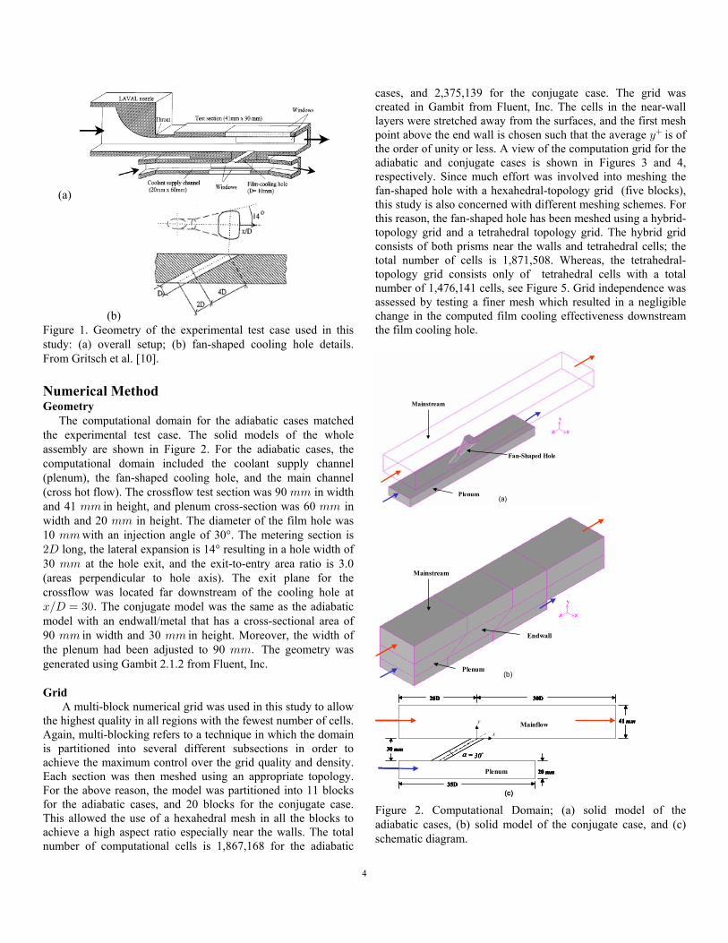
Numerical MethodGeometry The computational domain for the adiabatic cases matchedthe experimental test case. The solid models of the wholeassembly are shown in Figure 2. For the adiabatic cases, thecomputational domain included the coolant supply channel(plenum), the fan-shaped cooling hole, and the main channel(cross hot flow). The crossflow test section was 90 in width77and 41 in height, and plenum cross-section was 60 in77 77width and 20 in height. The diameter of the film hole was7710 with an injection angle of 30°. The metering section is77#H long, the lateral expansion is 14° resulting in a hole width of30 at the hole exit, and the exit-to-entry area ratio is 3.077(areas perpendicular to hole axis). The exit plane for thecrossflow was located far downstream of the cooling hole atBÎH œ $!Þ The conjugate model was the same as the adiabaticmodel with an endwall/metal that has a cross-sectional area of90 in width and 30 in height. Moreover, the width of77 77the plenum had been adjusted to 90 The geometry was77Þgenerated using Gambit 2.1.2 from Fluent, Inc.
Grid A multi-block numerical grid was used in this study to allowthe highest quality in all regions with the fewest number of cells.Again, multi-blocking refers to a technique in which the domainis partitioned into several different subsections in order toachieve the maximum control over the grid quality and density.Each section was then meshed using an appropriate topology.For the above reason, the model was partitioned into 11 blocksfor the adiabatic cases, and 20 blocks for the conjugate case.This allowed the use of a hexahedral mesh in all the blocks toachieve a high aspect ratio especially near the walls. The totalnumber of computational cells is 1,867,168 for the adiabatic
cases, and 2,375,139 for the conjugate case. The grid wascreated in Gambit from Fluent, Inc. The cells in the near-walllayers were stretched away from the surfaces, and the first meshpoint above the end wall is chosen such that the average is ofC
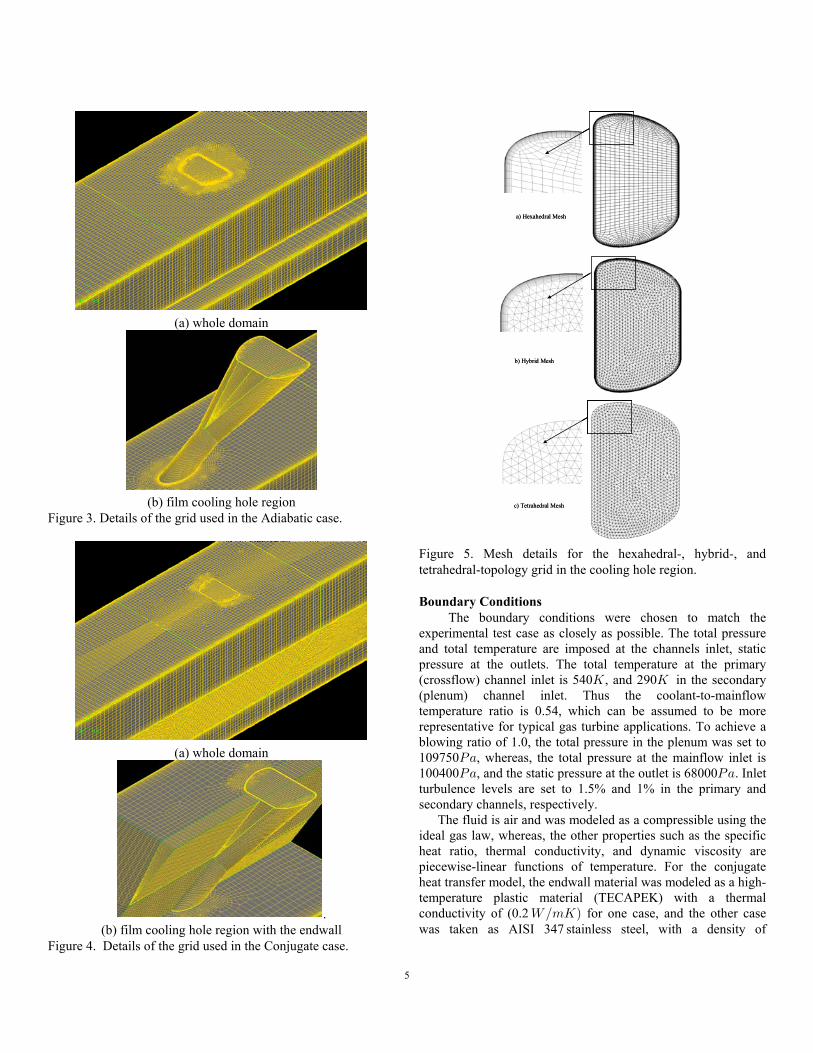
the order of unity or less. A view of the computation grid for theadiabatic and conjugate cases is shown in Figures 3 and 4,respectively. Since much effort was involved into meshing thefan-shaped hole with a hexahedral-topology grid (five blocks),this study is also concerned with different meshing schemes. Forthis reason, the fan-shaped hole has been meshed using a hybrid-topology grid and a tetrahedral topology grid. The hybrid gridconsists of both prisms near the walls and tetrahedral cells; thetotal number of cells is 1,871,508. Whereas, the tetrahedral-topology grid consists only of tetrahedral cells with a totalnumber of 1,476,141 cells, see Figure 5. Grid independence wasassessed by testing a finer mesh which resulted in a negligiblechange in the computed film cooling effectiveness downstreamthe film cooling hole.
Plenum
Mainstream
Fan-Shaped Hole
(a)Plenum
Mainstream
Fan-Shaped Hole
(a)
Mainstream
Plenum
Endwall
(b)
Mainstream
Plenum
Endwall
(b)
y
x
30D20D
35D
20 mm
41 mm
30 mmo30=α
Crossflow
Plenum
y
x
30D20D
35D
20 mm
41 mm
30 mmo30=α
Mainflow
Plenum
(c)
y
x
30D20D
35D
20 mm
41 mm
30 mmo30=α
Crossflow
Plenum
y
x
30D20D
35D
20 mm
41 mm
30 mmo30=α
Mainflow
Plenum
(c)
Figure 2. Computational Domain; (a) solid model of theadiabatic cases, (b) solid model of the conjugate case, and (c)schematic diagram.
5
(a) whole domain
(b) film cooling hole regionFigure 3. Details of the grid used in the Adiabatic case.
(a) whole domain
.(b) film cooling hole region with the endwall
Figure 4. Details of the grid used in the Conjugate case.
a) Hexahedral Mesha) Hexahedral Mesh
b) Hybrid Meshb) Hybrid Mesh
c) Tetrahedral Meshc) Tetrahedral Mesh
Figure 5. Mesh details for the hexahedral-, hybrid-, andtetrahedral-topology grid in the cooling hole region.
Boundary Conditions The boundary conditions were chosen to match theexperimental test case as closely as possible. The total pressureand total temperature are imposed at the channels inlet, staticpressure at the outlets. The total temperature at the primary(crossflow) channel inlet is 540 , and 290 in the secondaryO O(plenum) channel inlet. Thus the coolant-to-mainflowtemperature ratio is 0.54, which can be assumed to be morerepresentative for typical gas turbine applications. To achieve ablowing ratio of 1.0, the total pressure in the plenum was set to109750 , whereas, the total pressure at the mainflow inlet isT+100400 , and the static pressure at the outlet is 68000 . InletT+ T+turbulence levels are set to 1.5% and 1% in the primary andsecondary channels, respectively. The fluid is air and was modeled as a compressible using theideal gas law, whereas, the other properties such as the specificheat ratio, thermal conductivity, and dynamic viscosity arepiecewise-linear functions of temperature. For the conjugateheat transfer model, the endwall material was modeled as a high-temperature plastic material (TECAPEK) with a thermalconductivity of (0.2 for one case, and the other case[Î7OÑwas taken as AISI 347 stainless steel, with a density of

6
Ð 51Î7 Ñ7978 . The thermal conductivity is piecewise-linear$
function of temperature.
Turbulence Modeling To investigate the effect of turbulence modeling on filmcooling effectiveness predictions, turbulence closure wasimplemented using three different models: (1) the realizable -5 %model (RKE) of Shih [26] which resulted in a good agreementwith the experimental data as shown for the case of cylindricalhole, (2) the SST - model (SST) of Menter [27], and (3)5 =@ 0# model (V2F) of Durbin [28] . These models wereadopted in this study due to ease of implementation andcomputational economy, and due to the fact that they showedgood agreement in predicted film effectiveness for the 2D slotcooling and single cylindrical film-cooling holes [ ].20,21Alternative flow modeling such as DNS or models relying onsubgrid turbulence models such as LES are not considered inthis study because they are computationally very expensive andnot suitable for practical industrial computations. The impact ofeach of the three turbulence models on the prediction of filmcooling effectiveness is compared to experimental data [10] inthe results section below. Briefly, the RKE model satisfies the so-called realizabilityconstraints for the Reynolds stresses, specifically requiringpositivity of the Reynolds stresses and satisfaction of Schwarz'sinequality for the shear stresses. The RKE model has beenshown by several researchers to reduce the excessive and non-physical production of turbulent kinetic energy characteristic ofthe standard - model in areas of high irrotational strain.5 % The SST model differs from the standard - model in two5 =ways. First the gradual change from the standard - model in5 =the inner region of the boundary layer to a high-Reynoldsnumber version of the - model in the outer part of the5 %boundary layer. Second the modified turbulent viscosityformulation to account for the transport effects of the principalturbulent shear stress. Finally, the V2F model is an alternative to eddy-viscositymodels and Reynolds Stress Model. This model is similar to thestandard - model, but incorporates the near-wall turbulence5 %anisotropy and non-local pressure-strain effects. In fact, it is ageneral low Reynolds-number turbulence model that is valid allthe way up to solid walls, and therefore does not rely on wallfunctions. Although the model was originally developed forattached or mildly separated boundary layers, it also accuratelysimulates flows dominated by separation. The V2F model is afour-equation model based on transport equations for theturbulence kinetic energy ( ), its dissipation rate ( ), a velocity5 %
variance scale and an elliptic relaxation function . The—Ð@ Ñß Ð0Ñ#
distinguishing function of the model is its use of the@ 0#
velocity scale instead of the turbulent kinetic energy ( ) for—Ð@ Ñ 5#
evaluating the eddy viscosity ( ). The velocity variance scale%
Ð@ Ñ#—
which can be thought of as the velocity fluctuation normalto the streamlines, has shown to provide the right scaling inrepresenting the damping of turbulent transport close to the wall,
a feature that does not provide. Here, the model uses an5 @ 0#
elliptic operator to compute a term analogous to the pressurestrain correlation of the RSM. Ellipticity is characterized by amodified Helmholtz operator, which introduces wall effects viaa linear differential equation.
Film Cooling Effectiveness To define film cooling effectiveness, the surface temperaturedownstream of the cooling hole has to be measured. To beconsistent with the experiment [10], the definition of the localfilm cooling effectiveness was based on the mainflowÐ Ñ(recovery temperature as a reference temperature:
(ÐBÎHß DÎHÑ œXÐBÎHß DÎHÑ X
X X<ß7
>- <ß7(1)
here, is the local temperature, and it is theX ÐBÎHß DÎHÑadiabatic temperature for the adiabatic cases X ÐBÎHß DÎHÑßE[
or the conjugate temperature for the conjugate case,X ÐBÎHß DÎHÑÞ XG984 >- is the stagnation temperature of the coolant at the injection point, and is the recoveryX<ß7
temperature of the mainflow, is given by:
X œ X ÐT<Ñ Z Î#G:< ∞"Î$ #
∞(2)
In the experiment [10], the mainflow recovery temperature wasmeasured on the test plate at a location not affected by thecoolant ejection, for this reason, the recovery temperature wascalculated at a location of ÐBÎH œ &ÑÞ
Solver The simulations were processed using Fluent version 6.1.22software from Fluent, Inc. The discretization used second-orderupwinding with double precision accuracy. In the fluid zones,the steady, times-averaged Navier-Stokes equations were solved,and pressure-velocity coupling was achieved with a pressurecorrection algorithm. In the solid zone, only the Fourier equationfor heat diffusion was solved. At the fluid-solid interfaces, anenergy balance was satisfied at each iteration, such that the heatflux at the wall on the fluid side was equal in magnitude andopposite in sign to the heat flux on the solid side. Thetemperature of the boundary itself was adjusted during eachiteration to meet this condition. Convergence was determined with the following criteria: (1)reduction of all residuals of at least four orders of magnitude, (2)global mass and energy imbalances dropped below 0.001%; and(3) the flow field was unchanging and the endwall surfacetemperature did not vary with additional iterations. Under theseconditions, it was considered that a “steady state” had beenachieved.
Results This paper was primarily concerned with the computationalprediction of adiabatic and conjugate effectiveness downstreamof a 3D fan-shaped film cooling hole. Results were obtained for
7
PÎH œ 'Þ!, blowing ratio of 1.0, and coolant-to-mainflowtemperature ratio of 0.54. First, results will discuss the adiabaticmodel cases with three different turbulence models and threegrid topology schemes. Subsequently, the conjugate model casespredicted by the RKE turbulence model will be presented.
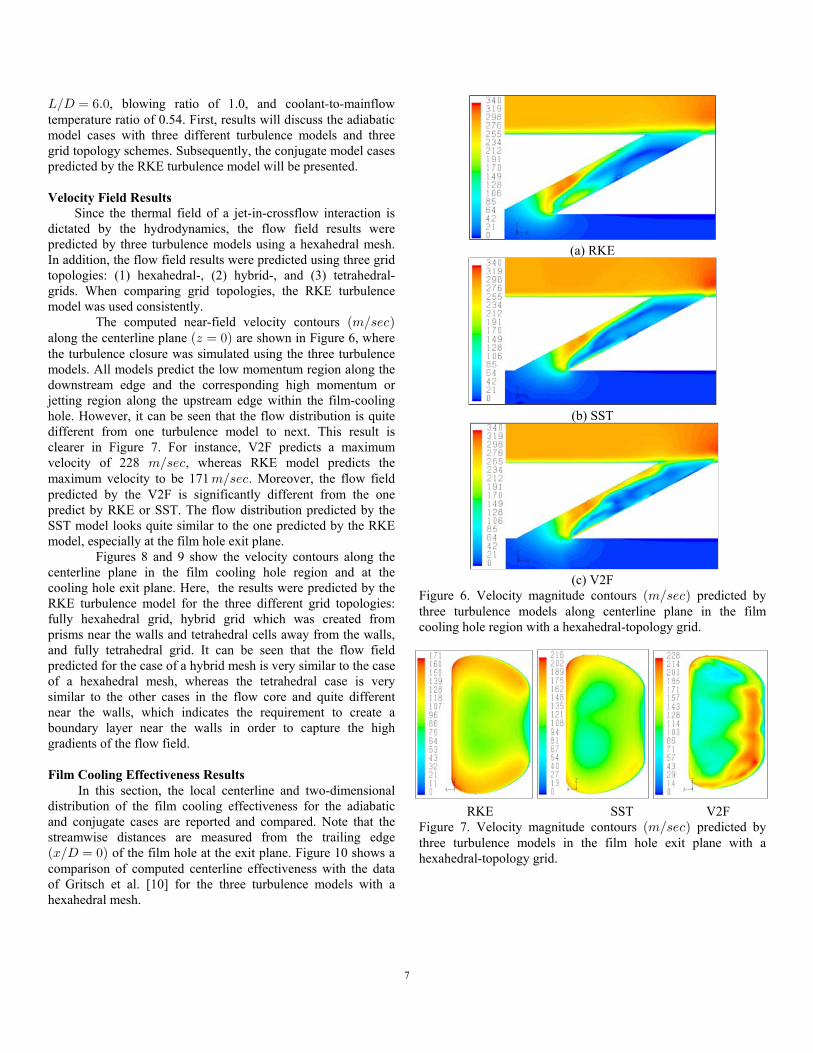
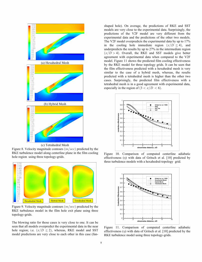
Velocity Field Results Since the thermal field of a jet-in-crossflow interaction isdictated by the hydrodynamics, the flow field results werepredicted by three turbulence models using a hexahedral mesh.In addition, the flow field results were predicted using three gridtopologies: (1) hexahedral-, (2) hybrid-, and (3) tetrahedral-grids. When comparing grid topologies, the RKE turbulencemodel was used consistently. The computed near-field velocity contours Ð7Î=/-Ñalong the centerline plane are shown in Figure 6, whereÐD œ !Ñthe turbulence closure was simulated using the three turbulencemodels. All models predict the low momentum region along thedownstream edge and the corresponding high momentum orjetting region along the upstream edge within the film-coolinghole. However, it can be seen that the flow distribution is quitedifferent from one turbulence model to next. This result isclearer in Figure 7. For instance, V2F predicts a maximumvelocity of 228 , whereas RKE model predicts the7Î=/-maximum velocity to be 171 . Moreover, the flow field7Î=/-predicted by the V2F is significantly different from the onepredict by RKE or SST. The flow distribution predicted by theSST model looks quite similar to the one predicted by the RKEmodel, especially at the film hole exit plane. Figures 8 and 9 show the velocity contours along thecenterline plane in the film cooling hole region and at thecooling hole exit plane. Here, the results were predicted by theRKE turbulence model for the three different grid topologies:fully hexahedral grid, hybrid grid which was created fromprisms near the walls and tetrahedral cells away from the walls,and fully tetrahedral grid. It can be seen that the flow fieldpredicted for the case of a hybrid mesh is very similar to the caseof a hexahedral mesh, whereas the tetrahedral case is verysimilar to the other cases in the flow core and quite differentnear the walls, which indicates the requirement to create aboundary layer near the walls in order to capture the highgradients of the flow field.
Film Cooling Effectiveness Results In this section, the local centerline and two-dimensionaldistribution of the film cooling effectiveness for the adiabaticand conjugate cases are reported and compared. Note that thestreamwise distances are measured from the trailing edgeÐBÎH œ !Ñ of the film hole at the exit plane. Figure 10 shows acomparison of computed centerline effectiveness with the dataof Gritsch et al. [10] for the three turbulence models with ahexahedral mesh.
(a) RKE
(b) SST
(c) V2F
Figure 6. Velocity magnitude contours predicted byÐ7Î=/-Ñthree turbulence models along centerline plane in the filmcooling hole region with a hexahedral-topology grid.
RKE SST V2FFigure 7. Velocity magnitude contours predicted byÐ7Î=/-Ñthree turbulence models in the film hole exit plane with ahexahedral-topology grid.
8
(a) Hexahedral Mesh
(b) Hybrid Mesh
(c) Tetrahedral MeshFigure 8. Velocity magnitude contours predicted by theÐ7Î=/-ÑRKE turbulence model along centerline plane in the film coolinghole region using three topology-grids.
Hexahedral Mesh Hybrid Mesh Tetrahedral MeshHexahedral Mesh Hybrid Mesh Tetrahedral Mesh
Figure 9. Velocity magnitude contours predicted by theÐ7Î=/-ÑRKE turbulence model in the film hole exit plane using threetopology-grids.
The blowing ratio for those cases is very close to one. It can beseen that all models overpredict the experimental data in the nearhole region; i.e. 2 , whereas, RKE model and SSTÐBÎH Ÿ Ñmodel predictions are very close to each other in this case (fan-
shaped hole). On average, the predictions of RKE and SSTmodels are very close to the experimental data. Surprisingly, thepredictions of the V2F model are very different from theexperimental data and the predictions of the other two models.The V2F model overpredicts the experimental data by up to 17%in the cooling hole immediate region 4 , andÐBÎH Ÿ Ñunderpredicts the results by up to 27% in the intermediate regionÐBÎH Ñ4 . Overall, the RKE and SST models give betteragreement with experimental data when compared to the V2Fmodel. Figure 11 shows the predicted film cooling effectivenessby the RKE model for three topology grids. It can be seen thatthe film effectiveness predicted with a hexahedral mesh is verysimilar to the case of a hybrid mesh, whereas, the resultspredicted with a tetrahedral mesh is higher than the other twocases. Surprisingly, the predicted film effectiveness with atetrahedral mesh is in a good agreement with experimental data,especially in the region of 3 6 .Ð BÎH Ñ
streamwise distance, x/D
cent
erlin
eef
fect
iven
ess
0 2 4 6 8 100
0.1
0.2
0.3
0.4
0.5
0.6
0.7
0.8
0.9
1
Gritsch et. al. 1998RKESST kwV2F
Figure 10. Comparison of computed centerline adiabaticeffectiveness ( ) with data of Gritsch et al. [10] predicted by(three turbulence models with a hexahedral-topology grid.
streamwise distance, x/D
Cen
terli
neE
ffect
iven
ess
0 2 4 6 8 100
0.1
0.2
0.3
0.4
0.5
0.6
0.7
0.8
0.9
1
Gritsch et. al. 1998Hexahedral MeshHybrid MeshTetrahedra Mesh
Figure 11. Comparison of computed centerline adiabaticeffectiveness ( ) with data of Gritsch et al. [10] predicted by the(RKE turbulence model using three topology-grids.

9
Figure 12 shows the two-dimensional distribution ofthe local film cooling effectiveness for the three adiabatic cases,as well as the conjugate case predicted by the RKE turbulencemodel. Qualitatively, all turbulence models tend to agree withthe experiment [10], whereas, the distribution of the film coolingeffectiveness for the conjugate case is significantly different.
(a) RKE
(b) SST
(c) V2F
(d) Conj.Figure 12. Local adiabatic and conjugate effectiveness ( )(predicted by three turbulence levels.
The centerline effectiveness for the adiabatic and conjugatecases compared to the experiment is shown in Figure 13. Thepredicted film effectiveness using the conjugate model is in abetter agreement with the experimental data compared to thefilm effectiveness with the adiabatic model. This finding mightbe attributed to the fact that the experimental data has someconduction effects especially for this case; i.e. fan-shaped hole.
streamwise distance, x/D
Cen
terli
neE
ffect
iven
ess
0 2 4 6 8 100
0.1
0.2
0.3
0.4
0.5
0.6
0.7
0.8
0.9
1
Gritsch et. al. 1998Adiabatic CaseConjugate Case
Figure 13. Comparison of centerline adiabatic and conjugateeffectiveness ( ) with data of Gritsch et al. [10] predicted by the(RKE turbulence model with a hexahedral-topology grid.
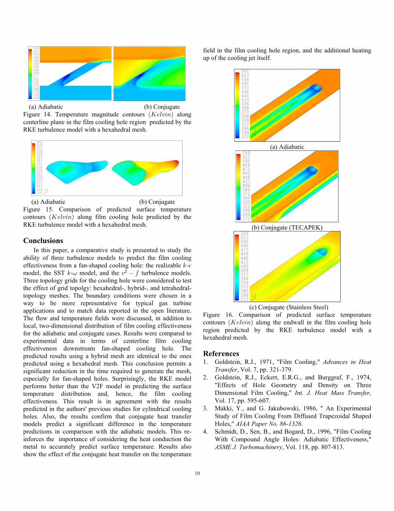
Temperature Field Results This section presents the temperature distribution in Kelvinfor the cases of adiabatic and conjugate heat transfer models.Since the RKE turbulence model gave good agreement withexperimental data as shown in the film cooling effectivenesssection, it had been used to predict the adiabatic and conjugatecases results. Figure 14 shows the computed near hole centerlinetemperature contours for the adiabatic and conjugate cases,respectively. For the conjugate case, the heat fluxes from the hotmain flow into the wall heat-up the solid body. At the filmcooling hole, an additional temperature increase of the coolingjet in comparison to the adiabatic case occurs because of the heattransfer from the hot wall into the cooling jet, see Figure 15. Anisometric view of temperature contours along the endwall andclose to the cooling hole region is presented in Figure 16 for theadiabatic and two conjugate cases, respectively. The conjugatecases were computed with very low thermal conductivityÐ!Þ#[Î7ÞOÑ. This corresponds to a high temperature plasticmaterial for the endwall (TECAPEK, the actual material used inthe experiments of Gritsch et al. [10]). The conjugate case wasmodeled using stainless steel properties for the endwall material.In the case of the fan-shaped hole, the results predicted from theadiabatic case is very similar to the results predicted byconjugate case with TECAPEK endwall material, whereas, thisis note true for the cylindrical film cooling hole. These figuresshow clearly the differences in the temperature contours for bothcases, which confirm that the conjugate heat transfer model cantake into account the mutual influences of heat transfer on thefluid flow and vice versa.
10
(a) Adiabatic (b) ConjugateFigure 14. Temperature magnitude contours alongÐO/6@38Ñcenterline plane in the film cooling hole region predicted by theRKE turbulence model with a hexahedral mesh.
(a) Adiabatic (b) ConjugateFigure 15. Comparison of predicted surface temperaturecontours along film cooling hole predicted by theÐO/6@38ÑRKE turbulence model with a hexahedral mesh.
Conclusions In this paper, a comparative study is presented to study theability of three turbulence models to predict the film coolingeffectiveness from a fan-shaped cooling hole: the realizable -5 %model, the SST - model, and the turbulence models.5 @ 0= #
Three topology grids for the cooling hole were considered to testthe effect of grid topolgy: hexahedral-, hybrid-, and tetrahedral-topology meshes. The boundary conditions were chosen in away to be more representative for typical gas turbineapplications and to match data reported in the open literature.The flow and temperature fields were discussed, in addition tolocal, two-dimensional distribution of film cooling effectivenessfor the adiabatic and conjugate cases. Results were compared toexperimental data in terms of centerline film coolingeffectiveness downstream fan-shaped cooling hole. Thepredicted results using a hybrid mesh are identical to the onespredicted using a hexahedral mesh. This conclusion permits asignificant reduction in the time required to generate the mesh,especially for fan-shaped holes. Surprisingly, the RKE modelperforms better than the V2F model in predicting the surfacetemperature distribution and, hence, the film coolingeffectiveness. This result is in agreement with the resultspredicted in the authors' previous studies for cylindrical coolingholes. Also, the results confirm that conjugate heat transfermodels predict a significant difference in the temperaturepredictions in comparison with the adiabatic models. This re-inforces the importance of considering the heat conduction themetal to accurately predict surface temperature. Results alsoshow the effect of the conjugate heat transfer on the temperature
field in the film cooling hole region, and the additional heatingup of the cooling jet itself.
(a) Adiabatic
(b) Conjugate (TECAPEK)
(c) Conjugate (Stainless Steel)Figure 16. Comparison of predicted surface temperaturecontours along the endwall in the film cooling holeÐO/6@38Ñregion predicted by the RKE turbulence model with ahexahedral mesh.
References1. Goldstein, R.J., 1971, "Film Cooling," Advances in Heat Transfer, Vol. 7, pp. 321-379.2. Goldstein, R.J., Eckert, E.R.G., and Burggraf, F., 1974, "Effects of Hole Geometry and Density on Three Dimensional Film Cooling," ,Int. J. Heat Mass Transfer Vol. 17, pp. 595-607.3. Makki, Y., and G. Jakubowski, 1986, " An Experimental Study of Film Cooling From Diffused Trapezoidal Shaped Holes," .AIAA Paper No. 86-13264. Schmidt, D., Sen, B., and Bogard, D., 1996, "Film Cooling With Compound Angle Holes: Adiabatic Effectiveness," , Vol. 118, pp. 807-813.ASME J. Turbomachinery
11
5. Sen, B., Schmidt, D., and Bogard, D., 1996, "Film Cooling With Compound Angle Holes: Heat Transfer," ASME J. Turbomachinery, Vol. 118, pp. 800-806.6. Hyams, D., McGovern, K., and Leylek, J., 1996, "Effects of Geometry on Slot-Jet Film Cooling Performance," ASME Paper No. 96-GT-187.7. Hyams, D., and Leylek, J.H., 2000, "A Detailed Analysis of Film Cooling Physics: Part III - Streamwise Injection With Shaped Holes," , Vol. 122,ASME J. Turbomachinery pp. 122-132. 8. Wittig, S., Schulz, A., Gritsch, M., and Thole, K, 1996, "Transonic Film-Cooling Investigations: Effects of Hole Shape and Orientations." ASME Paper No. 96-GT- 222.9. Thole, K.M., Gritsch, A., Schulz, and Wittg, S., 1997, "Effect of a Crossflow at the Entrance to a Film-Cooling Hole," , Vol. 119,ASME J. Fluids Engineering pp. 533-540.10. Gritsch, M., Schulz, A., and Wittig, S., 1998, "Adiabatic Wall Effectiveness Measurements of Film Cooling Holes With Expanded Exits," ASME J. Turbomachinery , Vol. 120, pp. 549-556.11. Giebert, D., Gritsch, M., Schulz, A., and Wittig, S., 1997, "Film-Cooling from Holes with Expanded Exits: A Comparison of Computational Results with Experiments", .ASME Paper No. 97-GT-16312. Berger, P.A., and Liburdy, J.A., 1998, "A Near-Field Investigation Into the Effects of Geometry and Compound Angle on the Flowfield of a Row of Film Cooling Holes," International Gas Turbine and Aeroengine Congress & Exhibition, Stockholm, .ASME Paper No. 98-GT-27913. Kohli, A., and Thole, K.A., 1998, "Entrance Effects on Diffused Film Cooling Holes," International Gas Turbine and Aeroengine Congress & Exhibition, Stockholm, ASME Paper No. 98-GT-402.14. Chen, P-H., Ai, D., and Lee, S.-H., 1998, "Effects of Compound Angle Injection on Flat-Plate Film Cooling Through a Row of Conical Holes," ASME Paper No. 99-GT-459. 15. Bell, C.M., Hamakawa, H., and Ligrani, P.M., 2000, "Film Cooling From Shaped Holes," ,ASME J. Heat Transfer Vol. 122, pp. 224-232.16. Yu, Y., Yen, C.-H., Shih, T.I.-P., Chyu, M.K., and Gogineni, S., 2002, "Film Cooling Effectiveness and Heat Transfer Coefficient Distributions Around Diffusion Shaped Holes," , Vol. 124,ASME J. Heat Transfer pp. 820-827.17. Bohn, D., Ren, J., and Kusterer, K., 2003, "Conjugate Heat Transfer Analysis for Film Cooling Configurations with Different Hole Geometries," ASME Paper No. 2003-GT - 38369, Georgia, USA.18. Bohn, D., and Kusterer, K., 1999, "Blowing Ratio Influence on Jet Mixing Flow Phenomena," AIAA Paper No. GT-2002 -30167, Amsterdam, The Netherlands.
19. Bohn, D., and Kusterer, K., 2000, "Aerothermal Investigations of Mixing Flow Phenomena in Case of Radially Inclined Ejection Holes at the Leading Edge," , Vol. 122, pp. 334-339.ASME J. Turbomachinery20. Silieti, M., Divo, E., and Kassab, A.J., 2004, "The Effect of Conjugate Heat Transfer on Film Cooling Effectiveness," , July 11-15,ASME Paper No. 2004-HT-FED-56234 Charlotte, North Carolina, USA.21. Silieti, M., Divo, E., and Kassab, A.J., 2004, "Numerical Investigation of Adiabatic and Conjugate Film Cooling Effectiveness on a Single Cylindrical Film Cooling Hole," , November 13-20,ASME Paper No. IMECE2004-62196 Anaheim, California, USA.22. Li, H. J. and Kassab, A.J., 1994, "Numerical Prediction of Fluid Flow and Heat Transfer in Turbine Blades with Internal Cooling," AIAA/ASME Paper No. 94-1981.23. Li, H. J. and Kassab, A.J., 1994, "A coupled FVM/BEM Solution to Conjugate Heat Transfer in Turbine blades," .AIAA/ASME Paper No. 94-198124. Heidmann, J.D., Kassab, A.J., Divo, E., Rodriguez, F., and Steinthorsson, E., 2003, "Conjugate Heat Transfer Effects on a Realistic Film Cooled Turbine Vane," ASME Paper No. GT2003-38369, ASME Turbo Expo 2003, June 16-19, Georgia, USA.25. Kassab, A.J., Divo, E., Heidmann, J.D., Steinthorsson, E., and Rodriguez, F., 2003, "BEM/FVM Conjugate Heat Transfer Analysis of a Three-Dimensional Film Cooled Turbine Blade," International Journal for Numerical Methods in Hea Transfer and Fluid Flow> , Vol. 13(5), pp. 581-610.26. Shih, T.-H., Liou, W.W, Shabbir, A., Yang, Z., and Zhu, J., 1995, "A New - Eddy-Viscosity Model for High5 % Reynolds Number Turbulent Flows-Model Development and Validation," , Vol. 24(3),Computers Fluids pp. 227-238.27. Menter, R., 1994, "Two-Equation Eddy-Viscosity Turbulence Models for Engineering Applications," , Vol.32(8), pp. 1598-1605.AIAA Journal28. Durbin, P.A., 1995, "Separated Flow Computations with 5 - Model," , Vol. 33(4), pp. 659-664.% @# AIAA Journal29. Parneix, S., Durbin, P.A., and Behnia, M., 1998, "Computation of a 3D Turbulent Boundary Layer Using the V2F Model," , Vol. 10,Flow Turbulence and Combustion pp. 19-46.30. Behnia, M., Parneix, S., Shabany, Y., and Behnia, M., 1999, "Numerical Study of Turbulent Heat Transfer in Confined and Unconfined Impingings Jets," International Journal of Heat and Fluid Flow, Vol. 20, pp. 1-9.