filmforming amines general aspects and application in
TRANSCRIPT

13.11.2015
1
Filmforming Amines
General aspects and application
in power plants today
Matarvattenkonferensen
Stockholm, Sweden
10. – 11. November 2015
Andre de Bache
Dr. Wolfgang Hater
• INTRODUCTION
• THE CETAMINE® TECHNOLOGY
– FILM FORMATION ON METAL SURFACES
– MAGNETITE LAYER STABILIZATION
– CETAMINE® ANALYTICAL METHOD
• CASE STUDY I
– IMPACT ON CATIONIC CONDUCTIVITY
• CASE STUDY II
– DRY LAY-UP WITH CETAMINE
• REFERENCES AND CONCLUSIONS
•13/11/2015 2
CONTENT

13.11.2015
2
BOILER WATER ADDITIVES
All-Volatile-Treatment (AVT) conceptspH adjustment realized by volatile alkalizing agents
Treatment Concept Agent 1 Agent 2
AVT-RVolatile Treatment for pH adjustment
+ Reducing agent
Ammonia
Alkalizing Amines
Hydrazin
Carbohydrazid
DEHA
AVT-O Volatile Treatment for pH adjustmentAmmonia
Alkalizing Amines
OTVolatile Treatment for pH adjustment
+ FFA (Filmforming Amines)Ammonia Oxygen
AVT-FFAVolatile Treatment for pH adjustment
+ FFA (Filmforming Amines)
Alkalizing Amines
AmmoniaFFA
Cetamine® Technology
4
BOILER WATER ADDITIVES
Alkalising
Amines
Film Forming Amines
All-in-one
product concept
to treat the
whole
water steam
cycle

13.11.2015
3
R1-NH-R2-n-NH2
R1 is an unbranched alkyl chain with 12 to 18 carbon atoms
R2 is a short-chain alkyl group with usually 1 to 4 carbon atoms
n is between 0 and 7
CETAMINE® FILMING AMINE (CFA)
• Film formation on metal surfaces
• Magnetite layer stabilization
• Improved heat transfer
• Compatibility with online sensors
• Cetamine® Photometric Method
• Wet and dry lay-up of industrial systems
• Savings in energy and water
6
BENEFITS OF CETAMINE® TECHNOLOGY

13.11.2015
4
• Adsorption and Formation of a Protective
Film on Metal Surfaces
• Hydrophobic Barrier between Water and
Metal
1 1 1
2 2
3 3
1. Adsorption
2. Ion - ion
3. Hydrophobic bond
FILM FORMATION ON METAL SURFACES
Cetamine®untreated
Protective Film
Metal
Molecules in water phase
8
FILM FORMATION ON METAL SURFACES
13.11.2015
5
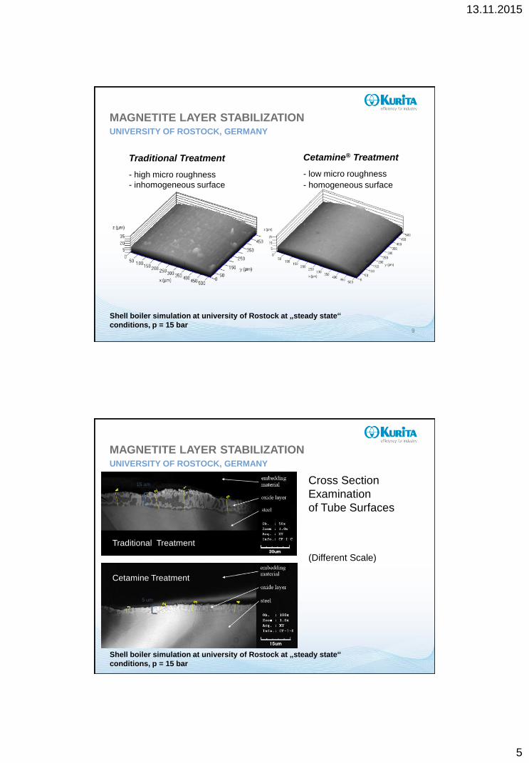
Cetamine® Treatment
- low micro roughness
- homogeneous surface
Traditional Treatment
- high micro roughness
- inhomogeneous surface
9
MAGNETITE LAYER STABILIZATIONUNIVERSITY OF ROSTOCK, GERMANY
Shell boiler simulation at university of Rostock at „steady state“
conditions, p = 15 bar
a) PO4
b) Cetamine V211
(Different Scale)
Cross Section
Examination
of Tube Surfaces
Cetamine Treatment
Traditional Treatment
15 um
5 um
MAGNETITE LAYER STABILIZATIONUNIVERSITY OF ROSTOCK, GERMANY
Shell boiler simulation at university of Rostock at „steady state“
conditions, p = 15 bar

13.11.2015
6
Iron Oxide Layer Development in 90 bars Water-Tube Boiler, Paper Industry
Acid pickling
Ammonia
PhosphateFFA Treatment
Cetamine® V211
Cetamine® V2100
Internal limit at 500 g/m²
Online cleaning
Acid pickling Acid pickling
1 According to ASTM 3483-05 Standard Test Methods for Accumulated Deposition in Steam Generator Tubes
1
MAGNETITE LAYER STABILIZATIONPAPER INDUSTRY, ISRAEL
Compatibility of Cetamine with SWAN Online-Sensors
Cetamine® FFA product 2 FFA product 3
Conductivity YES X X
pH YES YES X
Sodium YES YES YES
Oxygen YES YES YES
Full study was published by SWAN Analytical Instruments in
PowerPlant Chemistry 2012, 14(9) “Impact of Film-Forming Amines on
the Reliability of Online Analytical Instruments”
Cetamine® products are compatible with relevant online-sensors used
under these test conditions
12
COMPATIBILITY WITH ONLINE SENSORS

13.11.2015
7
Cetamine® Test Kit
Cetamine® Photometric Method
Cetamine® Monitor
13
CETAMINE® ANALYSISCUSTOMIZED SOLUTIONS
Closed hot water systems
Closed cooling systems
Industrial and district heating networks
Closed
Systems
APPROVED APPLICATIONS

13.11.2015
8
Low to High Pressure Systems
Power Plants (Turbines)
Food Industry (Direct Food Contact)
Alkaline Boiling-Out (VGB-S-513-00)
Wet and Dry Lay-Up
Steam
Generators
APPROVED APPLICATIONS
CETAMINE® - WASTE INCINERATION PLANT
• IMPACT ON CATIONIC CONDUCTIVITY
13/11/2015 16
CASE STUDY I

13.11.2015
9
Plant: Waste Inceneration
Type of system: Water-tube (CHP)
Fuel: Refuse Derived Fuel (RDF)
Rated Thermal Input: 48 MW
Pressure: 42 bar
Steam temperature: 400 °C (after superheater)
Steam production: 55 t/h
Return of condensate: ca. 95 %
Turbine manufacturer: MAN Turbo AG
Type of turbine: Extraction condensing turbine
Make-up: DI water
Thermal Deaerator: T = 115 to 120 °C
Nehlsen Heizkraftwerke GmbH & Co. KG,
Stavenhagen, Germany
CETAMINE® - WASTE INCINERATION PLANTTHE PLANT
DI-water-
tank
SH3
Feedwater
Steam drum
EC3EC2EC1
Dosage of Cetamine V211
Boiler SH2 SH1
HPLP
Consumer
Town water
Ion exchanger
Reversed osmosis
EDI
Return of condensate ca. 95 %
4 different condensates
CETAMINE® - WASTE INCINERATION PLANTGENERAL FLOW SCHEME

13.11.2015
10
Steam on turbineVGB-S-010-T00
AL 1Ø plant
direct conductivity μS/cm --- 5.8
cationic conductivity μS/cm 0.5 * 0.6
degassed cat. cond. μS/cm 0.2 0.4
pH-value --- 9.4
Na ppb < 5 ---
Fe ppb < 20 < 20
Cu ppb < 3 ---
SiO2 ppb < 20 < 10
CFA ppm --- 0.3
* Higher action values may be defined if the increase of cationic conductivity can be attributed to
carbon dioxide and organic decomposition products can be excluded.
CETAMINE® - WASTE INCINERATION PLANTSTEAM PARAMETERS
CETAMINE® - WASTE INCINERATION PLANTDEGASSES CATIONIC CONDUCTIVITY

13.11.2015
11
0,00
0,10
0,20
0,30
0,40
0,50
0,60
0,70
0,80
16:33 18:57 21:21 23:45 2:09 4:33 6:57 9:21
co
nd
uctivity [
μS
/cm
]
time [hh:mm]
degassed acidic conductivity and CO 2-contribution
acidic
conductivity
degassed
acidic conductivity
Δ
ca. 16 h
CO2
CETAMINE® - WASTE INCINERATION PLANTDEGASSES CATIONIC CONDUCTIVITY
LC – OCD
Liquid Chromatography –
Organic Carbon DetectionEth
an
ola
min
e
Am
mo
nia
Gly
co
l
LM
WA
Cyc
loh
ex
yla
min
e
concentrations of organic
compounds
ppb C (carbon)
concentrations of ammonia
ppb N (nitrogen)

13.11.2015
12
0,58
0,18
0,16
0,12
0,12
0,0
0,1
0,2
0,3
0,4
0,5
0,6
0,7
0,8
0,9
1,0
cationic conductivity
measuredsingle components
calculated
cati
on
ic c
on
du
ctiv
ity
/ μ
S/c
m
Estimation of contribution of single components to cationic conductivity
water
amines
LMWA
CO2
0,06
CETAMINE® - WASTE INCINERATION PLANTTHEORETICAL COMPOSITION OF CATIONIC CONDUCTIVITY
Combustion chamber
facing half-shell
Combustion chamber
averting half-shell
“Compact topotactical oxide layer which is tightly bonded with
the material.”
“The magnetite coating is predominantly even with a thickness
of <10μm and shows no defects or growth disturbances. “
CETAMINE® - WASTE INCINERATION PLANTVGB TUBE EXAMINATION REPORT 2011

13.11.2015
13
CETAMINE® - WASTE INCINERATION PLANTMAN TURBO AG TURBINE EXAMINATION REPORT 2011
CETAMINE® - WASTE INCINERATION PLANTMAN TURBO AG TURBINE EXAMINATION REPORT 2011

13.11.2015
14
Cationic conductivity not in line with
VGB-S-010-T-00
Reasons have been investigated
All other parameters in line with
VGB-S-010-T-00
Plant treated right from the start with
Cetamine®
Inspected evaporator tubes in excellent
condition according to VBG
Inspected turbine in excellent condition
according to MAN
27
CETAMINE® - WASTE INCINERATION PLANTCONCLUSIONS
CETAMINE® - BROWN COAL FIRED CHP PLANT
• DRY LAY-UP
13/11/2015 28
CASE STUDY II
13.11.2015
15
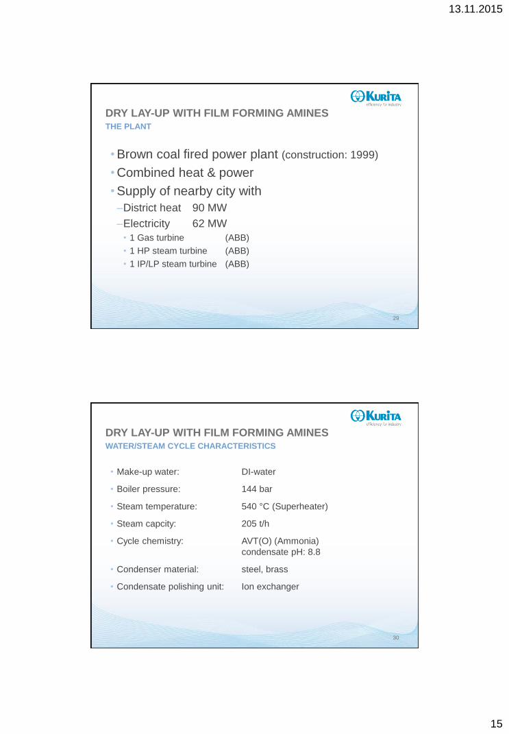
•Brown coal fired power plant (construction: 1999)
•Combined heat & power
•Supply of nearby city with
–District heat 90 MW
–Electricity 62 MW
• 1 Gas turbine (ABB)
• 1 HP steam turbine (ABB)
• 1 IP/LP steam turbine (ABB)
29
DRY LAY-UP WITH FILM FORMING AMINESTHE PLANT
• Make-up water: DI-water
• Boiler pressure: 144 bar
• Steam temperature: 540 °C (Superheater)
• Steam capcity: 205 t/h
• Cycle chemistry: AVT(O) (Ammonia)
condensate pH: 8.8
• Condenser material: steel, brass
• Condensate polishing unit: Ion exchanger
30
DRY LAY-UP WITH FILM FORMING AMINESWATER/STEAM CYCLE CHARACTERISTICS

13.11.2015
16
• Acid conductivity: approx. 0.1 µS/cm
• Fe (AAS graphite tube): < 2 µg/L
• SiO2: < 5 µg/L
As of 2009 decrease of heat consumption
Therefore, economic operation not possible during summer
=> Dry lay-up for 4 to 5 months necessary
31
DRY LAY-UP WITH FILM FORMING AMINESWATER QUALITY ACCORDING TO VGB-S-010
•Conventional dry lay-up not satisfying–Complete emptying of units impossible
(sagging tubes & parts)
–Plant not equipped for Nitrogen blanketing
–Start-up condensate contains high Fe levels
(e.g. in 2011 ca. 50 to 90 µg/L)
•Re-engineering of plant too expensive
•Dry lay-up with filmforming amines
32
DRY LAY-UP WITH FILM FORMING AMINES

13.11.2015
17
• 1 month before shut down changeover from ammonia dosage to film
formig amine based product
• Dosage of undiluted product proportional to make-up water using same
equipment
• By-passing of Condensate Polishing Unit
• Control parameter in main steam and condensate:
– FFA concentration > 0.2 and < 1 mg/L
– pH > 8.8
– Acid conductivity < 1 µS/cm
(additional measurement of degassed acid conductivity)
• Feeding of turbine with warm dried air during shut-down
• Restart of water/steam cycle with ammonia
33
DRY LAY-UP WITH FILM FORMING AMINESPROCEDURE
Parameter Unit Specification Measurement
FFA
Conductivity
Direct
Acid
Degassed
mg/L
µS/cm
µS/cm
µS/cm
> 0.2 and < 1.0
< 1.0
0.1 - 0.6
5.5 – 7.5
0.9 – 1.2
0.2 – 0.4
34
Dose rate: 20 mg/L make-up water
100 mg/L make-up water (last days)
DRY LAY-UP WITH FILM FORMING AMINESCONDENDATE PARAMETERS WITH CETAMINE® IN 2012

13.11.2015
18
• System free of corrosion and deposits (visual inspection)
• Start-up condensate fully in spec within 5 to 12 hours
• approx. 24 h gain in time
35
Start-up
condensate
Conductivity
[µS/cm]
Acid
conductivity
[µS/cm]
O2
[µg/L]
SiO2
[µg/L]
Na
[µg/L]
Fe
[µg/L]
Cu
[µg/L]
Specification < 5.0 < 0.3 < 20 < 30 < 20 < 20 < 10
Measurement
2012
2013
2014 #
3.89
6.25
3.04
0.29
0.18
0.28
14
n.d.
n.d.
< 5
< 5
17
< 2
n.d.
n.d.
< 2
< 2
8
< 1
n.d.
n.d.
# after 4 h; start-up of turbine delayed by non WSC related issues
DRY LAY-UP WITH FILM FORMING AMINESRESULTS
36
Main feed water tank Raw condensate tank
COMPLETE STAND-BY PRESERVATION
DRY LAY-UP WITH FILM FORMING AMINESPICTURES OF PLANT INSPECTION 2012

13.11.2015
19
37
Main feed water tank Degasser dome
DRY LAY-UP WITH FILM FORMING AMINESPICTURES OF PLANT INSPECTION 2013
COMPLETE STAND-BY PRESERVATION
Successful dry lay-up of water/steam cycle with film forming
amines
Complete plant protection due to hydrophobic protective film
Significantly lower iron levels in start-up condensate
Faster restarts after shut-down periods
Long lasting film stability under wet and dry conditions
Highly felxible treatment concept tolerating flexible system
operation
No need of dry air or nitrogen
38
DRY LAY-UP WITH FILM FORMING AMINESCONCLUSIONS

13.11.2015
20
39
40
13.11.2015
21
CONTACT SLIDE
Andre DE BACHE
Technical Product Manager Boiler Water
Niederheider Straße 22
D-40589 Düsseldorf
Phone + 49 (0)2 11 797 84 10
Email [email protected]
Web www.kurita.eu
THANK YOU FOR YOUR ATTENTION
Learn more by visiting
www.kurita.eu
This document is confidential. Any kind of reproduction, change, transfer to a third party or disclosure of this document,
even extracts, requires the prior written consent of Kurita Europe GmbH.