filter and filizr elemefws, fluid mssm. hyd~ulic...
TRANSCRIPT
/“,0 . . . . .
. .
(.-
MIL-F-8815Dz ~der 1976SUPERSEDINGMU-F-SE 15C29 September 1972
MLiTARY SPECIFICATION
FILTER AND FILIZR ELEMEfWS, FLUID mssm. HyD~ULICLKNE, 15 MICRON ABSOLUTE AND 5MICRONABSOLUTE,
TYPE II SYSTEMSGENERAL SPECIFICATION ~R
Tbfs specification le apprmmd for use by all Departmetiand Agencies of tbe Depmlxnent of Defense.
1. SCOF73.
1.1 * - This specfflsation covers hyd.nmlic line filter aet3em-biies cnd filtar elements wMch mtaln all particles larger than 15 nticrmm and 5micmne end are suitable for use se specked In 6.1, and tk applicable specifien-tfmt elmet.
c 1.2 Cinsslfieation - Hydraullc EUter assemblies shall he of tkefoilowfng type, class, styles, micron ratfngs, end sizes. as specified (see 6. 2).TIMhydraulic filter element sbsll be ettlk?r cleanable or noncleanable as specified .tn b appikabla specfficatlan sheet.
)
c
Ty’p If (MIL-H-5440) - For -820F to +27SoF fluid temperature ranmClam S000 (MIL-H-5440) - Filterandfilterelementebalibefirnished
suitableforoperatingp18sEun3sup to andIncludfng 9.000 pamde per square inch fpsi).
Sty@e. eizes, micron mtings, and part nambers ehslf he as specified lothe applicable specificatim sheet.
2. APPLICABLE DOCUhlENTS
2.1 Is’sue of documents - Tbe following documente, of tbe fseuefo effect cmdate of lnvttstlon for bide or mqueet for pmpoeai, form a pert oftMs epeclficatlon to the extent spectlied bamln.
~,
peaUnent data wMch may ha of USEIn fmprovlng Uds &oument should
(Code 8211) Naval Air En@neerlng Center. I.akakret, NJ. 087S9 by
peeaf (DD Form 1426) appeming at the end of thie &cumest or by letter.
m
Downloaded from http://www.everyspec.com
.,;
I
Mm-F-8815D
SPECIFICATIONS
PPP-B-566
PPP-B-636
PPP-B-676
Military
MIL-P-116
MIL-B-117
MIL-H-5440
MIL-C-5501
MfL-H-5606
MIL-H-60S3
ML-H-6775
MIL-H-25475
MIL-F-61836
MIL-H-83282.
STANDAR~.,lwitttary
MIL-STD-1 OS“
.MIL-STD-129
MIL-STD-130
MIL-STD-’794
2
Boxes, Folding, Paperboard
BOX, Fiberboard
Boxes, Setup
Preservation, Methods of
Bag, 51eeve andTubing-InteriorPackaging
Hydraul.tc Systems, Aircraft, Types Iandff,De-sign,Inatallatfon, and Date Requirements For
Caps and Plugs, Protective, Dust and Moisture Seal
Hydraulic Fluid, Petroleum Base, Al,m’~, Mitisileaud Ordnance
Hydraulic Fluid, Petroleum Base, for Preservationand Testing
Hydraulic System Components. Afrcreft end Miesfles,General Specification for
Hydraulic System, Miaaile, Dasfgn. fnstaUation, Teetsand Data Requirements, General Requirements for
Filter and Dieposai Element, Fluid Pressure, Hydraulic3 Mfcrnn Absolute
..-
I
.-
..”
Hydraultc Fluid, Fire Resfetant, Synthetic HydrocarbonBase, Aircraft
Sampling Procedures and Tables for IqapectIon byAttributes
Marking for SbIpment and storage
Identification Marldng of US Military ProIw@Y
Parts and Equipment, Procedures for Packagingand Pecking of
;.
.
. .
. .
Downloaded from http://www.everyspec.com

MIL-F-8815D
c Military (contd)
MIL-2TD-SI O Environmental Teat Method
AN815 Union, Flared Tube
AN929 Cap Assembly, Pressure Seal Flared Tube Fitflng -
AND1OOS4 Fifflnge, Installation of Flared Tube, StrelghtThreaded Coaaedors
63A109 Cleaning Machine Hydraulic Fflter Element
PUBLICATIOti
Air Force
AFTM-T. O. 9H3-1-1 Cleanhxg end Testing fnetructione for WovenWire Hydraulic Filter Elemeata
(When requesting a~licable documents, refer to both title end number.Coplea of ooclaedfled documents may be obtained kern the Commanding Officer.Naval Pubiicetione atxl Forms Center, 5801 TeborAvenue,Pbiiadelphfa,Pennsylvania 19120. Rqueste for copies of cieaatfied documents atwuid be
(addreeaed to the Navel publications and Forma Center, via the cognizantGoveromeat repreeeotative).
● 2.2 other pub iicatione - The following documeata form a partof this speciEcaiion to the extent specified be rein. Uaiesa otherwise lndiceted.the iaaue in effect on date of invitation forbide or request for proposal shall apply.
Soziety of Automotive Engineem
ARP 598 Procedure for the DeterminationofPexticulateContaminationof Hydraulic Fluids by the Peticle Count Method
ARP 785 Procedure for the DeterminationofI%tiicolateContaminationinHydraulicFluids by the Control Filter Gravimetric Procedure
(Appiice.tion for copiee abould be addreaeed to the society of AutomatizeEogfneere, 400 Commonwealth Drive, Warrendeie, PA. 15096).
3
Downloaded from http://www.everyspec.com

. . ,
MIL-F-8815D
AmericanNationalStandardsInstitute.3
ANSI Y14. 5-1973 Dimensioning and Tolerencing for EngineeringDrlm@ge .
(Application for copiee should be addreesed to the American NationalS~&rde IIIStibJtS, 10 East 48 Street, New York, New York 10017. )
National Aerospace Standards Association, Inc. Standard
NAS 1638 CleanlinessRequirementsofpartsused inHydraulicSystems
(Applications for copies should be addressed to the Nationaf Aerospacestandards Association, Inc. , 1321 Fourteenth St. , N. W., Washing% D. C.20005) .-.
3. REQUIRE~NTS >.:.
3.1 Spec ifications sheets - The individual part requirements shellbe as specified herein qnd in accordance with the applicable ep&ification sheets.In the event of conflict between tie requirements of this specification and the Yspecification sheet, the requirements of the specification sheet shell govern.
d● 3.2 Qualification - The filter assemblies end.51ter elementsfurnished under this specification efmll be products which are qualified forlieting on the applicable Quelifi.ed Products U* at the tie set for Pingof bide (see 4.4 sad 8. 3). In addition, the retsntion of the qualiflcatign forthe filter assembly end filter element on the applicable Qualified =cteList shall be @endent on periodic verificatkm of continued compliancewith the requirements of this epeci5cation (see 4.3 (a) (l)).
3.3 General k ification - The requirements of MIL-H-S775 apply
1as requirements of this specification with the exception end additions specifiedherefn. when the two specifications confiict, this specification shall govern.
3.4 Materiels -
3.4.1 Compatibili~ - The filter assemblies end filter elements shallbe constructed of materials that will not adversely effect or. be affected byhydraulic fluid conforming to IKIL-H-5606, MIL-H-6083, IKfL-H-83282, end thetest fluid included herein. . .
--a
.44
Downloaded from http://www.everyspec.com

. . ..
MIL-F-3815D
(
.—
-(.,.
3.4.2 Cleanable filter elemente ehell be constructed of mstertalathat will not be adversely tiected by the cleanfng procedun?a apectfted in4.7.2.6.2.3.
3.4.3 Process contmlem Umttetions - If the filter element le of tbetype wberetn reetnoue or other matefiat te used for ettmfnstton of imperfections,not more then 5 percent of the filtming ama shell be covered by tbe appliedmaterial. Filter eiement medle having an initief Ixbble point of leas than 3inches of water before repair ehail be ceuae for mjectkm. The manufacturer’squalification test report shall deffne the resfn employed for joining or patching,eppiicetion techniques, curing cycle, age lfmttatton, and procedures foliowedto tnfsnw adhesion of the resin. Tbe mfmufactumr’s drswfng ehatf epecify tbeUmitettene or process ccmtrola that wiii govern manufacturing variations inmedfs ob.vtmction &e to brass wlcklng, seem width, end crtmp length in additionto the exietfng itmits on repaIr.
● 3.4.4 Filter element repair mocedmes (For cfeanabie elements~ - Ftlter element ,repetr proctxbres ebafl be submitted for sppmvel to ttk?activfty reeponsfbte for quatlftcatien with the qualification test repert. Theserepair procedures ehall specifY, tmt shall not be limited to tim restn employedfor Jotntng or patcbtng, application teclmiquee, curing cycle, procedures to befollowed to insure adheaien of the xeein, and epecta.t tools and test equipmentmxfuired.
3.4.5 m- FUter etement meteriale that are subjected to agingshall be fully defhmd. Age ltmitatioo for tkse matertals shall be specified inthe qualification test report.
3.4.6 Fuogf nutrients - Materials whtch am not nutrfents for fungfshell be used wtunwer poesible. Where fungus-nutrient msterinla must be uee~tks?y shall be treated wltb a fungtcidal agent acceptable to the procuring activity.
3.5 f)sSi~ end COllStNCtiMl -
● 3.5.1 Filter assemblies and filter elements. for hydraulic systemsconforming to ML-H-5440 and MIL-H -25475, abalf be deel~d and conetmctedas specified herein and fn the applicable specificaUon sheet. Filter assembliesshell be of such deet~ and conetmction that the elements may be removed foreervfcs and inspection without discmmectfng fitttnge or diafufifng mcsmtfnge.Nltar eeeemblies shall be so designed that Uuid entering ttm ftlter bmsing cannotimpinge directly upon element filter medium or upon the reltef valve poppet. ‘i%efilter assemblies snd Elter elements shall be capable of withstanding 2,000 hwrs
. of operation at 275° Ffluidandambienttemperature.The manufacturershall
. . . . 5
Downloaded from http://www.everyspec.com

,,
MIL-F-8815D
wrKv con@tenoe with thts m@rament by analysis. rnfferenttal preesureindicators end pmesure relief valvee (except for the valve seat) .sbeil be of amodular deetgn and cepeble of I@ng readily removed from the altar assembly formplauement.
3.5.2 Nlter aaeeqbltee end filter elemcnte ebsil be of the full-flowt=. The flow through tiw filter elements ebaU be from “outetde-in”.
~ 3.5.3 The dee@ of ftlter eaeembliee ebeU be euch that the interelement cannot be tnstalled reversed.
3.5.4 FUter Imcain@ shall be designed to wttbatend SU the atnmturailosde impeeed by the fcncttcnal test requirement of tide epact5cation. In addition.the filter lmuatng and mocnttnge Bbeli be of euch strength end rl@dt~ es to wlth-stsnd tlm wrench loads requtm+ for msklng tuba comacttcne tn accordance wtthAND1OO64 and the replactng of fUter elemante.
3.5.5 Intercliangeabiu ty - It ebail not be poaatble ta tntercbenge filterbowls and bade between the w@ocs eizee of fUter eeaembltea, exoapt that -4,-6, and -8 eir.ae ehsU use the same bowl.
3.5.6 Protective davlcee -
* 3.5.6.1 Filter element relief valves - FUter eiement praesure reliefvalve when requtred hy the applicable epecificatlon street, ehsil meet the raquira-ments of the applicable specification ebeet and the requirements end taste spectfledhereto (ace 4.7.2.9).
3.5.6.2 Nlter zasembly reitef valvee - Style A filter essembliee ehaUtnccrporate a suttable rdtef valve to permit bypassing of the bydreultc flctd in theevent of excessive raettiction @ flow through the filter element. Tba relief valvecracking pressure ebaU be 100 + 10 psi. Reeeat pressure ebaU be 65 pei minimum(see 4.7.1.3. 1). Thaee preeeuree apply over the tMi tempmature remge of -65”to +275”’F. No relief valve shell be incorporated tn style B filter easembites.
.3
3.5.6.2.1 The relief deai~ sbaU ha such that no maltimcticio can occurdue to flow eu~e up to 150 percent of the mted ftcw of the fflter. At 150 percentof rzted flow through the reitef valve end at 10iP ● 10” F ftutd tamparatuzw thediffemnttal pmaeure acmes the relief valve ehell mt earned 240 pat.
;,. ,6.5.6.2.2 “ Tba raUef tmlve design abaU be of the ncnzdjuetatile type.
l.-3.5. 6.2.3 WItb the filter azeembly installed with the bowl @low horizontal,
the design eball incorporate provision to prevent inbcrne contaminen tafromsccu- ~mulating or settling where ent@nment with reiief valve flow will occur. >
6 ,,. ,..
,..
Downloaded from http://www.everyspec.com

. .
c
(
MIL-F-8815D
● 3.5.6.3 LXfferential preaaure tndtcator - FUtar assemblies ebelllnoorpotate en tntegrel nooelectrtcal davtce that wtll gtva vtauat wemtng byI@atng a red lodlcator when the dtffemntial pmssum acmee tfm element exceeds70 ● 10 patd. Inadvertent actuattng shell mt occur under a temporary flow a-or a 20g stmcfc [oed. ~roel contamlnetton ekatl not advereely effect tba mmnaloparetton of the dtfferenttel pressure fndlcetor. U nacesaary (such as for low ~actuation force) dastgn feetmws ebell be Incorporated to provtde the indicator pinwith poalttve protacttoo egatnat external conteminan ta Wtltch mt@lt tmpada normalopam.tfon. -e actuated, the red todicator shell Iwmatn extended untit maetmanually. Wban the tndicetor fs tn the maet poattton, it shell be htddan fmm vtew.Tba tndlctir ehafl not actuate below 100” ● 15” F flutd taropemtum. The tndtcatoreball be red fn color.
9.5.6.4 Automettc shutoff - 6tylea A and B ftlter tmuetnge shall bepmvtded wttb so eutomattc ehutoff davtce to prtwrmt dminaga frwm tlm flowbetween ttm fnlet and outlet pxte of the filter heed when the flttar bowl endelement am removed, end to pmvant atr tncluaton fn excess of 2 cc. upon re-assembly. The davtce for style B filter fweingao shall allow rated flow throughtfm ftlter Laxu3tngat a dtfferenttaf preseum not to aacead 200 pat tn the event thattfm fflter element 1s not tnatalled to a filter aaaembly. TM davtce abalf @sa t~leakage, cycttng, end atr tocluaton teats apactftad under 4.7.1. S. 3.
3.6 “ Performance - “
● .S.6.1 Ftlter eaaembllea, ftltar fxmatngao end filter elemante shallperform sattafactortly when subjected to ttm tests spectfted hereto.
3.6.2 _ - Ftlter eaaembltes 6hell w@atand 25,000 tmpulaecycles at 275” F flutd tempamtura and 75,000 impulse cyclee et 225” F wttboutevldeoce of leakage or .3tIuctumd fdlure.
3.6.9 Eouatng end element praaaum drop - The maxfmum p n e a umdrop et mted ftow between tb blat end cmtlet of ttm filter kmatng only, shall mtexceed 15 pat wttb a fzwa-tlow dummy element tnatalled (s88 4.7.1. 2). Tbs .maxtmum pmasum drop at rated flow acmaa the ~r element shall mt exceedtk value specified tn the applicable specification sheet. \
3.6.4 Burst preesum - Nlter kesembltes shell withstand a burstpmsaum of 7,500 pat.
c
3.6.5 Proof pressure - Ftlter eaeambltse ebell wttbeteod a proofprmmurw of 4,500 paf at 275-F fluid temperature.
7
Downloaded from http://www.everyspec.com

.,-.,
MIL.F-8815D
3.6.6 Filtration - Filter element efficiency shall be ee specified intbe applicable epeciflcation sheet.
3.6.6.1 Fitter eiem60t sbail not unioad wban awbjactad to intennittant .hydraulic puking or etati up flow conditions as found in typical bydrmdic ayeteroe.
3.6.6.2 Filter elemente abail not be aenaitive to veriatione in con-taminant concentmtion, type sod/or distribution above tba ebaoluta rating.
\3.6.6.3 Filter elements eball be so deeigmid tbet under gormd
bendlfng tba filter media wtil not be damnged or degraded.
9.6.6.4 Niter element ftltemiag media conetmction ebaif be such thatit is O&taffected by tbermei cyc~ and preesure/fiow cyciiog. Nnrmel operationabail not cauae contimmua or spbradic reiesee of the media, binder and adhesiveif used.
● 3.6.7 Media mi@I Uon - Niter essembiiea aball wltbetand vibrationfrequenoiea in accordance with 4.7.2.8.3.2. Tbera shall be no media migrationtracesble ti tbe fitter element or Ma packaging (See 4.7.2.8).
3.6.8 Element coilapae - Filter elements abali witbatand a differentialpreeauxw aa specified in tbe applicable epacification ebeet. .,.,
3.6.9 Bubble point - Tba initiai bubble point veiues abail meet tbevalue establiabed by the activity raeponaible for qualification and ebell be determinedSE specified in 4.7.2.1.1. All elements submitted to tbe quali& conformance bubbleteet aball meet the vaiuee eatabliabed.
3.7 Ma- -
3.7.1 Direction of fibw - Tbe direction of flow aball be cleariy andpermanently indicated by at ieaat two arrowa marked on opposite sidee of tbefilter body.
3.8 kienttficatIon of product -
6..
Downloaded from http://www.everyspec.com

. .
c
-(_-
MIL-F-6815D
● 3.8.1 Fitter bouaiq - Each filter housing shail be clearly andpermanently identified by steel atamptog, electro-etcttiag, or by a pernxm~tly’attached nameplate confonnktg to MIL-=D-1 30. The following tie-on e~lbe pxmf&d:
YILTEFL FLUID PRESSURE, EYDRAULIC. S, 000 PSI (taaert micron rating)AuCRONS ABSOLUTE, MAXfMUM TEMPEW~iL5 275* F M6815/ fbaetielasb number of epecti3catton sheet nod size dash number)Maoufaciumr’s pati No.Manufiwtumr’s eeriel No.Manufantumr’s name or tmdemarkReplacement element M6815/ (insert elaah number of epec~caflon eheet
end size dash number)PaR number(s) preformed packtng seatsAssembiy tmque for bowi
● 9.8.2 Filter eiemeot - Each filter element shaii be cieariy andpermanently identified on one end by ateei stamping, eiectm-atcfdaR, or~Y apxmaaantiy attncbed admepiata in accordance with MU~D-130. Tba methodof marking ahaii he in accomfance with MIL-~D-130. The mazkfng aheil notbe placed on a eeatlng emface. the maridnga zhell not affect the seating of theeiament. The foilowfng information ehaif be provtdad:
M8815/ (insert slash number of specification efmet and aiae dash numbsr)Manufacturer’s pati No.~~rle sefiai No. (Cleenabie elements OUW)bfan~cturer’s Lot No. @oncleanabie elements only)Manufacturer’s name or tradama*
Cleanable or mmcleznableMaximum pressure drop after cleanfng (Cleanable eleman~ oaiy see4.7.2.6.2.2.1)
3.8.3 Paxt numba~ of iotan+u!qp able paRe - The manufacturer’spafi number and drawing number sbail be the came.
a. 9 Woricmensidp - AU detailci of wmhnanahtp shail be of asufficiently high grade to insure propar opemtion.
4. QuALITY ASSURAPJCE PROVISIONS
4.1 @lW3rSi - The qufliity ~sw~ PrWiSiOOS ShSit bS h
accordance with MIL-H-8775 iind as spaci5ad fmmin.
9
Downloaded from http://www.everyspec.com
. .
MIL-F-8815D ---!● 4.2 Reepn risibility for inepec tion - Unless otherwise epecifiedin +tbe contract, thecootracti.r isreeponsible fortbeperfodce ofall Loepectionr-iremmte es specified herein. Except se otberwi8e epecifted fn the contract,the contractor may use his WSor any other fmiilities eutteble for the performanceof the inspection requirements specified bereh, unless disapproved by tlm Gov-emmant. l%e Government reserves the right’ to perform any of the inspections
,.
set forth in the specification. Where such ioapectiooe are kmed naceskary toassure euppliee and servfces coqform to preecrlbad requirements.
I 4.3 Claasificatlon of tests - The inspection aod testing of fil@rsshall be classi5ed se follows: “,
(a) Queltfication teeta (4. 4)
(1) Raieotion of qualification - Ratentton of qualificationconatate of a periodic ver@catton to determine compliance of the qualified productwith the mquiremente of thte s~cificatIon (s4 3.2 aod 4.4.4).
(b) ~titY confo~ce inspection (4. 5).. .
4.4 Qoaltficatton tests -
4.4.1 Filter bowing - ..
4.4.1.1 3aroples for qualification tests ,of ftlter housings shall consistof two specimens of each device upon wtdch qualification is desired.
4.4.1.2. The specimens s@dl be assembled of parts whtcb conform tomenofhcturer’s drawings.
4.4.1.3 The manufacturer shall provide calculations showing thatadequate clearaoce of movfng parta Is provtded at -65” end +275° F, tiing tbemost adverse dimensions. The mom tamparatore reference pofnt shall be 70” F.
) .- 4.4.2 Ftlter elements -
4.4.2.1 Qualification test samples of filter elements (cle~le andmmcleanable) shall consist of eight elements of each stze upon whtch .qoaltficationis deelred. Manufacturer’s que~cation teats shell not have bean performed “onthese samples. The manufacturer shall submtt reporta of the qualt5cation testson other specimens of tbe same design. A aubmtttat pmcedum atmtlar to thatoutltoed for filter bouefnga eball than be followed. r
,. .1,
10 1’
Downloaded from http://www.everyspec.com

.. . .
cMU-F-6215D
4.4.2.2 If the elements are of the type in whtch repair mstertalIeappliedtoeltmtnateimperfections,thequaltficattonteatelemeotesheU haveamtntmum of 5 percent of tbe ftltarlng area repaired. Tlm areaa repaired ebellotmtain at least three tmparfectiona wboae tnttlelbubble point te 3 tnclms ofwater or teas.
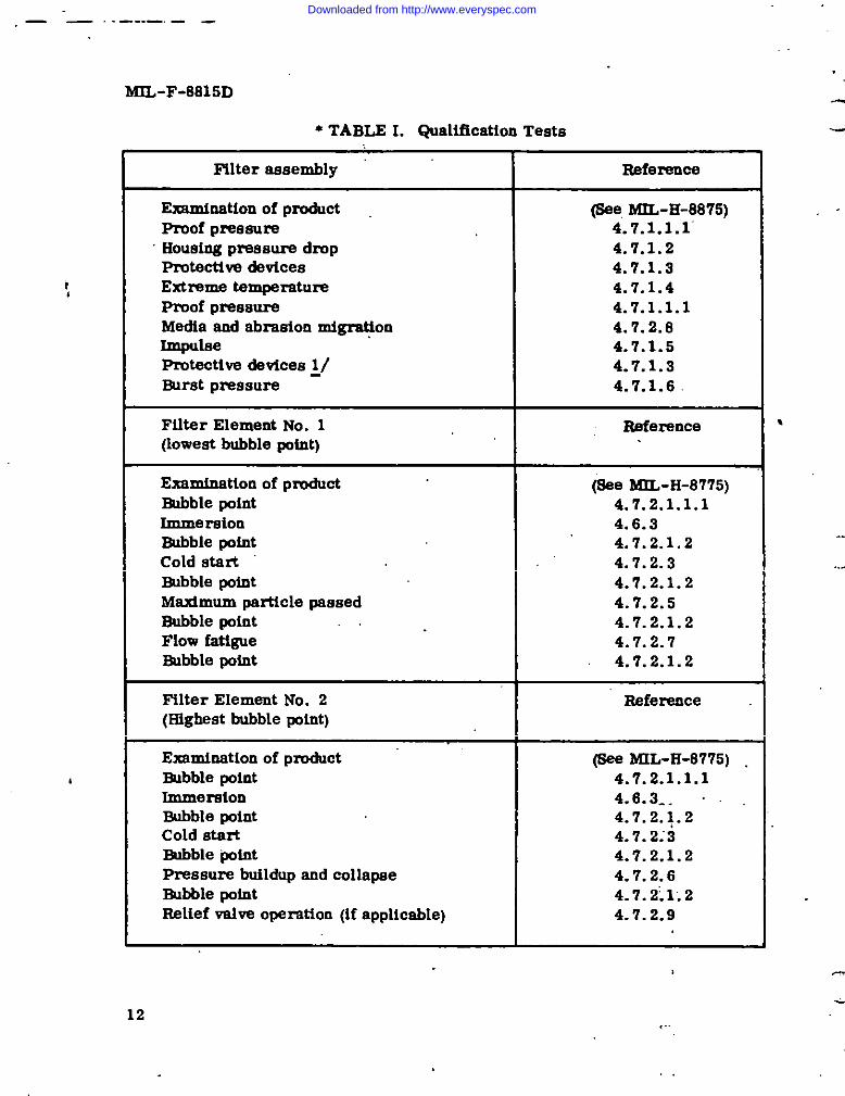
4.4.3 Teeta - The qualiftcatton teats ebell cooaist of tbe teateapectffed under 4. 7~&cted on the applicable epectmene, to the order specifiedtn Table L
● 4.4.4 Retention - The retention of qualtficatlon abetl oonetet ofpertodlc veficatton to detenntne oompllence of tbe qualified filter +esembly and~lter element wtth the requtremente of thts apeoiflcatton end applicable epectficattonafte6t. Verlficstton ebatl kmconducted at lntervale not exceeding 2 yeere.
4.5 Quality Ccmformanc e tnapectton - Quality cmformencethepectton abaU camtet of the foUowlng:
(a) Kndlvtdual tnepection (4. 5.1)
((b) Sempung teete (4.5.2)
4.5.1 Indtvtduel tnspe ctton - The tndtvtdual fnepecttnn, epectftad inTable II, shall be conducted on each filter tuustng and filter element in that order.Any fUter tmetng or filter element contalntng a defect sbel[ be rejected.
● 4.5.2 31m@ng taste - A aemple shallbe eelectedfzwmeachtOEpaOtiOn!ot(eee4.5.3) in accordance wltb MfL-Sl’D-105 ustng apicial tnepectIonlevel s-1 wttb no rejecte allowed. The sample filter assemblies aod filterelements abeU be unpacked and the eampltng taste, epecifled to Table U, shallbe mndactsd on each filter assembly md ffltar element in that order. For filterelements one betf of tbe eamplea ebatl be subjected to the preaeure btdldup endcottapee test end one hatf of ttie earnples sbatl be eubjected to ttm degrwe offiltmtton teat. When the total number of eamplee te en odd number. the oddeemple ebd[ be eubjected to tbe pmasum fxdldup and 00uspas test.
4.5.2.1 “ Cleanlloese - To assure that tbe filter elemenW and tmuelngS?S ~ c1- properly, end to aeeure U@ the parts are not contaminatedm [email protected]~ ffl~r ele=te or =sembttes e~U ~ mk~ eodteeted for clmaltnee eee epectfie dtnpareg’reptq 4.5.2.1.1 and 4.5.2.1.2.FUter elemente shell be toetelled IO a precleaned tiuetng.
11
Downloaded from http://www.everyspec.com
,— —. .—. .— ___
MIL-F-8815D
* TABLE I. Qualiilcatlon Teats
t
I ,
Filter aeaembly Reference
Examination of produCt (Bee, ML-H-8875)Proof preeeure 4.7.1.1.1’Housing preaaure drop 4.7.1.2Protective devices 4.7.1.3Extreme temperature 4.7.1.4Proof pressure 4.7.1.1.1Medta end abraeion mtgmtton 4.7.2.8IlnpulBe 4.7.1.5Protective devices ~/ 4.7.1.3Buret pressure 4.7.1.6
FilterElement No. 1 Heference(Ioweet bubble potnt)
Exarninatlon of productE!ubble point
(6ee MIL-H-8775)4.7.2 .1.1.1
Immereioo 4.6.3Bubble pofnt 4.7.2.1.2Cold Stert 4.7.2.3Bubble point 4.7.2.1.2Maximum particle passed 4.7.2.5Bubble point 4.7.2.1.2Flowfat@ue 4.7.2.7Bubble point 4.7.2.1.2
Nlter Element No. 2 Heference(Highest bubble potnt)
Examination of product (6ee MIL-H-8775) .Bubble point 4.7.2 .1.1.1Immeraton 4.6.3-.Bubble point 4.7.2.1.2Cold start 4.7.2;3Bubble “~tot 4.7.2.1.2Pressure buildup and collapae 4.7.2.6Bubble pofnt 4.7.2; 1.2Relief valve opexation (if applicable) 4.7.2.9
12
Downloaded from http://www.everyspec.com

. ..
(
I W I GF - 8 8 1 5D
TABLE I. Qualification Tests (Cent’d) .
Filter Eiement No. 3 Reference(2nd ioweet bubble point)
Examination of product (See bfIL-il-8775)Bubble point 4.7.2 .1.1.1Immereion 4.6.3Bubble point 4.7.2.1.2Cold atati 4.7.2.3Bobble point 4.7.2.1.2Degree of filtmtion 4.7.2.4Bubbte point 4.7.2.1.2
Filter Element No. 4 Refertmce
Eaamfnation of product @ee ML-H-8775)Bubblepoint 4.7.2.1.1.1hnnie~ton - 4.6.3Bubbiepoint 4.7.2.1.2Flueb 4.7.2.2Cold etart 4.7.2.3Bubble point 4.7.2.1.2Media and abreaton migration 4.7.2.8Bubble point 4.’7.2.1.2
~~ Make functional checke only ooe time, omitting any r6quired repeated cycling.
VABLE IL Quality Coofonnance Tests
Individual teat Reference. .
Filter HousingExamination of product (See BnL-E-6775)Proof pressure 4.7.1.1.2Protective devices
Reiief vaive “4.7.1 .3.1.2Dfffereutiei preseureindicator 4.7.1 .3.2.2Automatic ehutoff 4.7.1 .3.3.1.2
Filter eiements oniyExamination or product (See MIL-H-8775)-W @* rmance bubbie point 4.7.2.1.2Filter Element preasum drop (cieenebleeiements) . 4.7.2 .6.2.1
Filter eiement relief vaive (if eppilcabie) 4,7.2.9.2
.13
Downloaded from http://www.everyspec.com

. . .
MIL-F-8815D
TABLE IL Quality Conformance Teste (Cent ‘d)
7.. .
Samplingteats Reference
Filteraeeemblieeand61terelementsCleanliness 4.5.2.1
FilterelementsPressurebuildupendcollapse 4.7.2.6(OneloadingonlytaappiicatdepressuredropspecifiedfnTable 1 of epeciflcation eheet -no samples taken)
Degree of filtration 4.’7.2.4(Filter element efficiency)
4.5.2.1.1 Vibration - The iliter assembly, filled with tlm test fluid,ehali be vibmted for 15 minutes at a frequency of 120 ~ 10 cps and a doubleamplitude of O.014 inch in a direction pareliel to the bowl axle of the assembiy.
4.5.2.1.2 Degree of cleanliness - The filter sesembly”abail be tranaferradto a staod and flush with 2,000 miiliilters of prefiitered hydraulic test fluid atrated flow. and the effluent collected. The contaminant ievei of tb effluentSample SWI ha determined in accordance with ARP 785. The contamioent valueobtained shell not exceed 1.75 milligrams maximum.
..
* 4.5.3 Inspection iot - For p u r p o s e a of quality conformanceinspecting, a iot shall be defied as all fflter aesemkdiee manufactured underessentially the same conditions and offered” for acceptance at one time, or allfIitSr elements _ufactumd fmm one convoluter act-up. Elements wufacttu=d.in excess of contract quantity may be piaced fn stock end accepted for later con-tracts (within 3 years) based on prior tests of the specific lot.
4.5.4 Repoti of faiiure of sampiimg teat - When a ftMerelementfails to pass a sampling teat, the entire iot represe~d sbaii be rejected. AU
,. faiiure of the teated units and elements sbail be rspofied immediately by tele-phone or meesage. Full Pafiiculare concerning previous simtiar, feiiures, thecurrentfailures and action taken to correct the defects sbeil be submitted ta theprocuring agency in wrttfng. The iot repreaentad by the unsatisfactory sampleshall not be msubmttted un~l apprtwai of resubmiaaton baa been Issued by theprocuring agency.
4.6 Test conditions -
I 14
,,:
Downloaded from http://www.everyspec.com

. .
MIL-F-8815D
c 4.6.1 Teet fluid - Uniess otberwiee spectfietf, the bydreufic fluidused for eli teets shell conform to MIL-H-5606 (with on fme water). For qualityconformance tests, hydtauiic fluid conforming to MIL-H-6083 or MIL-H-5606(with no fmM water) maybe used.
-* 4.6.1.1 Test ftuid cleeniineas - For quatttj confonmmc e tests endcrtticei quefificetton teats the test fhdd ebell be. precleeoed to a clemees Ie@equal to CiSSS 1 of NAS 1638.
● 4.6.1.2 Test ftuid filtretton - Unless othemiee speciiied, the testftuid shell be continuously ftltered through a %micmn absolute fflier conformingto MIL-F-S1SS6(A.9) or a filter with equivcleot eiltciency during testing.
4.6.1. S Test fluid te mpereture - uniess othexwtse epecifled, theactual tempemture of the test ftuid ehail be 100” * 10” F.
4.6.2 Temperetam - Unlese otherwise epecifled, the tests sbeU becintducted at a mom tempexatum of 70” to 90” F, measured within 12 inches ofthe test sample.
4.6.3 Immersion - Prior to performing the quelifioeiion tests, filterelements shalt be immersed in bydreultc fluid (see 4.6.1) for a period of 72 @Jre
(at a fluid temperature of 275” F end 72 bum at a fluid tempemtum of -65” F. Allinternsl parts ehell be in contact with the test fluid du~ tide period. Afterimmersion, tb filter ehall mmato in this fluid at room temperature unffl futhertests are conducted.
4.6.4 Test sir - The sir used b pmesurtze the test apparatus sheifbe mtered thmugba O.4S-tttictwn membrane filter (type EA hfillipore, or equiv-Sieni) .
4.6.5 Weight, meeeummant of -
4.6.5.1 Precision (of WetgtdnQ - Uttteee otbe=iee epecified, allWOQ@S SW be measured with a precisfon of one part in one thousand or better.
4.6.5.2 Static electricity, elimination of - A desice to eliminate staticelectricity shell be in proximity to the filter memb renediec, ortoiim penonwhich it =s, wimnever SOYobject or materiel is being welg~ to a precision of* 0.1 gram or Hner. Ttm ago of tlm device ehall not exceed tb value stated bythe manufacturer as its xated eervfce life. .
c 15
Downloaded from http://www.everyspec.com

MIL-F-8815D .-
* 4.6.6 Test duet, source ofsuppl ~ - All teet duet ueed for teete eballbe obtained from the Naval Air Jletilopment Center (NADC), (Attention of Code30211), Warmineter, Pa. 18974, and AsH be the lot of teat duet curmntiy in uaeat NADC.
,. ,.4.7 Test metboda - -
4.7.1 Nlter aeaembiy -
4.7.1.1 Proof prestire -
● 4.7.1.1.1 Proof pressure (Qualificatio~ - Fiiter aeaemblies sbailwithetand proof preaaore se specified herein without evidence of permanentdeformation, meifuoction, or external leakage. Tim?filter aea?mbly ehall be .filled with teat fluid and maintained at 275” F for 72 hours. Prmf preaaare of4,500 pei sIMI1 then be eppifed at leaet twice whiie at 275° F and beid for 2 minutesat each application. The preaaure shall be reduced to zero between applications. .Tbe activity reaponaible for qualification aball have the prerogative 10 conductadditional teats to vaiidate compliance of the filter aeeemblies tith the iongevltyrequirements apacified in 3.5.1, end veri~ the manufacturerta amiiysis.
● 4.7.1.1.2 -f pmeaure (quaiity conformance) - Proof preasura(4, 500 pet) ahaii be applied at leaat twice et room tempmature end held for 2minutes at each application. Tbe pressure abell be reduced to zero betweenpmseum applications. There, abaii be no evidence of pemnaneat deformation,maifonction or external leakage.
● 4.7.1.2 Housing p&aaure drop - This teat shall be conducted with afree-ffow dummy element Installed to hold open the automatic shutoff. Thefree-flow dummy element s~li be coostmcted to accordance with the applicablefilter element apeci5cation abeet with the X dimension being heid to tbe minimumdiameter abewn. The filter manufacturer shall have the prerogative to furnishthis test dum&y with filtretiori media representing minimum preaaura drop. With
1 rated flow appiied to the filter imueiog, the p~aaure drop ahail not exceed 15 pet.
4.7.1.3 l%otectiva‘devicee - A suitabie means of stopping flow threugbthe fitter eiement port ahali be installed for this teat.
4.7.1.3.1 Eieiief vaitie operation -
16
h“
Downloaded from http://www.everyspec.com

.
. .
h f l L - F - 8 8 1 5D
c 4.7.1 .3.1.1 QueUfication - Style A, ftlter tmuetnge shall be teated forrelief valve opretton. By meane of a power-driven pump, pzessure shatl beapplied to the tnlet port of the ftker hous[ng, begtndog with a pressure of 70psi end tncreestng to increments of 10 psi or less until czncktng pzwaenre of~ mwf vehm ILIthe fflter htmsing batng teated ta reacfmd. At each fUCmJMI%the pressure ehaU he maintained conefant for 5 minutes. At each presaum ti-cmxnent, tlxne shall not be conatdered “tn” or hmkage noted unttl the hegtnaingof ttm thtrd minuts. Ttte leakage rate ckfng the taat 3 mfnutee of each pressuretncmmeat abaU be noted. The pressure at whichtfb?leeka& ratethroughthemllef valve amamts to 8 cubic centfmetera (cc. ) (approximately 160 drops) permhmte shall be conai&md us cracking PreseuIw. CreckiU6 PmSSUIW ~ ~~ret 100 ~ 10 psL Lea up to 80 psi shall not exceed 4 cc. (eppmxima.tdy 80drops) per mfnute. Presaum ehall be i.ncmeeed unttl rated flow thra@ tbs reUefVSIW is obtatned. Ratsd flow shall occur at a pmesum diffexwnttal between inletand tmtlet ports not exceeding 160 psi. ‘flm preaenre abaU be mxbced to 10 psidecrements es atwve unttl teakage thrcagh Um mltef valve dose not exceed therate of 4 cc. per mirmte. ~ mmlting pressure ehall be coaetdemd th? mdiefvalve xweeating preemre and ebatl octmr et a preseum of 65 pei or above. Tbsflow tbrm~ the rellef valve aball be rataed to 150 percent of reted flaw. Tbedifferential pressure across tlm relief valve abatl not exceed 240 p8L
.
● 4. ‘I.1. S. 1.1.1 Rettef valve cnntamioatton tolemnce teat - Style A filterhmetnga eball repeat the Qualification test of 4.7.1. S. 1.1 with the fluid con-taminated to a level of 100 mg/1 with A. C. Ftae Test Ihwt. The crackfng, fuUflow end reseat cycle eball be applied for a total of 100 cyclee. At the end ofeach cycle, the flow shell be reduced to zero prtor to commenctag tbe next cycle.Malfunction or rettef valve damage shall constitute failure of this test.
4.7.1 .3.1.2 Quality cmfbrmaace -
(a) Style A ftlter tmuaiog shall be teated for relief Amoperatka. BY means of a power-driven pump, pressure shalt be a@ted ~ ttwtntet port of the ftlter tmustng. At each pressure tacmmieat, the pmsaure shall .be mafntataed coaateat for s miautee .qcept that, for the first increment,Rdf%us@ tie SW be allowed to.permtt all csvtttes to flu wub flutd and steadystate mndlttone to be obtatned.
(E) The pressure at the tdet port sbaU lnUiaUy be mised to90 psi. U steady state leakage thmugb the relief valve Is Ieee than 4 cc. (approx-imately 80 dropa) par minute, the test shall be continued with ttem (d).
c 17
Downloaded from http://www.everyspec.com

MIL-F-8815D
(c) If leakage is between 4 cc. (approximately 80 drops) and8 cc. (approximately 160 drops) par minute, the inlet pressure shell be dropped&low 85 pai end then raised to 80 pa{. Leakage at 80 pai abell mt exceed 4 cc.per minute.
,,(d) Tbe tolet preaaure shell then be reiaed to 110 psi. Flow
through the &lief valve aball exceed 8 cc. per mtnute. The tnlet preaaure shallbe further tncreased to produce a flow of at least 25 percent of rated flow through
~ the relief ~lm. TMs prSSSUIY3 abell be below 150 psi. The tnlet preaeure a~llthen be reduced to 65 pet. Leekage through the relief valve shall he less then4 cc. par mtnute.
4.7.1 .3.1.9 Belief valve c+liog test in style A housings - The filter housingrelief valve shell be subjected to s cycltng teat se follows: Wtth the outlet portopen, end so effective means for atopptng flow through the flker element tnatelled,the relief valve shall be cycled 2,,000 times from zero to 150 percent of rated flowend back at 100° + 10” F. There abell be no malfunction of any of the relief valveparts during this teat. Upon completion of the cyciiog test, the relief valve shellmeet all the requirements of the relief valve operating test with the exceptton thatthe leakage up to 60 pat abell not exceed 5 cc. (approximately 100 dropa) perminute .
.?. .● 4.7.1 .3.2 Differential pressure indicator operation - For all teata where -~
tndicator operation is requtred the ambient and fluid temperature shell be at120” F miotmum unless otherwise specified to insure the releeee of the therinallockout mechanism. Alternate test procedures must be apprmed by the activityresponsible for qualification (6. 3) prtor to implementation. For Shock teat(4. 7.1.3.2. 1.5) and media end abraaion migratton (4.7.2.8.3.2) the”tbermell o c k o u t mechantamaballbe inacti,mtedor tk testconductedwithso ambient andfluid temperature of 120”F miotmum.
* 4.7.1 .3.2.1 Qualification -
!* 4.7.1 .3.2.1.1 Pressure actuation - Etylee A end B filter bouainge aheU betested for differential pressure indtcator operation with the element port pluggedand outlet’ vented to atmosphere. By means of a power-driven pump, the pressureaball be elowly increased at tbe inlet poti of the ftlter housing until the preaaureindicator actuates fully and locks. This shaU be cooeidered the tndlcator operatingpressure. The indicator operating pressure shall occur at 70 ● 10 paid. Thepressure shall then be raised to 4,500 psi end dropped to zero psi. Ti& iodicator
>,4..,+
,7.>
. .16
Downloaded from http://www.everyspec.com

. .
cMIL-F-8815D
sbstl stay locked fn the extended positton throughout the pressure range of zero to4,500 wI. The indicator shall then be manually reset. For style A ftlter boustngs,the relief valve shall be blocked. This test shell be repeated at a fluid and ambienttemperature of 80” F. No actuation shell occur.
● 4.7.1 .3.2.1.2 Low system pressure cy cltng - With ttm 51ter elenient portplugged end the outlet pmt vented to atmosphere, the preseure shall be iocreaeedat a rate of 20 pat per mtaute at the tnlet port of the filter bouetng, until thepressure tndtcator actuates fully. Thts sbetl be considered the tmticetor operetigpressure, and ehsU occur et 70 * 10 psid. The fnlet preseure shell then be reducedto zero and the indicator manually reset. Tbs pressure shall then be cycled 1,000ttmee et any precttcal cycltog mte from zero to 80 W{ end beck to zero psi. Tbsbtdicetor shall actuate md shell be IWMetat ttw end of each cycltog end sbalf occurat 70 ● 10 psid.
,.
● 4.7.1 .3.2.1.3 Btgh eyeteh pressure cyc Ung - The 51ter element pmt ebellbe blocked wtth a plug contslniag en otice designed to pmvtde tated flow at80 psi differential pmsqure across the ortftce. The outlet port of the fflterbouefng ebell be tbmttled to pmvtde mted flow through the ofiflce at 9,000 psitnlet pressure. Ttm flow shall be cycled fawm zero to nked flow end ttm differeattalpressure at which the tndlcator actuates fully shaU be noted. Thfs sbaU occur ata dlffemnttat pressure of 70 ● 10 psld. The tnlet pressutw shall then be retsed toS, 000 psi end dropped to zero psi. After actuaUon, ttm tndtcator ebaU mntafn fnthe extended ~ettton. The tndtcator sbeU then be manually reset. Tbte cyclesbeU be repeated 1,000 times. The dtfferettttef pressure indicator operettngpreseure at 3,000 pst tnlet pressure ehell then be rechecked end shelf occur at70 ●1O (mid.
4.7.1 .3.2.1.4 F1nw su rge - 8tylee A and B filter tmeinge ebell be teeted forinadvefient Mfemntial pressure t.adicator nperetton due to a tempn~ flow surge.The filter element port sbeU be blocked. Wttb a power-drtven pump end a quickoWI@3 ~lm tfte Pmseure shell be mphfly ratsed from o to 80 psi. The dtfferenttalpressure tndtcstor sbetl not actuate durtog ttm first 0.1 second of pressure ap- “plicatton. The dtfferenttel pmesum tndtcator ebeU actuate wttbin 1 second fromthe etsrt of pressure appllcatttm. The teet shell be repeeted at 200, S00, 400,end 500 psi end the differential pmesure tndtcator eball actuate wtthtn the specffted0.1 to 1 second ttme nmge. For 8tyle A ftlter bouefngs, the relief VSIVS shsll beblocked for the foregoing test.
.
c 19
Downloaded from http://www.everyspec.com

MIL-F-8815D
● 4.7.1 .3.2.1.5 Slmck-Stylee Aand Bfllter assemblies sbell be subjectedto 12 impact shocks =g. Each shock Inq.mlse aball have a ttme duration of l@ 1milliseconds. The m@mum g shill be reached io approximately 5 roilfiseconds.The abocks eball be applied to each of the three prtncipal 51ter aseembly axestith the differential preeaqm tndicator fn an extended sod retracted position. The “differential preeeum indicator shell remain tn its orighial extended or retractedposition during the tests. The shock test shall not have any detrtmentef effect onthe dffferenttal preesure indtcator relief valve or automatic shutoff.
bt4.7.1 .3.2.1.6 Dust test - 3tylea A end B filter assemblies shall be subjected
to duet test procedure in accordance with method 510.1 of MIL-STD-81O. Theindicator operating prewm? shell k checked tn accordance with 4.7.1 .3.2.1.1followtog thie test end abell occur at 70 ● 10 psid.
. 4.7.1.3.2.1.7 Salt fo~- Styles A sod B filter aasembliee shell be subjectedto sslt fog test procedure in accordance wtth method 508.1 of MIL-STD-81O. Tbedifferential pressure indicator e~lba checked 10 accordance with 4. ‘7.1.3.2.1.1before removtng any salt deposits and ageIo after rinsing wttb water. The indicatorshall actuete.at 70 +10 pefd.
*. 4.7,1 .3.2.2 Quality conformance - Styles A and B filter housings ahzll beteeted for differential pressure tndicator operation with the element port plugged.With the ambient end fluid tempqature stabilized at 80” F maximum, a PrSSSUrS .of 80 psi shall be applied by a power-drtven pump to the inlet poti of the filter,with the outlet port vented. Tbe tndicator e~ll not actuate. Beleaee the preesure.Stabilize the ambtent and flufd temperature at 120” F minimum and apply a pressureof 59 psi. The indicator sbeU not actuate. Increase the pressure to 80 psi end thetndicator eball actuate during this pressurs rise fmm 60 to 80 Pd. Reducepressure to Oand the indicator shell remelo 10 the actuated position. Depressbutton manually and button shall remain depressed.
4.7.1.3.3. Automatic s~tiff - The fdlowlog tests shall be performed onstylee A and B filter lmusings.
f4.7.1 .3.3.1 Leakage - ‘
4.7.1 .3.3.1.1 Qualification - A pressure of 5 psi shell be applied simul-taneously to both Porte of the filter assembly. Ths bOW1sod filter element shallbe disengaged, removed, sod the excess fluid shall be removed from the lowereurface of the fflter housing head. The leekage measurement period shall be30 minutee in duration sod ehell tegln 2 minutae after removtd of excess fluid:The foreg’ofng test shell be repeated using a pressure of 200 pst. There shall beno measurable leakage during this test.
20
,.
Downloaded from http://www.everyspec.com

(MIL-F-8815D
4.7.1 .S.3.1.2 QuaUty conformance - A pressure of 5 pei shell be appfiedslmultsoeously w both pate of the fflter aaaemMy. The bowl end fflter elementehaU be dteecgaged, removed, sad the exceae fluid removed from the lowereurface of the 51ter lmuetog bead. The leakage meneurement pertod eheU be 2mtnutes fn doratton after removaf of excess fluid. The fom?gefng test ahntl berqeated, using n pressure of 200 pet. There aheU be ❑o mensumble lehgedurtng tMs test.
4.7.1. S. 3.2 CycUng - Wtth a teat fltdd pressure of 200 psi eppltedstmokaneouely to both ports of the filter assembly, the bowl end ftlter elementebslt be dteengaged, removed, and reinstalled a total of 500 ttmee. No mal-function of the ehutoff devtce shall occur as a result of tMs cycttpg. At ttmconclueton of ttm cycthg, ttm ebutoff device abeU pace the lsefmge test (ace4. 7.1.3.9.1). The ftlter bead, bowl, end filter element ebaU be tnapected enddmtl show cc stgne of exceesive wear. Nlter bowl end filter element eeals maybe replaced pertodtcally for ordtoary wear, end ebell not exMbtt damage due tocotttng or ptnching,
(
c
4.7.1 .9.3.9 Alr tnclueion - Cnlculatlnns aheU be tncluded ‘as pszt of theteet report fndlcsttng the maxtmum possible atr Inclusion, eeaurntcg that thefilter bowl la completely ftlled wtth ftuId prtor to eeeembly. The maxtmumcetctilated air fnclusloo shall cot exceed 2 cc.
● 4.7.1 .3.3.4 Flow assurance - Wtb tlm filterelementmnnovedandthefilterbowlinstalled,p’feeeureshallbe appliedtotheflowtnletportoftheftlteraesemblyby mesas of a powerdriven pump, until rated flow occure &em theoutlet pmt. The dtfferenttal preesure through tb filter bouslng shell not exceed .200 pat.
4.7.1.4 Extreme temperature - The foUowfng teete ebell be performedon etylea A end B ftlter bcmainge, es applicable.
● 4.7.1.4.1 8tyle A - With the filter element port blocked, style A filterbxmtngB abell be eubjected to a tempemtare of -65” to -70” F for 24 hours.Durtng thts pertod, pressure appttexi ehaU not exceed 10 psi. At the end of tbiepertod, operation of the relief valve shell be cttecked for cracklog and rseeat only.Proof p r e s s u r e s h e l l t h e n b e applied almultaneouely at both porte for 2 mtautes.The temperature of the ‘hydrautlc ftuld used for these teats aball be -65” b -70” F.WttMn 20 minutes, tbe filter hcuatog ehall be removed fmm the cold box and”ptaced in en ambient tempemture of 275”,F. A preseure of 80 psi ebsll be apptledto the tnlet port with the outlet port vented to atmosphere. The fluid tsmpersturs
21
Downloaded from http://www.everyspec.com

MIL-F-8815D 7
at whichthedifferentlzfpressureindicatoractuatesshallbe measuredendshallbe 4
100* 15”F. The indicatoroperatingpressureandreUefvalvecrackingendreseatpressureshallbe checkedat5,10 and60mtnutes,sod24 hoursfollowingthefirstindicatoractuation.fndicatoroperatingand relief valvecrackingandreseatp r e s s u r e s s h e l l b e w i t h i n t h e r e& s s p e c i 5 e d i n 4 . ’ 7 . 1 . 3 . 1 e n d 4 . 7 . 1 . 3 . 2 . 1 . 1 .
4.7.1 .4.2 8tyle B - With the eiement port blocked, style B fUter housingsshall be subjected to a temperature of -65” to -70” F for 24 boura. During thisperiod, preesure appiied ehsU not exceed 10 psi. At the end of this period, apressure of 80 psi ahail be applied to the tnlet port of the unit and held for 10minutes, with the outlet port vented to atmosphere. Proof pressure abeji thenbe applied to the iniet poti for 2 mlnutea. The temperature of the hydreuffc fluidused fbr these tests shell be -65° to -70° F. Witidn 20 minutes, the filter, boueingshell be removed from the cold box aud placed in en ambient temperature of 275” F.A pressure of 80 psi aball be applied to the inlet port of the unit @th the outletport ventedtoat~sphere. The fluidtempemtureat which the.dlffemntialpressureindicatoractuateeshallbe meaeuredandshellbe 100+ 15”F. Tbe“!ndicatoroperating preesure shall & checked at 5, 10 end 60 minutes, sod 24 hours afterthe first indicator actuation. fndicator operating preesure shall ~ witk therange specified in 4.7.1.3.2.1.1.
4.7.1.5 fmpulse - Filter assemblies shell be subjected to 100,000?
impulse cycles, 25,000 at a fluid temperature of 275” F end 75,000 at a fluld &tempemture of 225” F. Each impuise cycle shall consist of a pressure rise fromzero to 3,000 psi and drop to zero. During each pressure fncreeee, a peak surgepressure of 1.43to 1.57 times the working preesure, es shown by so oaciUogreph,shall be obtained. CycUng shall be performed at a rate of 300 cyclee per minute(cpm) maximum. ThereebsUbe noevidenceofexternalleakageofstructuralfailureduringtheperformanceof this test. 8ee Figure 2 for impulse curve. Thedifferential preesure Indicator shall not actuate durfng the impulse teat. Theactuai impuise pattern shell be recorded and reported.
* 4.7.1.6 Burst preeaum - l%essure shell be applied at a m&imurn rateof increaee of 25,000 pat per minute until the specified burst pressure of 7,500psi ie reached. FUter houeinga shall simw no leakage in the form of dtipe ormpture of internal or external parts at this pressure when heid for 2 minutes.The pmsaure may be increasedabovethatspecifiedduringqualificationtestsinordertosecuredate on actual bu@ pressure. The test shall be conducted at275” F. after a 5-hour soak at 275” F.with the filter housing filled with test fluid...-.
22
4.7.2 Filter elements - ....
---
.&
Downloaded from http://www.everyspec.com

. .
c ● 4.7.2.1 Bubble point -
MIL-F-8815D
● 4.7.2.1.1 Bubble POtot quaiiftcntion - Filter elements shell be tested todetermine tfm iaitiel bubble point. The filter element, containing no fluid, sbeiibe fnatailed in a setup similar to Figure 3. Tbe fiuid level shell be maintained atapproxhnetely 1/2 inch above the top of the filter element. T be air preaaure, asindicated in tacbes of water on the manometer, shell be elowly reieed by amaiiiocremeots. The filter element ehnll be rotated 360 degrees about ita longitudinal$xte at each iacramenf of air pressure so that the entire filter area can be observedfor the appeamnce of the firstbubble. Tbe area of greatest poroeity la determinedby observing the Brat bubble 00 the eurfnce of the filter element; end the manometerreading in inches of water at which this bubb[e emits from tbe filter element shellbe recorded. Ttds teatabeilbe accompiiahedwithina periodof10 minutesafterimmersioninthefixture.The fluidusedabellbe ProprietarySolvent#3 (U.S.IndustrialChemicals),or equivalent,at7W * 5“F filteredthmmgb O.45-raicmnmembrane hfliltporefilter, or equivalent. .
● 4.7.2 .1.1.1 Mioimum allowable iaitial bubble point - Ttm meaimumparticle paeaed test (see 4.7.2.5) ebell be performed on the element with thelowest bubble point. Tbe minimum allowebieinitialbubbiepointabellbeeetebiiebed fmm the mexlmum pefiicie teat eiement aad eheii be indicated on thequalification teat report and filter eiernent drawing. The degree of filtration teat(see 4.7. 2.4) shell be performed on the eiement with the second iowest b.bbiepoint, end @e preesuxe buiidup and collapee test (see 4.7.2.6) abeil be performedon the element with the Mgbest bubbie point.
● 4.7.2 .1.1.2 Bubble point after performance teat - Where specified inTable I, a kabble point test sbeii be conducted in accordance wttb 4.7.2.1.1. Tbsinitial bubbie point abeil not be ieaa then the minimum aUoweble initiai bubbiepoint (ace 4.7.2.1.1.1).
● 4.7.2.1.2 Quality conformance bubble point - The Elter element,CO~ on fluid, abail be inetailed tn a setup similar to Figure 3. Tbe fluidlevei abeii be rneinteined at appmxtmetely 1/2 inch above the top of the filtereiement. The air preaaure abell be preset to 0.1 inch of water less then theminimum inftiai bubbie point. The filterelement shall be rotated 360 degreesabout Its inngitudimai axfa end the entire filter area ecaaoed for the appearanceof any bubbles. There abell be no bubbles emerging fmm the filter. Tbs fluidused shall be Proprietary Solvent #3, or equ.isaient, at 70” ● 5“ F fiitemd through0.45 mfcmn m e m bnm e Milllfmm filter, or equivalent. Since the minimumbubble point value will differ for vefioua flitretinn media, the value Ehell beobtaiaed fmm the queiiiication approval letter for the petiicuiar filter eiementunder test.
,.
23
Downloaded from http://www.everyspec.com

MIL-F-8815D---
* 4. ‘1.2.2 Filter element flush - The test flutd in the Figure 1 systemshall be precleaned in accordqoce with paragraph 4.8.1.1. The filter element
d
shall be fnstalled in Figure 1 8yetem and flushed at reted flow for 1 hour. Thecleanup ftlter shall cot be bypaaaed while fluehfng.
! ,.● 4.7.2.3 Cold start - The filter element shall be installed in a Imuaing
tilled with oil end subjected to a temperature of -65” + 5“F for four hours 10 asetup similar to Ngure 6. The element abell then be subjected to 10 flow cycles”
, at a differential pmaeure ae epecified to the applicable specification eheet, acrosethe element with fluid held at -65 + 5“F or lower. The relief valve (where appli-cable) shall be blocked. Each flow cycle be 15 * 1 seconds to du~ttcn. A flowcycle-preesure time trace shall be prepared and tocluded to the G@mltfication TestIb?port. There ahfdl be M evidence of filter media damage for each elementtested. ES evtdenced by satisfactory completion of subsequent taste I@d inTable I. ,.
* 4.7.2.3.1 For ftlter elerneot No. 4 durfng the first and tenth cycle of theabove test, 500 ml of teat fluid shall be drown down stream of the teat ‘ftlter.Prior to d=wing samples a .wolume of fluid equal to the static fluid vblume in thesampling Moe, fittings and valve shell be drown and dtscarded. T* fluid shall beanalysed ic accordance wtth Ati 785 acd pemgreph 4.7.2.8.3.4. The weight ofcontaminant collected for each sample shall be multiplied by four and eball notexceed the mtgmtion enalysie value listed to Table 1 of the applicable spectficaticn &eheet.
4.7.2.4 Degree of filtration(filterelementef5ciency)- The degree offiltration for filter elements shall be determined by the test specified herein.Itlaof primary impmtance that the hydmullc flutd and air used in the degree offiltmtion test be clean and filtetid prior to test. Ftgure 4 shows a degree offilt~tion teat setup wtth a cleanup devtce attached.
4.7.2.4.1 System add sod blank veluee - Tbe test specified in 4.7.2.4.2,with the 5iter element removed and a free-flow dummy element installed, shall be~peete$ four times for four sepamte contemfnact-add values (A to the 4.7.2.4.2formula). -Hydmuttc fluid cleaned to a level that conforms wtth 4.6.1.1 sfdl beused for each test. The ecntandnant collected shall be the add value and shall beueed in the calculation of degree of ftltmMon. It shall be the avemge of tbeae fourruns. None of the four add values shall be leae than 95 perceot by”weight of thecontemtnant introduced. To fne~ cleanliness of the system and the ~lterassembly, a s“ystem blaok value shall be obtained by repeating 4.7. 2j4: 2 (a) thru ‘.(c) with the filter element icetalled and no cootamtoant added. Thts blank valueehall be the value C in the followfng efficiency formula acd shall be less than0.0007 gram. .-i1.
24;.~,
Downloaded from http://www.everyspec.com

MI.L-F-8815D
(.
( ●
4.7.2.4.2 Test procedure:
(a) A setup shell be made aa ehowo 00 Figure 4 withoutinsteillng the fitter elemeot 10 the teat housing.
(b) Fi&h 2,000 mf. of prefiitered hydraulic fluid through thecontaminant mhdng chamber end the filter houafngeo and discard. Thie operationahell be repeated.
(c) The hydrauiic fluid of the secood fiueh Lo (b) ahaii bechecked 10 accordance with 4.6.1.1.
(d) Add 2,000 rat. of prlNiOUEiy tittered hydreuiic fiuid throughpiug vaive A. The eiement ahatf be ioetalied in the filter tmuaing.
(6$ Vnive B aiwtf be closed.
(f) A 5-mi. slurry coo~inlng conteminent, in accordancetith Table I of the applicable specification abeet, abeil be added to tlm hydmuiicfluid through a emeil funnel fneeited in the plug valve A. The contaminant aiutilbe APM F-9 beeda, or AC duet end APM F-9 beads ne speclfted.
(g) The contaminant abeii be dtatributed unfformly by churningthe bydreuiic fluid with m agitator for 3 minutes minimum.
(h) Plug valve A ebell be closed and the giaea chamber con-taining the hydraulic” fluid and contaminant abell be preaaurized ueing the airregulator. The air reguintor ie used to rnaintafn reted fiow.
(i) Valve B aheil be opened end air pzeaaure abeil force thebydrauiic ftuld containing the contaminant through the aampie filter eeaembly. .Thie fiit~te ahail be coilected in a clean 4, 000-ml. beaker. Using a auiteble ..weeh bottle,. 750 mi. of petroleum ether (boiiiog point (b. p. ) 90” to 130” F) ahaifthen be weebed through the contemimmt =ix@ cha-r and test filter eeaembly.The weeh fluid ebaii be coilected la the came 4, 000-ml. beaker.
u) A membmne 5iter 47-mm. diameter disk, ebeoluteO.8-micron type AA Miiiipore, or equlvelent, ahnif be weahed with 200 mi. ofprefiltered petroleum ether and drted to .cooetnnt weight at 125” F. The weightabait be accurate to O.1 miiUgrem (reg.). The disk aheil be heated at 125” F for30 minutes end then cooled 30 minutes in a desiccator.
25
Downloaded from http://www.everyspec.com

MIL-F-8815D
,*
1
(k) ~wei~dfflte rmetimsk ~bas~~bd~t itiefilter bol~reseembly(eee Figure 5) audfitted toa4,000-ml. vacuum flaskconnected to a mIitable vacuum.
(1) All hydraulic fluid paesed tbrmgb the test fflter lefiltered tbrmgb the membrane disk.. The 4, 000-rnl. beaker shell be wasbedwith 600 ml. of pxefiltered naphtha and 500 ml. of prefiltered petdeum ether(b. p. 950 to 13001q end fluid from the washer beaker shall be p~sed thmmgbthe membrena. Tb? filter funrml shall also be wasbd down with 100 ml. ofprefiltered naphtha and 100 ml. of pmfiltered petroleum etfa?r.
(m) Mafntaintng vacuum, the top half of the filter funnelassembly shall be removed. The membrsne ftlter ehall now& exposed forfurther waehing.
(n) With a wash bottle of prefiltered petroleum etkr (b. p.95° to 13@F9, the rim of.tlm membrane filter shall be gently waehad to removetraces of hydrradlc flui~ being careful not to dteturb the cake. ‘Vacuum shallbe mahhaimd durfng thie operation.
(o) The v’kcuum eball be slmt off and the =mbrane filterremoved. Itshallbe drfedtoa constantweightat1250Faudweighedto0.1ofa mg.
The differencebetweenthemembrane filterweightsbeforeaudaftertheaboveprocedureistheweightofcontaminantpaesrng tbrougb the test filter,, B inthe followfng formula:
Filterelementeffickncy=A- ‘B-c) x 100 -A
Where:
B = (Contamhant value)
.C = (blank value)
26
A = (add value) = Amount ofteatcontaminantp~?ed thrcugbeystemwhen thereisno filter,,@ement inthefilterhadng.
...-
= Amount of tist Contaminantt passed tbrcmgbthe test filter assembly (elemmxt installed).
= Amount ofcataminantattrilmtedtothetestsyetemand.teetfiiterassembly when no test
C e n t amhm t h a s b e e n a d d e d . T ‘ . -
Downloaded from http://www.everyspec.com

. .
MiL-F-8815D
c The filterelementefficiency shalt be ae specifiedintheapplicableepacificationSheet.
4.7.2.5 Maximum particle passed - ~ maximum particie passedabaii be detmznined by the foilowio~ method:
(a) A degree of filtration (filter element efficiency) teatebail be conducted tn accordance with the procedure specified in (a). (b), (c),(d), mtd (e) of 4.7.2.4.2.
● (b) A S-ml. slurry containing contaminant,. in accordance withTable I of the eppiicabfe epacfficetion ebeet, abail be added tb the hydraulic ftuidtbrmgb a smell funnel toee~d in the plug vaive A.
(c) Continue with degm2e of filtration teat in accozdence withprocethme epecified in (g), (h), end (i) of 4.7.2.4.2.
(d) AU hydraulic fluid pmiaed t@ugh the test filter elementehell be fiitemd tbragb a O.8-micron memhraoe fitter dlek AA Miliipore, oreqaivaient (ace Figure 5). The 4, 000-ml. beaker ebaii be waskd with 500 mi.of prefiltered nnphtba end 500 ml. of prefiitered petroleum ether (b. p. 95° to1200F) end hydreuifc fluid from the washed teaker shaiJ be passed throughW membrane filter diek. TIM fflter iimnel shall also be weebed down with100 ml. of prefiltemd naphtha and 100 ml. of prefiltered petroieum ether.
(e) ‘i%e entire diek ahaii be ectmned. The lawet beedor Cerbonyl Iron E ptiicle, ee eppiiceble, shell be no greater than the vaiuespecified in tk applicable specification abet. lliia membrane shail k retainedfor poesible ecenning in accordance with 4.7.2.8.3.4.
“ NOTE: In omkw to oMiln an absolute teet remit, the teat setupdmvnetmamof the filter eiement and ail gieeewam ebmld not have been p&viouslyueed with giaes beede or Cerbonyl Iron E.
● 4.7.2.6 Preaeum tuildup and collapse -
● 4.7.2.8.1 Pressure imildup and coilapae for all 5 micron absolute elements
(a) Tk hydraulic teat fluid u s e d f n t h e a y e t em s h own o nNg um 1 ’ e b n l l b e precleaned and checked for cleaniinese in accordance with4.8.1.1. The fluid viacoeity abefl be a minimum of 13 centietofo?s for this test.
(b) The “filter eiement under test shail be instalied in the .bcuetng.
c 27
Downloaded from http://www.everyspec.com

MIL-F-8815D --● (c) The pump shallbe starte~valvesA end B opened, and ..-.J
rated flow attained. The cleanup filter shall be by-passed during the entire test.The pressure drop across the filter element shell not exceed the value specifiedfn tb applicable specification sheet..
● (d)StanderdiWd fine air cleaner (A-C) test dust, in slurryshall be added thrcugh the dust valve H, fn the’ contaminant-add increments
applicSble to the size of filter element, at 4-mtnute fntervals es speckled in. Table I of the applicable specification sheet. Ten seconds prior to the add
inteiwal, hegin samplfng 100 ml fluid downstream of the test hasfng. Samplingshafl contfnue en the following time base:
100 ml (100 ml/min. )} , , 1 i
-lo o’ +5 +10 +50+
1seconds
Lf
Begtn SSmpltltg Begin..-
Add Valve End SamplingAdd Full Open.+ *
P a s s t h e 1 0 0 ml s amp l e t h r o u g h a 0 . 4 5 m i c r o n Millipore membrane ftlter orequivalent or an automatic particle counter. ff a membrane filter is used wash ../
with petroleum ether, dry, identify, and store tn a petri dtsh. Sample fluid withclean element and at every add until a differential pressure of 150 psid isobtained. Count all particles in the following size ranges, in microns: 5-15,15-25, 25-50, 50-1130, end greater then 100. Tabulate to ShOWthe co~t in each .size range at each preesum dtfferenttel. Identify the tabulation with the elementpati number and serial number. The particle counts shell not exceed NAS 1638,class 4. TWOminutes after each test duet additton, pressure differential flowand temperature shell be recorded. The differential pressure across the 51terelement shall not exceed the ~lue specified in Table I of the appiicahle specifi-cation sheet when the minimum ‘total AC dust shown in Table I is added. Thepump shall not b6 atopped durtog the test. Additional dust ehall be added untilthe mtnimum collapse pressure’ specified in the applicable s@ci5cation s beet(element collspse), is obtained across the element at reted flow. The mintmumcollapse pressure shall be imposed for two successive times and held for 2minutes each titne. Thereshellbe no signofstructuralfailurefollowingthistestas fndicatedby a visualexaminationandbubble point test (4.7.2.1. 1)’. Forelements loaded to 4500 pstd, the bubble point test shell be conducte%;afterlnading the element to 3000 pstd. .,
*“ 4.7.2.6.2 Pressure buildup and collapse for 15 micron absolute elements - ~. . .2
28 ~.:. ..
. . ..
Downloaded from http://www.everyspec.com

cM f L - F - 8 8 1 5D
4 . 7 . 2 . 6 . 2 . 1 FU@ r element pramum”drop (cleanable elamante only) -
4.7.2 .6.2.1.1 Method of test - To fneure fliter element cleanability,the filter elemard eball be subjected to a pmsaum drop teat to a fixture sfmUarto that befog used by Naval fleet actlvlttee fn order to estilleh a referenceefament praseum drop. A flow teat setup ehell be conatmcted in general accord-ance with the flow test schematic ehown In Drewlng 63A109. The test ffxbme,probe, and ptumbfng echamattc shall be in ncco~e with the eubeaeembly Drewtng63A10S-&78. 63A.109-C-1S9, end 63A109-C-9I. A flow teat shall be performedfn accodanca with 63A109<-91. The flow teat .qhall be performed uefng 1,1,1-trichlomtbam es a test fluid es tbe followfng flow rates;
FUtar etemant sirs (M8815/3~ Flow fpercant of till scale)
,-8 20-lo 30-12 50-16 so
4.7.2 .6.2.1.2 New element preseum drop vatue - The vefue obtained in4.6.2 .7.2.1.1 shall be used to eetabllsh rhe new filter element presaun? dmpfor quality conformance teettng.
4.7.2 .6.2.2 Teat method -
(a) The hydraullc test fluid used tn tke syetam shown onFigure 1 ebaU be precleaned se specified 104.6.1.1. The ftuid viscosity shallhe a minimum of 13 centietakes for thts test. T’& fluid shell be checked forclemdfness tn accordance with 4“.6.1.1. Tbe claemp fUter specified In 4. 6.1.2shaU he bypassed whan tfm test fs began and wffl remafn hypaeaed untfl com-pletion of the tests.
‘ f%)The Ntar elementundertestshnUbe E@aUad tnth+sflrusfng.
● (c) The pmp shell be e@rb3& valves A and B opened, endrated flow attafnad. TIM preseum drop across the filter etement ebalt not~ceed the value specfffed to the appl.feeble sp,ecfficntton sheet.
● (d) Stedamhe d ftna air cleaner (A-C) test duet, tn elurqvslall be added through the dust valve H, tn the contemimmt-add fncm.mantseppllceble to the stze of filter element, at 4-mtxmte tntervele es specffted toTehle I of the applicable specification sheet. TWOmtnutes after each teet *W
c 29
Downloaded from http://www.everyspec.com

MIL-F-8815D
addtttnn,pressuredifferentialflowandtempemtureshallbe recorded.Thedifferentialpressure across the filter element shall not exceed the value apecifledfn Table I of the applicable apecffication sheet when the mtnfmum total AC dustshown tn Table [ !s added. The pump shell not be stopped durtng the test. ForMfL-F-8815/3 elements, additional duet ,shafl be added until the differentialpressure of 3,000 psi ie obtained .acrnsa the element at rated flow, ,Tbe dirtca~city to 3,000 psi shall be noted end recorded. Rated flow shall be obtatned at
J 3,000pei.
(e) Cleanable MIL-F-8815/3 elements shall be loaded 10 ttmeeto 3,000 psi &d cleaned 10 times. The filter element shall be subjected to thepressure drop teet specifted to .4.7 .2.8.2.1. After 5nal cleanfng,” the filter shallbe subjected to and ebell meet all requirements. specified tn 4.7.2 .6.2.2 (a), (b),(c) and (d). Elements shall be cleaned in accordance with procedure specified to4.7.2.6.2.3.
* (f) Circulate fluid at 20?$ of rated flow (mtntmum), addadditional quantttiee of AC dust to the syetem until the tinimum collapee pressurespectfied in. the applicable epeciflcation ebeet is obtatned. The minimunicollapeepreesureebellbe imposedfortwosucceastvettmeeandheldfor2 mtnuteseachtime.
4.7.2 .6.2.2.1 Maximum preesum drop after cleantng value - The valueobtained in. 4.7.2 .6.2.2 (e) shall be indicated on each cleanable 51ter element .in accordance wtth 3.8.2 (the value shell be subject to the approval of the activityresponsible for qualiff catioo).
..
.
..
4.7.2 .6.2.3 Cleaning procedure - To ineurecleanabltityendmaterialcomparability with the cleani~ solvents, two elements shall be subjected to theteste e~cified herein. One filter element shall be cleaned in accordance ”withcleantng procedure I and the second element in accordance with cleantng procedureIl.
4.7.2 .6.2.3.1 Cleentng procedure I - The ftlter element shall be cleaned inen ultreaonic cleaner having sufficient power to clean a quatified 51ter elementusing the foUowing procedure: (A @ical cleaner is one conforming to Drawing6-09).
(a) Mounttheftlterelementon a swtteblereck.}.
(b) Degreeeetn 1,1, l-trlchlorethane.
30
Downloaded from http://www.everyspec.com

MIL-F-6815D
c
c
~ (c) Ultmecmtceily cleau the fflter element IS a solution of‘llmo Surgex, or equivalent, for a period of SOmfmttes. The ff.iter element eb~lbe mteted 90 degrees esery 5 minutee to facilitate complete cleaning.”
(d) Rtnea the filter element in 1,1,1 -trichioretbane. “
* (e) Ultraeonic~y clean the filter element in 1,1, l-trich-iorethaoe for a period of 30 minubm. The trtchlorethane aball be flitered tbrm@a filter element having tiM ffltratim cheractertetics ccmfomdng to MIL-F-81836(A3).TIM filter element shall be rotatad 20 degrees every 5 minutes &ring the cleaningperiod to feciliMe complete cleaning.
4.7.2 .6.2.3.2 Cleaning procedme Ii - Filter elements ebali be cleaned tnacconfance with AFTM T. O. 9H3-1-1, except that ultmemic cleaning equipment
. bavlng equivalent power may be eubstitite~ provl&d that cleaning soiutions cudcleaning times are the same.
4.7.2.7 FIOWfati~e - Filter elements ehall be toetded in nonbypess~ filter Ixusings end ehell be subjected to preeeum-flow cycles with hydraulicilnidat mluimum of20%of rated flow andat2750~SOF. Acycleeha.l lconeietoffncreaetng tlm differential pmseure ecraes tha filter etement fmm aero to themaximum specified and back to zero by first incmm.vfng, then decmaetog, the flowthma@ the teet filter element, which bee been loaded with A-C fine teet &et, or.. equivalent. Peek pressure ehall be reached withfn 25 percent of tbe cycle and heldfor at ieaet 50 percent of each cycIe.
.* 4.7.2.7.1 llke cycling rate and the number of cyciee at each differentialpressure shall be as specified in the applicable specification sheet. llmre shallbe no evidence af &ma& es indicated by the imbbie test es a result of this teat.
4.7.2.8. Medie and ebraeicm migration -
4.7.2.8.1 -tf~ of fJJ@r -ee~ly for bl+ e@’ef-e - *mfmlmunions of the proper size cunformfng to AN816, with enitable seals cud modifiedto add lockwim holes. sbdl be tnetailed in tim inlet and cutlet PO- of the filtertmmfng end Iockwimd in place. TM unions shall not be removed dxrfng tkemedia migration teet.
c
4.’7.2.8.2 Blank anelysie of filter hcamiou with dummy eIement wfthouttiratloq -
Downloaded from http://www.everyspec.com

MU-F-8815D -7.J
4.7.2 .8.2.1 The housfng, with a dummy element, shali be Inetelled”in&e Figure 4 ~yatsm and fluebed with pmfiltsmd hydraulic teat fluid (see’4. 6.1. 1)for 10 minutes at rated flow. Tiw following test shall be c-cted:
(a) Plug valves A aud B shall be closed aud the glass chambercontaining 2000 ml of hydraulic tluid shall be preseuriaed using tbs air [email protected]%e air regulator is used to matntain rated flow.
t (b) Valve B shall be opened aud air pres~re shall forcethe hy&aulic fluid tbrcmgb the sample filter assembly. This filtrate shall bemllected in a cleau 4,000-ml. beaker. Using a suitable wash bottle, 750 ml.of petroleum etbr (bofllug potnt”(b. p. ) 95° to 1300F) shall then be washedthrcugb the glass chamber aud teat filter assembly. TIMwash~d shall becollected fn tim same 4, 000-ml. beaker.
. .. .
(c) A membrane fflter 4’7-mm. diemeter disk, absoluteO.8-micrm type AA hfillipore, or equivalent, shell be was~d with 200 ml. ofprefiltemd petroleum etlk?r end dried to ccmetant wei~t at 125°F.- “The weightshall be accurate to 0.1 milllgram (reg.). The disk shall be heated at 125°Ffor 30 mtnutes end then cooled 30 mhmtes tn a desiccator.
● (d)Theweigiied filter membrane shall be tiaembled Intothe filter holder assembly (see FI@rw 5) end fitted to a 4,000-ml. vacuum flaskconnected to a suitable vacuum.
->
.
(e) All hydraulic fluid passed tbrtmgb the test filter is filteredtbmmgh’tk membrane disk. T& 4,000-ml. beaker shell be washed with 500 ml.of prefiltered petroleum ether (b. p. 950 to 1300F) and fluid from tlis washedbeaker shall be passed through the membqme. The filter funnel shall also bewashed down with 100 ml. of ptifilkmd naptha end 100 ml. of pmfiltered petroleumether.
(f) Maintdning vacuum, the top half of the filtsr fimMlassembly shall be removed. ~ membrenb fflter shall now be exposed for.fkui.ber washing.
(g) With a wash bottleof prefiltsmd petroleum ether(b. p. 950 to 1300 F), the rim of .membrene filter aball be gsntly waeb&l torimove traces of hydraulic fluid, being careful not to disturb the cti. Vacuumshallbe maintained during thiS OpSrStiOIJ.
-’a
-J32
Downloaded from http://www.everyspec.com
. .
MIL-F-8815D
(b)The vacuum shellbe abutoff and the membrcne filterremoved. ftebellbe&ied toa cmtstantweightat1250FsodwefgbedtoO.1 ofa mg. The difference between the membrane filter weights before end afterthe above proce&m is the blank value C tn the abmshn mlgratttm formula{4. 7.2.8. 3.3) end abal.f not exceed 0.0007 grams.
4.7.2.8.3 Analysfa of the fflter assembly -
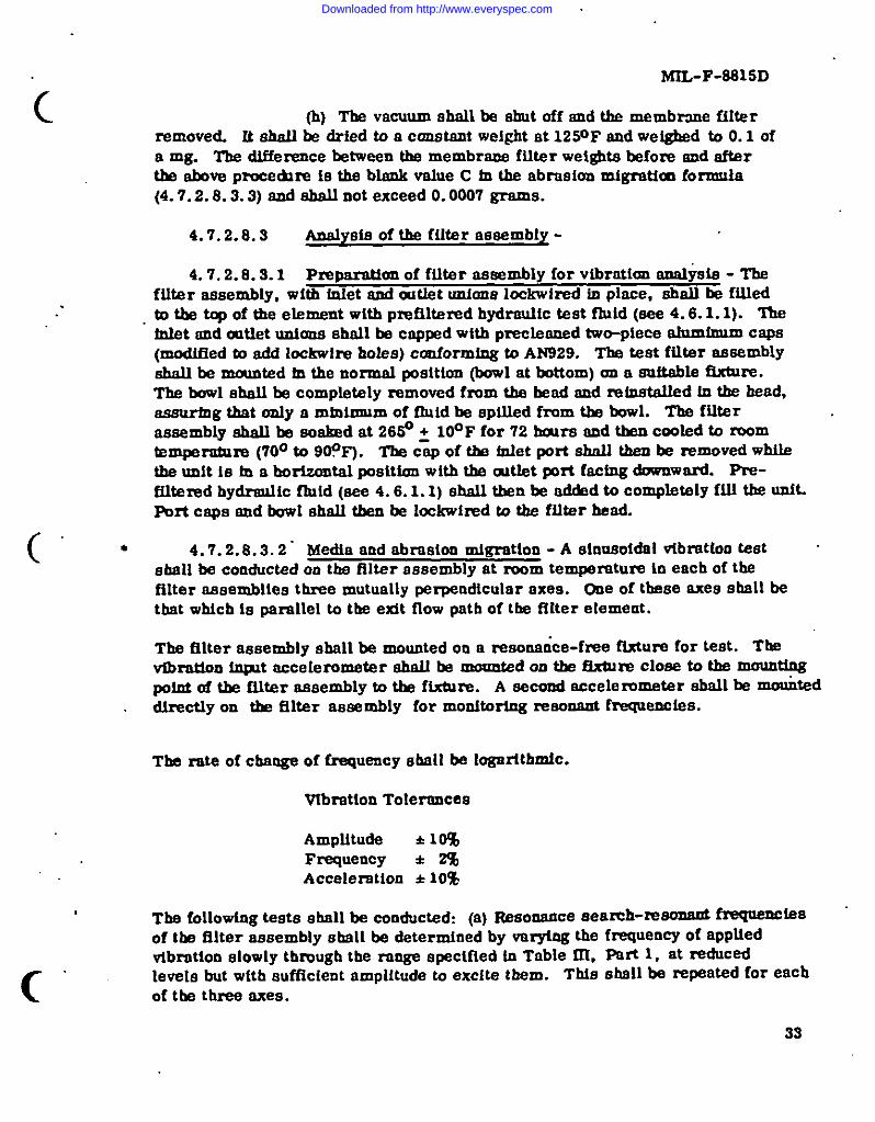
4.7.2 .8.3.1 Pmymmtlen of fflter assembly for vtbrntion aualYsta - Theftlter assembly, with fnlet and out&t unfona lockwired tn place, shell k fffledto the top of the element with pm51tered hydraulic test fluid (see 4.6.1. 1). ‘l%eMet end mtlet untaoe shall be capped withprecteened two-piece alumfmm caps(modified to add bckwIre bofes) conforming to AN829. The test ftlter assemblyshall be mounted fn the normal positton @owl at bottom) an a auiteble ftxture.The bowl shall be completely removed fmm the bsed end mtnetelled fn the haad,aeaurfng that ordy a minimum of fluid be sptlled from tlm bowl. The ftlterassembly shall be eoefmd at 2650 ~ 10°F for 72 bmme end then cooled to momtemperatnm (70° to 90?F). TfM COPof tim tntet pott ehnlf then be removed whifethe unit 1s in a borirontal positton with the atlet prt factng downward. Pre-filtered hydreutic fluid (see 4.6.1.1) shall then be edcbd to completely ftfl the unft.Pmt caps end bowl dudl then be Iockwimd @ the filter head.
(“ “ 4.7.2.8.3.2. Media end abrasion mlgretton - A shmeoldal vtbxatton test .shell be conductsd on the fflter assembly at mom tempemture in each of tbefilter assemblies three mutually perpendicular axes. One of these axes eball bethat wbtch is parallel to the exit flow path of tfm ftker element.
The filter assembly shell be mounted on a resonerice-fme ftxture for test. Tbevlbretinn fnpt accelerometer ebalJ be mounted on ths fixture C1OSSto tbs mountfngpoint of tkm filter assembly to the fixture. A second accelerometer shall be -teddtrectty on the ftlter assembly for monitoring resonant frequencies.
The mte of change of frequency shall be logdthmtc.
Vlbretton Tolerfmces
Amplttude * 10%Frequeocy k 2%Acceleration ● 10!%
The following tests shall be conducted: (a) Resonance eearch-m~ ~~sof the filter assembly s ball be determined by very-log the frequency of appttedvtbmtton slowly tbmugb the range specified tn Table ftI. Feti 1, at reduced
c“levels but wtth auftlcient amplitude to excite them. T~s sbsllbe repeatedfor eachof the three axes,
33
Downloaded from http://www.everyspec.com

....
,
.. .
MIL-F-8815D
@) Resonance dwell - the filter aesembly sbaii be vibratedalong each axis at the four most sewxe msooant fmquenc[es” (determined in thereaonence search) for 30 minutes at each resonance. The vibmtion levels fmdtest times shall be per Table IIi, pert 1.
(c) CYciiog test - the filter eesembly shell ~ vibrated aioogeach axis in accordance with the”teat levels, frequency range end times fromTable~, Parte1 and2. The frequencyofappliedvibrationshaltbe eweptoverthefrequencymnge of5 to2000to5 HZ iogar4thmicatly.The timetoaweepfrom5 to2000to5 Hz shallbe epprox!metely20minutes.Ifa change in the reaonahtfrequency occure during the test, its time of occprence shell be recorded endimmediately the freouency ehall .be adhmted to maintain the peek msonence con-dition. Tti final re~onen_t frequency shail be recorded. -. . .:
TABLE III. Teat Procedure and Time 8cheduie .’”
Vibration Level Frequency” Band, Hz
Rut 1 0.1 inch &tile amplitude ~ ~. 14
log .1A ~:~0.036 inch double amplitude “23 to ’7410.0 g 74 to 2000
Part 2 0.2 loch doubie ampiitude 5 tololog lotols
0.06 inch double ampiitude 18t08120.0 g .81 to 2000
Vibmtiori TUge .%Awduie - (Time Per One Axis)
Pati 1 Number of Reebnences o 1 2 3 4
Total Vibration Time ateach Resonance o *& lb 13 br 2hr
Cycling Time 2iu 1A hr lhr *br o
Part 2 30 minutes cycling per exia -00 reeonaace dweii “
.
..-
.-
....
.-
34
Downloaded from http://www.everyspec.com

.,
MfL-F-8815D
c
(
4.7.2 .8.3.3 Tbe caps dell be removed fmm the port untons end tbe testspectfied 104.7 .2.8.2.1 shell be performed on the filter aesembly. The valueobtefned repreaenta tbe enalysia vnlue A in tbe follmvtng migration formuta:
X= A-C
whelm A = An a l y s i s v a l u e spectfied fn 4.7.2 .8.3.3C = Blank value of bouelng witbmt vibretim apecifted to
4.7.2.8.2.1.X = Mtgrethm analyete value.
Tbe mtgretion emdysie value sfudl not e x c e e d t h e v e t u e s listed tn Teble I of tbee@ceble apecificntton eheet.
“4.7.2 .8.3.4 After compfetim of the wetgbta analysis, the analysis mem-brane from 4.7.2 .8.3.3 shall be exemfned for evtdence of filter media migrationuatng the procechm spectfted fn ARP S98. Them shall be no me~ mlgmktonickmttfteble es cotnIng from the ftlter element medium. Tbe membrane fUter usedfor this teat ebaU be of. contraettng color to the filter etement medtum. A micro-acopa of adequate mnguificnthm shell be used to accurately analyze the meteriafcollected a the membrmke. In the event the abrasion meterlal masks possiblefilter media migretlon, the membrane retatned from the maximum particle paaeedteat (4. 7.2. 5) st@ be scanned for evidence of filter media mtgration. There shallbe no mlgratton i&ntfftable as comfng from tbe filter media.
● 4.7.2.9 Rellef valve operation (M8815/13 element only)
● 4.7.2.9.1 Rellef valve operaUon quellficatkm - Fflter elements havingintegrat dlef vetves, see eppf.fcable specfficatien sheet, shell fE subjected totbe followfng teats. The fil@r element medta abellbeblocked+ thefilterelementtnetdedtna suitablebouatng.By means ofa power~ven punp, presemw shallbe appliedtotbetnletpo~ oftbefilterbmaing,begfnnlngwitha pmaeure of20palad fncnenefng fn tncremente of 10 psi or lees untlt creckfng pxwaeum of the reliefvalve fn the fflter etement befng tested te reackl. At each tnciwnent, tfb? pressureebell be matntalmd conetant for 5 mfxmtaa. At each presaum tncrement; tfmeshall not be coqddemd “fn” or lee)m~ noted until tlm,t@nning of tlm lhird mfnute.TIM leakage rate during the fact 3 mfnutea of each pres.mre fncrement shall be noted.T?ISpressure at wtdch the Ieetmge rate thrmgb tlm reltef valve amounts to 8 cubtccenttmetara (cc) (sPpruxirnately 180 drops) par mimIte shall be ccmsfdered ascrecfdng pmmeure. Crackfng pressure shell occur at SO~ 5 psi. Iadmw up to40 psi shall not exceed 4 cc. (eppmximately 80 @pa) per mhmte. Pfissurs shellbe tncreeeed until mted flow thrcugb the relief VSIVS Is obtafnad. Rated flow ebelloccur et a pressure ditlemntint between inlet end cutlet poate not exceeding 80 PSL
c 35
Downloaded from http://www.everyspec.com

.— - . . ..-
●
✻✌
☛
✚
MIL-J!-5U1511,,
The pressure shell be reducedfn10psidecrements se above until leakage throughthe relief valve doee not exceed the rate of 10 drops per minute. The reeultingpressure shell be considered the relief valve reseattng pressure and e b eU o c c u r a ta pressure of 30 pai or above. ” o
4.7.2.9.2 Relief valve teat (quality conformance) - The filter elementrelief valve shall be installed in a suitable teat block. By means of a powerdriven pump, pressure shall be applled to the inlet port of the tsst block, end .increased to 40 pei. Mter 3 minutes maximum the leakage shall not exceed4 cc/mfn. The pressure shall then be raised to 44.5 psi. After 3 minutesmaxfmum, the leakage aball not. exceed 8 cc/rein. The pressure shell then beraised to 55.5 psi. The leekage “measured shall exceed 8 CC/rein. hc~ege
the flow to 1.5 gpm. The maximum preseun? drop shelf not exceed 80 psi.Reduce the pressure to 30.0 psi and the leakage measured aball not exceed4 cc/mfn. after 3 minutes maximum.
4.8 Preservation, packagm“ g, and markin ~ - Preparation for&live@ shell be examtned for conformance ta eectia 5.
5. PREPARATION FOR DELIVERY
5.1 prese~tiion andpackaging- Preservation alai Pack6ging ‘-shd be in aCCOd$IOCf? withMIL%TD-794, level A only.
5.1.1 Cleaning- Priortopreservation,thefiiterassembliesorelementeshallbe cleanedultrae~cafly(orequivalentmethod)untilfreefromallmetrd chips, grit, diti, and other foreign matter. The ckming methodutilimd shall not have deleterbms effects on any material (e. g., metals, plastics,elastomers, etc. ). Care shafl be taken after cleaning to tneure that neither theassembly or element la contaminated prior to or &rfng preeervetion or packaging.
5.1.2 Preservation (assemblies \ - The filtsr assembly shall beflusbed and filled 80 to 90 percent with hydraulic fluid conforming to MIL-H-6083,prefi.ltered thrcugb a filter assembly conforming to MIL-F-81838(AS), or a filterw itb equivalent efficiency and sealed w itb metal closure e conforming to MIL-C-5501.The fflter assembly shall then be placed withtn a heat-sealed bag confroming toMIL-B-117, TYPS I, CbMS E.,, .
5.1.3 “Preservation (elements ~ - Each element shall be allowed totir dry after cleaning. Air drying shall be accomplished in an atmosphericallycontrolled cleau room or 1aminar flow bench. When dry, the element shall thenbe placed within a heat-sealed bag cenfortig to MIL-B-117, Type L Class E.
,.
36 .$
Downloaded from http://www.everyspec.com

c
(“
c
MU-F-8815D
5.1.4 Pecksgfng -Each ffltorassembly oreletnent Inlte sealed “beg shall be cusMoned end snugly packaged wtthtn a cam or box cnnformtng toPPP-B-566 or PPP-B-676.
5.2 pa- - Packtng shell be tn accordance with MIL-STD-’794,led A, B, or C, es apecifted in the contractor order (see 6. 2). Extertor. con-tefnere abill contain identical quantities end, a~ far as practical, shell have themtntmum cube aad tare caalstent with the pmtectton required.
* 5.2.1 hwel A - Aaaembltea or elements packaged es la 5.1.4, abellbe pecked tn tmug-fttting fiberboard contnlnere conforming to PPP-B-636,weather mstetent. Contetnere shall be closed end sealed aa apactfied lo tbeappcmdtx of PPP-B-636.
● 5.2.2 Lsvel B - Aaaembltea or elements packaged aa to 5.1.4, ehellbe packed in snug-fitting fiberboard contahere cottfomntng to PPP-B-636,domaettc. Contetnera shall be closed and sealed aa apectfied to the appendtx of
“ PPP-~626.
5. s MnrkIng of shipments - Interior packages end exterior abip-pfng containers ebnll be maxiced to nccodance with MIL4TD-129 end, In addition,abelt tnchte the fotlowfn~
M8815/ (insert aleeb number of apectficatton sheet)Month and year of manufactureStyle and size
6. NOTES
6.1 @@@Z&M2- Tbe ftlter eeeembliesendftlterelementscoveredby thteapectficattmaretntendedforuse tnatrcrsftendmisstlehydrauliceyatemscoveredby iWIL-H-5440endMIL-H-25175,andope- withhydr~licfluidconformingtoMIL-H-S606or ML-H-83282 atnomfnnloperettngpreaeureaof3,000paL
● 6.2 . OmkrIng data - Prmmmment documan~ should s p e c i f y t h ef o u ow~
(a) Title, number, end date of this speciftcetion.
(c) Type, cleea,micronratingandstyle(see1.2).
27
Downloaded from http://www.everyspec.com

i,.MIL-F-8815D 7
(d) Applicable Ieiale of preservation, packaging, and ----packing (see section 5).
* 6.2.1 Contract data ‘requiremente - Iteme of deliverable date requtred ,by this speciEcation am ctted In the following peragrepbe:
Paragraph Date.Requirement ApplicableDID
4.5.4 Repoti of fatlure of sampltng teat DI-R-5299A
Such data will be delinred 6s described on approved (numbered) DID’e (DataItemDescription/DDForm 1664)when specifiedonDD Form 1423 (CmitractData Requirements List) and incorporated into & applicable cmtrect.
6.3 @altftcation - With reepect to pmcbmta requiring quallficatton,awarda wW be made caly for mch products as have, prtor to the NDM sat foropati”g of bids, been tested end approved for tncluainn in the applicable ~eltfiedPruducts List whether or not such products have actually been ao lteted by thatdate. l%e attention of the euppliere ia called to ttds requirement, end msmfacturersare urged to arrange to have the producti+ that they propose to offer to tb Fe&ral&wemunant tested for qoaliftcaticm, in order tit ~Y -Y be eligible to be awaadcontractsor orderefortheproductscoveredby thteepecffication.Tba activi~
.
reeponeiblefortheQualiftedProducts Liet ie tlm Navel Air. Syatema Commen d, .4Attn: AIR-530312, Department of the Navy, Wesbingtan, D. C. 20360; however,information pertaining to qualification of producte may be obtained from theCommanding Officer, Naval Air Development Center, (CO& 3021), Warmineter,Penneylvasta 18974.
● 6.4 Change s from “previous issue - The margio of this specificationie maxlmd with an asterisk to fndicate wham cbangea (additione, modtcatione,corrections, &letione) from tk previous ieaue ML- F-6616C were made. Thiswcs done as a convenience only aud the Cievexnment aeeumea no liaQUity whatsoeverfor any insccuraciea in these notations. Blddare aad cootractore are cautioned toevaluate the requirements of this document baaed m the entire content &spectiveof the marginal notations snd relationahtp to the leet prevtoua feeue.
Custodians: Prepartng ectivit~ Navy - ABArmy - AV (Project No. 1650-0326)Navy - ASAir Force -11
Rev@wer activities:Army - MIAir Force -71
38
Downloaded from http://www.everyspec.com

n
6
ICLEAti-UP
FILTER
1-2THERMOMETER
PRESSUREGAGE
h/-
DIFFERENTIAL
PRESSUREGAGE
PRESSUREGAGE
d(M
ust
beby
pasa
edduring
pres
sure
build
upandcollapse
lest)
DUSTVALVE(INLINE
WITHTEST
FILTER)
VALVEA
..
AUTOMATIC
PARTICLE
NOTE:
TOTALSYSTEM
VOLUME
COUNTER
IMUSTNOTEXCEED
TEST
HOUSING
I15GALLONS.
C.&
..
FIGURE1.
~15INCHES
MAX.+
Typtcnlsetup(ordeterrnhrhrg
pressure
buildup
ond
colla
pse
pres
sure
char
acte
ristic
s
1FIAW
..
Downloaded from http://www.everyspec.com

-. .
MIL-F-8815D
150
125
100
75
50
25
0II +75 PSIMAX, BACK +
I i PRESSURE .
~ 15 PERCENT OF CYCLE
TBE CURVE SHOWN ABOVE ISTHE APPROXIMATE PRESSURE-TIMECYCLE DETERMINED TO BE OF PROPER SEVERITY FOR IMPUISETES~G. ALTHOUGH IT IS MANDATORY ONLY THAT PRESSUREPEAK RISES TO 3.S0 PERCENT OF THE OPERATING PRESSURE ATSOME POINT PRIOR TO LEVELING OFF AT RATED PRESSURE, lT ISCONSIDERED HIGHLY DESIRABLE THAT THE P~SURE-TIME CURVEBE CONFINED TO TRE SRADED ABEA INDICATED. ONE VERY DESIR-ABLE BENEFIT TO BE GAINED IN TRIS MANNER IS THAT RESULTS OFTESTS PERFORMED ON DD?FERENT TEST MACRINES WILL BE MORENEARLY COMPARABLE.
DWTIAL BATE OF HLSE PRESSURE APPLICATION TO BE 200,000-200,000 PSI PER SECOND.
-
.
d
FIGURE 2. Impulse curve
40
.
d
Downloaded from http://www.everyspec.com

n
SHUTOFJ
VALVE
ROTOMETER
\
(CFM
)OPTIONAL
AIR
FILTER
.
BLEED
VALVE
/ rSUITABLEMANOMETER
..
..
KNOBFORROTATING
TANK
PROPRIETARY
NT93
EQUIVALENT
FIGuRE
3‘T@cal
schemtlc
diagmm
fornirbubbleteet
Downloaded from http://www.everyspec.com

MIL-F-8815D
. .
VALVEA _CONTAMINANT
INLET
45‘—
‘h+AGITATOR1,750 RPM
CONTAMI- -/NANT MIXINGCHAMBERGIASS ORPLASTIC, 18INCHES LONG3-1/2IliCRESID [
[—
l/2-INCHPIPING <
TEST ELEMENT
J I - AIR PRESSURE GAr e“a AIR PRE9SUREREGULATING
1
3—
VALVE
1CLEANUPFILTER
KAIR FILTER
rm 100 PSI AIRSUPPLY
P- QUICK OPENINGVALVE B
TEST FILTERASSE~LY CONTAINING
FIGURE 4.
42
LPUMP.-
‘lYPical appamtus for determining fll=mefflctency of lina4ype e@oent
d
)
Downloaded from http://www.everyspec.com

--—. . . . . ... . .. .
MIL-F-SS1 SD
c “
~ (-- ~ TO VACWMI --II
< FILTERING FL4SK
FIOURE 5. Diagram of e f f l u e n tf i l t n t l o ns e t u p .
43
Downloaded from http://www.everyspec.com

. .
MIL-F-8815D
nn
r 1 /
6 W
I) 1 1 ~
t w 1 \
1m
11! 111111 111+ m m t- m mo- eam v m
. -----
s
..J
-%
..4
44
Downloaded from http://www.everyspec.com
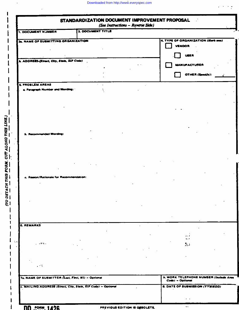
—
I
II
I
I
I
I
1
I
I
I
I
I
III
II
II
;
I
III
I
I
. ..-
STANOARDUATIW 00CWEM IMPROVEMENT PR~L(SeeImou%imo - Rpcr#c w)
~N7 MJMO# R 2.-Mom rrlu .. 71
NAME OP 8UUITTIM0 OaMMl~Ti- 4. TVP9 O* 0ROAN17ATION (- -1
❑ vI”OO”
h —W-d19w
RSMARK9
,.,.,.-
~L j.=..
L MAMEO* SU14MITTERILL inn:. Ml) - Oml- b. WOn K TC UPHON1 NUM8SR (1- Arucd) - OmlOIu
MAILING AoOnEsa (8DWL am.Stints.21? C*J - 0Du091d ● DATE OP SWMlS810N (VVMMDD,
I .
nn FORM IA9C ●nEvtOIJs Sorrlon 18opx.rlu -.
Downloaded from http://www.everyspec.com