filter bank based fractional delay filter implementation
TRANSCRIPT

Filter Bank Based Fractional Delay Filter
Implementation for Widely Accurate Broadband
Steering Vectors
Mohamed A. Alrmah and Stephan Weiss
Department of Electronic & Electrical Engineering, University of Strathclyde,Glasgow,Scotland, UK
mohamed.alrmah;[email protected]
Abstract—Applications such as broadband angle of arrivalestimation require the implementation of accurate broadbandsteering vectors, which generally rely on fractional delay filterdesigns. These designs commonly exhibit a rapidly decreasingperformance as the Nyquist rate is approached. To overcomethis, we propose a filter bank based approach, where standardfractional delay filters operate on a series of frequency-shiftedoversampled subband signals, such that they appear in thefilter’s lowpass region. Simulations demonstrate the appeal ofthis approach.
I. INTRODUCTION
In broadband sensor array signal processing, time delays
that arise from wave fronts propagating across the array at
finite speed require to be addressed as lags rather than be
represented by phase shifts as in the narrowband case. Nor-
mally non-integer multiples of the sampling period, fractional
delay filters need to be employed [1], [2]. Since sensor array
applications potentially operate across several octaves, the
accuracy of such fractional delays is crucial to the precision
of broadband angle of arrival estimation or the performance
of any other subsequent processing [3].
To implement fractional delays, a sinc function can be
appropriately sampled [4], [5] and restricted to finite support
by truncation. This leads to discrete prolate spheroidal se-
quences [6], which suffer from a ripple in the group delay and
a degradation in performance that increases with frequency.
This restricted accuracy of fractional delay filters [5] often
limits their application to lowpass-type signals.
In order to enhance the fractional delay filters’ performance,
tapered instead of rectangular windows have been proposed
to truncate the sinc function [4], [7], leading to a lower
group delay ripple. A polynomial approximation approach was
introduced by Farrow [8], which, at a modest filter order, pro-
vides relatively good accuracy. However, both Farrow structure
and windowed sinc still perform best a low frequencies,
with a significant performance degradation towards higher
frequencies.
Subbands created by decimated filter banks have previously
been used in the context of fractional delays, since decimation
can shorten long impulse responses such as sinc functions [9].
Recognising that recent fractional delay approaches are fairly
accurate at low frequencies and only degrade towards higher
frequencies, this paper proposes to modulate undecimated
subbands as created by filter banks to acquire lowpass charac-
teristics. After applying fractional delay filters in the lowpass
domain, a frequency shift to the original band is performed,
and a synthesis filter bank operation completes the proposed
accurate broadband fractional delay filter approach.
Below, Sec. II motivates the requirement of highly accurate
fractional delay filters by reviewing the construction of broad-
band steering vectors. Sec. III reviews different approaches
for designing fractional delay filters followed by the proposed
filter bank approach outlined in Sec. IV. Simulation results are
presented in Sec. V to compare and characterise the accuracy
of the proposed approach to various benchmarks. Conclusions
are drawn in Sec. VI.
II. BROADBAND STEERING VECTORS
An M-element array of omnidirectional sensors located at
positions rm, m = 1 . . .M collects a signal vector x(t) ∈ CM ,
with the continuous time variable t. If a far field source
illuminates the array such that the signal at the origin r = 0
is s(t) and we neglect attenuation, then
x(t) =
s(t −T1)s(t −T2)
...
s(t −TM)
=
δ (t −T1)δ (t −T2)
...
δ (t −TM)
∗ s(t) (1)
with ∗ denoting convolution, and delays Tm = 1ckTrm, m =
1 . . .M, where k is the normal vector of the source’s wave
front, and k/c is known as the slowness vector of the source.
Sampling x(t) with a period Ts yields x[n], with discrete
time index n such that t = nTs. Under the assumption of a
perfectly bandlimited signal s(t), the interpolator underlying
the sampling process is a sinc function. With
x[n] =
δ [n− τ1]δ [n− τ2]
...
δ [n− τM]
∗ s[n] = a[n]∗ s[n] , (2)
and normalised delays τm = Tm/Ts, the ideal fractional delays
δ [n− τm],
δ [n− τ] =
sin(π(n−τ))π(n−τ) , n 6= τ
1 , n = τ(3)
2013 5th IEEE International Workshop on Computational Advances in Multi-Sensor Adaptive Processing (CAMSAP)
978-1-4673-3146-3/13/$31.00 ©2013IEEE 332
are now sinc functions which not necessarily remain sampled
in the sinc’s zero crossing, and therefore generally possess
infinite support. The quantity a[n] in (2) is referred to as broad-
band steering vector, and consists of a number of different
fractional delays of the type in (3).
A signal model for a scenario with L independent far field
broadband sources sl [n], l = 1 . . .L, each characterised by a
broadband steering vector al [n], therefore becomes
x[n] =L
∑l=1
∞
∑ν=0
al [ν]sl [n−ν] + v[n] , (4)
with v[n] representing spatially and temporally uncorrelated
noise with covariance E
v[n]vH[n]
= σ2v I. To capture infor-
mation contained in the data vector x[n] requires a space-
time covariance matrix R[ν] = E
x[n]xH[n−ν]
with lag
parameter ν . Its Fourier pair, the cross-spectral density matrix
R(z) = ∑ν R[ν]z−ν or short R[ν] —• R(z),
R(z) =L
∑l=1
a(z)aH(z−1)Rl(z)+σ2v I (5)
with Rl(z) the power spectral density of the lth source, forms
a polynomial matrix.
A number of broadband array methods directly utilise the
broadband steering vector. For example, in [3] broadband
steering vectors are used to presteer array data. The parametric
covariance matrix approach in [2], [10] presteers the data prior
to scanning for maximised eigenvalues in the resulting covari-
ance matrix. For the polynomial MUSIC algorithm in [1], a
polynomial eigenvalue decomposition [11] of the space-time
covariance matrix in (5) identifies the noise-only subspace,
which can then be scanned using broadband steering vectors,
in analogy to the narrowband MUSIC algorithm [12]. Thus,
the accuracy of the broadband steering vector implementation
impacts crucially on all of these applications.
III. FRACTIONAL DELAY FILTERS
With the definition of the ideal fractional delay and an
error metric defined in Sec. III-A, this section reviews various
implementation methods for fractional delay filters, including
windowed sinc functions in Sec. III-B and the Farrow struc-
ture [8] in Sec. III-C.
A. Ideal Delay and Performance Metric
Based on the definition of the ideal fractional delay in (3),
fideal[n] = δ [n− τ] , (6)
and the Fourier pair δ [n] —• 1, the Fourier transform of the
fractional delay yields
Fideal(ejΩ) = 1 · e− jΩτ (7)
with a group delay γideal = τ . Using this ideal delay, an error
metric for an arbitrary fractional delay filter approximation
f [n] can be defined as
See(ejΩ) =
∣
∣
∣Fideal(e
jΩ)−F(e jΩ)∣
∣
∣
2
, (8)
with F(e jΩ) •— f [n], such that See(ejΩ) is a quadratic error
metric for the approximation of fideal[n] by f [n].
+×
τ
X(z)
CM (z) C1(z)
×
τ
×
τ
. . .
Y (z)
C0(z)
+
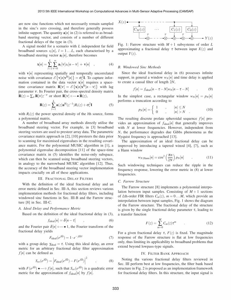
Fig. 1: Farrow structure with M + 1 subsystems of order L
approximating a fractional delay τ between input X(z) and
output Y (z).
B. Windowed Sinc Methods
Since the ideal fractional delay in (6) possesses infinite
support, in general a window wN [n] and time delay is applied
to create a causal filter of length 2N,
f [n] = fideal[n− τ −N]wN [n− τ −N] . (9)
In the simplest case, a rectangular window wN [n] = pN [n]performs a truncation according to
pN [n] =
1 , |n| ≤ N
0 , |n|> N .(10)
The resulting discrete prolate spheroidal sequence f [n] pro-
vides an approximation of fideal[n] that generally improves
with N at lower frequencies. However, independent from
N, the performance degrades due Gibbs phenomena as the
Nyquist frequency is approached [13].
The approximation of an ideal fractional delay can be
improved by introducing a tapered winod [4], [7], such as
a Hann window
wN,Hann[n] = cos2( πn
2N
)
pN [n] . (11)
Such windowing techniques can reduce the ripple in the
frequency response, lowering the error metric in (8) at lower
frequencies.
C. Farrow Structure
The Farrow structure [8] implements a polynomial interpo-
lation between input samples. Consisting of M + 1 sections
of Lth-order FIR filters Cm(z), m = 0 . . .M, which provide an
interpolation between input samples, Fig. 1 shows the diagram
of the Farrow structure. The fractional delay of the structure
is given by the single fractional delay parameter τ , leading to
a transfer function
F(z) =M
∑m=0
Cm(z)τm . (12)
For a given fractional delay τ , F(z) is fixed. The magnitude
response of the Farrow structure is flat at low frequencies
only, thus limiting its applicability to broadband problems that
extend beyond lowpass-type signals.
IV. FILTER BANK APPROACH
Noting tha various fractional delay filters reviewed in
Sec. III perform best at low frequencies, the filter bank based
structure in Fig. 2 is proposed as an implementation framework
for fractional delay filters. In this structure, the input signal is
2013 5th IEEE International Workshop on Computational Advances in Multi-Sensor Adaptive Processing (CAMSAP)
333
x[n] y[n]+
hK [n]
h2[n]
h1[n]
...
×
×
ejΩ1n
ejΩ2n
ejΩKn
...
× f [n]
f [n]
f [n]
...
e−jΩ1n
e−jΩ2n
e−jΩKn
...
×
×
×
g1[n]
g2[n]
gK [n]
...
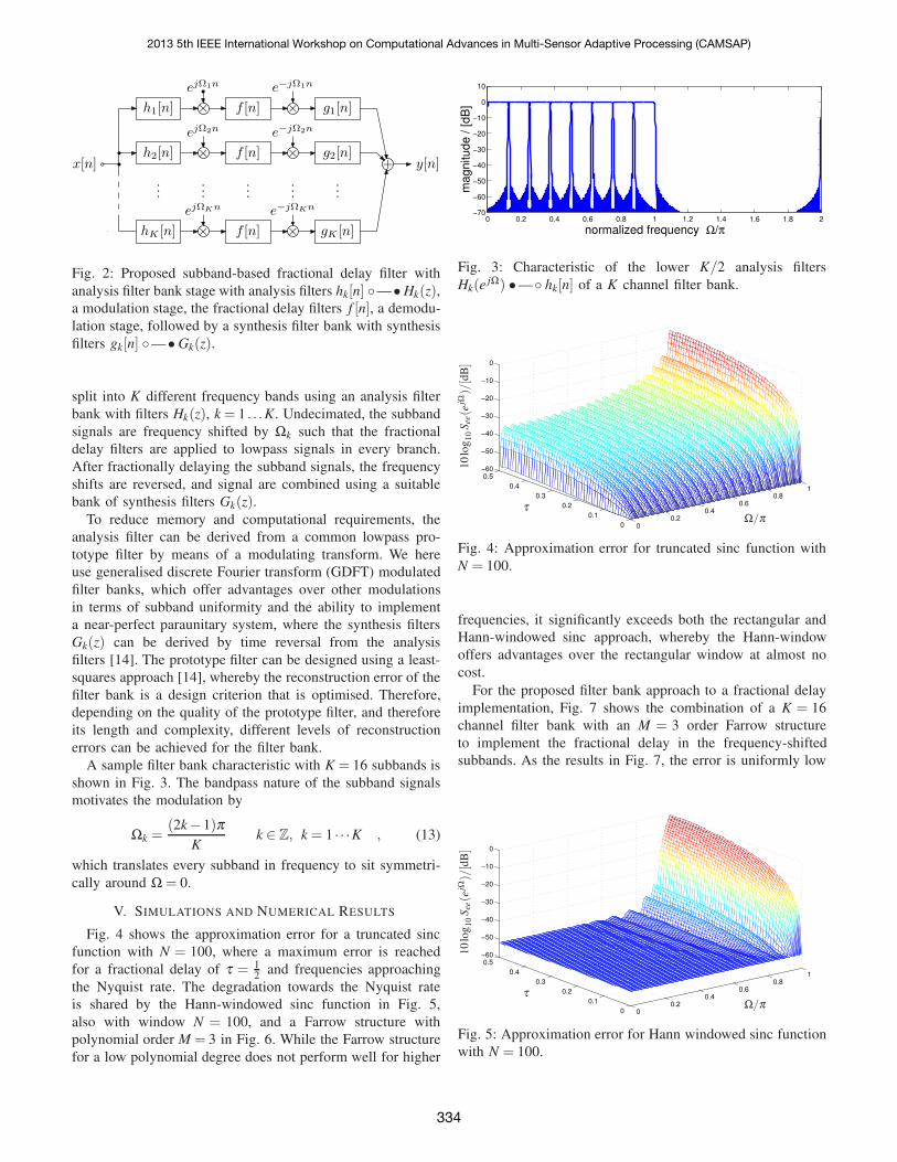
Fig. 2: Proposed subband-based fractional delay filter with
analysis filter bank stage with analysis filters hk[n] —• Hk(z),a modulation stage, the fractional delay filters f [n], a demodu-
lation stage, followed by a synthesis filter bank with synthesis
filters gk[n] —• Gk(z).
split into K different frequency bands using an analysis filter
bank with filters Hk(z), k = 1 . . .K. Undecimated, the subband
signals are frequency shifted by Ωk such that the fractional
delay filters are applied to lowpass signals in every branch.
After fractionally delaying the subband signals, the frequency
shifts are reversed, and signal are combined using a suitable
bank of synthesis filters Gk(z).To reduce memory and computational requirements, the
analysis filter can be derived from a common lowpass pro-
totype filter by means of a modulating transform. We here
use generalised discrete Fourier transform (GDFT) modulated
filter banks, which offer advantages over other modulations
in terms of subband uniformity and the ability to implement
a near-perfect paraunitary system, where the synthesis filters
Gk(z) can be derived by time reversal from the analysis
filters [14]. The prototype filter can be designed using a least-
squares approach [14], whereby the reconstruction error of the
filter bank is a design criterion that is optimised. Therefore,
depending on the quality of the prototype filter, and therefore
its length and complexity, different levels of reconstruction
errors can be achieved for the filter bank.
A sample filter bank characteristic with K = 16 subbands is
shown in Fig. 3. The bandpass nature of the subband signals
motivates the modulation by
Ωk =(2k− 1)π
Kk ∈ Z, k = 1 · · ·K , (13)
which translates every subband in frequency to sit symmetri-
cally around Ω = 0.
V. SIMULATIONS AND NUMERICAL RESULTS
Fig. 4 shows the approximation error for a truncated sinc
function with N = 100, where a maximum error is reached
for a fractional delay of τ = 12
and frequencies approaching
the Nyquist rate. The degradation towards the Nyquist rate
is shared by the Hann-windowed sinc function in Fig. 5,
also with window N = 100, and a Farrow structure with
polynomial order M = 3 in Fig. 6. While the Farrow structure
for a low polynomial degree does not perform well for higher
0 0.2 0.4 0.6 0.8 1 1.2 1.4 1.6 1.8 2−70
−60
−50
−40
−30
−20
−10
0
10
normalized frequency Ω/π
ma
gn
itu
de
/ [
dB
]
Fig. 3: Characteristic of the lower K/2 analysis filters
Hk(ejΩ) •— hk[n] of a K channel filter bank.
00.2
0.40.6
0.81
0
0.1
0.2
0.3
0.4
0.5−60
−50
−40
−30
−20
−10
0
τΩ/π
10
log
10
See(e
jΩ)/[d
B]
Fig. 4: Approximation error for truncated sinc function with
N = 100.
frequencies, it significantly exceeds both the rectangular and
Hann-windowed sinc approach, whereby the Hann-window
offers advantages over the rectangular window at almost no
cost.
For the proposed filter bank approach to a fractional delay
implementation, Fig. 7 shows the combination of a K = 16
channel filter bank with an M = 3 order Farrow structure
to implement the fractional delay in the frequency-shifted
subbands. As the results in Fig. 7, the error is uniformly low
00.2
0.40.6
0.81
0
0.1
0.2
0.3
0.4
0.5−60
−50
−40
−30
−20
−10
0
τΩ/π
10
log
10
See(e
jΩ)/[d
B]
Fig. 5: Approximation error for Hann windowed sinc function
with N = 100.
2013 5th IEEE International Workshop on Computational Advances in Multi-Sensor Adaptive Processing (CAMSAP)
334

0
0.5
1
1.5
2
0
0.1
0.2
0.3
0.4
0.5−140
−120
−100
−80
−60
−40
−20
0
τΩ/π
10
log
10
See(e
jΩ)/[d
B]
Fig. 6: Approximation error for Farrow structure for M = 3.
with a maximum error See(ejΩ) of -55dB across all frequencies
Ω and fractional delays τ . Here, See(ejΩ) consists of two
contributions — (i) an error due to inaccuracies on the Farrow
structure, and (ii) a reconstruction error within the filter bank.
Here, with a reconstruction error of -55dB [14], the latter
dominates. This is underlined by the same error of -55dB
that is obtained in combination with a Hann windowed sinc
function, and a Farrow structure of order M = 9. In contrast,
embedding the sinc function characterised in Fig. 4 into the
subbands yields an approximation error of approximately -
37dB; i.e. for this case, the fractional delay filter is sufficiently
crude to dominate the overall error of the system.
Since an undecimated filter bank is costly in terms of
computations, the filter bank design can be selected such that
it is just sufficiently good to match the desired approximation
error for the fractional delay filter f [n]. This ensures that the
system is not over-designed, and that the cost of the filter bank
can be kept as low as possible.
VI. CONCLUSIONS
Accurate broadband steering vector requirements for appli-
cations such as broadband angle of arrival estimation have
motivated the implementation of fractional delay filters that
can approach the ideal fractional delay over a large bandwidth.
Since state-of-the-art fractional delays such as windowed sinc
and Farrow filters perform best at low frequencies only,
we have combined these filters with a modified filter bank,
whereby undecimated subband signals are modulated such that
only a small lowpass region is active in each subband. The
subband signals can then be accurately delayed by any of the
established methods.
As demonstrated in simulations, uniform accuracy can be
achieved across the entire bandwidth, whereby the approxima-
tion error w.r.t. an ideal delay is either limited by the fractional
delay filter or the reconstruction error of the filter bank.
τΩ/π
10
log
10
See(e
jΩ)/[d
B]
Fig. 7: Approximation error for filter bank approach with with
K = 16, and an L = 3 order Farrow filter as subband fractional
delay f [n].
REFERENCES
[1] M. Alrmah, S. Weiss, and S. Lambotharan, “An extension of the musicalgorithm to broadband scenarios using polynomial eigenvalue decom-position,” in 19th European Signal Processing Conference, Barcelona,Spain, August 2011, pp. 629–633.
[2] J. Dmochowski, J. Benesty, and S. Affes, “Direction of arrival estimationusing the parameterized spatial correlation matrix,” IEEE Transactions
on Audio, Speech, and Language Processing, vol. 15, no. 4, pp. 1327–1339, May 2007.
[3] P. Murphy, A. Krukowski, and A. Tarczynski, “An efficient fractionalsample delayer for digital beam steering,” in IEEE International Con-
ference on Acoustics, Speech, and Signal Processing, vol. 3, Munich,Germany, April 1997, pp. 2245–2248.
[4] A. Yardim, G. Cain, and P. Henry, “Optimal two-term offset windowingfor fractional delay,” Electronics Letters, vol. 32, no. 6, pp. 526–527,March 1996.
[5] T. I. Laakso, V. Valimaki, M. Karjalainen, and U. K. Laine, “Splittingthe Unit Delay,” IEEE Signal Processing Magazine, vol. 13, no. 1, pp.30–60, January 1996.
[6] A. Papoulis, Signal Analysis. New York: McGraw-Hill, 1984.[7] J. Selva, “An efficient structure for the design of variable fractional delay
filters based on the windowing method,” IEEE Transactions on Signal
Processing, vol. 56, no. 8, pp. 3770–3775, August 2008.[8] C. W. Farrow, “A continuously variable digital delay element,” in
IEEE International Symposium on Circuits and Systems, vol. 3, Espoo,FInland, June 1988, pp. 2641–2645.
[9] S. Weiss, S. R. Dooley, R. W. Stewart, and A. K. Nandi, “Adap-tive Equalisation in Oversampled Subbands,” IEE Electronics Letters,vol. 34, no. 15, pp. 1452–1453, July 1998.
[10] M. Souden, J. Benesty, and S. Affes, “Broadband source localiza-tion from an eigenanalysis perspective,” IEEE Transactions on Audio,
Speech, and Language Processing, vol. 18, no. 6, pp. 1575–1587, August2010.
[11] J. G. McWhirter, P. D. Baxter, T. Cooper, S. Redif, and J. Foster,“An EVD Algorithm for Para-Hermitian Polynomial Matrices,” IEEE
Transactions on Signal Processing, vol. 55, no. 5, pp. 2158–2169, May2007.
[12] R. O. Schmidt, “Multiple emitter location and signal parameter estima-tion,” IEEE Transactions on Antennas and Propagation, vol. 34, no. 3,pp. 276–280, March 1986.
[13] M. Sac and M. Blok, “Gain deficit effect in the fractional delay filterdesign by the window method,” in Proc. SPIE Photonics Applications
in Astronomy, Communications, Industry, and High-Energy Physics
Experiments, vol. 75021G, August 2009, pp. 1–6.[14] M. Harteneck, S. Weiss, and R. Stewart, “Design of near perfect
reconstruction oversampled filter banks for subband adaptive filters,”IEEE Transactions on Circuits and Systems II: Analog and Digital
Signal Processing, vol. 46, no. 8, pp. 1081–1085, August 1999.
2013 5th IEEE International Workshop on Computational Advances in Multi-Sensor Adaptive Processing (CAMSAP)
335