filtering a switched power supply
TRANSCRIPT

Filtering a Switched Power Supply | Power Circuits
Power CircuitsPresenting the many facets of modern power electronics engineering.
Filtering a Switched Power Supply
February 23, 2015 admin Leave a comment
As seen in the previous post, a simple switch or diode rectified output is still not a clean DC signal. The waveform contains AC components on top of the DC
offset. The simplest methods for smoothing this output involve filtering through the use of passive storage elements such as capacitors or inductors. In
essence, these components tend to smooth the output by storing energy during peaks in the waveform, and giving that energy back at low points in the
waveform. Though this may seem straight forward, some interesting and unexpected effects can spring up as we will see.
An example is shown below. In this circuit, the left switch is turned on to store energy in the inductor. The right switch sends energy from the inductor into the
load. The inductor mediates energy transfer through the system, and adds flexibility to the converter. Let us consider a possible way of operating this circuit.
The switches in this circuit are controlled to operate in alternation: when the left switch is on, the right switch is off, and so on. What does the circuit do if each http://powercircuits.net/filtering-switched-power-supply/ (1 of 5) [4/16/2015 7:01:34 PM]
Filtering a Switched Power Supply | Power Circuits
switch operates half time? The inductor and capacitor have large values.
When the left switch is on, the source voltage appears across the inductor. If this circuit is to be a useful converter, we want the inductor to receive energy
from the source and deliver it to the load without loss. Over time, this means that energy should not be allowed to build up in the inductor (it should flow through
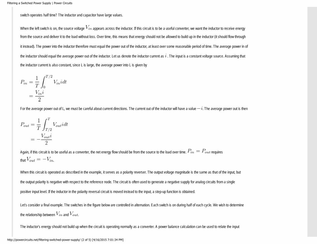
it instead). The power into the inductor therefore must equal the power out of the inductor, at least over some reasonable period of time. The average power in of
the inductor should equal the average power out of the inductor. Let us denote the inductor current as . The input is a constant voltage source. Assuming that
the inductor current is also constant, since L is large, the average power into L is given by
For the average power out of L, we must be careful about current directions. The current out of the inductor will have a value . The average power out is then
Again, if this circuit is to be useful as a converter, the net energy flow should be from the source to the load over time. requires
that .
When this circuit is operated as described in the example, it serves as a polarity reverser. The output voltage magnitude is the same as that of the input, but
the output polarity is negative with respect to the reference node. The circuit is often used to generate a negative supply for analog circuits from a single
positive input level. If the inductor in the polarity reversal circuit is moved instead to the input, a step-up function is obtained.
Let’s consider a final example. The switches in the figure below are controlled in alternation. Each switch is on during half of each cycle. We wish to determine
the relationship between and .
The inductor’s energy should not build up when the circuit is operating normally as a converter. A power balance calculation can be used to relate the input
http://powercircuits.net/filtering-switched-power-supply/ (2 of 5) [4/16/2015 7:01:34 PM]

Filtering a Switched Power Supply | Power Circuits
and output voltages. Again let be the inductor current. When the left switch is on, power is injected into the inductor. The average value of the power input into
the inductor is again
Power leaves the inductor when the right switch is on. Again we need to be careful of polarities and signs. Remember that current should be set negative
to represent output power. This time, the result is
Applying the power balance restriction, we equate the input and output power,
Energy transfer switching circuit used in the second example.
Clearly, the output voltage is indeed double the input. Many seasoned engineers find the DC-DC step-up function we just
walked through to be surprising. Yet, this is just one simple example of such action. Others (including circuits related to this
circuits) are used in systems from CRT electron guns to spark ignitions for automobiles.
The circuits we have just analyzed have very few components. A commercial step-up circuit is shown below. The left switch
is implemented as four power MOSFETs (metal oxide semiconductor field effect transistor) in parallel, while the right switch
is a diode. This circuit actually takes in an AC supply, then rectifies it and boosts up the result. It can supply up to 3000 W at
400 V DC from a 240 V AC source. There are extra components for control functions, but the power electronic heart is the polarity reversal circuit identical to
the examples above.
http://powercircuits.net/filtering-switched-power-supply/ (3 of 5) [4/16/2015 7:01:34 PM]

Filtering a Switched Power Supply | Power Circuits
The history of power electronics has tended to flow like these examples: a circuit with a particular conversion function is discovered, analyzed, and applied. As
the circuit moves from a simple laboratory test to a complete commercial product, control and protection functions are added. The power portion of the
circuit remains close to the original idea. The natural question arises as to whether a systematic approach to conversion is possible. Can you start with a
desired function and design an appropriate converter? Are there underlying principles that apply to all design and analysis? Where do all these control
functions come from and what do they try to accomplish? How do the circuits Work? In future posts, we will begin to see how the various aspects of energy
flow manipulation, sensing and control, the energy source, and the load fit together in a complete design. The goal is a systematic treatment of power
electronics. Keep in mind that while many of the circuits look deceptively simple, all are nonlinear systems with unusual behavior.
Share this:
●
Background Goals and MethodsLeave a Reply
Categories
● Background● Goals and Methods● History● Switches● Waveforms
http://powercircuits.net/filtering-switched-power-supply/ (4 of 5) [4/16/2015 7:01:34 PM]
Filtering a Switched Power Supply | Power Circuits
Recent Posts
● Overview of Switching Devices● Review of Fourier Series● Characteristics of Power Semiconductor Devices● Kirchhoff’s Voltage and Current Laws● Introduction to Switches
Archives
● April 2015● March 2015● February 2015● January 2015
Subscribe to Blog via Email
Enter your email address to subscribe to this blog and receive notifications of new posts by email.
Email Address
Pages
● Contact Us● Privacy Policy
http://powercircuits.net/filtering-switched-power-supply/ (5 of 5) [4/16/2015 7:01:34 PM]