filtration hydrocyclone sand separatorsirrigation-mart.com/customer/irrmar/specpages... · 2 •...
TRANSCRIPT
OPERATION, INSTALLATION & MAINTENANCE GUIDE
HYDROCYCLONESAND SEPARATORS
FILTRATION
HYDROCYCLONE &SEDIMENTATION TANK
2 • HYDROCYCLONE SAND SEPARATORS
DESCRIPTION
A Hydrocyclone separates sand and other solid matter from water with very little head loss and 90% or better efficiency. There is no head loss build up and no clogging when the solids are separated. Hydrocyclones are easy to operate and maintain, and have no moving parts or screens.
Versatility in system configurations and ease of installation are some of its great advantages.
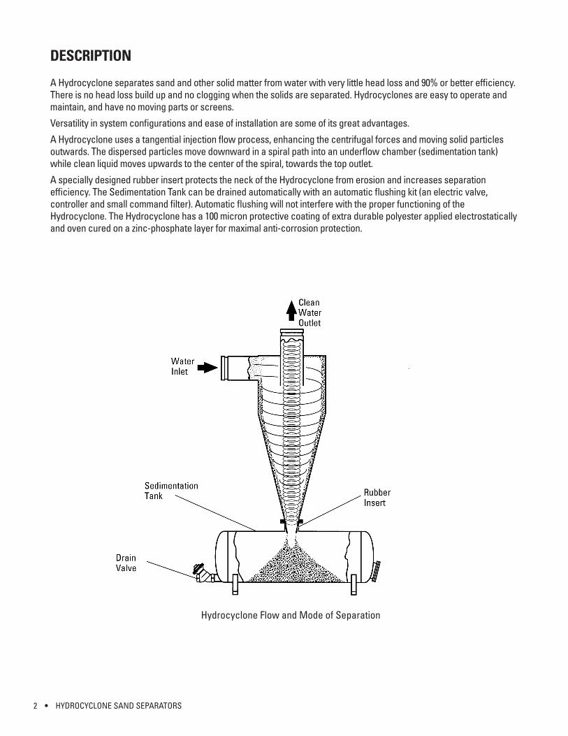
A Hydrocyclone uses a tangential injection flow process, enhancing the centrifugal forces and moving solid particles outwards. The dispersed particles move downward in a spiral path into an underflow chamber (sedimentation tank) while clean liquid moves upwards to the center of the spiral, towards the top outlet.
A specially designed rubber insert protects the neck of the Hydrocyclone from erosion and increases separation efficiency. The Sedimentation Tank can be drained automatically with an automatic flushing kit (an electric valve, controller and small command filter). Automatic flushing will not interfere with the proper functioning of the Hydrocyclone. The Hydrocyclone has a 100 micron protective coating of extra durable polyester applied electrostatically and oven cured on a zinc-phosphate layer for maximal anti-corrosion protection.
Hydrocyclone Flow and Mode of Separation
HYDROCYCLONE SAND SEPARATORS • 3
SPECIFICATIONS
As a rule, the separation efficiency improves as the Hydrocyclone diameter decreases and the head loss increases. Miniature Hydrocyclones may be used for easy sampling of liquids, for determining filter (including larger Hydrocyclones) operation and efficiency and for testing the feasibility of operation for the problem at hand.
Each filter is designed and manufactured in order to achieve the highest standard of quality and finish.
• Recommended head loss for effective operation: 3-8 psi• Maximum recommended working pressure: 120 psi• Maximum pressure: 150 psi• Water inlet and outlet: horizontal and vertical• Inserts: standard on all sizes except 3” and 4”• Protective coating: polyester on zinc-phosphate layer• Pressure relief valve: must be inserted before the filtering installation if pressure is not controlled• Available sizes: 3”, 4”, 6”, 8”, 12”, 16”, 20”, 24” and 30”• End connections: Thread (TH), Flange (FL), Groove (GR)• Sedimentation Tank connections:
− Thread: 3” and 4” sizes− Flange: 12”, 16”, 20”, 24” and 30” sizes− Groove: 6” and 8” sizes
OPERATION
Based on the centrifuge principle, the particles are spun against the outside wall of the Hydrocyclone and gravitate towards the bottom into the Sedimentation Tank. The velocity at which the water flows through the Hydrocyclone determines the efficiency at which the particles are separated from the water.
• Normal working conditions are achieved when headloss on the Hydrocyclone is not less than 3 psi with arecommended range of 3-8 psi.
− A headloss of less than 3 psi will reduce the separation efficiency and a headloss of more than 8 psi might induce increased erosion.
• The Hydrocyclone is designed for a maximum recommended working pressure of 120 psi and should not exceed150 psi.
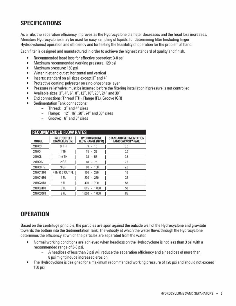
RECOMMENDED FLOW RATES
MODEL24HC324HC424HC624HC8V24HC8HV24HC12F624HC16F624HC20F824HC24F824HC30F8
INLET/OUTLETDIAMETERS (IN)
¾ TH1 TH
1½ TH2 GR3 GR
4 IN & 3 OUT FL4 FL6 FL6 FL8 FL
HYDROCYCLONEFLOW RANGE (GPM)
9 - 1515 - 3333 - 5348 - 7580 - 150
150 - 230230 - 360430 - 700 615 - 1,000
1,000 - 1,600
STANDARD SEDIMENTATIONTANK CAPACITY (GAL)
0.50.52.62.62.61632585885
4 • HYDROCYCLONE SAND SEPARATORS
INSTALLATION
• Install and connect the Hydrocyclone vertically with the Sedimentation Tank underneath the Hydrocyclone.• Special attention must be given to the correct flow direction: horizontal inlet and top vertical outlet are clearly
marked by arrows.• Install the manual ball valve to the flush port of the Sedimentation Tank.• Check that the actual flow rate through the Hydrocyclone is within the recommended range. Inadequate flow
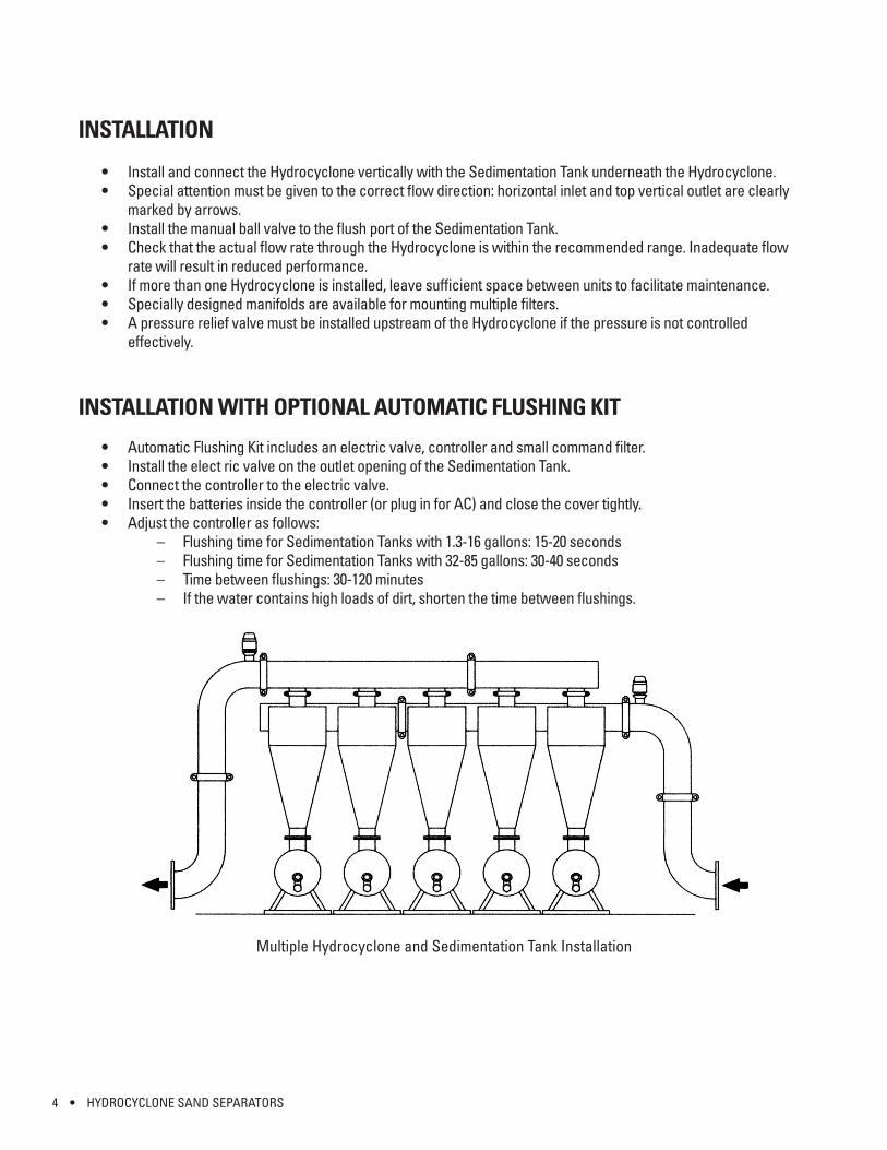
rate will result in reduced performance.• If more than one Hydrocyclone is installed, leave sufficient space between units to facilitate maintenance.• Specially designed manifolds are available for mounting multiple filters.• A pressure relief valve must be installed upstream of the Hydrocyclone if the pressure is not controlled
effectively.
INSTALLATION WITH OPTIONAL AUTOMATIC FLUSHING KIT
• Automatic Flushing Kit includes an electric valve, controller and small command filter.• Install the elect ric valve on the outlet opening of the Sedimentation Tank.• Connect the controller to the electric valve.• Insert the batteries inside the controller (or plug in for AC) and close the cover tightly.• Adjust the controller as follows:
– Flushing time for Sedimentation Tanks with 1.3-16 gallons: 15-20 seconds– Flushing time for Sedimentation Tanks with 32-85 gallons: 30-40 seconds– Time between flushings: 30-120 minutes– If the water contains high loads of dirt, shorten the time between flushings.
Multiple Hydrocyclone and Sedimentation Tank Installation
HYDROCYCLONE SAND SEPARATORS • 5
SEDIMENTATION TANK FLUSHING
• The Sedimentation Tank can be flushed manually or automatically with an irrigation controller or computer at periodic intervals.
• When a manual valve is installed, drain the Sedimentation Tank at periodic intervals according to the recommendations.
• The Sedimentation Tank should be drained when it is 1⁄3 full.• Do not let the Sedimentation Tank get filled more than ½ of its volume, otherwise the sand will not flush properly.
As a result, the sand will spin, have no place to drain, and cause pin holes in the neck of the Hydrocyclone.
SEDIMENTATION TANK PERIODIC CLEANING
• Check that the rubber insert is not worn or damaged and replace if necessary. When separating sand, the rubber insert may need to be replaced every 2-3 years. When separating silt, the rubber insert may need to be replaced every year.
• Close the valve at the inlet of the Hydrocyclone.• Open the drain valve located at the bottom of the Sedimentation Tank to release pressure and drain.• Take off the cover.• Remove all the sediments collected in the Sedimentation Tank.• Thoroughly rinse the inside of the empty Sedimentation Tank.• Replace the cover on the Sedimentation Tank so that the cover gasket fits over it.• Mount tightening bracket and tightening handle properly.
WARNING: Do not tighten or open cover during operation or under pressure.
MAINTENANCE
• Apply a layer of grease to handle threads once a year. • Immediately repair any damage to the tank’s protective coating.
6 • HYDROCYCLONE SAND SEPARATORS
20 30 40 50 100 200 500 1000 2000 5 300 10
15
8 6 5 4 3
2
10
HEADLOSS
Gallons per Minute
Pres
sure
(psi)
Reco
mm
ende
d Ra
nge
3
4
6
8
8H
12
16
20
24
30
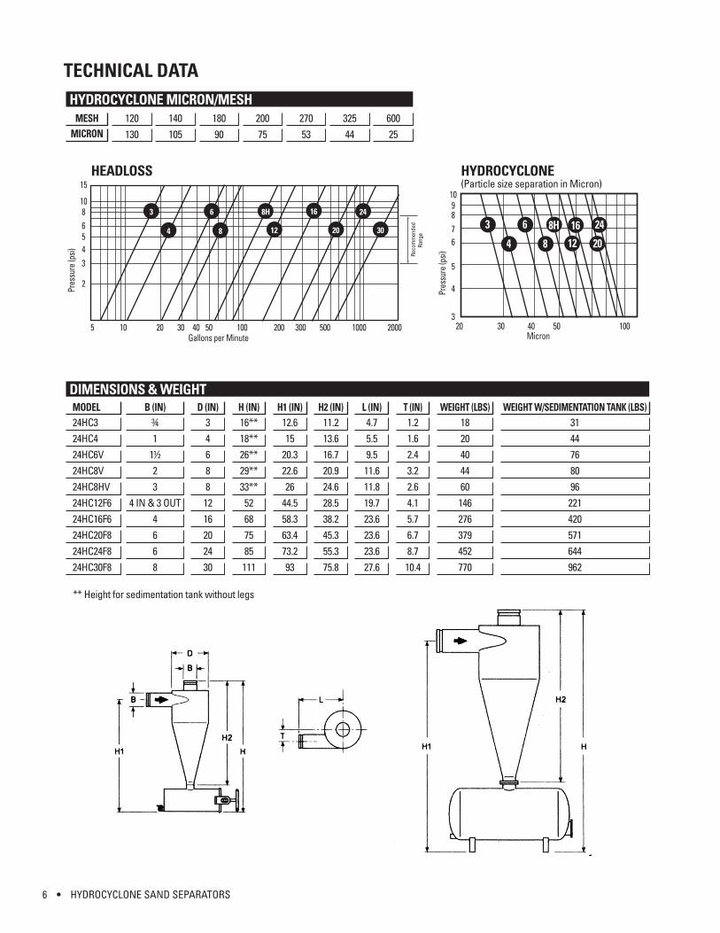
HYDROCYCLONE MICRON/MESHMESH
MICRON120130
140105
18090
20075
27053
32544
60025
HYDROCYCLONE (Particle size separation in Micron)
20 30 40 50 100
9 8 7 6
5
4
3
10
Pres
sure
(psi)
3 6 8H
12 20 4 8
16 24
Micron
TECHNICAL DATA
DIMENSIONS & WEIGHTMODEL24HC324HC424HC6V24HC8V24HC8HV24HC12F624HC16F624HC20F824HC24F824HC30F8
B (IN)¾1
1½23
4 IN & 3 OUT4668
D (IN)346881216202430
H (IN)16**18**26**29**33**52687585111
H1 (IN)12.615
20.322.626
44.558.363.473.293
H2 (IN)11.213.616.720.924.628.538.245.355.375.8
L (IN)4.75.59.511.611.819.723.623.623.627.6
T (IN)1.21.62.43.22.64.15.76.78.710.4
WEIGHT (LBS)1820404460146276379452770
WEIGHT W/SEDIMENTATION TANK (LBS)3144768096221420571644962
** Height for sedimentation tank without legs
HYDROCYCLONE SAND SEPARATORS • 7
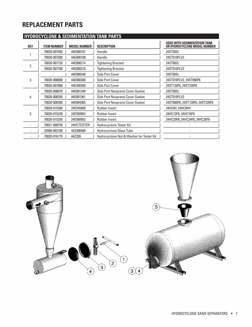
REPLACEMENT PARTS
HYDROCYCLONE & SEDIMENTATION TANK PARTS
KEY
1
2
3
4
5
---
ITEM NUMBER70020-00745070020-00750070020-00772070020-007700
-70020-00800070020-00790070020-00807070020-00835070020-00820070020-01520070020-01523070020-01525070021-00073033500-00210070020-016175
MODEL NUMBER44E00010144E00010044E00021444E00021644E00024044E00026044E40026044E00134044E00136144E00436524E54595024E55095224E56095224HCTESTER44Z40040944Z209
DESCRIPTIONHandleHandleTightening BracketTightening BracketSide Port CoverSide Port CoverSide Port CoverSide Port Neoprene Cover GasketSide Port Neoprene Cover GasketSide Port Neoprene Cover GasketRubber InsertRubber InsertRubber InsertHydrocyclone Tester KitHydrocyclone Glass TubeHydrocyclone Nut & Washer for Tester Kit
USED WITH SEDIMENTATION TANKOR HYDROCYCLONE MODEL NUMBER24ST002L24ST010FLV224ST002L24ST010FLV224ST002L24ST010FLV2, 24ST060F624ST120F6, 24ST220F824ST002L24ST010FLV224ST060F6, 24ST120F6, 24ST220F824HC8V, 24HC8HV24HC12F6, 24HC16F624HC20F8, 24HC24F8, 24HC30F8 - - -

HYDRMAN 12/12