final contract report integrated light ... contract report integrated light maintenance and...
TRANSCRIPT

FINAL CONTRACT REPORT
INTEGRATED LIGHT MAINTENANCE AND INSPECTION SYSTEM FOR HIGH-MAST POLES
Pradip N. Sheth
Associate Professor
Dominick Montie Post-Doctoral Research Associate
Mechanical and Aerospace Engineering
School of Engineering and Applied Science University of Virginia
Project Manager Michael Sprinkel, P.E., Virginia Transportation Research Council
Contract Research Sponsored by Virginia Transportation Research Council
Virginia Transportation Research Council (A Cooperative Organization Sponsored Jointly by the
Virginia Department of Transportation and the University of Virginia)
Charlottesville, Virginia
April 2005
VTRC 05-CR11

ii
NOTICE
The project that is the subject of this report was done under contract for the Virginia Department of Transportation, Virginia Transportation Research Council. The contents of this report reflect the views of the authors, who are responsible for the facts and the accuracy of the data presented herein. The contents do not necessarily reflect the official views or policies of the Virginia Department of Transportation, the Commonwealth Transportation Board, or the Federal Highway Administration. This report does not constitute a standard, specification, or regulation. Each contract report is peer reviewed and accepted for publication by Research Council staff with expertise in related technical areas. Final editing and proofreading of the report are performed by the contractor.
Copyright 2005 by the Commonwealth of Virginia.

iii
ABSTRACT
Virginia highway high-mast light poles must be inspected periodically for structural defects to prevent failures. The visual inspection methods currently used include use of binoculars and telescopes and up-close inspection with bucket trucks. These methods, while simple, do not provide a continuous visual record (e.g., image or video data) of the inspection for archive and referral. Furthermore, they do not provide a thorough inspection near the pole-top – bucket trucks cannot reach this high, and the view angle of ground-based optical equipment does not allow for a clear picture of the pole face.
This research project has produced a more thorough, ground-implemented inspection method which combines a video record of the inspection with the potential capacity to perform more detailed inspection methods (e.g., ultrasound or magnetic particle imaging). The built-in ring lowering system for maintenance of the lights, which includes the winch/cable/lighting ring hardware within the pole, is used to mount a video camera support structure that wirelessly transmits data from multiple cameras to a ground-based laptop computer. This laptop computer is used to wirelessly control the camera operation, record video data, and perform calculations to estimate and record crack dimensions and location.
Extensive field tests have demonstrated the viability of this research approach. High-resolution video data have been archived of the entire pole surface for poles in southern and northern Virginia. Pole crack dimensions have been approximated by a post-processing software developed by this project. Field test demos and actual inspections have been conducted for VDOT (Virginia Department of Transportation) personnel with the device developed and described in this report. A provisional patent protection for this system has been obtained by the University of Virginia Patent Foundation. It is recommended that the system be further refined and new inspection technologies in addition to the video capture be incorporated through the continued utilization and development of the functionality of this device. In addition, the concept of integrating the tools for maintenance with the tools for structural inspection is a powerful concept and should be explored for other highway structures as well.

FINAL CONTRACT REPORT
INTEGRATED LIGHT MAINTENANCE AND INSPECTION SYSTEM FOR HIGH-MAST POLES
Pradip N. Sheth
Associate Professor
Dominick Montie Post-Doctoral Research Associate
Mechanical and Aerospace Engineering
School of Engineering and Applied Science University of Virginia
INTRODUCTION
High-mast light/camera poles are generally 70 to 120 feet high, although MnDOT (Minnesota Department of Transportation) has poles up to 160 feet high in their inventory. These poles range in diameters from 6 inches at the top to 30 inches at the base of the pole. These poles are tapered, most with circular sections, but poles of polygonal sections are also used. Many of the poles are constructed from weathering steel, conforming to ASTM A588. These poles are made of tapered steel, which may be one piece or sectional, depending on the height, and their sections inserted one inside the other. Slip joints are formed where the male and the female sections are joined. Generally, but not always, detectable cracks form on the female section of the tube and the slip joints are typically the primary focus of structural inspections. Some poles are constructed with longitudinal (height-wise) weldments, thus making it necessary to inspect the entire pole surface instead of just the slip joints.
Virginia highway high-mast light poles must be inspected periodically for cracks to prevent failures. The visual inspection methods currently used include use of binoculars and telescopes and up-close inspection with bucket trucks. These methods, while simple, do not provide a continuous visual record (e.g., image or video data) of the inspection for archive and referral. Furthermore, they do not provide a thorough inspection near the pole-top – bucket trucks cannot reach this high, and the view angle of ground-based optical equipment does not allow for a clear picture of the pole face.
The purpose of this research was to develop an inspection tool integrated with the winch/cable based ring-lowering system originally designed for servicing of lights on the highway high-mast light poles. Within the context of this research, this inspection tool was to be used to identify potential cracks by displaying and recording video of the pole on a ground-based laptop.

2
Construction of the Highway High-Mast Light Poles
Highway high-mast light poles generally incorporate a light servicing subsystem—these subsystems are called "Lowering Device Systems" (LDSs) and come in a variety of different types, all with the objective of lowering the light fixture at the top of the pole to the ground level for servicing and testing the lights. For example, HOLOPHANE® is a major supplier of lighting systems and has the following available options for LDSs:
• Top or bottom latching systems. • Self-centering luminaire ring or non-centering with bumper. • Winch mounted within the pole base or a portable winch. • Motor mounted in the pole base or a portable drive motor.
There are a many other vendors of LDSs, for example MG Squared Lowering Systems®
markets a pole-independent, portable system for lowering the luminaire rings while Metrolux® markets a line of LDSs. MILLERBERND® is a supplier of high-mast light poles in Minnesota to MnDOT which may also provide some additional details on LDSs. A review of these systems suggests that there are indeed common elements to these systems, which include three main subassemblies: head frame, lowering ring, and winch assembly.
• Head Frame: The head frame incorporates hoist cable sheaves; the bearings for these sheaves are self-lubricating (oil impregnated) sintered bronze bushings press-fitted into the sheaves. The cables are constructed of aircraft cable, either zinc-coated or stainless steel. The head frame incorporates a power cord roller assembly. The top latching subsystem allows for the latches to carry the load of the ring when the LDS is not in operation, while the bottom latching system continues to put the load on the cable/winch system even when the LDS is not in operation.
• Lowering Ring: The lowering ring assembly can be either a self-centering ring
assembly, or a non-centering ring assembly. A self-centering ring assembly usually has roller contacts and spring-loaded interconnected arms that produce a linkage action to keep the ring concentric to the pole during the raising and lowering operations. A non-centering ring usually has a tubular, polyethylene bumper secured to the inside diameter of the ring. The bumper is designed to provide some degree of protection to the ring, pole, luminaries, and lamps by cushioning the impacts during the raising/lowering operation.
• Winch Assembly: The drive motor for the winch assembly is usually equipped with
a torque limiting coupling and also a backup shear pin as an extra safety measure to prevent transmission of high forces to the cables. This system usually is transported in a pickup truck to the site.
Benefits of the Prototype Developed in This Research
Field implementation of the tool developed in this research project can provide many
significant benefits, including the following:

3
• Consolidated, multi-purpose use of the existing winch/cable/light ring system in these poles for the inspection function as well, thereby increasing the utility of the existing hardware on these poles.
• Quantifiable cost reduction opportunity by possibly combining the periodic light
servicing function with the pole inspection function. No additional or separate inspection schedule would be necessary—inspection data would be automatically captured when the lights are serviced. Typically, the lights are serviced every 3 years, and this would also be the period for pole inspection. If on a separate inspection schedule, these poles are typically inspected every 5 years, wherein the inspection is scheduled independent of the servicing of the lights.
• More comprehensive inspection data will be available and stored in digital video
files, thereby providing permanent record of each pole in the inventory.
• Safety of the personnel who perform the inspection function will be significantly improved. This benefit will accrue particularly if the number of instances in which a person is sent up in a bucket for a closer inspection of a specific location on the pole is reduced by the device developed in this research.
• Both the quality and the quantity of the inspection data will be greatly enhanced.
Presently, the inspection data for these poles comprise visual checks with binoculars or telescopes on the ground. Suspected cracks, if sighted, are further investigated by sending a person in a bucket for magnetic particle inspection (MPI), ultrasonic testing (UT), or dye penetration. A close-up photograph is then taken of the site (with or without the results of any of these enhanced inspection techniques). The present method, therefore, produces minimal data from the pole inspection. The proposed method will capture the visual information in digital video files for permanent record of the structural health of the pole.
• The tool developed in this research will also provide the opportunity for additional,
more detailed structural inspection possibilities, including the above-listed MPI and UT for subsurface crack detection. The development for integrating either of these techniques with the proposed tool is not included in the first prototype described here, but the opportunity for expansion exists and available. As a further opportunity, a robotic arm can also be mounted on the device developed by this research, which can be controlled to operate other inspection sensors.
• The tool developed in this research may be of interest to the manufacturers of poles,
whereby these manufacturers could also market this tool, complementing their winch/cable/light ring system. This tool will be of interest to the State Departments of Transportation, and therefore, perhaps to the Federal Highway Administration (FHWA). Engineering Contractors to the State Departments of Transportation may also be interested in utilizing this tool for their contract work.

4
Comparison to Past Research
The development described in this report is a direct result of the experiences acquired from the Polecat1 crawling robotic system (described further in Appendix F) during the past few years. A brief comparison between the salient features of Polecat and of the proposed device is presented here to provide a perspective on the new device. The Polecat crawling robot is a carrier of inspection sensors (camera). The robot is fitted with magnetic wheels and a steering system to allow both the vertical and the circumferential motions of the robot to inspect the pole surfaces. The Polecat robot can be thought of as a free-moving robotic carrier, which can carry the inspection sensor to a desired height and location on the pole. The Polecat technology is thus a general-purpose robotic technology for applications to many different types of structural inspection functions. From our experiences in field inspections of poles with Polecat, it has become clear that a more efficient method would be to implement a specific robotic tool for each type of structure rather than utilizing a general-purpose tool. With the device developed and described in this report, we use the cable/winch system inherent to a pole as a carrier for the robotic inspection device—note that with the Polecat about 99% or more of the technology and the associated systems are dedicated to moving and controlling the carrier, while only 1% or less of the technology is dedicated to the inspection sensor (camera) itself. Clearly, the bulk of the technology and systems ought to focus on the inspection sensors that are the main objects for acquiring inspection data and the carrier itself should be relatively less prominent in the overall inspection system. This 99% focus on the carrier and 1% focus on the sensor in the Polecat technology are effectively reversed in this new device, where the carrier itself is now the already existing system on the pole with a specially designed and adaptable attachment, and the majority of the subsystems are devoted to the data collection and processing. The Polecat technology itself will continue to provide a valuable foundation for such applications as the inspection requirements for insides of pipes, and other steel structures where a general purpose motion and reach are needed. The Polecat system is presently tethered for power, controls, and data transmission to the on -ground computer and control system. The new tool does not require a ground-based generator for power, and in the new system all controls and data communication of digital video are accomplished through wireless transmission and reception.
PURPOSE AND SCOPE
The purpose of this project was to (1) develop an inspection tool integrated with the winch/cable based ring-lowering system originally designed for servicing of lights on the highway high-mast light poles and (2) compare the data quality of the developed inspection system to the current practice. This tool allowed the use of (1) objective sensor technology and (2) remote, wireless operation from ground level. Within the context of this research, this inspection tool was used to identify potential cracks by displaying and recording video of the pole on a ground-based laptop computer.
To accomplish this task, two subsystems were developed: (1) the mechanical system itself, consisting primarily of the mounting ring, cameras, power supplies, and wireless

5
communication devices, and (2) the software interface (GUI) used for camera control, video recording, and post-processing of data.
On the mechanical side, the innovation from this research was to adapt off-the-shelf components to the existing winch/cable system to perform wireless inspections. On the software side, the innovation was to (1) develop a video post-processing tool for crack dimensioning using the graphical programming language LABVIEW® and (2) combine various existing software tools under one umbrella program developed using LABVIEW®.
The scope of the work was to test the tool using one type of sensor technology (video) on several VDOT poles (with various lighting ring configurations) and to compare the results to the visual process now being utilized by VDOT.
METHODS
The method utilized for developing and field testing the device integrated with the LDS consisted of the following major steps.
1) Reviewed the process with VDOT and also with representative users to identify the most appropriate ring structure and to confirm the efficacy of the integrated process. The concept of the integrated device was first introduced very briefly and without any detail in the October 2003 meeting of North Central States Consortium. After the provisional patent protection for the system was obtained in July 2004, a more detailed presentation was made at the September 2004 meeting of the North Central States Consortium. This Consortium consists of Bridge and Structures Engineers from the Transportation Departments of North Central States (e.g., Minnesota, Wisconsin, Michigan, Kansas, Iowa, etc.), Engineering Contractors, and a LDS manufacturer (MILLERBERND) was also represented in this Consortium. The feedback from these presentations was highly encouraging. Further, with VDOT’s help, a “dry run” on the ring lowering process was carried out at the I-81 South Troutville Exit Weigh Station. Subjective assessment was made for the vibrations and jerks that may be present in the lowering/raising process. These vibrations were determined to be very low and are not expected to affect the performance of the system.
2) Based upon the results from item 1) above, a general overall specification of the
inspection system was developed. These specifications included general, "non-quantitative" parameters for the expected weight; connect/disconnect features, configuration of the data collection system, configuration of any controls required, and the operational specifications for the computer for video capture. In addition, the possibility of mounting a portable tachometer/encoder on the motor shaft or any other suitable means to measure the elevation of the ring as the ring is raised or lowered was considered. The elevation dimension, if integrated with the video data, would provide an indication of the location of the data during analysis of these data. It was

6
also decided that a widely applicable tool will be developed, not just for one vendor’s LDS.
3) It was decided to build a ring-mounted system for inspection, because such a design
would be the simpler design relative to the other possibility of a cable-mounted system. Experiment on a conveniently located pole in the field (I-81 Troutville Weigh Station) for checking out the motor controls and elevation measuring system. The elevation measurements can assist in synchronous data on the location of the video information.
4) The inspection tool fixture was designed—this design included the mechanical design
with particular focus on the ease of assembly and disassembly in the field, possible selection of lightweight high-strength components, issues such as the need for controlling the location/orientation of the cameras, and interactions between the multiple cameras. Whenever possible, off the shelf stock parts were selected to minimize machining and fabrication costs.
5) The commercial camera systems with particular emphasis on the wireless processes
and control requirements were investigated. Wireless video data transmittal and storage systems, memory size requirements, any wireless control requirements, and a PC-based data acquisition system were the key issues.
6) All necessary components and subsystems were purchased and assembled. These
purchases were made as individual subsystems were defined to allow separate checkout and testing before a full system was put together. The entire prototype system, including the mechanical and the data acquisition/control subsystems, was assembled for field demonstrations.
7) The system was demonstrated to VDOT in July 2004 at the I-81 South Troutville
Weigh Station. Further, several poles in the Northern Virginia I-66/I-95 corridors were inspected and results compared with the data from the Subcontract Engineers' Reports of inspections completed with the traditional techniques.
8) Document the entire project in periodic and final reports.
RESULTS
Overall Configuration of the System
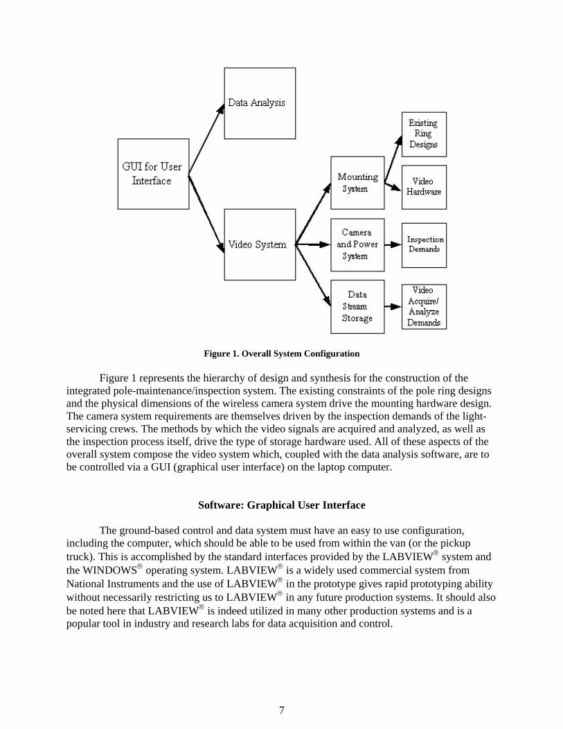
Figure 1 shows a block diagram representation of the overall system configuration.
7
Figure 1. Overall System Configuration
Figure 1 represents the hierarchy of design and synthesis for the construction of the integrated pole-maintenance/inspection system. The existing constraints of the pole ring designs and the physical dimensions of the wireless camera system drive the mounting hardware design. The camera system requirements are themselves driven by the inspection demands of the light-servicing crews. The methods by which the video signals are acquired and analyzed, as well as the inspection process itself, drive the type of storage hardware used. All of these aspects of the overall system compose the video system which, coupled with the data analysis software, are to be controlled via a GUI (graphical user interface) on the laptop computer.
Software: Graphical User Interface
The ground-based control and data system must have an easy to use configuration, including the computer, which should be able to be used from within the van (or the pickup truck). This is accomplished by the standard interfaces provided by the LABVIEW® system and the WINDOWS® operating system. LABVIEW® is a widely used commercial system from National Instruments and the use of LABVIEW® in the prototype gives rapid prototyping ability without necessarily restricting us to LABVIEW® in any future production systems. It should also be noted here that LABVIEW® is indeed utilized in many other production systems and is a popular tool in industry and research labs for data acquisition and control.

8
The Graphical User Interface (GUI) that allows the user to perform such ground-based control should incorporate three main parts:
1. A window for controlling the camera operation (zoom, focus, pan, tilt, etc.) as well as video storage (saving streaming camera video to hard drive). Figure 2 is a sample screen from the wireless system used in the final stages of this research project.
Figure 2. Illustration of the GUI Window Used in This Research
The video capture software used is a product from TechSMITH called Camtasia Studio 2. This software records video displayed using the wireless camera’s built-in software (which does not provide a recording function), compresses the video using one of a number of methods, and edits the video to remove sections of one video file or to combine all or parts of several video files together into a single file (see Figure 3 for a sample screen).

9
Figure 3. Illustration of the Video Capture Software
2. A “help” window (Figure 4) for descriptions of purpose and operation of all software functions. While the software is designed specifically for simplicity and ease of use, this window displays help text for all software functions to aid first-time users.
Figure 4. “HELP” Component of GUI

10
3. A window for post-processing of data – currently, crack measurement capability. This window is important once pole data (video) have been collected. The user is then able to import the video into this window for an in-the-field measurement of any visible cracks. This feature is described further in the next section.
Software: Crack Measurement
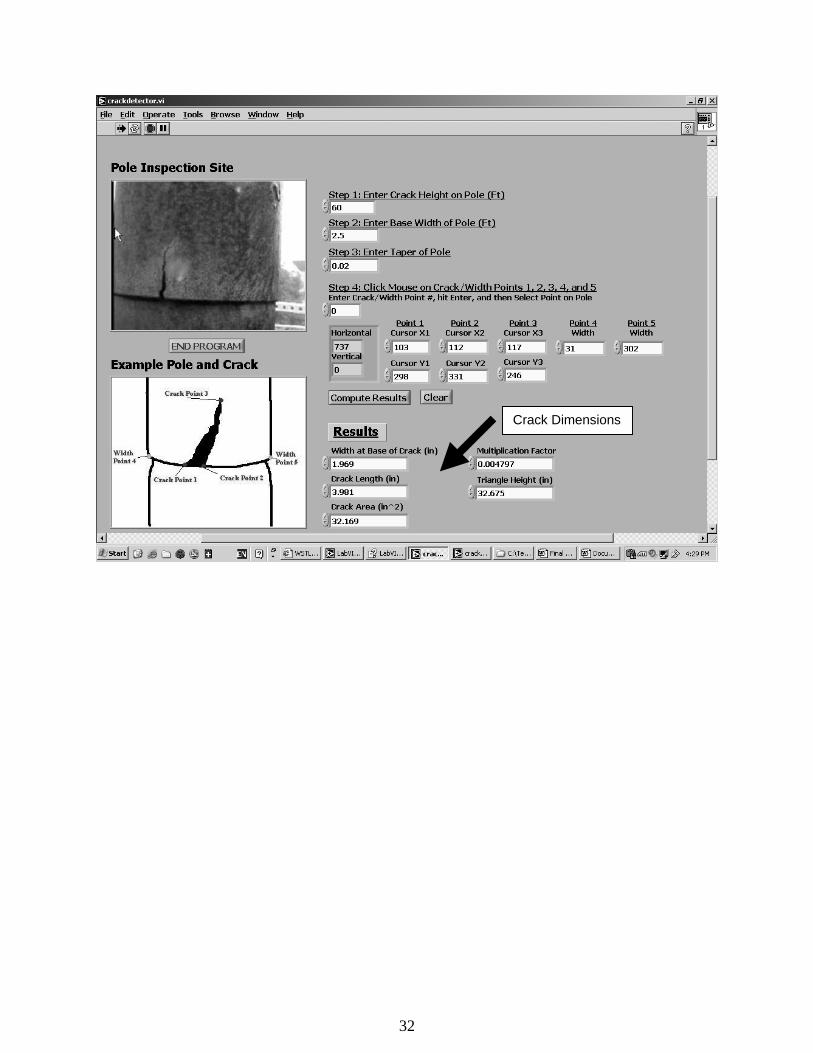
Included in the software prototype is a calculation to approximate crack dimensions based on measurements taken in the field and of the screen image of the crack. The technique is based on comparing distances measured on a computer screen when looking at a video or image file and using known data to calculate true distances from screen-measured distances. The algorithm uses the following method:
1. Use a tape measure to measure the actual width of the base of the pole. 2. Use the ultrasonic distance measurement device included within the system to
measure the distance from the base of the pole to the crack. 3. Calculate (done automatically in software), from knowledge of the pole taper, the
actual width of the pole at the crack 4. Use the software to calculate the screen image dimensions of the crack as compared
to the screen image width of the pole. 5. Calculate (done automatically in software) the actual dimensions of the crack based
on the relationship between screen image pole width and actual pole width at the crack.
Using only two measured pieces of data, and the manufacturer supplied pole taper specifications, the prototype LABVIEW®-based software program produces crack dimensions (height and width). The benefit of this method is that all crack measurements can be performed either in the field or at the home office after field data have been collected. While it is not an explicit measure of crack dimensions, the video quality of the camera data is such that satisfactory resolution (and thus dimension accuracy) can be achieved. An advantage to using LABVIEW® is that, in subsequent research when more features and capabilities are added to the software package, many of these steps can be automated using LABVIEW®’s built-in crack analysis tools. A screen shot of the crack detection software is shown in Figure 5, and images in Appendix A are supplied with crack measurements that were calculated using this software.

11
Figure 5. Crack Dimensioning Component of Software
Mechanical Design: Existing Lighting Rings
The design of the mounting hardware is driven by the existing design of the lighting rings (upon which the cameras will be mounted) and the video capabilities of available wireless cameras. Based on prior fieldwork, two primary makers of LDSs are HOLOPHANE® and MILLERBERND®. These two LDSs are considered sufficiently general and, therefore, the mounting system design is based on these two LDSs.
LDS Manufacturers HOLOPHANE®:
• Ring Diameter: From HOLOPHANE® website (http://www.holophane.com) – “Diameter of assembly with luminaries varies from 8 to 11 feet.” Actual ring diameters are likely 3-6 feet, based on past fieldwork observations.
• Ring Material: Galvanized steel
Figure 6, taken from a field test of a HOLOPHANE® ring at I-81 South Troutville Exit Virginia Weigh Station, shows the overall design of the complete ring/light system. It is important to note that, unlike the MILLERBERND® rings, the HOLOPHANE® rings have components mounted on the top and bottom of the ring. While this does not prevent the same mounting system being used on both types of rings, it does drive the design and the way in which

12
it should be mounted. This is further discussed below under the heading “Mechanical Design: Mounting System.”
Figure 6. HOLOPHANE® Lowering Device Ring/Light System at I-81 Troutville, Virginia Weigh Station MILLERBERND®:
• Ring Diameter: Poles inspected in Minnesota were approximately 3-4 feet in diameter.
• Ring Material: Stainless steel
Figure 7 shows the MILLERBERND® ring. There are several differences between this ring and that designed by HOLOPHANE®. First, there is less equipment mounted on the ring (no mechanism to signal the pole-top has been reached and no self-centering mechanism). While the design is simpler, and thus could potentially allow for a simpler camera mounting design, the lack of a self-centering mechanism is critical. The bumpers (dark rubber rings on the inside of the main stainless steel rings) provide the protection to the steel rings as it is lowered (under windy conditions, for instance). This means that the distance from any point on the ring to the pole could vary considerably (from a few inches to several feet). Furthermore, lacking a self-centering mechanism, which provides pressure against the pole, the ring will likely twist considerably as it is lowered. Therefore, a point on the ring at the north face of the pole at the pole top may very well end up at the east face of the pole by the time the ring is fully lowered.
The self-centering issue is thus critical for two reasons. First, the auto-focus of the cameras must function properly at a potentially small distance from the pole, or the cameras must be mounted sufficiently far from the pole to prevent a lack of focus at maximum eccentricities. Second, to ensure full examination of the pole, several cameras must be used in unison, so that given any rotation of the ring, the entire pole circumference is still in view by using all the cameras.

13
Figure 7. MILLERBERND® Ring – Photograph Taken During a Minnesota Field Trip
While there are critical differences between the rings of these two manufacturers, the overall design is similar - a ring supporting multiple lights, each supported by an extending rod mounting perpendicularly to the ring. This fact allows for the potential of an all-purpose camera mounting design to be used for rings of both manufacturers.
Mechanical Design: Mounting System
It was determined that the camera mounting system must serve three main functions:
1. Provide mounting hardware for multiple cameras. Multiple cameras must be used, as dictated by the MILLERBERND® ring design. Because the ring has the potential to twist during lowering/raising, use of one camera over several passes cannot guarantee that all points of the pole will be viewed. Furthermore, the closer a camera gets to the pole, the smaller its viewing angle. Thus, points in that camera’s nominal viewing angle that could be viewed under a centered-ring position can no longer be viewed by that camera, and thus must be viewed by the others. If only three cameras are used, when one is very near the pole, there will likely be points on the pole that cannot be viewed by the other two. Therefore, there will need to be at least 3 cameras (depending on camera range of views, focal ranges, and ring design). Furthermore, because the focal angle of the camera may vary widely with the motion of the ring, the cameras must be auto-focus. It would be extremely difficult for the operator to continuously vary (through the GUI) the focal ranges of all the cameras as the ring is lowered or raised. For the scope of this project, however, which applies primarily to Virginia poles (all of which have self-centering mechanisms), three cameras are sufficient – the standoff distance allows for nearly 180 degrees view angle, which provides overlap for view of cracks at the edge of any one camera’s field of view.

14
2. Provide mounting hardware for the wireless components, their power supplies, and the power supplies for the cameras. The mounting hardware must have a quick connect/disconnect ability with the light ring, or with the cable/winch system. A widely applicable system would provide a general-purpose tool for broader variety of designs of LDSs for the pole. This design requirement also dictates that the inspection device, while being generally adaptable to a number of different designs of LDSs, must also be reliable and quickly adaptable. Thus a clear trade off must be followed and "generality" must be limited in favor of "usability." Designs from a number of different vendors of LDSs are considered, but the highest priority is of course for the major supplier to the VDOT, i.e., HOLOPHANE®. It is also noted that restricting the device to a current vendor to VDOT can also lead to a too restrictive design. Thus, there is a need for a careful trade off between generality and adaptability.
3. Provide a positioning layout to ensure proper camera angles. This is important to
ensure that the entire circumference of the pole is in view. For example, the positioning ring should provide 120 degree spacing markers if 3 cameras are used, and markers spaced 90 degrees apart if 4 cameras are used. Proper camera placement is important to ensure full pole view using the smallest number of cameras possible (the fewer the number of cameras, the cheaper the inspection system and the easier it is the mount, dismount, and store the hardware). Again, for the purpose of this project (as it applies to Virginia DOT poles), three cameras are sufficient due to the self-centering mechanisms on all such poles.
The final design for the mounting hardware uses square perforated steel tubing where the bolts are inserted in the holes along the tube (Figure 8) instead of in slots machined into slats. For this concept, the camera modules are mounted directly to this variable-diameter ring at points pre-marked for proper camera placement. This variable-diameter mounting adaptor design is shown in Figures 8 and 9, at maximum diameter in Figure 8 and at a smaller diameter setting in the Figure 9.
Figure 8. Adapter Ring, Maximum Diameter

15
Figure 9. Adapter Ring, Reduced Diameter
This adaptor is made from perforated stainless steel bars, where each pivot point is secured, for simplicity of assembly/disassembly and use, with a bolt/cotter pin, which eliminates the need to tighten each pivot point and the potential for lost nuts and washers. As Figures 8 and 9 demonstrate, the nominal diameter can be adjusted by adjusting the pivot bolts (generally, symmetrically, unless an application requires an asymmetric configuration) at holes along each bar. Because the pivot points are no longer secured, the shape of the adaptor is fixed with plates that are used at each corner of the adaptor to fix the angle between any connected bar to 120 degrees. This ensures a symmetric configuration of the adaptor (if so desired) that remains fixed without the need to approximate a symmetric assembly by eyesight, and then tighten each nut to prevent relative motion between linkages. One such plate is shown in Figure 10.
Figure 10. Shape-Fixing Plates

16
This adaptor also offers the advantage that the cameras, wireless equipment (power supply, router, etc.), and robotic devices (arms, robots, etc.) used for more detailed inspection (ultrasound, magnetic particle imaging, etc.) can all be mounted easily on the adaptor using any free holes along the bars. For instance, this provides for easy camera placement for a clear line-of-sight of the pole – any hole can be used to provide unimpeded viewing for the camera modules. HOLOPHANE® ring systems, for example, have cables, power inverters, power lines, etc. that restrict clear line-of-sight viewing at various points along the perimeter of the ring.
The ring adaptor is attached to the lighting ring with U-bolts, which is an easy and quick way to provide accurate ring placement and rigid attachment to the lighting ring. This is demonstrated in Figure 11.
Figure 11. U-bolt Attachment of Ring Adaptor
Camera and Wireless Router Modules
The following camera system specifications were developed after several initial field tests, all of which are either met or rendered unnecessary by the current system:
• 1 ft. focal distance – Camera must be able to focus on objects as little as 1ft away, as this is a typical stand-off distance from the base of the pole
• Wireless – Camera must be able to operate without a tether for communications/data transfer
• Battery-operated – Camera must be able to be run from a ring-mounted battery/UPS system to eliminate the need for a power tether
• Zoom – Camera must have a remotely-controlled optical zoom that can focus from distances of as little as 1 ft. to allow the user to zoom in on possible crack locations
• Wide temperature and humidity range – Camera should be able to operate in a reasonable range of heat and cold (40-100ºF) and humidity. As this is a combined inspection/maintenance device, the camera must be able to be operated when lighting ring bulbs must be replaced, which could be any time of the year.

17
• Strong signal – Camera should be operated in an environment with a lot of outside interference (e.g., cell phone, CB, radio signals). Either this requires a signal booster (for 802.11b communication), or operation in frequency ranges outside of these common devices (802.11a communication)
• Automatic focus/iris – Camera should be auto-focus, and be able to adjust itself for varying light conditions (cloudy day or bright sunlight)
• Weatherproof – Camera should be operable in light rain, snow. Because it takes 10 minutes to lower the ring, as well as time for removal, the camera should be able to operate in light rain that occurs when the camera is at the top of the pole.
• Resolution (at least 640x480) – Camera pixel density should be enough to provide acceptable resolution to spot small cracks (and differentiate cracks from marks or dirt, etc). The image files will be analyzed with a LABVIEW®-based image analysis package, and better resolution will yield better results from this analysis software.
The following specifications have been developed for a power supply based on many
field tests:
• Must provide enough power to operate all cameras for inspection of at least three poles
• Must be as compact and light as possible so as not to overstrain on the ring/cable system, and to provide for easy transportation, mounting, and dismounting
• Must be able to provide power with the flip of a switch or the push of a button.
Figure 12. Camera Module
The camera module consists of 4 components: the camera itself, a wireless transmitter, the power supply, and connecting cables (power and Ethernet). The camera itself is not wireless; the video is accessed from an Ethernet port. Therefore, a wireless transmitter is connected via an Ethernet cable to the camera output to enable wireless transmission. A single DC power supply is
Router Module
Camera
Video transmitter
Power Supply

18
used to power both the camera and the wireless transmitter. This power is supplied to the two devices via a cigarette-lighter style adaptor. Because both the camera and wireless transmitter run on DC power, the advantage of this configuration is that there is no need to convert DC power to AC, and then use the manufacturer-provided AC adaptors to then convert back to DC power. This module, therefore, is a stand-alone unit that can be fixed anywhere on the support ring that provides the camera a suitable view of the pole, which provides easy assembly/disassembly of the system in the field. Field tests have shown that at least four poles can be inspected using fully charged DC power supplies before recharging (12-hour recharge time). To perform more pole inspection in a single day, a replacement set of power supplies is all that is needed. The specifications for each of these components are provided in Appendix C.
On the current system design, there are three camera modules (to provide a full circumferential view of the pole, with each camera placed approximately 120 degrees apart) and one wireless router module. The wireless transmitters on each camera module transmit the video signals from each camera to the wireless router module, which transmits these three signals to the ground for viewing and storage on a laptop. Also mounted on the wireless router module is an ultrasound distance measurement device. This device, in conjunction with a handheld transmitter/receiver unit, allows the user to measure the distance between the handheld unit and the ring-mounted receiver. This provides a cheap and easy way to measure the distance from the pole bottom to any cracks or points of interest, which can then be recorded for location and identification in subsequent inspections.
There are thus three wireless systems in our design. One system is ring-based, and is used to supply the wireless router with the video signals. Another system is the wireless transmission from the ring-based router to the ground-based laptop. The wireless router module can be seen in Figure 12, to the left of the camera module, and its specifications are provided in Appendix C. The final wireless system is that of the ultrasound distance measurement device, whose specifications are also listed in Appendix C.
Figure 13 shows all the camera modules in place (using the current mounting scheme) for a field test. Not seen in the figure, but present on the ring, are positioning markers to indicate 120 degree spacing for the cameras. While exact placement is not necessary to provide a full circumferential view of the pole (as explained above, because of the presence of self-centering mechanisms on VDOT poles), the markers provide useful guidelines for proper module placement.
Field tests proved mounting the wireless router on the underside of the ring to provide better signal direction and strength for transmitting video to the ground-based laptop. Furthermore, it is necessary to mount the ultrasound distance measurement device on the underside of the ring to provide a direct line-of-sight to the transmitter/receiver device.
Figure 15 shows the variable-diameter mounting adaptor as seen from below, when the ring is approximately at one-third the pole height.

19
Figure 13. Placement of Camera Modules
Figure 14 shows the wireless router module and attached ultrasound measurement device.
Figure 14. Router and Distance Measurement Device
Module 2
Module 1
Module 2
Module 3
Distance-Measurement Device
Router
Distance- Measurement Device

20
Ring Adaptor
Camera Modules
Ring Adaptor
Camera Modules
Figure 15. Bottom View, Entire System in Operation
The adaptor ring and camera/router module design satisfies all the specified design requirements for the system. The ring and module design provides:
• mounting of all camera/router modules and associated power supplies and wiring • adjustable mounting locations and configurations • mounting markers for module spacing guidelines • a quick connect/disconnect method for attachment to the lighting ring • wireless transmission of video to the ground-based laptop.
While the adaptor ring does not maintain a fixed distance from the cameras to the pole
surface due to the pole taper, the auto-focus and zoom features of the cameras eliminate the need for this requirement.
The camera chosen for this system satisfies all the video requirements, with the exception of wireless capability. The adaptation of the cameras for wireless transmission has been described above, which completes the satisfaction of all video requirements.
Video System and Storage Specifications
The following specifications have been developed for the field computer after many field tests using several types of computer systems:
• Laptop – Must be mobile and should not need a generator for operation (a desktop
system used in prior field test was neither, and was an unnecessary burden).

21
• Large hard drive (80GB) – Must have sufficient hard drive space to store large video files.
• CD/DVD writer – Must be able to backup in the field the video files, which will also free up space on the hard drive (back up a series of poles onto CD, then can erase from laptop hard drive).
• Wide screen – Must have a screen that is easy to see by more than one person (should more than one person in the field want to view the data as they are being collected) and that can simultaneously display video from three or more cameras at a screen size that allows the user to identify potential cracks.
• Fast processor (at least 1GHz) – Must be able to process multiple video feeds simultaneously.
• Low-power consumption (processor should be equivalent or superior to a Pentium M for performance and power consumption) – Must be able to operate for up to 6 hours to test a day’s worth of poles
• Extended battery life - Must be able to operate for up to 6 hours to test a day’s worth of poles.
• Non-glare screen – Bright sun makes it very difficult to see the screen, so a non-glare screen is necessary to use the laptop outside of the van.
The laptop chosen for this research satisfies all requirements for processing and storage
of video.
Quantitative Cost-Benefit Analysis
Many of the benefits that will accrue from this device cannot be quantified without a great deal of assumptions. However, we can quantify one specific aspect of the cost reduction, which then gives us an estimate of a minimum and conservative cost reduction possibility. This analysis is based on the forecasted cost for pole inspections provided by the Structure and Bridge Division of Virginia Department of Transportation (VDOT) in an email dated June 18, 2003 to the Virginia Transportation Research Council (VTRC).
At present, VDOT uses a five-year frequency for pole inspections. Therefore, in 10 years, VDOT would inspect high-mast lighting poles twice assuming the first inspection is complete. Presently, VDOT has 686 high-mast poles inventoried. Assuming one hour per pole for inspection using the conventional method of binoculars/telescope, one vehicle per team and a team of two inspectors, and no increase in wages in ten years, we have for the conventional method of pole inspection,
Average cost of two inspectors (including overhead) = 2 $50 / hour $100 / hour× = Average cost of the van = $5/ hour
Therefore, over 10 years with two inspection cycles (5-year period), the projected cost is
( )686 100 5 2 $144,000× + × =
The present VDOT thinking is that high-mast lighting is going to see an increased usage, possibly doubling or tripling the number of poles from the present inventory of 686 poles. In

22
addition, allowing for a small increase in inspection costs, it can be projected that the VDOT will likely spend $300,000 to $400,000 over ten years, or an average of $30,000 per year for pole inspections. This cost projection is in addition to the costs associated with the periodic (every 3 years) servicing of the lights.
Now consider the integrated inspection and light servicing method described in this report. First, the light-servicing interval is very likely a random event; an estimated Mean Time Between Failure (MTBF) is 3 years. When the light service event occurs, the service team utilizes the winch/cable system to lower the ring to the ground level and service the lights as a standard operating procedure. While the ring is at the ground level, the service team will also mount the inspection system on the ring and then raise the ring over the pole to the top level, while capturing the visual data for the entire pole surface. The ring will then be lowered again to retrieve the inspection device and then raised and affixed to the head frame, thus completing two passes on the pole as contrasted with a single pass if this were only a light servicing function. While the inspection plus servicing will of course take longer to perform than light servicing alone, combining the two functions will take less time than each function performed independently. The visual data from the cameras will be captured in digital form on the ground for a permanent record while concurrently displaying these data in real time on a monitor on the ground for real time analysis.
In essence, therefore, we can eliminate the pole inspection function as a separately scheduled activity, with the attendant subcontracting issues and costs. Further, it is a straightforward process to upgrade/train the light servicing crew to mount and use the inspection device and even perform some interpretation of the real time vision data. Of course, the visual data are also available in digital files for processing and interpretation at the VDOT office. We have targeted for cost reduction a conservatively estimated $30,000 per year, while at the same time possibly upgrading the light servicing crew (personnel development) and acquiring significantly improved quality and quantity of inspection data. If this cost reduction and consolidation is extrapolated to all other state DOT’s, it is clear that a substantial cost reduction opportunity exists. In this analysis, the cost for the additional time required to rig and inspect a pole, possible additional inspections going from a five-year frequency to a 3-year frequency, the cost of training these "new" inspectors and due to an increased level of expertise of individuals performing the "servicing," the possible increase in the hourly rate of the "inspector/serviceman" must all be procedurally worked out.
While individual costs are difficult to quantify and must necessary be lumped into approximate overall costs which may turn out to be far different from that predicted here, the one cost not included but which may be the most important is the cost savings of a prevented failure. One pole failure on a busy highway could produce catastrophic costs that dwarf all costs quantified here. Therefore, any minimal increases in the “insurance” cost of this device potentially far outweigh the devastating costs of a single failure which may have been prevented with the knowledge obtained using this device.
This analysis only considers visual inspection data, because visual inspection is the present standard inspection for high-mast poles and the cost reduction analysis can be compared on "apples to apples" basis. On this basis, this new inspection tool provides a much more

23
comprehensive view of the pole, at a direct line-of-sight with up-close views possible, than the current methods. Appendix A demonstrates the advantage of this method by comparing the data from current inspections to the data gathered using this new tool.
Furthermore, this new inspection tool now also creates further advancement opportunities of conveniently integrating other NDE sensors such as MPI and ultrasound, and also for more thorough data analysis in real time. This is because the entire carrier is already in place, and one can mount lightweight, remotely controlled robotic devices for these advanced NDE sensing tools. This would fall under the "intangible" benefit category in this cost analysis, but has the potential of significantly out weighing all other cost-benefits.
DISCUSSION
The primary result of this research is a simple and effective device which produces archived video data of high-mast light pole surfaces, as well as a way to measure and record crack dimensions and heights. This capabilities and data this device provides are far superior to current methods of visual/surface inspection of high-mast light poles.
A sample image of a pole crack is shown in Figure 16, with dimensions that were calculated from the dimensioning software and height that was measured using the ultrasound distance measurement device. This image is just one frame, however, from a collection of full pole video data that have been collected from seven poles in Virginia. These data have been archived and are available for subsequent review of the inspection of each of these poles.
In testing this device, we have conducted a full field demonstration at the I-81 Troutville
exit weigh station for VDOT, Collins Engineers, and Schwartz & Associate employees. Complete pole data from this demonstration have been archived, and a video of complete system setup and discussion has been archived from this event as well.
Further testing in Northern Virginia has produced archived video of complete pole inspections for 6 more poles (4 of which have cracks, 2 of which have recently been replaced and have no cracks).
Each field test highlighted inefficiencies or deficiencies in the design of the system that were then corrected, and resulted in a system that is relatively simple, composed entirely of off-the-shelf components, and is very effective at achieving its desired objectives. Recommendations for further improvements, based on these field tests, are highlighted in the Recommendations section.
The field demonstration and subsequent presentation of this research to VDOT personnel has resulted in significant interest of further research to develop the capabilities of this device. Specifically, there is interest in producing an ultrasound module capable of performing subsurface crack detection. This type of module can significantly enhance the functionality of the device. Furthermore, this type of module can be adapted for other highway structures, including

24
bridge and sign structures. While many possible forms exist for this module, the concept currently being considered is a robotic arm-mounted device which can be controlled via the ground-based laptop, and whose data can be remotely monitored and archived on the laptop.
Figure 16. Sample Image of Pole Crack Laser-based ultrasonic testing equipment makes the development of this ultrasonic
inspection module relatively straightforward. These laser-based devices allow for remote, rapid scanning over rough, non-polished surfaces to detect subsurface flaws and surface micro-cracks. Should an adapter ring-mounted module be used, both the UT device and the robotic arm can be purchased off-the-shelf for simplicity. Should a ground-based device be used, only the UT device need be purchased.
The key to making this module user-friendly, however, is the non-mechanical aspect: the software. A LABVIEW®-based interface should be used because of its versatility, and to allow it to be incorporated into the existing software tools produced for this application. Start-up, self-check and self-test, UT device/robotic arm operation, data post-processing functionality all must be incorporated into this program, as well as all necessary instructions for operation. Furthermore, a simple testing protocol must be defined which produces accurate and repeatable data without a steep learning curve.

25
Candidate UT devices and robotic arms have already been considered, and the necessary experience with LABVIEW® has been acquired to produce a simple user interface for data acquisition and post-processing. With timely support for this research, a prototype module could be developed by the time a market-ready prototype for the completed inspection device is produced.
One final interesting result of this research is that a provisional patent has been filed by the University of Virginia Patent Foundation, and negotiations with a third party are currently underway to explore the possibility of commercialization of this product.
CONCLUSIONS
This research was entirely successful in its attempt to develop a wireless video inspection system that acquires and archives total pole surfaces for identification, location, and measurement of surface cracks. After many field tests, demonstrations, and presentations, the authors have refined the system to its current state. While more improvements must be made before commercialization is possible, the prototype system demonstrates the potential for success of such a device.
RECOMMENDATIONS
The following recommended improvements to the design of the system follow directly from the extensive field testing performed, and represent those improvements that will likely be necessary to produce a commercial-grade product useful for mass-distribution of this device within Virginia and throughout the United States:
• Further simplify the camera modules to make them more robust. Currently, the cigarette light adaptor method is used, but hard-wiring the cables would be better to prevent broken connections or loss of power.
• Implement a remote-controlled way to shut off power to the modules. This is
important to save power, since the power supplies can only hold a few hours of power. For instance, once video data have been taken on the trip up the pole, no more data are necessary, so the components could be shut off for the return trip to the ground.
• Enclose each module in a waterproof housing to prevent damage to the electronics in
the case of sudden rain showers. This is important if the equipment is at the top of the pole when showers strike, since the trip duration of the ring system is about 15 minutes from top to bottom.

26
• Develop a simpler method to adjust the diameter of the ring adaptor. While the current bolt/cotter pin method is acceptable, it is nevertheless slightly difficult to perform in the field where a flat surface for adjustment may not be available.
• Use a lighter-weight material for the adaptor ring than steel, perhaps aluminum or
hard plastic. While the ring must be rigid and robust, steel is too heavy for a commercial-grade system.
• Use a camera capable of panning and tilting to accommodate viewing the pole at
different angles or for switching the direction of view mid-inspection when the camera is far above the ground. The situation may occur if, upon traveling up the pole, the ring assembly shifts to one side, causing the cameras to have partial views of the pole. Another situation would occur if a potential crack would better be viewed from an angle above or below the crack. Furthermore, this makes it unnecessary to fine-tune the mechanical fixation of the module to the ring – the fine-tuning of view angle can be done through software, reducing setup time. Finally, should a crack be located at the edge of the fixed-view camera, the zoom functionality is limited, since with increased zoom the field of view of the camera decreases, which would result in the crack being zoomed out of the screen.
• Eliminate all nut/bolt combinations on the system, and any small parts that are
attached and removed during assembly/disassembly. Invariable, parts fall in the grass, dirt, mud, etc. and are lost; the fewer small parts, and fewer parts in general, the better.
• Further develop the software to be more user-friendly and to provide more capability.
For instance, it would be helpful to have a complete database of pole dimensions (base width and taper) so the user can just insert the pole number, specify crack height, click on the crack boundaries, and have the software calculate actual crack dimensions.
• Add video compression capability to the software. Such post-processing video
compression is necessary for archival purposes, since raw video data files are far too large for mass storage (20 Mb per second for a basic real-time compression, up to 1 Gb per second for raw video data).
• To fully use the capabilities of the camera resolution, an even more powerful laptop
may need to be used. Simultaneous video monitor and capture of several high-resolution video feeds requires significant processing power. Further, any real-time compression of the video data significantly adds to the processing power requirements.
• Incorporate an anti-glare filter, and perhaps an external light, for the laptop screen.
Screen glare is a constant problem, especially on sunny days where adequate shade is not available. For better in-field crack identification, an effective anti-glare system must be developed.

27
• Develop a simple and robust method to recharge the power supplies on the modules, and to monitor the remaining power during in-field use. A quick interchange method should also be developed to switch out used power supplies for fully charged ones during extended field inspection sessions.
While this list is not comprehensive, it does list the primary improvements that should be
made to make this device robust enough for mass distribution and implementation.
ACKNOWLEDGMENTS
The authors wish to thank the Virginia Transportation Research Council for the funding and general support for this project. Specifically, they wish to thank Michael Sprinkel for his ongoing support and enthusiasm for this project. It is because of this assistance that the authors have been able to conduct this research, produce a prototype useful for VDOT inspections, demonstrate the cost-savings and cost-effectiveness of this device for the state of Virginia.
We would also like to thank the members of VDOT who helped us perform the field tests, including Mohmedsharif Munshi, Benjamin Queipo, George Croy, and Joe Smith. Special thanks also go to John Coleman of VDOT.
REFERENCES 1. Sheth, P. Use of Robotics for Nondestructive Inspection of Steel Highway Bridges and
Structures. VTRC 05-CR8. Virginia Transportation Research Council, Charlottesville, 2005.

28

29
APPENDIX A
Comparison of Current Contractors’ Data to Authors’ Data
In this appendix, information on cracks from several poles in Northern Virginia from Collins Engineering reports has been supplied. The authors wish to compare the information in their reports to crack images taken from video using our system, with calculated crack dimensions drawn on these images.
COVER SHEET
County Prince William Inspection Type Regular
City N/A Longitude 771901.7 Route
ID IS00095S
GPS Coordinates Latitude 383537.5
Location Description
On I95S, at weigh station near mile marker 154.1.
Lead Inspector Collins, Eng.
Additional Inspectors
Collins, Eng.
Front View

30
GENERAL DATA
OVERALL STRUCTURE COMMENTS
None.
WORK PERFORMED SINCE LAST INSPECTION
Unknown.
POLE DATA
Slip Joints Comments
RATING = F
3/8" crack on 2nd joint on NW side.
RECOMMENDATIONS
Poles, Vertical Supports
Priority =
(L) Repair crack.

31
Visual Data from the Field Tests with the Device of This report
The images in the crack dimensioning software have been taken from the video data acquired using our inspection device. The crack dimensioning software has been used to calculate these crack dimensions.
Crack Dimensions
32
Crack Dimensions

33
COVER SHEET
County Fairfax Inspection Type Regular
City N/A Longitude 771326.4 Route ID US00050
GPS Coordinates Latitude 385157.8
Location Description
On US50E, on exit ramp from I495S.
Lead Inspector
Collins, Eng.
Additional Inspectors
Collins, Eng.
Front View

34
GENERAL DATA
OVERALL STRUCTURE COMMENTS
WORK PERFORMED SINCE LAST INSPECTION
Unknown.
POLE DATA
Vertical Support
Comments RATING = F
Cover plate is loose. 3/8" crack at first slip joint on west side.
RECOMMENDATIONS
Poles, Vertical Supports
Priority =
(L) Repair crack; (L) Replace cover plate.

35
Visual Data from the Field Tests with the Device of This report
The images in the crack dimensioning software have been taken from the video data acquired using our inspection device. The crack dimensioning software has been used to calculate these crack dimensions.
Crack Dimensions

36
COVER SHEET County Fairfax Inspection Type Regular
City N/A Longitude 771255.8 Route ID US00050
GPS Coordinates Latitude 385159.2
Location Description
On US50W, between US 50W and Fairview Park, South ramp to US50W.
Lead Inspector
Collins, Eng.
Additional Inspectors
Collins, Eng.
Front View

37
GENERAL DATA
OVERALL STRUCTURE COMMENTS
None.
WORK PERFORMED SINCE LAST INSPECTION
Unknown.
POLE DATA
Vertical Support
Comments RATING = P
4.5" crack on north side of 3rd section near slip joint. Cover plate is loose.
RECOMMENDATIONS
Poles, Vertical Supports
Priority =
(L) Repair crack; (L) Replace cover plate.

38
Visual Data from the Field Tests with the Device of This report The images in the crack dimensioning software have been taken from the video data
acquired using our inspection device. The crack dimensioning software has been used to calculate these crack dimensions.
Crack Dimensions

39
APPENDIX B
Alternative Designs
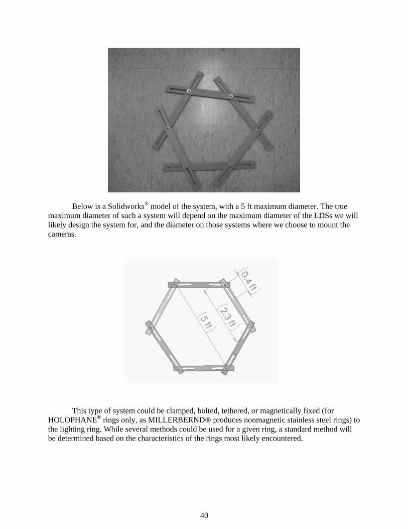
The following picture is a model of the more versatile and simple camera positioning/mounting design developed. A system such as this could be used to both mount the cameras as well as position them at the proper angles. For HOLOPHANE® LDSs, such a system would be mounted below the ring, or on the extension bars for the light, as there is equipment on top of the ring that would prevent it from being mounted there. For MILLERBERND® LDSs, this device could be mounted on top of the ring or on the horizontal light extension bars as in the HOLOPHANE® design. The important features of the model are that it can easily be adjusted to a range of diameters, it can provide the positioning markers, and the cameras can be mounted directly onto it (instead of onto the ring itself). By loosening the bolts, sliding the pieces closer or farther apart, and then tightening the bolts, the diameter can be adjusted to within the full range allowed by the position slots.
The advantage of a system such as this is that it is easily configured to various diameters. Seen above, the system is at maximum diameter. Seen below, the system has been adjusted to accommodate a much smaller diameter.
40
Below is a Solidworks® model of the system, with a 5 ft maximum diameter. The true maximum diameter of such a system will depend on the maximum diameter of the LDSs we will likely design the system for, and the diameter on those systems where we choose to mount the cameras.
This type of system could be clamped, bolted, tethered, or magnetically fixed (for HOLOPHANE® rings only, as MILLERBERND® produces nonmagnetic stainless steel rings) to the lighting ring. While several methods could be used for a given ring, a standard method will be determined based on the characteristics of the rings most likely encountered.

41
APPENDIX C
Specifications Video Cameras
The video cameras we are currently using are the Axis 230 MPEG-2:
• Maximum resolution: 720x480 • Focus: Auto, min. 0 cm focal distance • Pan/tilt/zoom: No pan or tilt, 18x optical zoom • Frame rate: 30 frames/sec at 720x480 resolution • Wireless: Requires 802.11a/b/g Wireless Device Point • Software: Requires Axis Camera Explorer, Camera Recorder, or Milestone (among
others) to remotely manage, control, and view unlimited cameras simultaneously and record streaming video to hard drive simultaneously from several cameras
• Operating temperature, humidity: 41-122 F, 20-80% non-condensing • Power: 9W • Dimensions, weight: 3.2”x3.0”x6.7”, 1.7 lb • Other features: Automatic gain, white balance, and backlight compensation • Price: $1860
Wireless Bridges
The wireless bridges we are currently using are the Netgear WGE101NA:
• 802.11b/g, up to 54Mbps • 10BASE-T/100BASE-T Ethernet Port • Power: 12 VDC, 1.2 A • Price: $80
Wireless Router
The wireless router we are currently using is the Netgear FWAG114NA:
• 802.11g, up to 54Mbps • 4 10/100 Mbps Ethernet ports • Power: 12 VDC, 1.2 A • Price: $290

42
Power Supplies
The power supplies we are currently using are the RoadPro Portable Power Supply:
• Output power capacity: 150W • Nominal output voltage: DC 12V, 3 A-h • Price: $100
Ultrasound Distance Measurement Device
The ultrasound distance measurement device we are currently using is the Sonin Combo Pro 10300:
• Measures up to 250’ using electronic target • Readings displayed in ft/in, decimal ft, meters, or yards • Battery operated • Price: $130
Laptop
The laptop computer we are currently using is the HP zt3170us:
• Processor: Pentium M 1.4GHz • Wireless: 54G LAN and Bluetooth • Display: 15.4” WVA WUXGA • Hard Drive: 80 GB HD • Media Storage: DVD+RW/R&CD-RW • Power: Extra 8-cell battery • Warranty: 1-year express warranty with accidental damage protection • Price: $3065
Software
The video signals are monitored on the laptop using Internet Explorer (Microsoft) and LABVIEW® (National Instruments). The video is saved and simultaneously compressed using Camtasia Studio (TechSmith). Individual image files are extracted from the video using SnagIt (TechSmith). Full video compression is performed using cleaner XL (discreet). Crack measurement is performed using LABVIEW® (National Instruments).

43
APPENDIX D
System Assembly Procedure 1. Assemble ring adaptor around horizontal lighting ring bars. The ring adaptor is held together
at its pivot points by cotter pins. In its closed position, all but one pivot point is connected. To arrange around the lighting ring, the adaptor must be unfolded and the last pivot point attached by connecting the two remaining free ends of the perforated bars with the remaining cotter pin.
2. Attach shape-fixing plates to either side of the pivot points. Because the cotter pins do not
rigidly hold the adaptor ring in a fixed shape, these plates must be used to ensure the ring stays in a hexagon shape. One end of each plate is left attached to each bar by a cotter pin. Once the adaptor ring is resting on the horizontal lighting ring bars, the other end of each plate can be attached with cotter pins. While the cotter pins do not rigidly fix the plates either, the plates ensure a fixed shape because they allow only a very slight change of angle (between each adjacent bar) around each pivot point.
3. Attach the adaptor to the horizontal lighting ring bars via U-bolts. For a three-light system,
there will be three attachment points. Using the centering markers on the bars, the adaptor can be aligned on the lighting ring. When each centering marker on the three (for example) adaptor bars used to attach to the ring, the adaptor is aligned with the lighting ring – both via centerpoints and via rotational angles.
4. Attach the camera modules and the router module to the ring, using the placement markers as
guides to get approximately 120 degree spacing between cameras. Align the camera so its faces squarely the pole, being sure to adjust the height to avoid any obstacles in the sight of the camera.
5. Test the wireless transmission with the laptop to ensure signal quality and strength, and test
the video recording software and video storage to ensure proper operation. 6. Once all tests are complete, full video can be taken.

44

45
APPENDIX E
System Bill of Materials
The following list is an initial compilation of the components and costs of a complete wireless inspection system:
• Axis 230 MPEG-2 wireless auto-focus zoom network camera, 3: $5580 (at $1860
each). Purchased from: http://www.cdw.com • HP zt3170us laptop computer: $3065. Purchased from: http://www.shopping.hp.com • Netgear FWAG114 802.11a/b/g Wireless Router: $290. Purchased from:
http://www.amazon.com • Netgear WAG511 802.11a/b/g Wireless PC Card: $82. Purchased from:
http://www.amazon.com • Netgear WGE101 Wireless Bridge, 3: $240 (at $80 each). Purchased from:
http://www.amazon.com • RoadPro portable power supply, 3: $300 (at $100 each). Purchased from:
http://www.bartswatersports.com • Sonin Combo Pro 10300 ultrasound distance measuring device: $100. Purchased
from: http://www.engineersupply.com • TechSmith’s Camtasia Studio 2: $320. Purchased from: http://www.techsmith.com • TechSmith’s SnagIt: $120. Purchased from: http://www.techsmith.com • Discreet’s cleaner XL: $500. Not purchased (used a trial version, and the project
ended before the trial period ended). • Square perforated steel bars, ¾” x 3 ft. long, 6: $90 (at $15 each). Purchased from:
Lowe’s • Cigarette lighter power adaptors, 4: $40 (at $10 each). Purchased from: Radio Shack • CAT-5 Ethernet cables, 10 ft., 3: $30 (at $10 each). Purchased from: Circuit City • Various nuts, bolts, locking washers, clamps, and tethers for mounting the cameras to
the variable-diameter positioning system, this system to the ring, and the power supply to the ring, as well as necessary tools: Approx. $150
• Various laptop accessories: carrying case, recording media for data storage and distribution (compact discs/DVDs), non-glare screen covering: Approx. $200
The total cost for these components is approximately $11,000. This does not include a
royalty fee that may need to be paid to National Instruments (http://www.ni.com) for the use of LABVIEW® software for future applications.

46

47
APPENDIX F
Brief Overview of the Polecat Robotic Inspection Device
Polecat is a robotic crawler system used for nondestructive evaluation, developed by the Virginia Transportation Research Council (VTRC) and the University of Virginia under research funds provided by the Federal Highway Administration (FHWA) and the VTRC. The overall concept of the robotic system is shown below. The data generated from inspection include video images from an on-board video camera and coordinate locations of the robot on the pole. These data are transmitted to the ground-based computer system for real time viewing and for storing the data on the hard disk for further analyses. Polecat is tethered to a power source on the ground, which in field applications typically includes a portable generator system. The same tethering cable system includes cables for transmission of video data.

48
The electrical system includes a control box on the ground, which is connected to the control software in the laptop computer. Cursor movements on the screen control Polecat. The controls and data acquisition are simplified by standard WINDOWS® -based mouse-operated controls with a Graphical User Interface (GUI). Polecat is equipped with a CCD color camera with a motorized zoom lens control unit. There are two ways to capture the data from the CCD camera: the PC on the ground can capture the picture as bitmap images, and a VCR can record the streaming video as analog data. The possibilities and opportunities for on-site data analyses on the ground-based computer are virtually unlimited.
Extensions of the Polecat technology for structures other than highway high-mast light/camera poles and the adaptation of Polecat for detection of subsurface cracks (requiring ultrasonic sensors) are also possible.