final docu paged
TRANSCRIPT

Design of a Vehicular Collision Automatic Advisory
and Data Management System
A Thesis Project
Presented to the
Faculty of
The Electrical/Electronics
Engineering Department of the
University of San Carlos
Cebu City, Philippines
In Partial Fulfillment
Of the Requirements for the Degree
Bachelor of Science in Electronics Engineering
By
Gerard O. Campomayor
Jelley Gay P. Ceniza
Donna Bel R. Flores
Dexter E. Nuevo
Engr. Jerome M. Puza
Engr. Adrian D. Villarin
Advisers
February 2013

Acknowledgement

Abstract

Approval Sheet

Table of Contents
Title Page
Acknowledgement i
Abstract ii
Approval Sheet iii
Table of Contents iv
List of Figures and Tables vi
Chapter 1 The Problem and Its Settings 1
1.1 Introduction 11.2 Statement of the Problem 21.3 Significance of the Study 31.4 Scope and Limitations
41.5 Definition of Terms 5
Chapter 2 Review of Related Literature 8
1.6 ECall 81.7 Portable Systems 91.8 Single-board Embedded System 111.9 Data logger and Google Maps 12
Chapter 3 Methodology 13
1.10 Project Flow 131.11 System Overview 14
1.12 Client Module 15
1.13 Server Module 211.14 Software Support 251.15 Calibration of ADXL345 291.16 Testing
31

Chapter 4 Results and Discussions 33
1.17 Small-scale In-vehicle Sensor System 131.18 Communication Device Using GPS and GSM/GPRS Module 38
1.19 Receipt and Storage of Data into the Database 41
1.20 Display of Information from Database to Website 421.21 Testing
44
Chapter 5 Summary, Conclusions, and Recommendations 81
1.22 Summary 811.23 Conclusions 811.24 Recommendations 82
Bibliography 84
Appendices
Appendix A – Gantt Chart
Appendix B – Bill of Materials
Appendix C – Client Module Hardware Connections
Appendix D – Module Schematics
Appendix E – Datasheets
Appendix F – Microcontroller Unit Code
Appendix G – ‘Default.php’ Page Code
Appendix H – ‘Acceleration.php’ Page Code
Appendix I – ‘Details.php’ Page Code
Appendix J – ‘Receive.php’ Page Code
Appendix K – ‘Greys.css’ Page Code

Appendix L – Photo Documentation
Curriculum Vitae
List of Tables and Figures
Tables
Table No. Title of Table Page
1.1 Percentage of Vehicular Accidents in 2011 and 2012 1
1.2Records of Road Accident Fatalities and Injuries in
ASEAN Countries 2
4.1Summary of Acceleration of Gravity Measurements before
and after Calibration36
4.2Accelerometer and GPS Information (Latitude and Longitude) at Paseo Arcenas, Banawa, Cebu City
46
4.3Error of Location Information Acquired at Paseo Arcenas,
Banawa, Cebu City47
4.4Time Information Acquired at Paseo Arcenas, Banawa,
Cebu City48
4.5Time Delay of Information Sending through GPRS at
Paseo Arcenas, Banawa, Cebu City49
4.6Time Delay of Information Sending through SMS at Paseo
Arcenas, Banawa, Cebu City49
4.7Accelerometer and GPS Information (Latitude and
Longitude) at Shell Station - Basak, Pardo51
4.8Error of Location Information Acquired at Shell Station -
Basak, Pardo52
4.9 Time Information Acquired at Shell Station - Basak, Pardo 53
4.10Time Delay of Information Sending through GPRS at
Shell Station - Basak, Pardo54
4.11Time Delay of Information Sending through SMS at Shell
Station - Basak, Pardo54
4.12Accelerometer and GPS Information (Latitude and Longitude) at Jollibee - North Reclamation Area
56
4.13 Error of Location Information Acquired at Jollibee -
North Reclamation Area57
4.14Time Information Acquired at Jollibee - North
Reclamation Area58
4.15Time Delay of Information Sending through GPRS at
Jollibee - North Reclamation Area59

4.16Time Delay of Information Sending through SMS at
Jollibee - North Reclamation Area59
4.17Accelerometer and GPS Information (Latitude and
Longitude) at McDonalds - Lapu-Lapu61
4.18 Error of Location Information Acquired at McDonalds -
Lapu-Lapu62
4.19 Time Information Acquired at McDonalds - Lapu-Lapu 63
4.20Time Delay of Information Sending through GPRS at
McDonalds - Lapu-Lapu64
4.21Time Delay of Information Sending through SMS at
McDonalds - Lapu-Lapu64
4.22Accelerometer and GPS Information (Latitude and
Longitude) at Yati, Liloan66
4.23 Error of Location Information Acquired at Yati, Liloan 674.24 Time Information Acquired at Yati, Liloan 68
4.25Time Delay of Information Sending through GPRS at Yati,
Liloan69
4.26Time Delay of Information Sending through SMS at Yati,
Liloan69
4.27Accelerometer and GPS Information (Latitude and
Longitude) at Busay, Top's Entrance, Lahug71
4.28 Error of Location Information Acquired at Busay, Top's
Entrance, Lahug72
4.29Time Information Acquired at Busay, Top's Entrance,
Lahug73
4.30Time Delay of Information Sending through GPRS at
Busay, Top's Entrance, Lahug74
4.31Time Delay of Information Sending through SMS at
Busay, Top's Entrance, Lahug74
4.32Accelerometer and GPS Information (Latitude and
Longitude) at Nice Day Car Wash, Escario76
4.33 Error of Location Information Acquired at Nice Day Car
Wash, Escario77
4.34Time Information Acquired at Nice Day Car Wash,
Escario78
4.35Time Delay of Information Sending through GPRS at Nice
Day Car Wash, Escario79
4.36Time Delay of Information Sending through SMS at Nice
Day Car Wash, Escario79
4.37 Summary of the Performance of the System 80
Figures
Figure Name of Figure Page

No.
1.1Number of Road Fatalities as reported by the Police vs. the
Health Sector 3
1.2Records of Road Accident Fatalities and Injuries in ASEAN
Countries4
2.1 E-Call System Overview 92.2 GPS Based Road Management Architecture 102.3 Smart Phone Based Accident Detection System 102.4 Block Diagram of GPS-GSM Based Tracking System 113.1 Project Flow Chart 133.2 System Block Diagram 143.3 ATMega644 Pin Configuration 153.4 Gizduino+ Board 163.5 ADXL 345 Pin Configurations 163.6 GPS and GPRS/GSM Shields from E-Gizmo 183.7 Microcontroller Unit Program Flow 193.8 Server Code Flow 213.9 Hierarchies of the Website Content and Features 223.1 Process Flow Chart of 'Receive.php' Page Scripts and Codes 233.11 Process Flow Chart of 'Default.php' Page Scripts and Codes 24
3.12cPanel and its supported features: Used in managing the
website25
3.13 phpMyAdmin: Used in managing the Database 263.14 Notepad ++ Used in coding the PHP Pages of the website 27
3.15Arduino Integrated Development Environment used in
Coding the program for the Microcontroller Unit28
3.16FileZilla FTP Used in uploading and downloading files from
and to the website29
3.17 Accelerometer Output Response Vs. Orientation Gravitiy 303.18 Device Prototype for Testing 313.19 Prototype with its LED Indicators 32
4.1Acceleration of Gravity Measurements viewed on the
Arduino Serial Monitor34
4.2Acceleration of Gravity Measurements viewed on the
Arduino Serial Monitor after Calibration36
4.3Dynamic Resultant Acceleration Values viewed on the
Arduino Serial Monitor37
4.4Graph of Dynamic Resultant Acceleration (G) with respect to
Time(ms)37
4.5 GPS Information Viewed on the Arduino Serial Monitor 38
4.6GPS Location Information and Actual Testing Location
plotted on Google Maps39
4.7Communication between Gizduino+ and GSM/GPRS Module
viewed on the Arduino Serial Monitor40
4.8 Text Message Received by the Mobile Phone 41

4.9 Information Logged into the Database 424.1 Information Displayed in the 'default.php' page of the website 434.11 Information Displayed in the 'details.php' page of the website 43
Chapter 1
The Problem and Its Settings
Vehicular collision is one of the major causes of traffic accidents, road fatalities
and external injuries – it is a problem that continues to contribute to the declining
campaign on road safety [1][2][3]. An automatic advisory and data management system
for vehicular collisions has been proposed by the researchers to solve this problem. The
design and implementation of this study will contribute to the improvement of emergency
response and coordination of the relevant agencies. This chapter will give a background
on vehicular collision, present the proposed research problem, and outline the importance
of conducting the proposed study.
1.1 Introduction
Vehicular collision is a conflict between a vehicle and a moving or a stationary
object in such a manner as to exert a relatively strong force on each other for a relatively
short time. It is one of the major causes of external injuries, death and property damage.
In the Philippines, vehicular collision tops the list of external causes of reported injuries.
According to the recent data from the Department of Health, the average percentage of
vehicular collisions that happen in the Philippines is more than fifty-percent of vehicular
accidents[1][2][3].

Table 1.1 Percentage of Vehicular Accidents in 2011 and 2012 [1][2][3]
Period 3rd Quarter of 2011 4th Quarter of 2011 1st Quarter of 2012No. of Reported
Vehicular Accidents
(Percentage)
1,860 (28.5%) 2,589 (31.5%) 3,904(27.7%)
Percentage of Collision Vehicular
Accidents53% 58.1% 63.3%
There are many existing and proposed solutions in order to decrease the
occurrence or fatalities of vehicular collisions – implementation of laws and rules,
development of vehicular safety systems, automatic advisory to authorities, and gathering
of vehicular collision data.
One approach is to use automatic crash notification systems. These systems use
wireless telecommunication technologies, most often GSM or 3G, and Global Positioning
System (GPS) to instantly alert appropriate public safety agencies when a collision occurs
and inform them of the location of the incident. It reduces road fatalities by enabling
faster emergency medical services notification times, and therefore, the earlier provision
of treatment.
Data management systems are also very useful in vehicular collisions solutions by
keeping track of collision events and collecting relevant and accurate data for future
reference and analysis. The stored data could be used to design better safety systems.
1.2 Statement of the Problem
The researchers have recognized the need for an efficient and centralized road
accident data system in the Philippines. The lack of such system in concerned agencies
and companies has been a major hindrance to the improvement of road accident
management. Crash data is gathered and recorded separately resulting to limited and
inconsistent information and underreporting of vehicular collision cases.
The researchers have also recognized the need for an improvement in emergency
response to decrease fatalities in vehicular accidents. Response time of emergency units
and hospitals is known to be crucial in increasing the survival rate of the involved parties
in road accidents.
Thus, this study aimed to provide an automatic advisory to the authorities and
concerned personnel if there is a vehicular collision. The objectives of this study were:
i) To design a small-scale in-vehicle sensor system that will detect collision.
ii) To design a communication device using a GPS module, GSM module and
microcontroller that will send location and time stamp data.
2
iii) To develop a system that will receive data and store it into a database.
iv) To develop a website that will display data from the database.
1.3 Significance of the Study
The time-dependence of trauma from road crashes is well accepted within the
medical literature. A number of studies have also investigated the link between road
trauma fatalities and emergency services response times [4]. The faster the response time,
the less the number of fatalities is. In the Philippines, emergency response is slow
especially in rural areas due to delays in the reporting of the accident and the lack of
advanced communications equipment of the concerned agencies in monitoring the road
situation [5].
Automatic notification of vehicular accidents will improve the response time of
emergency units since it will be able to save crucial time spent on manually trying to
contact the authorities concerned. The automatic transmission of location and other
relevant data will help the emergency units to instantly plan routes, estimate the severity
of the accident and bring the needed equipment. It will also make possible emergency
response in remote areas especially during nighttime where it is unlikely for a witness to
be present.
Another persistent problem in road accident management in the Philippines is that
data gathering of the police and health sectors are not done in a centralized manner.
Because of this, there are inconsistencies and inadequacies in crash data for analysis. This
has also resulted to an underreporting of vehicular accidents to the police authorities as
shown in Figure 1.1 and Table 1.2.
Figure 1.1 Number of Road Fatalities as reported by the Police vs. the Health Sector [6]
3

Table 1.2 Records of Road Accident Fatalities and Injuries in ASEAN Countries [6]
Data on vehicular collisions—location and time of vehicular collision and severity
of collision—should be logged for precaution and for a more organized system of
gathering data by the police and concerned agencies. The detection and systematic
collection of vehicular collision data is essential for all the concerned agencies such as
the Philippine National Police – Traffic Management Group (PNP – TMG), Department
of Public Works and Highways (DPWH) and Department of Health (DOH) because it
can serve as a basis for regulation of new traffic laws, improvement of public roads and a
more convenient data gathering method. This will also help car companies to improve the
safety systems of their vehicles and reduce financial costs by making informed decisions
about the most effective measures to implement to manage risk.
1.4 Scope and Limitations
The study focused on the design of a small-scale prototype that detects collision
and has automatic advisory and data management system. The project was divided into
two major modules: the Client Module and the Server Module. The Client Module
hardware consisted of a microcontroller module with sensor, GSM and GPS shields. The
software consisted of an Arduino program for the microcontroller. The Server Module
4

consisted of a database wherein the location, timestamp and sensor data are stored and a
website to display the data from the database.
The type of sensor that was used in this project is the most common and readily
available in the Philippines. Sensors designed to specifically detect car crash are mostly
manufactured, sold and tested in other countries, therefore the main function of the sensor
module was limited to just triggering the microcontroller to gather data from the sensor
and logging it into the database. The standard threshold used by car security systems in
designing car crash sensors was not used because of the limited range of the sensor that
was used and limited means of testing. Instead, a lower threshold was set in order to
trigger the data gathering function of the microcontroller.
The prototype was designed such that vehicle design and construction, including
the placement of the device inside the vehicle, was hardly considered. The term
“collision” used in this study referred only to impacts beyond the set threshold of the
accelerometer, other factors such as rollover, impact force, and accident setting were
neglected.
The study did not cover crash testing involving actual vehicles because it is highly
expensive and there is no vehicular collision testing facility available in the Philippines.
The study also did not include further cyberspace security of the website other than the
security provided by the web host.
Strength of the device casing was assumed to be significantly high so as to
survive a crash impact. GSM/GPRS signal was assumed to be at an adequate level and
GPS position estimation was assumed to be adequately accurate.
5

1.5 Definition of Terms
Vehicular collision – occurs when a vehicle collides with another vehicle, pedestrian,
animal, road debris, or other stationary obstruction, such as a tree or utility pole. In this
study, it refers to an acceleration value that is beyond the threshold set by the sensor
system.
Sensor system – measures a physical quantity and converts it into a signal which can be
displayed on an instrument and read by a user, and can be programmed to detect changes
in parameters measured.
Global System for Mobile communication (GSM) – a digital mobile telephony system
that uses a variation of time division multiple access (TDMA) and operates at either the
900 MHz or 1800 MHz frequency band.
General Packet Radio Services (GPRS) – a packet-based wireless communication
service based on GSM communication with data rates from 56 up to 114 Kbps.
AT commands – allow giving instructions to GSM devices for operations like calling a
number, sending, reading, or deleting an SMS, setting the SMSC number, looking for a
GPRS access point, reading and deleting phonebook data, reading the battery status,
reading the signal strength, and so on. Different device manufacturers provide an AT
command set guide, where the basic command syntax and the response of the commands
are specified.
Global Positioning System (GPS) – a space-based satellite navigation system that
provides location and time information in all weather, anywhere on or near the Earth,
where there is an unobstructed line of sight to four or more GPS satellites.
6

NMEA – a combined electrical and data specification for communication between
marine electronic devices defined by the U.S.-based National Marine Electronics
Association. It uses a simple ASCII, serial communications protocol that defines how
data is transmitted in a "sentence". The standard also defines the contents of each
sentence type so that the message can be parsed accurately.
Data Management - is an administrative process by which the required data is acquired,
validated, stored, protected, and processed, and by which its accessibility, reliability, and
timeliness is ensured to satisfy the needs of the data users.
Web server – software that delivers Web content that can be accessed through the
Internet and is able to host websites and data storage. Using the Hypertext Transfer
Protocol (HTTP). HTML documents and any additional content that may be included by
a document, such as images, style sheets and scripts are delivered on the request to
clients.
Database – is a systematically organized or structured storage of information that allows
easy retrieval, updating, analysis, and output of data.
PHP – a widely-used general-purpose scripting language that is especially suited for Web
development and can be embedded into HTML.
7

Chapter 2
Review of Related Literature
In-vehicle emergency and security systems have become a necessity and an
advantage to car manufacturing companies ever since its development in early 2000s.
Most of these systems are equipped with communication services that aimed to provide
the automatic notification of a road traffic accident through GSM and GPS-based
positioning. This chapter will present different studies that are related to the proposed
research study and the methods they used in order to achieve their objectives. The
different advantages and disadvantages of the studies presented will also be discussed in
this chapter.
2.1ECall
Filjar, Vidovic, Britvic, and Rimac [7] presented the architecture and technical
solution of the modem-based eCall. ECall refers to an in-vehicle telecom service
expected to be introduced and operated across Europe on 2015. The introduction and use
of in-vehicle eCall for deployment of emergency assistance is expected to save lives and
reduce social burden by improving the notification of road accidents and speeding up
emergency service response [7]. The eCall device consists of in-vehicle control unit with
a GPS receiver and GSM connected to the car sensors. It triggers an emergency call upon
the detection of an accident or by manual interaction of the user and sends Minimum Set
of Data (MSD) containing the timestamp and geographical position of the accident,
activation indicator (manual or automatic), and vehicle type and identification number,
number of passengers.
8

Figure 2.1 eCall System Overview [7]
A disadvantage of this system is that the device is installed upon manufacture,
making the device (1) proprietary of the carmakers, which renders it difficult to use the
technology for the public’s optimum benefit; and, (2) unavailable in all vehicles,
especially those that was manufactured before the technology was developed. Moreover,
the system utilizes one of the vehicle’s pyrotechnic systems like the airbag or seatbelt
tensioning system, making the system expensive.
2.2 Portable Systems
A study by Pinart, Calvo, Nicholson, and Villaverde [8] presented an early crash
notification system that was dedicated to two-wheeled and secondhand vehicles. The
system has two major modules in its system, the accelerometer which was chosen as the
crash sensor and the eCall box – a communications enabled device which encompasses
GSM and Short-Range Communications (SRC). The connection between the crash sensor
and eCall box can be wired or wireless and its wireless connection was tested to be viable
in a worst-case scenario in terms of Bluetooth link quality and reliable in case of long
duration and crash detection. This service, however, requires a vehicle’s on-board or
portable computer for sending the crash data to emergency services, which is absent in
older vehicles and expensive to install.
Goh, Ng, Jusoff, Chen, and Tan [9] conducted a study on a GPS-based approach
for reporting thoroughfare problems such as malfunctioning traffic lights, potholes and
roads in bad condition via GSM. They used a GPS-supported GSM phone and Python
script to retrieve GPS signals and send SMS to server.
9
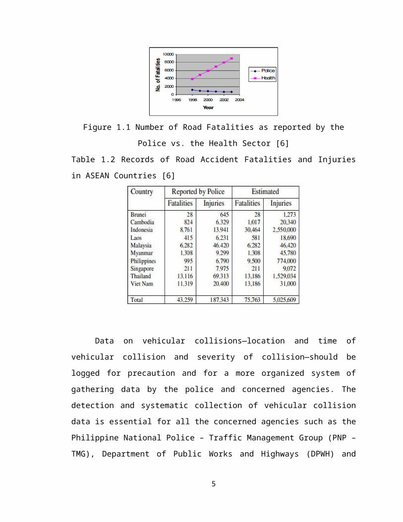
Figure 2.2 GPS - Based Road Management System Architecture [9]
A study by White, Thompson, Turner, Dougherty, and Schmidt [10] describes
how smartphones, such as the iPhone and phones that have Google Android platforms,
can automatically detect traffic accidents with their built-in sensors, immediately notify a
central emergency dispatch server after an accident, and provide situational awareness
through photographs, GPS coordinates, Voice over Internet Protocol (VOIP),
communication channels, and accident data recording.
Figure 2.3 SmartPhone-Based Accident Detection System [10]
10

Smartphone-based accident detection applications have both advantages and
disadvantages relative to conventional in-vehicle accident detection systems, e.g., they
are vehicle-independent, increasingly pervasive, and provide rich data for accident
analysis, including pictures and videos. Building a smartphone-based accident detection
system is hard, however, because phones can be dropped and generate false positives and
the phone is not directly connected to the vehicle so their motions do not directly mirror
the forces the vehicle experiences. In-vehicle accelerometers, on the other hand, are
physically mounted to the car, making them more reliable in detecting traffic accidents.
2.3 Single-board Embedded System
A study by Khan and Mishra [11] used a single-board embedded system that is
equipped with GPS and GSM modems along with ARM processor that is installed in the
vehicle, making the device portable, more compact, less costly, and specifically designed
for its function. The basic function of in-vehicle unit is to acquire, monitor and transmit
the position latitude, longitude, time to management center either at fixed interval or on
demand. Microcontroller unit serves as the heart of tracking unit, which acquires and
process the position data from the GPS module and sends the data to the management
center through the GSM Modem.
Figure 2.4 Block Diagram of GPS-GSM Based Tracking System [11]
11

2.4 Data logger and Google Maps
In the study by Goh, Ng, Jusoff, Chen, and Tan [9], the SMS server at receiver’s
side transfers data to local computer database. The system optimizes location, date and
time data by mapping the site onto Google maps using PHP scripts.
The study by White, Thompson, Turner, Dougherty, and Schmidt [10] is an
internet-based service that depends entirely on freely-available Application Program
Interfaces (APIs) and open-source software. The program for retrieving in storing data
information coded using Java language. It utilizes a MySQL database to store accident
information. The server communicates with the clients using custom Extensible Mark Up
Language (XML) for the Android application and JavaScript Object Nation (JSON) for
the web-based application. When an accident occurs, it is geo-tagged on the server with
its location and entered into a searchable database of accidents. The accident locations are
shown in a map through a Google Maps interface.
12

Chapter 3
Methodology
This study is a design-demonstration research of an automatic advisory and data
management system for vehicular collisions. Project construction consisted of: (1)
hardware design and implementation of a microcontroller unit equipped with sensor,
GPS, and GSM shields, (2) coding of the program for the microcontroller unit for alarm
sensing, location and time data gathering, and data sending, (3) coding of the program for
an online database and website for data storage and display. This chapter will present the
materials and methods that were used in the construction, testing, and evaluation of the
system in study.
3.1 Project Flow
The following flow chart maps out the entire process to finish the project within
the allotted time.
Figure 3.1 Project Flowchart
13

3.2 System Overview
The automatic detection of a collision is achieved by constantly monitoring the
output of the sensor, which in this study is the acceleration data from an accelerometer.
The microcontroller checks x-axis, y-axis and z-axis output data for sharp spikes in the
resultant acceleration values. If a peak above a certain threshold is found, the alarm
becomes active. The microcontroller extracts this peak acceleration data by accessing the
appropriate registers on the accelerometer.
The GPS module constantly outputs NMEA sentences containing location,
altitude, and other data. At the instant the alarm becomes active; the microcontroller
extracts time and location data from the GPS module. The microcontroller uses AT
commands to establish wireless communication and send the acceleration and GPS data
to a server through General Packet Radio Service (GPRS), a packet oriented mobile data
service on the 2G and 3G networks, and to mobile phones through Global System for
Mobile Communications (GSM). The server stores the received data on a database and
displays it on a webpage.
14
Server Module
Client Module

Figure 3.2 System Block Diagram
The system is composed mainly of the Client Module and the Server Module. The
Client Module consists of the in-vehicle device and was implemented using E-Gizmo’s
ADXL345 3-Axis Digital Accelerometer board, ATmega644 GizDuino+, SIM900D
GSM/GPRS Module and GPS Module. The Server Module is made up of a website
hosted by an online server that supports MySQL, PHP and is accessible in the domain,
sirena1234.vacau.com
3.3 Client Module
3.3.1 Hardware of Client Module
3.3.1.1 Gizduino +
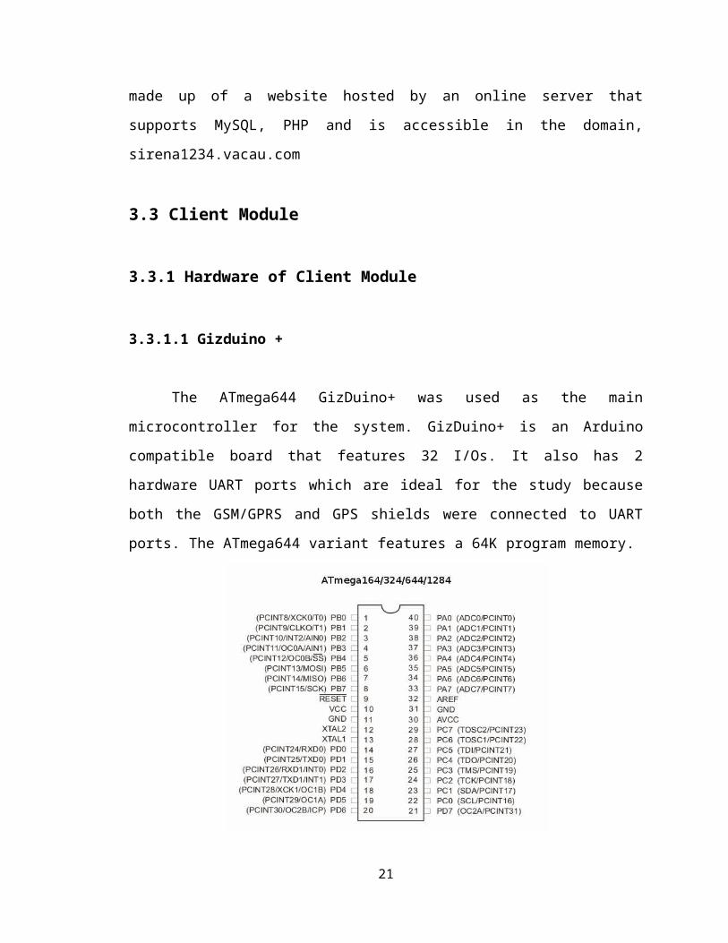
The ATmega644 GizDuino+ was used as the main microcontroller for the system.
GizDuino+ is an Arduino compatible board that features 32 I/Os. It also has 2 hardware
UART ports which are ideal for the study because both the GSM/GPRS and GPS shields
were connected to UART ports. The ATmega644 variant features a 64K program
memory.
Figure 3.3 ATmega644 Pin Configurations [13]
15

The ATmega644 is a low-power CMOS 8-bit microcontroller based on the AVR
enhanced Reduced Instruction Set Computer (RISC) architecture. The ATmega series of
microcontrollers are created by Atmel and are currently used by the Arduino platform.
They feature general-purpose I/O ports, internal self-programmable instruction flash
memory, and a variety of serial interfaces.
Fig 3.4 Gizduino+ Board
3.3.1.2 ADXL345: A 3-Axis, ±2 g/±4 g/±8 g/±16 g Digital Accelerometer
Accelerometers measure the rapid deceleration of a vehicle on hitting an object.
They are the most widely used sensors in the automotive sector, especially in airbag
deployment.
Figure 3.5 ADXL345 Pin Configurations [12]
16

The ADXL345 was used as the sensor for the system. It is a small, thin, low
power, 3-axis accelerometer with high resolution (13-bit) measurement at up to ±16 g.
Digital output data is formatted as 16-bit twos complement and is accessible through
either a SPI (3- or 4-wire) or I2C digital interface [12].
An ADXL345 breakout board designed by E-Gizmo was used in this study. The
ADXL345 breakout board was connected to the Gizduino using SPI communication
protocol.
3.3.1.3 GPS and GSM Shield
The SIM900D GSM/GPRS module was used for the transmission of data.
SIM900D is a quad-band GSM/GPRS engine that works on frequencies GSM 850MHz,
EGSM 900MHz and PCS 1900MHz. It features GPRS multi-slot class 10/class 8 and
supports the GPRS coding schemes Coding Scheme-1, Coding Scheme-2, Coding
Scheme-3 and Coding Scheme-4.
A Smart Buddy SIM card from Smart Communications, Inc., with its data
services activated, was used for the GSM/GPRS module.
The SkyNav EG25A1 GPS module was used for the gathering of time and
location information. The GPS signal is applied to the antenna input of module, and a
complete serial data message with position, velocity and time information is presented at
the serial interface with NMEA protocol.
E-Gizmo’s GSM/GPRS Module and GPS Module are specially designed to
function as GizDuino shields. They were mounted directly on the GizDuino board.
17

(a) GSM/GPRS shield
(b) GPS shield
Figure 3.6 GPS and GSM/GPRS Shields from e-Gizmo
3.3.1.4 Power Supply
The modules used in this study had a single power supply which is two (2) 4V
lead-acid batteries in series. The supply voltage is regulated by regulators within each
module.
3.3.1.5 LED Indicators
Six (6) light-emitting diodes (LEDs) were used to display the functions of the
client module as they are being executed. They were connected to the digital output pins
18

of the modules. LED1 and LED2 indicate the initialization of the GPRS function of the
GSM/GPRS module. LED1 lights up when the module is attached to GPRS service.
LED2 lights up when wireless connection with GPRS is established. LED3 and LED4
indicate the sensing function of the client module using the ADXL345. LED3 lights up
when the microcontroller starts reading and processing acceleration values from the
sensor. LED4 lights up when the threshold acceleration value has been exceeded and the
collision alarm becomes active. LED5 and LED6 indicate the transmission of data. LED5
lights up when all the necessary information, specifically, peak acceleration, time, and
location, has been gathered and the data has been sent to the remote server. LED6 lights
up when the same information has been sent to the mobile phone through SMS.
3.3.2 Coding of Program for the Microcontroller Unit of Client Module
Figure 3.7 Microcontroller Unit Program Flow
19

The microcontroller unit was developed using Arduino. Arduino is an open source
physical computing platform based on a simple input/output (I/O) board and a
development environment that implements the processing language.
The program for the ATmega644 microcontroller was coded using the Arduino
language and Arduino IDE. The program executes as follows:
Communication with the GSM/GPRS module is established at a baud rate of
57600, utilizing the primary hardware UART port of the Gizduino. GPRS function is
initialized by using AT commands, followed by carriage return and newline, to attach
GPRS service, set GPRS as wireless connection mode, set TCP local port, set single IP
connection, start task and set APN for Smart Buddy (“internet”), bring up wireless
connection, get local IP address, disable IP header, and configure primary
(“208.67.222.222”) and secondary (“208.67.220.220”) domain name servers. LED1 and
LED2 light up.
SPI Communication with ADXL345 is established. LED3 lights up. The
ADXL345 is put into +/- 4G range and into measurement mode by writing to the
appropriate registers. x, y and z acceleration values are retrieved by reading data from the
appropriate registers and converting them to units of G. The resultant acceleration is then
calculated.
The said registers are continued to be read until the specified resultant
acceleration threshold is exceeded. In this case, the sensor alarm is considered to be
active. LED4 lights up.
Communication with the GPS module is then established at a baud rate of 9600,
utilizing the secondary hardware UART port of the Gizduino. The GPGGA sentence was
chosen as the source for the time and position information. This sentence refers to the
Global Positioning System Fixed Data. The Arduino code searches for the GPGGA
string: $GPGGA, hhmmss.sss (UTC time), ddmm.mmmm (latitude), N (S),
dddmm.mmmm (longitude), E (W)… The time, latitude, and longitude were extracted
from the GPGGA string. UTC time is converted to Philippine local time by adding 8
hours.
The time, position, and acceleration information is then prepared for sending
through GPRS and SMS. To send through GPRS, TCP connection is started using AT
20

commands. Domain name and port are set, in this case “sirena1234.vacau.com” and “80”
respectively, and data is sent via URL. LED5 lights up when the Arduino receives a reply
from the GSM/GPRS module indicating that the data was sent successfully. To send
through SMS, the SMS system is set to text mode, the mobile phone number of the
recipient is set, and text message containing the time, position, and acceleration is sent.
LED6 lights up when the Arduino receives a reply from the GSM/GPRS module
indicating that the text message was sent successfully.
The code was uploaded to the microcontroller by connecting the GizDuino board
to the computer via USB cable.
3.4 Server Module
Figure 3.8 Server Module Program Flow
The server module is made up of a website hosted by a server which supports
PHP Scripts and MYSQL Database. This website is acquired through free webhosting
service – a type of internet hosting service which makes websites accessible in the World
Wide Web through its free available domains. A website from 000webhost was acquired
with the domain http://sirena1234.vacau.com, equipped with 1500 MB disk space,
cPanel, PHP and MySQL support, and File Transfer Protocol Support. The control panel
provided by 000webhost also utilizes the use of phpMyAdmin in administrating MySQL
databases.
21

Figure 3.9 Hierarchies of the Website Contents and Features
Upon the acquisition of website, a database was created using phpMyAdmin. The
database name was set to ‘a6705968_oink’ and the table name was set to ‘arduino’.
MySQL makes use of tables which contain rows and columns for storing or logging
information from the data transmitted by the client module. Five columns in the ‘arduino’
table was created – the date column, which contains the date and timestamp upon receipt
of the transmitted data of the client module; the acceleration column, which contains the
values of acceleration transmitted by the client module; the time column, which contains
the timestamp of the collision – this timestamp is acquired from the GPS shield unlike the
22
000Webhost
Domain: sirena1234.vacau.com
Cascading Style Sheet
Support
Contains all HTML the
customizations of the page
PHP Scripts Support
Contains all the basic scripts needed for
connecting to the database, creating and customizing
pages
phpMyAdmin
Used for manipulating the database using
the browser
MYSQL Database
Database Name: 'a6705968_oink'
Table Name: 'arduino'
Arduino Columns: Acceleration, Time, Date, X-coordinates, Y-Coordinates,
Plate Number

other timestamp in the time column, wherein it is acquired from the database’s server; the
plate column, which contains the plate numbers or any identification of the client module;
the coorX and coorY columns , which contains the x-coordinates and y-coordinates
gathered from the GPS shield of the client module.
3.4.1 Receipt, Parsing and Writing of Data into the Database
Figure 3.10 Process Flow Chart of ‘receive.php’ Page Scripts and Codes
After the database and its important columns have been set, several samples of
data were inserted into the table via url method. This was done by coding and uploading a
‘receive.php’ page into the website’s server. The ‘receive.php’ page containing a PHP
script utilizes the ‘mysql_connect()function’ – a PHP function that establishes a
connection with the database and the page. Another script is coded into the page – the
PHP Get Method script which strips out the data transmitted by the client module URL
and logs it into the database. In summary, the ‘receive.php’ page executes the first three
blocks of the Server Module’s program flow.
23
Load/Access 'receive.php' page
Load all PHP Scripts within the page
Fetch the data entered via the URL
Establish connection into the 'a6705968_oink' database
Establish connection with 'a670968_oink' database's
'arduino table'
Log the fetched data into the 'arduino'
table
Return an "OK" message to confirm the logging of data

3.4.2 Display of Data into Webpage
Figure 3.11 Process Flow Chart of ‘default.php’ Page Scripts and Codes
Subsequently, another php page named ‘default.php’ was created to display the
data acquired from the ‘arduino’ table of the ‘ac670968_oink’ database. The
‘default.php’ page serves as the home page and links all other pages within the website.
There are two major scripts coded in the ‘default.php’ page – the Google Maps java script
and the PHP script which establishes the connection to the database and displays the table
with all the values logged into the database.
The Google Maps java script employs the web mapping service application
provided by Google. The java script embeds the Google Map in the page and displays a
marker on an exact location, specified by the coordinates entered in the ‘arduino’ table.
The PHP script in the ‘default.php’ makes use of the ‘mysql_connect()’ function
to connect into the database, ‘mysql_query()’ function to fetch data from the database and
the ‘echo()’ syntax in displaying the data. A checkbox is utilized in order to display the
markers which serve as the indicators of the location of the accident. Checking the
checkbox prompts markers to appear in the embedded map. The table displayed in the
website is customized in a way that it displays the most recent data logged and each
accident is classified according to its severity. There are three severities of accident
24
Load or access the 'default.php' Page
Load all the Java Script, PHP Script and CSS
Load and run the Google Maps Javascript
Establish connection to the database
Display the data from the database into the
page
Run the pagination and autorefresh scripts

classified in the page – Light (for accidents with peak accelerations less than 3g),
Moderate (for accidents with peak accelerations greater than or equal to 3g but less than
8g) and Very Severe (for accidents with peak accelerations greater than or equal to 8g).
A pagination script was also embedded in the page – this was done to prevent the
overflow of table rows in the page. An auto refresh script was also included so that the
page is always updated in case new data is logged into the database. And in order to
improve the appearance and order of the website, it was customized with the use of
HTML tags and cascaded style sheets. The ‘details.php’ page was also coded and
uploaded so that the viewers can opt to see the specific details and larger scale of the map
if a specific accident is viewed. Another page named ‘acceleration.php’ is also coded and
added, and accessing this page gives the option to sort the accidents logged according to
its severity.
3.5 Software Support
Various open-source and free software were utilized in coding and managing the
programs for both the client and server modules.
Figure 3.12 cPanel and its Supported Features: Used in Managing the Website
25
Cpanel is one of the features included in 000webhost’s free hosting service – it is
a web hosting control panel that provides the user a graphical interface in managing the
process of hosting a website.
Figure 3.13 phpMyAdmin: Used in Managing the Database including Creating Tables,
Columns and Managing Stored Information
PhpMyAdmin is a free and open source-tool written in PHP and also
automatically installed in 000webhost’s websites. It provides convenience to users by
using the web browser instead of MySQL commands in managing the database.
26

Figure 3.14 Notepad ++: Used in Coding the PHP pages of the Website
Notepad ++ was used in editing the PHP pages because it is very convenient and
helpful in linking PHP functions and java scripts. It also supports tabbed editing – a
feature where you can edit multiple pages at once. It was also used in coding the style
sheet of the website.
27
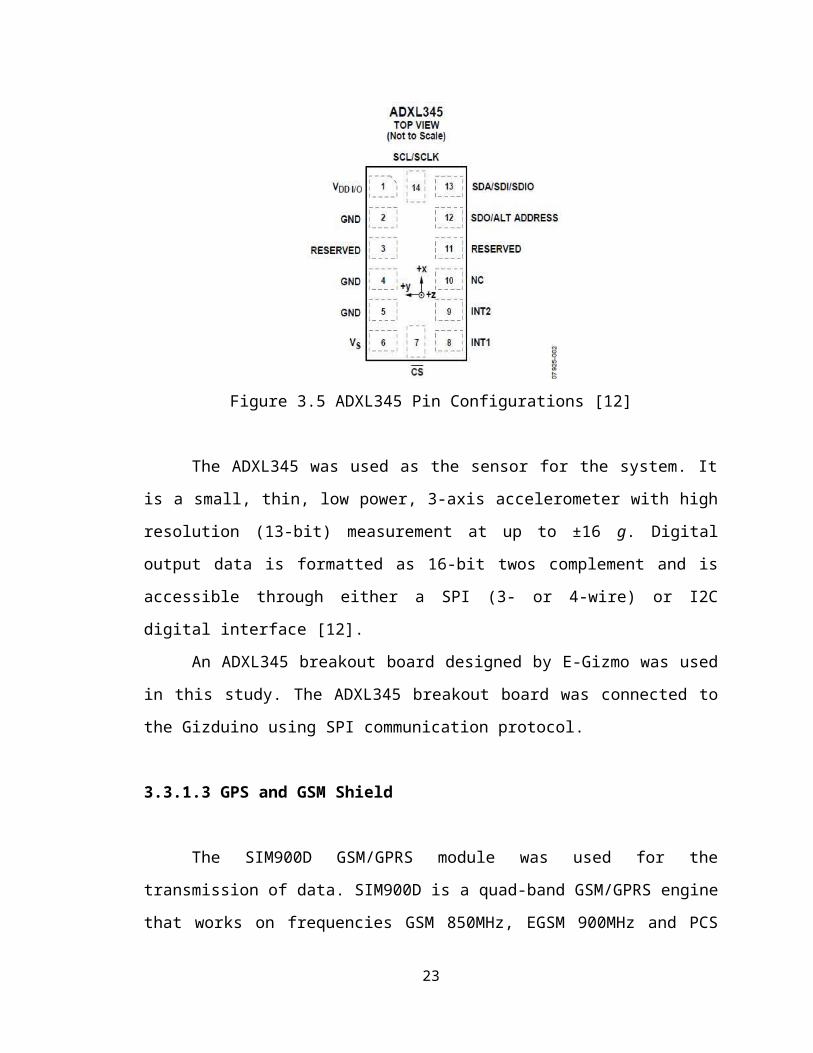
Figure 3.15 Arduino Integrated Development Environment – Used in Coding the
Program for the MCU
Arduino IDE is the most commonly used application in coding Arduino programs.
It was used in compiling and uploading the programs to the microcontroller unit and also
in monitoring the serial ports of the microcontroller.
28

Figure 3.16 Filezilla FTP Client is used in uploading and downloading files from and to
the website
Filezilla was used as the file transfer protocol software because it is available in
the internet and can be downloaded for free.
3.6 Calibration of ADXL345
Accelerometers are mechanical structures which contain elements that move
freely and these elements can be sensitive to mechanical stress. The 0g bias or offset of
an accelerometer defines the baseline for measuring the acceleration. The offset error of
an accelerometer is constant value in g that cancels out the error caused by different
factors – environment, application, soldering and mounting.
29

Figure 3.17 Accelerometer Output Response vs. Orientation to Gravity [12]
Calibration was done by measuring two points per axis, +1g field and -1g field
and by calculating the AOFF using two points per axis [15]. Each axis was oriented into
+1g and – 1g field and their actual measured value were as follows when broken down
into an equation:
A+1g = AOFF + (1g × Gain) (Equation 3.1)
A−1g = AOFF – (1g × Gain) (Equation 3.2)
where:
AOFF is the offset error, in g.
A+1g is the actual measured value of the axis in g if it is oriented at +1g field.
A−1g is the actual measured value of the axis in g if it is oriented at -1g field.
After both values were obtained, AOFF and Gain were calculated using the
following equations:
AOFF = 0.5 × (A+1g + A−1g) (Equation 3.3)
Gain = 0.5 x (A+1g−A−1 g
1 g) (Equation 3.4)
Once the accelerometer’s offset error were obtained, the actual acceleration
became obtainable using the equation:
AACTUAL(x,y,z) = (AOUT−AOFF
Gain) (Equation 3.5)
30

where:
AACTUAL(x,y,z) is the actual acceleration acting on the accelerometer and the desired
value in g.
AOUT is the acceleration read by the accelerometer.
AOFF is the accelerometer’s offset error.
After calibration, the program for the microcontroller unit was modified so that
the acceleration information that is processed by the microcontroller for sensing and
sending is AACTUAL(x,y,z).
3.7 Testing
Since the device cannot be tested using an actual crash, another method in testing
was used. The device was mounted on a model car and was subjected to different crash
tests to record and analyze the performance of the device in terms of: failure in sending
through GPRS and/or SMS, time elapsed between sending and receiving, and errors in
time and position information received.
Figure 3.18 Device Prototype for Testing
The device was tested in seven different locations in Cebu namely, Paseo Arcenas
in Banawa, Shell Gas Station in Basak, Pardo, Jollibee North Reclamation, McDonald’s
Lapu-lapu, Yati, Liloan, Nice Day Car Wash in Escario, and Busay, Cebu. Certain
environmental factors and physical obstructions such as the existence of large
infrastructures surrounding the area were considered. The signal level and the type of
31

connection (EDGE/3G) of the service provider in the locations were checked using a
mobile phone of the same provider. The weather and atmospheric conditions and time of
testing were considered as well.
Figure 3.19 Prototype with its LED Indicators
At the instant the device is turned on, LED1 and LED2 automatically lights up,
indicating the initialization of the GPRS function of the GSM/GPRS module. LED3
lights up when the microcontroller starts reading and processing acceleration values from
the sensor. The car model where the device is installed was subjected to a force enough to
make LED4 light up. When LED4 lights up, signaling the detection of a crash by the
microcontroller, the device is expected to send through GPRS and SMS the information
of the crash: the location of the crash, the timestamp data, and the magnitude of
acceleration. LED5 and LED6 are expected to light up in sequence. Failure of LED5 to
light up indicates failure in sending of the GPRS data. Failure of LED6 to light up
indicates failure in sending of the SMS text message.
The information sent through GPRS will be received by the server and will be
displayed on the website. The information sent as text message through SMS will be
received by a mobile phone. The time of receipt of the data by the database and the text
message by the recipient mobile station were recorded.
Since Google Maps is the most popular choice among developers as web mapping
service for websites, Google Maps coordinates for the said locations were acquired and
compared to the position coordinates displayed on the website.
32

Chapter 4
Results and Discussions
This study aimed to provide an automatic advisory to the authorities and
concerned personnel if there is a vehicular collision. An in-vehicle device was
constructed to perform sensing, processing and communication functions. The device was
tested for performance based on different factors. This chapter presents the findings and
our analysis of the findings. Table of the important results are shown and observed trends
are discussed. The percentage error is calculated to determine the accuracy and reliability
of the device. The possible sources of error are explained.
4.1 Small-scale In-vehicle Sensor System
This study used the 3-axis digital accelerometer ADXL345 as sensor. To test the
basic function of the sensor, the static acceleration of gravity was measured and the
measurements were displayed to the Arduino serial monitor. The results are shown on
Figure 4.1.
(a) X-Axis Oriented into -1G and +1G Fields
33

(b) Y-Axis Oriented into -1G and +1G Field
(c) Z-Axis Oriented into -1G and +1G Fields
Figure 4.1 Acceleration of Gravity Measurements viewed on the Arduino Serial Monitor
Figure 4.1 shows that the measured value of the x-axis in units of G when
oriented at the -1G field is 0.43 and when oriented at the +G field is 0.52. The measured
value of the y-axis when oriented at the –G field is 0.41 and at the +G field is 0.5. The
measured value of the z-axis when oriented at the –G field is 0.51 and at the +G field is
0.48. Using Equations 3.3 and 3.4, the offset acceleration and gain were calculated for
each axis.
34

The accelerometer’s offset acceleration at the x-axis was computed to be 0.475G,
at the y-axis 0.455G, and at the z-axis 0.495G. The gain was computed to be 0.045 at the
x-axis, 0.045 at the y-axis, and 0.015 at the z-axis. By using Equation 3.5 and the
computed offset error and gain, the actual acceleration acting on the accelerometer can be
determined.
The code of the program for extracting accelerometer data was modified in such a
way that the computed offset error, gain and equation 3.5 was embedded to the program
and used in obtaining the actual resultant acceleration of the accelerometer. Figure 4.2
shows the reading of the different axes of the accelerometer after calibration.
(a) X-Axis Oriented into -1G and +1G Fields
(b) Y-Axis Oriented into -1G and +1G Fields
35

(c) Z-Axis Oriented into -1G and +1G Fields
Figure 4.2 Acceleration of Gravity Measurements viewed on the Arduino Serial Monitor
after Calibration
Table 4.1 Summary of Acceleration of Gravity Measurements before and after Calibration
Axis Before Calibration After Calibration+1G Field -1G Field +1G Field -1G Field
X-Axis 0.43 0.52 0.94 0.97Y-Axis 0.41 0.51 1.1 1.07Z-Axis 0.51 0.48 1.02 1.06
As seen on Table 1.1, the values of acceleration of each axis are now closer to its
ideal acceleration, 1G and -1G when projected to +1G and -1G fields, respectively.
An ideal value of 1G in each axis could not be obtained due to external factors
which cannot be controlled, such as the testing environment and vibrations surrounding
the accelerometer – these factors are already out of the scope of the study.
To test the sensing function of the sensor, the model car where the device was
mounted was subjected to a crash test to record and plot the resultant acceleration with
respect to discrete time. An Arduino code was uploaded to the microcontroller that
measures the acceleration of the 3 axes and calculates the resultant acceleration every
approximately 150 milliseconds. Figure 4.3 shows the resultant acceleration
measurements in units of G as shown on the Arduino serial monitor. Figure 4.4 displays
the graph of acceleration versus time.
36

Figure 4.3 Dynamic Resultant Acceleration Values viewed on the Arduino Serial Monitor
0 500 1000 1500 2000 2500 3000 35000
0.20.40.60.8
11.21.41.61.8
0
0.470.470.470.470.480.560.55
1.65
0.130.26
0.390000000000001
0.480.490.450.460.470.470.470.470.47
Graph of Resultant Acceleration vs Time
Time (in mS)
Res
ulta
nt A
ccel
erat
ion
(in
G)
Figure 4.4 Graph of Dynamic Resultant Acceleration (G) with respect to Time (150ms)
37

Figure 4.3 and 4.4 shows that there is a sudden spike in the resultant acceleration
from the accelerometer measured values. This indicates the sudden impact or deceleration
(+/- signs are ignored by the Arduino code) experienced by the model car. The sensor
was able to measure a constant acceleration of 0.47G prior to and after the impact. The
peak acceleration due to the sudden collision was measured to be 1.65G.
4.2 Communication Device using GPS and GSM/GPRS module
A code was uploaded to the microcontroller to extract location and time
information from the GPS module. The Arduino serial monitor was used to view the
GPGGA sentence outputted by the GPS module, and the latitude and longitude and time
information extracted from the GPGGA sentence.
Figure 4.5 GPS Information viewed on the Arduino Serial Monitor
38

Figure 4.5 shows that the GPGGA sentence contained the UTC time 061800.000
in the format hhmmss.sss, the latitude 1021.3075 in the format ddmm.mmmm, the N/S
indicator N, the longitude 12354.8291 in the format dddmm.mmmm, and the E/W
indicator E. The Arduino code was able to process the information so as to obtain the
location coordinates 10.3551N 123.9138E and the local time in 24-hour format 14:18:00
from the GPS module. The geographic coordinates of the actual location of the device
was obtained from Google Maps. This resulted to the actual location having the
coordinates 10.35507N 123.914073E.
The location information obtained from the GPS module and the actual location
were plotted on Google Maps (using green markers) as shown on Figure 4.6. The
distance between the coordinates obtained from the GPS module and the actual
coordinates was calculated to be 30.05 meters. The time information obtained from the
GPS module, however were exactly the same as that of the computer time synchronized
with ‘time.windows.com’.
Figure 4.6 GPS Location Information and Actual Testing Location plotted on Google
Maps
39

The GSM/GPRS module function of sending information from the Client Module
through SMS and GPRS was tested by uploading a code to the microcontroller that sends
pre-defined acceleration, longitude, latitude, and time values. Figure 4.6 shows the
communication between the microcontroller and the GSM/GPRS module using AT
commands. Also shown are the pre-defined values for acceleration, longitude, latitude,
and time.
Figure 4.7 Communication between Gizduino+ and GSM/GPRS Module viewed on the
Arduino Serial Monitor
40

As shown on Figure 4.7, the GSM/GPRS module replied OK to the series of AT
commands sent by the microcontroller. The AT+CIPSEND command sends the data to
the TCP connection and was given the reply SEND OK indicating that the data was sent
successfully. The AT+CMGS command sends the SMS message and was given the reply
OK indicating that the text message was sent successfully.
A mobile number was set in the Arduino code, directing to the mobile phone to
which the text message will be sent. Figure 4.8 displays the mobile phone’s screen
containing the text message received from the GSM/GPRS module.
Figure 4.8 Text Message Received by Mobile Phone
Figure 4.8 shows that the mobile phone received the acceleration value 3G,
longitude 123.5555E, latitude 10.1010N, and UTC time 091521. This is the exact same
information pre-defined and sent by the Client Module (see Figure 4.7).
4.3 Receipt and Storage of Data into the Database
To verify whether the transmitted data by the Client Module is the same as the
received and stored data into the database, these values were pre-defined and sent from
the Client Module (see Figure 4.7):
Acceleration: 3G
Longitude: 123.5555E
Latitude: 10.1010N
Time (in UTC): 091521
41

The information sent by the microcontroller was received by the server through a
PHP page entitled ‘receive.php’. This page acquires data from the microcontroller with
the use of PHP functions. Some of the PHP functions employed are the exclusion of letter
characters to be logged in the ‘acceleration’ field of the database; it was already assumed
that all information logged in this field is in the unit of G and the conversion of the GMT
time to GMT+8 time; all logged information in the ‘time2’ field is already in GMT+8
settings. The expected information logged into the database is seen below while the
actual information logged in the database is seen on Figure 4.9.
Acceleration: 3
Longitude: 123.5555E
Latitude: 10.1010N
Time (in GMT+8): 171521
Figure 4.9 Information Logged into the Database
The same information sent by the microcontroller as viewed in the serial monitor
is logged into the database. The ‘Date’ field of the database is a timestamp of the
information logged – it specifies the date and time the information was logged. It is
extracted from the timestamp of the server and is at GMT-5 time zone.
4.4 Display of Information from Database to Website
The information logged into the database was displayed on the website –
http://sirena1234.vacau.com. The information was displayed through ‘default.php’ page
and ‘details.php’. To verify whether the same information logged on the database is also
the same information displayed on the website, Figures 4.10 and 4.11 are compared.
42

Figure 4.10 Information Displayed in the ‘default.php’ Page of the Website
Figure 4.11 Information Displayed in the ‘details.php’ Page of the Website
The information logged in the database as seen on Figure 4.7 is the same as the
data displayed on the ‘default.php’ (see Figure 4.10) and ‘details.php’ (see Figure 4.11)
page of the website. The time of collision was also set in a 24-hour format and the
logging date & time of the information was already set to GMT+8 time zones.
43

4.5 Testing
The device was subjected to 10 trials each of crash tests in 7 different locations
around Metro Cebu. The information sent through GPRS was displayed on the
http://sirena1234.vacau.com website. The information sent as text message through SMS
were received by the mobile phone of one of the researchers.
Tables 4.2, 4.3, 4.4, 4.5 and 4.6 show the crash test information displayed on the
website and received by the mobile phone at Paseo Arcenas, Banawa, Cebu City. On 9
out of the 10 trials (90%), the device was able to send the GPRS data successfully. On 10
out of the 10 trials (100%), the device was able to send the SMS text message
successfully. Out of the 9 data successfully sent, none (0%) included erroneous
information. Out of the 10 text messages successfully sent, none (0%) included erroneous
information.
Table 4.2 shows the information which includes the plate number, the magnitude
of acceleration, and the acquired and exact coordinates of the location of testing. The
acceleration values varied from 0.418g to 0.624g. These acceleration values are above the
set threshold of 0.4g. In each of the ten trials, the location error, which is the distance
between the received coordinates and the exact coordinates of testing, is 4.382 meters.
Table 4.3 shows the average location error which is equal to 4.382 meters.
Table 4.4 shows the timestamp in every trial. The data presented include the time
of collision, the time the data was logged on the database, the data time delay, the time
the SMS was received, and the SMS time delay. The data from Trial No. 4 was not
successfully logged onto the website however, the SMS was successfully sent. The SMS
time delay, which is the interval between the time of collision and the time the SMS was
received on the mobile phone, ranges from 0:00:15 to 0:00:46. The data time delay which
is the interval between the time of collision and the time the data was logged on the
database ranges from 0:00:06 to 0:00:37.
44

Table 4.5 shows the average data time delay which is equal to 0:00:19. The data
used in computing for the average only includes nine trials since no data was acquired
from Trial No. 4.
Table 4.6 shows the SMS time delay which is equal to 0:00:26.
45

Table 4.2 Accelerometer and GPS Information (Latitude and Longitude) at Paseo Arcenas, Banawa, Cebu City
Trial No. Plate Number AccelerationReceived Coordinates Exact Coordinates of Testing
Location Location Error (in m)Latitude Longitude Latitude Longitude
1 TDB-916 0.488g 10.3095N 123.8751E
10.309491N 123.875061E 4.382
2 TDB-916 0.481g 10.3095N 123.8751E
10.309491N 123.875061E 4.382
3 TDB-916 0.418g 10.3095N 123.8751E
10.309491N 123.875061E 4.382
4 TDB-916 0.485g 10.3095N 123.8751E
10.309491N 123.875061E 4.382
5 TDB-916 0.474g 10.3095N 123.8751E
10.309491N 123.875061E 4.382
6 TDB-916 0.624g 10.3095N 123.8751E
10.309491N 123.875061E 4.382
7 TDB-916 0.488g 10.3095N 123.8751E
10.309491N 123.875061E 4.382
8 TDB-916 0.488g 10.3095N 123.8751E
10.309491N 123.875061E 4.382
9 TDB-916 0.474g 10.3095N 123.8751E
10.309491N 123.875061E 4.382
10 TDB-916 0.521g 10.3095N 123.8751E
10.309491N 123.875061E 4.382
46

Table 4.3 Error of Location Information Acquired at Paseo Arcenas, Banawa, Cebu City.
Trial No. Location Error (in m)
1 4.3822 4.3823 4.3824 4.3825 4.3826 4.3827 4.3828 4.3829 4.38210 4.382
Average Location Error (in m) 4.382
47

Table 4.4 Time Information Acquired at Paseo Arcenas, Banawa, Cebu City
Trial No. Received Time of Collision
Time of SMS Received
SMS Time Delay Time Logged on Website Data Time Delay
1 11:18:10 PM 11:18:27 PM 0:00:17 11:18:21 PM 0:00:112 11:21:00 PM 11:21:15 PM 0:00:15 11:21:12 PM 0:00:123 11:23:07 PM 11:23:23 PM 0:00:16 11:23:13 PM 0:00:064 11:24:43 PM 11:25:00 PM 0:00:17 NOT LOGGED NOT LOGGED5 11:26:19 PM 11:27:05 PM 0:00:46 11:26:54 PM 0:00:356 11:28:23 PM 11:28:54 PM 0:00:31 11:29:00 PM 0:00:377 11:31:41 PM 11:32:04 PM 0:00:26 11:31:58 PM 0:00:178 11:33:33 PM 11:34:00 PM 0:00:27 11:33:50 PM 0:00:179 11:35:15 PM 11:35:50 PM 0:00:35 11:35:30 PM 0:00:1510 11:38:00 PM 11:38:27 PM 0:00:27 11:38:17 PM 0:00:17
48

Table 4.5 Time Delay of Information Sending through GPRS at Paseo Arcenas, Banawa, Cebu City.
Trial No. Data Time Delay
1 0:00:112 0:00:123 0:00:065 0:00:356 0:00:377 0:00:178 0:00:179 0:00:1510 0:00:17
Average Data Time Delay 0:00:19
Table 4.6 Time Delay of Information Sending through SMS at Paseo Arcenas, Banawa, Cebu City.
Trial No. SMS Time Delay
1 0:00:172 0:00:153 0:00:164 0:00:175 0:00:466 0:00:317 0:00:268 0:00:279 0:00:3510 0:00:27
Average SMS Time Delay 0:00:26
49

Tables 4.7, 4.8, 4.9, 4.10 and 4.11 show the crash test information displayed on the
website and received by the mobile phone at Shell Station - Basak, Pardo, Cebu City. On 9 out of
the 10 trials (90%), the device was able to send the GPRS data successfully. On 10 out of the 10
trials (100%), the device was able to send the SMS text message successfully. Out of the 9 data
successfully sent, 1 (10%) included erroneous information. Out of the 10 text messages
successfully sent, 2 (20%) included erroneous information.
Table 4.7 shows the acceleration values which varied from 0.471g to1.1195g. Two trials,
Trial Nos. 1 and 6, returned error in coordinates. In each of the other eight trials, the location
error, which is the distance between the received coordinates and the exact coordinates of testing,
is 2.478 meters.
Table 4.8 shows the average location error which is equal to 2.478 meters.
Table 4.9 shows the timestamp data in every trial. The data from Trial No. 1 was not
successfully logged onto the website however, the SMS was successfully sent. The data time
delay ranges from 0:00:05 to 0:01:42. The SMS time delay ranges from 0:00:14 to 0:01:55.
Table 4.10 shows the average data time delay which is equal to 0:00:54. The data used in
computing for the average only includes nine trials since no data was acquired from Trial No. 1.
Table 4.11 shows the SMS time delay which is equal to 0:00:59.
50

Table 4.7 Accelerometer and GPS Information (Latitude and Longitude) at Shell Station – Basak, Pardo
Trial No.Plate
Number Acceleration
Received Coordinates Exact Coordinates of Testing Location Location Error (in m)
Latitude Longitude Latitude Longitude1 TDB-916 0.5g 6.8833G 123.0000A 10.28802N 123.86381N ERROR2 TDB-916 0.544g 10.2880N 123.8638E 10.28802N 123.86381N 2.4783 TDB-916 0.475g 10.2880N 123.8638E 10.28802N 123.86381N 2.4784 TDB-916 0.503g 10.2880N 123.8638E 10.28802N 123.86381N 2.4785 TDB-916 0.550g 10.2880N 123.8638E 10.28802N 123.86381N 2.4786 TDB-916 0.581g 215.8663 25.5 10.28802N 123.86381N ERROR7 TDB-916 1.1195g 10.2880N 123.8638E 10.28802N 123.86381N 2.4788 TDB-916 0.471 10.2880N 123.8638E 10.28802N 123.86381N 2.4789 TDB-916 0.544 10.2880N 123.8638E 10.28802N 123.86381N 2.47810 TDB-916 0.521 10.2880N 123.8638E 10.28802N 123.86381N 2.478
51

Table 4.8 Error of Location Information Acquired at Shell Station – Basak, Pardo
Trial No. Location Error (in m)
2 2.4783 2.4784 2.4785 2.4787 2.4788 2.4789 2.47810 2.478
Average Location Error (in m) 2.478
52

Table 4.9 Time Information Acquired at Shell Station – Basak, Pardo
Trial No. Received Time Info
Time of SMS Received
SMS Time Delay Time Logged on Website
Data Time Delay
1 12:59:22 AM 1:00:00 AM 0:00:38 NOT LOGGED NOT LOGGED2 1:02:05 AM 1:04:00 AM 0:01:55 1:03:47 AM 0:01:423 1:05:07 AM 1:05:21 AM 0:00:14 1:05:12 AM 0:00:054 1:06:41 AM 1:08:02 AM 0:01:21 1:07:48 AM 0:01:075 1:13:11 AM 1:14:02 AM 0:00:51 1:13:44 AM 0:00:336 1:15:05 AM 1:16:03 AM 0:00:58 1:16:00 AM 0:00:557 1:15:55 AM 1:17:34 AM 0:01:39 1:17:15 AM 0:01:208 1:18:00 AM 1:19:02 AM 0:01:02 1:18:58 AM 0:00:589 1:20:04 AM 1:21:03 AM 0:00:59 1:21:00 AM 0:00:5610 1:21:10 AM 1:21:40 AM 0:00:30 1:21:22 AM 0:00:12
53

Table 4.10 Time Delay of Information Sending through GPRS at Shell Station – Basak, Pardo.
Table 4.11 Time Delay of Information Sending through SMS at Shell Station – Basak, Pardo.
Trial No. Data Time Delay
2 0:01:423 0:00:054 0:01:075 0:00:336 0:00:557 0:01:208 0:00:58
9 0:00:5610 0:00:30
Average Data Time Delay 0:0:54
54
Trial No. SMS Time Delay
1 0:00:382 0:01:553 0:00:144 0:01:215 0:00:516 0:00:587 0:01:398 0:01:029 0:00:5910 0:00:12
Average SMS Time Delay 0:00:59

Tables 4.12, 4.13, 4.14, 4.15 and 4.16 show the crash test information displayed
on the website and received by the mobile phone at Jollibee North Reclamation, Mandaue
City. On 10 out of the 10 trials (100%), the device was able to send the GPRS data
successfully. On 10 out of the 10 trials (100%), the device was able to send the SMS text
message successfully. Out of the 10 data successfully sent, none (0%) included erroneous
information. Out of the 10 text messages successfully sent, none (0%) included erroneous
information.
Table 4.12 shows the acceleration values which varied from 0.47g to1.888g. In
each of the ten trials, the location error, which is the distance between the received
coordinates and the exact coordinates of testing, is 3.56 meters.
Table 4.13 shows the average location error which is equal to 3.56 meters.
Table 4.14 shows the timestamp data in every trial. The data time delay ranges
from 0:00:03 to 0:00:36. The SMS time delay ranges from 0:00:05 to 0:00:58.
Table 4.15 shows the average data time delay which is equal to 0:00:19.
Table 4.16 shows the SMS time delay which is equal to 0:01:07.
55

Table 4.12 Accelerometer and GPS Information (Latitude and Longitude) at Jollibee North Reclamation Area
Trial No.Plate
Number AccelerationReceived Coordinates Exact Coordinates of Testing
Location Location Error(in m)Latitude Longitude Latitude Longitude
1 TDB-916 1.443g 10.3168N 123.9292E 10.316768N 123.929201E 3.562 TDB-916 0.473g 10.3168N 123.9292E 10.316768N 123.929201E 3.563 TDB-916 0.47g 10.3168N 123.9292E 10.316768N 123.929201E 3.564 TDB-916 0.474g 10.3168N 123.9292E 10.316768N 123.929201E 3.565 TDB-916 1.888g 10.3168N 123.9292E 10.316768N 123.929201E 3.566 TDB-916 0.515g 10.3168N 123.9292E 10.316768N 123.929201E 3.567 TDB-916 0.512g 10.3168N 123.9292E 10.316768N 123.929201E 3.568 TDB-916 0.511g 10.3168N 123.9292E 10.316768N 123.929201E 3.569 TDB-916 0.515g 10.3168N 123.9292E 10.316768N 123.929201E 3.5610 TDB-916 0.515g 10.3168N 123.9292E 10.316768N 123.929201E 3.56
56

Table 4.13 Error of Location Data Acquired at Jollibee North Reclamation Area
Trial No. Location Error(in m)
1 3.562 3.563 3.564 3.565 3.566 3.567 3.568 3.569 3.5610 3.56
Average Location Error (in m) 3.56
57

Table 4.14 Time Information Acquired at Jollibee North Reclamation Area
Trial No. Received Time Info
Time Logged on Website
Data Time Delay
Time of SMS Received SMS Time Delay
1 1:39:44 AM 1:40:20 AM 0:00:36 1:40:36 AM 0:00:522 1:42:15 AM 1:42:45 AM 0:00:30 1:43:06 AM 0:00:513 1:44:37 AM 1:44:40 AM 0:00:03 1:44:42 AM 0:00:054 1:48:46 AM 1:49:03 AM 0:00:17 1:49:30 AM 0:00:445 1:50:47 AM 1:51:03 AM 0:00:16 1:51:09 AM 0:00:226 1:51:43 AM 1:52:04 AM 0:00:21 1:52:10 AM 0:00:277 1:53:10 AM 1:53:28 AM 0:00:18 1:58:38 AM 0:05:288 1:55:13 AM 1:55:31 AM 0:00:18 1:56:00 AM 0:00:479 1:57:09 AM 1:57:27 AM 0:00:18 1:57:49 AM 0:00:4010 1:58:02 AM 1:58:15 AM 0:00:13 1:59:00 AM 0:00:58
58

Table 4.15 Time Delay of Information Sending through GPRS at Jollibee North Reclamation Area
Trial No. Data Time Delay
1 0:00:362 0:00:303 0:00:034 0:00:175 0:00:166 0:00:217 0:00:188 0:00:189 0:00:1810 0:00:13
Average Data Time Delay 0:00:19
Table 4.16 Time Delay of Information Sending through SMS at Jollibee North Reclamation Area
Trial No. SMS Time Delay
1 0:00:522 0:00:513 0:00:054 0:00:445 0:00:226 0:00:277 0:05:288 0:00:479 0:00:4010 0:00:58
Average SMS Time Delay 0:01:07
59

Tables 4.17, 4.18, 4.19, 4.20 and 4.21 show the crash test information displayed
on the website and received by the mobile phone at McDonald’s Lapu-lapu. On 10 out of
the 10 trials (100%), the device was able to send the GPRS data successfully. On 10 out
of the 10 trials (100%), the device was able to send the SMS text message successfully.
Out of the 10 data successfully sent, 1 (10%) included erroneous information. Out of the
10 text messages successfully sent, 1 (10%) included erroneous information.
Table 4.17 shows the acceleration values which were equal to 0.581g. Trial No. 1,
returned error in coordinates. In each of the other eight trials, the location error, which is
the distance between the received coordinates and the exact coordinates of testing, is
61.05 meters and the error in the other one trial is 139.1 meters.
Table 4.18 shows the average location error which is equal to 69.722 meters.
Table 4.19 shows the timestamp data in every trial. The data time delay ranges
from 0:00:02 to 0:00:30. The SMS time delay ranges from 0:00:05 to 0:01:24.
Table 4.20 shows the average data time delay which is equal to 0:00:18.
Table 4.21 shows the SMS time delay which is equal to 0:00:36.
60

Table 4.17 Accelerometer and GPS Information (Latitude and Longitude) at McDonald’s Lapu – Lapu
Trial No.Plate
Number Acceleration
Received Coordinates Exact Coordinates of Testing Location Location Error (in m)
Latitude Longitude Latitude Longitude1 TDB-916 0.581g 0.00001N 123.9612E 10.316889N 123.96201E ERROR2 TDB-916 0.581g 10.3175N 123.9609E 10.316889N 123.96201E 139.13 TDB-916 0.581g 10.3173N 123.96238E 10.316889N 123.96201E 61.054 TDB-916 0.581g 10.3173N 123.96238E 10.316889N 123.96201E 61.055 TDB-916 0.581g 10.3173N 123.96238E 10.316889N 123.96201E 61.056 TDB-916 0.581g 10.3173N 123.96238E 10.316889N 123.96201E 61.057 TDB-916 0.581g 10.3173N 123.96238E 10.316889N 123.96201E 61.058 TDB-916 0.581g 10.3173N 123.96238E 10.316889N 123.96201E 61.059 TDB-916 0.581g 10.3173N 123.96238E 10.316889N 123.96201E 61.0510 TDB-916 0.581g 10.3173N 123.96238E 10.316889N 123.96201E 61.05
61

Table 4.18 Error of Location Information Acquired at McDonald’s Lapu – Lapu
Trial No. Location Error (in m)
2 139.13 61.054 61.055 61.056 61.057 61.058 61.059 61.0510 61.05
Average Location Error (in m) 69.722
62

Table 4.19 Time Information Acquired at McDonald’s Lapu – Lapu
Trial No. Received Time Info
Time Logged on Website
Data Time Delay
Time of SMS Received SMS Time Delay
1 1:13:54 AM 1:13:56 AM 0:00:02 1:13:59 AM 0:00:052 1:15:12 AM 1:15:42 AM 0:00:30 1:16:36 AM 0:01:243 1:20:28 AM 1:20:55 AM 0:00:27 1:21:00 AM 0:00:324 1:22:28 AM 1:22:53 AM 0:00:25 1:23:02 AM 0:00:345 1:23:59 AM 1:24:19 AM 0:00:20 1:24:37 AM 0:00:386 1:25:00 AM 1:25:18 AM 0:00:18 1:25:36 AM 0:00:367 1:27:00 AM 1:27:13 AM 0:00:13 1:27:36 AM 0:00:368 1:28:34 AM 1:28:51 AM 0:00:17 1:29:00 AM 0:00:269 1:30:12 AM 1:30:30 AM 0:00:18 1:30:53 AM 0:00:4110 1:31:44 AM 1:31:57 AM 0:00:13 1:32:08 AM 0:00:24
63

Table 4.20 Time Delay of Information Sending through GPRS at McDonald’s Lapu – Lapu
Trial No. Data Time Delay
1 0:00:022 0:00:303 0:00:274 0:00:255 0:00:206 0:00:187 0:00:138 0:00:179 0:00:1810 0:00:13
Average Data Time Delay 0:00:18
Table 4.21 Time Delay of Information Sending through SMS at McDonald’s Lapu – Lapu
64

Trial No. SMS Time Delay
1 0:00:052 0:01:243 0:00:324 0:00:345 0:00:386 0:00:367 0:00:368 0:00:269 0:00:4110 0:00:24
Average SMS Time Delay 0:00:36
65

Tables 4.22, 4.23, 4.24, 4.25 and 4.26 show the crash test information displayed on the website and received by the mobile phone at Yati, Liloan, Cebu. On 10 out of the 10 trials (100%), the device was able to send the GPRS data successfully. On 10 out of the 10 trials (100%), the device was able to send the SMS text message successfully. Out of the 10 data successfully sent, 1 (10%) included erroneous information. Out of the 10 text messages successfully sent, 1 (10%) included erroneous information.
Table 4.22 shows the acceleration values which varied from 0.472g to 0.488g. Trial No. 2 returned error in coordinates. In each of the other nine trials, the location error, which is the distance between the received coordinates and the exact coordinates of testing, is 3.68 meters.
Table 4.23 shows the average location error which is equal to 3.68 meters.
Table 4.24 shows the timestamp data in every trial. The data time delay ranges from 0:00:02 to 0:00:31. The SMS time delay ranges from 0:00:05 to 0:01:20.
Table 4.25 shows the average data time delay which is equal to 0:00:21.
Table 4.26 shows the SMS time delay which is equal to 0:00:46.
66

Table 4.22 Accelerometer and GPS Information (Latitude and Longitude) at Yati, Liloan
Trial No.Plate
Number AccelerationReceived Coordinates Exact Coordinates of Testing
Location Location Error (in m)Latitude Longitude Latitude Longitude
1 TDB-916 0.472g 10.3895N 123.9807E 10.389479N 123.980726E 3.682 TDB-916 0.488g 10.3895N 123.0003E 10.389479N 123.980726E ERROR3 TDB-916 0.488g 10.3895N 123.9807E 10.389479N 123.980726E 3.684 TDB-916 0.488g 10.3895N 123.9807E 10.389479N 123.980726E 3.685 TDB-916 0.486g 10.3895N 123.9807E 10.389479N 123.980726E 3.686 TDB-916 0.478g 10.3895N 123.9807E 10.389479N 123.980726E 3.687 TDB-916 0.488g 10.3895N 123.9807E 10.389479N 123.980726E 3.688 TDB-916 0.488g 10.3895N 123.9807E 10.389479N 123.980726E 3.689 TDB-916 0.488g 10.3895N 123.9807E 10.389479N 123.980726E 3.6810 TDB-916 0.488g 10.3895N 123.9807E 10.389479N 123.980726E 3.68
67
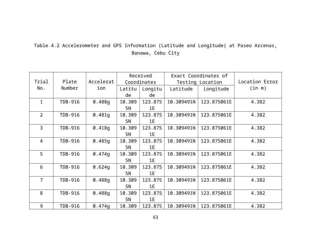
Table 4.23 Error of Location Data Acquired at Yati, Liloan
Trial No. Location Error (in m)
1 3.683 3.684 3.685 3.686 3.687 3.688 3.689 3.6810 3.68
Average Location Error (in m) 3.68
68

Table 4.24 Time Information Acquired at Yati, Liloan
Trial No. Received Time Info
Time Logged on Website
Data Time Delay
Time of SMS Received SMS Time Delay
1 2:49:44 AM 2:49:54 AM 0:00:10 2:50:00 AM 0:00:162 3:00:28 AM 3:00:30 AM 0:00:02 3:00:33 AM 0:00:053 3:02:40 AM 3:02:58 AM 0:00:18 3:03:30 AM 0:00:504 3:04:15 AM 3:04:45 AM 0:00:30 3:05:00 AM 0:00:455 3:07:00 AM 3:07:22 AM 0:00:22 3:08:02 AM 0:01:026 3:08:40 AM 3:09:11 AM 0:00:31 3:10:00 AM 0:01:207 3:12:32 AM 3:13:01 AM 0:00:29 3:13:25 AM 0:00:538 3:15:14 AM 3:15:30 AM 0:00:16 3:15:56 AM 0:00:429 3:18:02 AM 3:18:21 AM 0:00:19 3:18:40 AM 0:00:3810 3:20:12 AM 3:20:43 AM 0:00:31 3:21:17 AM 0:01:05
69

Table 4.25 Time Delay of Information Sending through GPRS at Yati, Liloan
Table 4.26 Time Delay of Information Sending through SMS at Yati, Liloan
Trial No. Data Time Delay
1 0:00:102 0:00:023 0:00:184 0:00:305 0:00:226 0:00:317 0:00:298 0:00:169 0:00:1910 0:00:31
Average Data Time Delay 0:00:21
Trial No. SMS Time Delay
1 0:00:162 0:00:053 0:00:504 0:00:455 0:01:026 0:01:207 0:00:538 0:00:429 0:00:3810 0:01:05
Average SMS Time Delay 0:00:46
70

Tables 4.27, 4.28, 4.29, 4.30 and 4.31 show the crash test information displayed on the website and received by the mobile phone at Busay, Lahug, Cebu City. On 10 out of the 10 trials (100%), the device was able to send the GPRS data successfully. On 10 out of the 10 trials (100%), the device was able to send the SMS text message successfully. Out of the 10 data successfully sent, none (0%) included erroneous information. Out of the 10 text messages successfully sent, none (0%) included erroneous information.
Table 4.27 shows the acceleration values which varied from 0.47g to 0.89g. In six trials, the location error, which is the distance between the received coordinates and the exact coordinates of testing, is 2.846 meters. In the remaining four trials, the location error is 13.84 meters.
Table 4.28 shows the average location error which is equal to 7.2436 meters.
Table 4.29 shows the timestamp data in every trial. The data time delay ranges from 0:00:04 to 0:00:37. The SMS time delay ranges from 0:00:08 to 0:00:51.
Table 4.30 shows the average data time delay which is equal to 0:00:12.
Table 4.31 shows the SMS time delay which is equal to 0:00:24.
71

Table 4.27 Accelerometer and GPS iNFORMATION (Latitude and Longitude) at Busay, Top’s Entrance Lahug
Trial No.Plate
Number AccelerationReceived Coordinates Exact Coordinates of Testing
Location Location Error (in m)Latitude Longitude Latitude Longitude
1 TDB-916 0.47g 10.3792N 123.8736E 10.379201N 123.873626E 2.8462 TDB-916 0.474g 10.3792N 123.8736E 10.379201N 123.873626E 2.8463 TDB-916 0.473g 10.3792N 123.8736E 10.379201N 123.873626E 2.8464 TDB-916 0.476g 10.3792N 123.8736E 10.379201N 123.873626E 2.8465 TDB-916 0.471g 10.3792N 123.8736E 10.379201N 123.873626E 2.8466 TDB-916 0.473g 10.3792N 123.8736E 10.379201N 123.873626E 2.8467 TDB-916 0.489g 10.3791N 121.8737E 10.379201N 123.873626E 13.848 TDB-916 0.489g 10.3791N 121.8737E 10.379201N 123.873626E 13.849 TDB-916 0.48g 10.3791N 123.8737E 10.379201N 123.873626E 13.8410 TDB-916 0.491g 10.3791N 123.8737E 10.379201N 123.873626E 13.84
72

Table 4.28 Error of Location Information Acquired at Busay, Top’s Entrance Lahug.
Trial No. Location Error (in m)
1 2.8462 2.8463 2.8464 2.8465 2.8466 2.8467 13.848 13.849 13.8410 13.84
Average Location Error (in m) 7.2436
73

Table 4.29 Time Information Acquired at Busay, Top’s Entrance Lahug
Trial No. Received Time Info
Time Logged on Website
Data Time Delay
Time of SMS Received SMS Time Delay
1 6:28:16 PM 6:28:21 PM 0:00:05 6:28:49 PM 0:00:332 6:30:39 PM 6:30:43 PM 0:00:04 6:30:47 PM 0:00:083 6:31:40 PM 6:31:45 PM 0:00:05 6:31:59 PM 0:00:194 6:32:29 PM 6:32:34 PM 0:00:05 6:32:54 PM 0:00:255 6:33:18 PM 6:33:24 PM 0:00:06 6:33:30 PM 0:00:126 6:38:41 PM 6:39:02 PM 0:00:21 6:39:10 PM 0:00:297 6:46:00 PM 6:46:37 PM 0:00:37 6:46:51 PM 0:00:518 6:48:00 PM 6:48:25 PM 0:00:25 6:48:41 PM 0:00:419 7:02:19 PM 7:02:23 PM 0:00:04 7:02:27 PM 0:00:0810 7:06:10 PM 7:06:16 PM 0:00:06 7:06:21 PM 0:00:11
74

Table 4.30 Time Delay of Information Sending through GPRS at Busay, Top’s Entrance Lahug
Trial No. Data Time Delay
1 0:00:052 0:00:043 0:00:054 0:00:055 0:00:066 0:00:217 0:00:378 0:00:259 0:00:0410 0:00:06
Average Data Time Delay
0:00:12
Table 4.31 Time Delay of Information Sending through GPRS at Busay, Top’s Entrance Lahug
Trial No. SMS Time Delay
1 0:00:332 0:00:083 0:00:194 0:00:255 0:00:126 0:00:297 0:00:518 0:00:419 0:00:0810 0:00:11
Average SMS Time Delay 0:00:24
75

Tables 4.32, 4.33, 4.34, 4.35 and 4.36 show the crash test information displayed on the website and received by the mobile phone at Nice Day Carwash - Escario, Cebu City. On 10 out of the 10 trials (100%), the device was able to send the GPRS data successfully. On 10 out of the 10 trials (100%), the device was able to send the SMS text message successfully. Out of the 10 data successfully sent, none (0%) included erroneous information. Out of the 10 text messages successfully sent, none (0%) included erroneous information.
Table 4.32 shows the acceleration values which varied from 0.442g to 0.478g. Trial No. 10 returned error in coordinates. In each of the other nine trials, the location error, which is the distance between the received coordinates and the exact coordinates of testing, is 2.083 meters.
Table 4.33 shows the average location error which is equal to 2.083 meters.
Table 4.34 shows the timestamp data in every trial. The data from Trial No. 10 was logged onto the website and received via SMS was erroneous. The data time delay ranges from 0:00:03 to 0:00:42. The SMS time delay ranges from 0:00:06 to 0:00:47.
Table 4.35 shows the average data time delay which is equal to 0:00:18. The data used in computing for the average only include nine trials since erroneous data was acquired from Trial No. 10.
Table 4.36 shows the SMS time delay which is equal to 0:00:32. The data used in computing for the average only include nine trials since erroneous data was acquired from Trial No. 10.
76
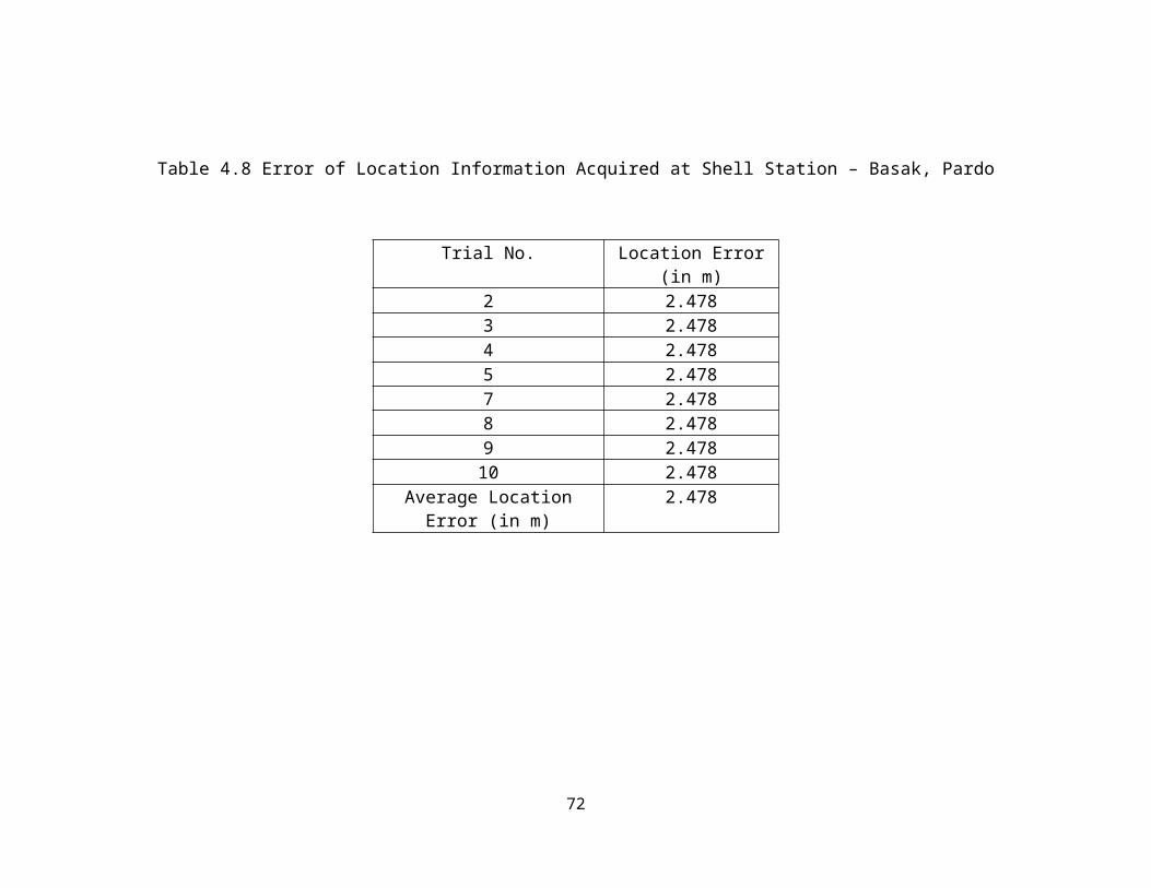
Table 4.32 Accelerometer and GPS Information (Latitude and Longitude) at Nice Day Carwash - Escario
Trial No.Plate
Number AccelerationReceived Coordinates Exact Coordinates of Testing
Location Location Error (in m)Latitude Longitude Latitude Longitude
1 TDB-916 0.466g 10.3181N 123.894E 10.318083N 123.894122E 2.0832 TDB-916 0.461g 10.3181N 123.894E 10.318083N 123.894122E 2.0833 TDB-916 0.475g 10.3181N 123.894E 10.318083N 123.894122E 2.0834 TDB-916 0.461g 10.3181N 123.894E 10.318083N 123.894122E 2.0835 TDB-916 0.442g 10.3181N 123.894E 10.318083N 123.894122E 2.0836 TDB-916 0.471g 10.3181N 123.894E 10.318083N 123.894122E 2.0837 TDB-916 0.461g 10.3181N 123.894E 10.318083N 123.894122E 2.0838 TDB-916 0.478g 10.3181N 123.894E 10.318083N 123.894122E 2.0839 TDB-916 0.477g 10.3181N 123.894E 10.318083N 123.894122E 2.08310 TDB-916 0.474g 89.7333N 19.0014E 10.318083N 123.894122E ERROR
77

Table 4.33 Location Error of Location Data Acquired at Nice Day Carwash - Escario
Trial No. Location Error (in m)
1 2.0832 2.0833 2.0834 2.0835 2.0836 2.0837 2.0838 2.0839 2.083
Average Location Error (in m) 2.083
78

Table 4.34 Time Information Acquired at Nice Day Carwash - Escario
Trial No. Received Time Info
Time Logged on Website
Data Time Delay Time of SMS Received
SMS Time Delay
1 7:24:43 PM 7:24:58 PM 0:00:15 7:25:30 PM 0:00:472 7:26:11 PM 7:26:35 PM 0:00:24 7:26:40 PM 0:00:293 7:28:12 PM 7:28:20 PM 0:00:08 7:28:39 PM 0:00:274 7:35:05 PM 7:35:47 PM 0:00:42 7:35:36 PM 0:00:315 7:36:11 PM 7:36:52 PM 0:00:41 7:36:54 PM 0:00:436 7:37:24 PM 7:37:39 PM 0:00:15 7:38:06 PM 0:00:427 7:39:12 PM 7:39:20 PM 0:00:08 7:39:56 PM 0:00:448 7:40:53 PM 7:40:59 PM 0:00:06 7:41:09 PM 0:00:169 7:42:25 PM 7:42:28 PM 0:00:03 7:42:31 PM 0:00:0610 8:11:47 AM 7:46:22 PM ERROR 7:48:31 PM ERROR
79

Table 4.35 Time Delay of Information Sending through GPRS at Nice Day Carwash – Escario
Trial No. Data Time Delay
1 0:00:152 0:00:243 0:00:084 0:00:425 0:00:416 0:00:157 0:00:088 0:00:069 0:00:03
Average Data Time Delay 0:00:18
Table 4.36 Time Delay of Information Sending through GPRS Acquired at Nice Day Carwash – Escario
Trial No. SMS Time Delay
1 0:00:472 0:00:293 0:00:274 0:00:315 0:00:436 0:00:427 0:00:448 0:00:169 0:00:06
Average SMS Time Delay 0:00:32
80

Table 4.37 Summary of the Performance of the System
Place GPRS Sent SMS Sent Erroneous GPRS Data
Erroneous SMS Data
Location Error Data Time Delay
SMS Time Delay
Banawa, Cebu City
90% 100% 0% 0% 4.382m 19sec 26sec
Basak, Cebu City
90% 100% 10% 20% 2.478m 54sec 59sec
North Reclamation
100% 100% 0% 0% 3.56m 19sec 1.07sec
Lapu-lapu City 100% 100% 10% 10% 69.722m 18sec 36sec
Yati, Liloan 100% 100% 10% 10% 3.68m 21sec 46sec
Busay, Lahug 100% 100% 0% 0% 7.2436m 12sec 24sec
Escario, Cebu City
100% 100% 0% 0% 2.083m 18sec 32sec
Table 4.37 shows the summary of the performance of the system in terms of failure in sending through GPRS and/or SMS, time elapsed between sending and receiving, errors in time and position information received, and errors in sending. Failures in GPRS sending occurred due to the limited connection of the device to the service provider. In Banawa and Basak, Cebu City, the mobile phone signal ranges from 3-5 out of 5 bars. The inconsistency of the strength of connection to the service from time to time opens the possibility of failure in sending via GPRS. However, the sending of data via SMS works properly in all of the trials made. Occurrence of erroneous GPRS and SMS data were also listed. There were few instances that the data gathered by the GPS module such as the coordinates of the location and the time stamp data are different from the ideal values. This may be caused by the physical obstructions surrounding the area like large infrastructures and the bad weather conditions during testing. The data and SMS time delays in the successful transmissions are considerably small.
81
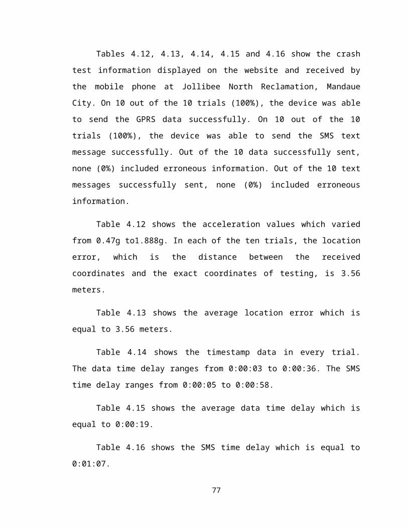
Chapter 5
Summary, Conclusions and Recommendations
5.1 Summary
In this study, a system was designed which detects collision and has automatic
advisory and data management system for vehicular collisions. The accelerometer used in
the device was calibrated and tested to ensure the reliability of its sensing function. A
code was also uploaded to the microcontroller to extract location and time stamp
information from the GPS module and transmit this information using the GSM/GPRS
module. The system’s performance is analyzed in terms of failure in sending through
GPRS and/or SMS, time elapsed between sending and receiving, errors in time and
position information received, and errors in sending. The testing results showed that the
device is capable of executing processes to detect collision and sending the acquired
collision information to the database via GPRS and mobile phones via SMS at an
efficient time. However, certain conditions affect the device which caused it to return
erroneous data – conditions or factors which cannot be controlled and out of the scope of
the study. The limited access the service provider gives in specific areas caused the delay
in sending of the collision information. The physical environment and weather and
atmospheric conditions at a particular time also affected the accuracy of the GPS data.
5.2 Conclusions
A small-scale in-vehicle sensor system that detects collision was designed using
ADXL345 3-Axis Digital Accelerometer as the crash sensor and the ATmega644
GizDuino+ as the microcontroller. Although the system was not tested in an actual crash;
it detects acceleration values beyond the set threshold of the accelerometer and classifies
82

it as a “collision”. Using the GPS and GSM/GPRS modules mounted on the
microcontroller, the device acquires location of the collision and time stamp data and
sends it to the defined mobile phones as a text message and logs it into the database. The
delay, failure and success of transmission of text message varies accordingly to the GSM
signal obtained from a certain location while the delay, failure and success of
transmission of data to the database varies accordingly to the EDGE signal obtained from
that location. The erroneous data obtained from the GPS shield were due to factors which
are out of scope of the study – obstructions or infrastructures surrounding the prototype,
terrain of the location and the location’s satellite reception. The data logged and stored in
the database is then displayed on the webpage with the domain, sirena1234.vacau.com
with the use of PHP coded pages. The objectives stated in this thesis project were met.
5.3 Recommendations
After a thorough analysis of the data, the following recommendations have been
made:
The antenna of the GSM/GPRS module should be modified and improved to
acquire wider coverage and higher signal strength.
The GPS module should be replaced with one which produces a more accurate
and consistent coordinates to gather more reliable location and time information.
The power supply used for the client module should be specified to operate on a
daily basis and should be able to provide the needed power for a longer span of
time to the Client Module to prevent interruption in the system operation.
A back-up power supply for the Client Module in order to ensure the continuous
operation of the system.
Different network providers that provide service within the Philippines should be
tested and acquired data from the testing should be compared, in order to improve
the efficiency and delay of transmission of data and text message.
83

A new method of testing – one that is closer to actual crash testing should be
employed in triggering the extraction of data from accelerometer, and GPS
Shield.
A high-range accelerometer, specifically designed to detect impacts or crash
should be used as the sensor in the Client Module.
Crash sensors other than accelerometers such as pressure and vibration sensors
should also be incorporated to the system, for a better and sensitive crash sensing.
A casing specifically designed for the Client Module should be used, in order to
protect the modules and to ensure the fixation of the wired connections between
the microcontroller unit and its compatible shields.
A host with a server that operates on the GMT+8 time zone should be utilized, in
order to lessen the need of converting timestamps into its designated time zones
for the convenience of displaying it to the website users or viewers.
84

Bibliography
[1] DOH National Electronic Injury Surveillance System (NEISS) Factsheet Volume 3, Issue 3, December 2011.
[2] DOH National Electronic Injury Surveillance System (NEISS) Factsheet Volume 3, Issue 4, February 2012.
[3] DOH National Electronic Injury Surveillance System (NEISS) Factsheet Volume 4, Issue 1, May 2012.
[4] Feero S., Hedges JR., Simmons E., Irwin L., “Does out-of-hospital EMS time affect trauma survival?,” in The American Journal of Emergency Medicine: 133-135, 1995.
[5] Patrol 117 “failure”: DILG blames lack of budget for equipment maintenance. The Freeman, November 2009.
[6] ASEAN Region Road Safety Strategy and Action Plan, May 2006.
[7] R. Filjar, K. Vidovic, P. Britvic, M. Rimac, "eCall: Automatic Notification of a Road Traffic Accident," in MIPRO: 600-605, 2011.
[8] C. Pinart, J. C. Calvo, L. Nicholson, J. Villaverde, "Ecall-compliant early crash notification service for portable and nomadic devices," in Vehicular Technology Conference: 1-5, 2009.
[9] Goh, Ng, Jusoff, Chen, Tan, "Architecture of a GPS-Based Road Management System," in World Applied Sciences Journal: 26-31, 2011.
[10] White, Thompson, Turner, Dougherty, Schmidt, "WreckWatch: Automatic Traffic Accident Detection and Notification with Smartphones," in Mobile Networks and Applications - Volume 16 Issue 3: 285-303, 2011.
[11] A. Khan, R. Mishra, "GPS-GSM Based Tracking System," in International Journal of Engineering Trends and Technology - Vol. 31 Issue 2: 161-164, 2012.
[12] Analog Devices, “ADXL345: A 3-Axis, ±2 g/±4 g/±8 g/±16 g Digital Accelerometer,” 2011.
[13] ATMEL, “ATmega644/V: 8-bit Atmel Microcontroller with 64K Bytes In-System Programmable Flash,” 2012.
[14] SIMCOM, “SIM900D GSM/GPRS Module,” 2010.
[15] Analog Devices, “Using Accelerometer for Inclination Sensing,” 2010.
85

86