final industry review march 2015 - higher logic · asme y14.34 associated lists, engineering...
TRANSCRIPT
IPC-D-620
DESIGN AND CRITICAL PROCESS REQUIREMENTS
FOR CABLE AND WIRING HARNESSES
FINAL INDUSTRY REVIEW MARCH 2015

DOCUMENT for FINAL INDUSTRY REVIEW
APRIL 2015
2
Figure 1 - Hierarchy of IPC Design Specifications (IPC-D-620 Series) This standard is intended to provide information on the design requirements for cable and wiring harness design, to the extent that they can be applied to the broad spectrum of cable and wiring harness design. It is therefore crucial that decisions concerning the choice of product classification, wiring technology, connectorization requirements, and performance and reliability requirements be made as early as possible. IPC-D-620 is supplemented by Appendices A-C and a handbook (IPC-HDBK-620), which provide the engineering rationale and technical guidance on cable and wiring harness design. The User needs, as a minimum, the Design Requirements document (IPC-D-620), and the engineering description of the final product. As wiring and connector technology changes, specific requirements will be updated or new requirements added to the document set. The IPC invites input on the effectiveness of the documentation and encourages User response through completion of ‘‘Suggestions for Improvement’’ forms located at the end of each document.
HIERARCHY OF IPC DESIGN SPECIFICATIONS
(IPC-D-620 SERIES)
IPC-D-620
DESIGN
IPC-HDBK-620
HANDBOOK Appendix A
Military / Space Applications Requirements
Appendix B Electrical Wire And Cable Acceptance Tests
Appendix C Bend Radius

DOCUMENT for FINAL INDUSTRY REVIEW
APRIL 2015
3
TABLE OF CONTENTS - TO BE DEVELOPED BY IPC AT TYPESETTING 1 GENERAL 1.1 Scope This document provides design and critical process requirements and technical insight that have been removed from the acceptance standards for cable and wire harness assemblies. Reference materials listed in this text are among those considered as required reading. The User is encouraged to obtain all relevant referenced materials as this document cannot (nor can any single document) cover every material, process, environment, performance, or safety aspect that affect a given design. 1.2 Purpose “Design Requirements for Cable and Wiring Harnesses” is the cable and wiring harness and systems-level design requirements companion to IPC/WHMA-A-620, “Requirements and Acceptance for Cable and Wire Harness Assemblies”, and its associated space addendum. The intent of this document is to set forth the general design requirements for electrical wiring harnesses and cable assemblies. This document is intended for use by the design engineer, manufacturing engineer, quality engineer, or other individual responsible for the tailoring of specific requirements of this document to the applicable performance class. For purposes of this document:
- The Designer is the design agent for the User.
- The User is the entity that receives a service or product, and is considered the Design Authority
- The Supplier is considered the entity that provides a service or product to the User
1.3 Performance/Product Classification This document recognizes that electrical wiring harnesses and cable assemblies are subject to performance / product classifications by intended end-item use. Three general end-product classes have been established to reflect differences in producibility, complexity, functional performance requirements, and verification (inspection/test) frequency. It SHOULD be recognized that there may be requirement overlaps between classes. The User is responsible for defining the product class. The contract shall [A1A2A3] specify the performance class required, whether compliance to any of the A through G Appendices is required, and indicate any exceptions to specific parameters where appropriate. Class 1 - General Electronic Products Includes consumer products, as well as general military hardware suitable for applications where cosmetic imperfections are not important and the major requirement is function of the completed assembly. Class 2 - Dedicated Service Electronic Products Includes products where continued performance and extended life is required, and for which uninterrupted service is desired but not critical. Typically, the end-use environment would not cause failures. Class 3 - High Performance Electronic Products Includes products where continued high performance or performance-on-demand is critical, equipment downtime cannot be tolerated, end-use environment may be uncommonly harsh, and the equipment must function when required, such as life support or other critical systems. Space Space classification deviations to IPC-D-620 are defined and listed in Appendix A.

DOCUMENT for FINAL INDUSTRY REVIEW
APRIL 2015
4
1.4 Definition of Requirements The imperative form of action verbs are used throughout this document to identify design requirements that may require compliance, depending upon the Performance Classification of the hardware. To assist the User, these action verbs are in bold text.
a. SHALL / SHALL NOT. The words shall or shall not are used whenever a requirement is intended to express a provision that is mandatory. Deviation from a shall or shall not requirement for a particular Performance Class may be considered if sufficient technical rationale / objective evidence (OE) is supplied to the User to justify the exception.
b. SHOULD. The word should is used whenever a requirement is intended to express a provision that is non-mandatory, and which reflects general industry practice and / or procedure.
1.4.1 Requirement Format (A/N) The requirements in this document are formatted to allow verification and validation (V&V). To assist the User, each requirement is identified by its Performance Classification (x1x2x3) and applicability, where “x” represents:
N = Not Applicable
A = Applicable Examples:
[N1N2N3] = Not Applicable for any Class
[N1N2A3] = Not Applicable for Class 1 or Class 2; Applicable for Class 3
[N1A2A3] = Not Applicable for Class 1; Applicable for Class 2 and Class 3
[A1A2A3] = Applicable for all Classes
1.4.2 Line Drawings and Illustrations Line drawings and illustrations are depicted herein to assist in the interpretation of the written requirements of this standard. The written requirement always takes precedence over the drawings and illustrations. 1.5 Measurement Units and Applications All dimensions and tolerances, as well as other forms of measurement in this standard are expressed in SI (System International) units, with Imperial English equivalent dimensions provided in [brackets].
a. Linear dimensions and tolerances use centimeters (cm) [inches (in)] as the main form of dimensional expression; millimeters (mm) [inches (in)] or micrometers (µm) [microinches (µin)] are used when the required precision makes the use of centimeters (cm) too cumbersome.
b. Temperature values are expressed in degrees Celsius (°C) [Fahrenheit (°F)].
c. Mass is expressed in grams (g) [ounces (oz)].
d. Wire, wire harness, and cable diameters are expressed in the non-dimensional unit (d), where a numerical dimension, such as 2d, is solely dependent on a physical attribute of the hardware (e.g.: wire gauge, harness diameter, etc.).
For the purposes of determining conformance to this specification, all specified limits in this standard are absolute limits as defined in ASTM E29.
1.6 Definition of Terms For purposes of this document, the acronyms, abbreviations, and terms used, but in addition to those listed in IPC-T-50, “Terms and Definitions for Interconnecting and Packaging Electronic Circuits” are listed in Section 10 “Definitions and Acronyms”. 1.7 Engineering Documentation The design engineer is responsible for ensuring that all applicable design details are clearly and completely depicted on the engineering documentation (drawings), including manufacturing, assembly,

DOCUMENT for FINAL INDUSTRY REVIEW
APRIL 2015
5
and test methods and Standards. Drawings shall [A1A2A3] document, including the appropriate Product Class, that cable and harness assemblies shall [A1A2A3] be fabricated, inspected, and tested in accordance with IPC/WHMA-A-620 and/or IPC/WHMA-A-620X-S, for the particular Product Class, unless otherwise specified by the User 1.8 Order of Precedence The contract always takes precedence over this document, referenced standards and drawings. 1.8.1 Conflict a. In the event of conflict between the requirements of this document and the approved assembly
drawing(s) / documentation, the User approved assembly drawing(s) / documentation shall [A1A2A3] govern.
b. In the event of a conflict between the text of this document and the applicable documents cited herein, the text of this document shall [A1A2A3] take precedence.
c. In the event of conflict between the requirements of this document and an assembly drawing(s)/ documentation that has not been User approved, this document shall [A1A2A3] govern.
d. If no criteria is specified, required, or cited, criteria shall [A1A2A3] be established and agreed upon between the Manufacturer and User.
1.8.2 Clause References When a clause in this document is referenced, its subordinate clauses shall [A1A2A3] also apply. 1.9 Appendices A-C For the purpose of this document, Appendices A-C are considered separate and optional documents to IPC-D-620, which additional engineering rationale and technical guidance on cable and wiring harness design.
a. Appendices A-C shall not [A1A2A3] be binding, unless separately and specifically invoked by the applicable contract, approved drawing(s), or purchase order.
b. When invoked, the applicable requirements of the appendices shall [A1A2A3] be imposed on all applicable subcontracts, assembly drawing(s), documentation and purchase orders.
c. When not invoked, the applicability of the Appendices, individual requirements of the Appendices, and/or flowdown of said appendices and/or individual requirements shall [A1A2A3] be AABUS.
1.10 Approval of Departures from Standards and Requirements This document is intended for use in specifications or contracts to incorporate requirements which are common to most cable and wiring harness designs, and establishes the minimum design requirements for most applications. Special requirements may exist which are not covered by, do not comply with, or which are in conflict with program-specific documents, and / or program-specified design requirements. The requirements herein may be tailored by the DESIGNER; however, such tailoring shall [A1A2A3] be approved by the User prior to use. Engineering documentation shall [A1A2A3] contain the details for such instances, and take precedence over appropriate sections of this document and the applicable requirements document(s).
DOCUMENT for FINAL INDUSTRY REVIEW
APRIL 2015
6
2 APPLICABLE DOCUMENTS The following documents form a part of this document to the extent specified herein. Unless otherwise specified, the issue / revision in effect on the date of bids, or request for proposal, shall [A1A2A3] apply. 2.1 Aerospace AIR1329 Electrical Connectors and Wiring, Compatibility of AIR4487 Investigation of Silver Plated Conductor Corrosion (Red Plague) AS4373 Test Methods for Insulated Electric Wire AS22759 Wire, Electric, Fluoropolymer-Insulated Copper or Copper Alloy (Slash Sheet: /11, /89B, /90B, 91B, /92B) AS9100 Quality Management Systems - Requirements for Aviation, Space and Defense Organizations 2.2 Commercial ANSI/EIA-359-A Standard Colors for Color Identification and Coding ANSI/NEMA WC 27500 Standard for Aerospace and Industrial Electrical Cable ASME Y14.100 Engineering Drawing Practices ASME Y14.24 Types and Applications of Engineering Drawings ASME Y14.34 Associated Lists, Engineering Drawing and Related Documentation Practices ASME Y14.35 Revision of Engineering Drawings and Associated Lists ASME Y14.44 Revision Designations for Electrical and Electronics Parts and Equipment ASTM E595 Standard Test Method for Total Mass Loss and Collected Volatile Condensable Materials from Outgassing in a Vacuum Environment GEIA-STD-0005-s Standard for Mitigating the Effects of Tin Whiskers in Aerospace and High Performance Electronic Systems IEEE Std 260.1 Standard Letter Symbols for Units of Measurement (SI Units, Customary Inch-Pound Units, and Certain Other Units) IPC-1071 Best Industry Practices for Intellectual Property Protection in Printed Board Manufacturing IPC-TM-650 IPC Test Methods Manual WP-013 Red Plague Control Plan WP-014 White Plague Control Plan

DOCUMENT for FINAL INDUSTRY REVIEW
APRIL 2015
7
WP-015 Lead Free Control Plan (LFCP) WP-016 Foreign Object Debris (FOD) Control Plan IPC/WHMA-A-620 Requirements and Acceptance for Cable and Wire Harness Assemblies IPC/WHMA-A-620X-S Space Applications Electronic Hardware Addendum to IPC/WHMA-A- 620 J-STD-001 Requirements for Soldered Electrical and Electronic Assemblies J-STD-001 Space Hardware Addendum Space Applications Electronics Hardware Addendum to IPC J-STD-001 Requirements for Soldered Electrical and Electronic Assemblies ARP6167 Etching of Fluoropolymer Insulations
2.3 Federal NASA-STD-6001 Flammability, Odor, Offgassing and Compatibility Requirements and Test Procedures for Materials in Environment That Support Combustion 2.4 Military Handbooks
None 2.5 Military Specifications MIL-C-L-17 Cables, Radio Frequency, Flexible and Semi-rigid, General Specification for MIL-STD-704 Aircraft Electric Power Characteristics 2.6 Reference
The documents listed below provide technical guidance. Unless otherwise specified, the requirements and recommendations in these documents are not binding and are not to be construed as implied requirements.
A-A-52080 Tape, Lacing and Tying, Nylon A-A-52081 Tape, Lacing and Tying, Polyester A-A-52082 Tape, Lacing and Tying, TFE-Fluorocarbon A-A-52083 Tape, Lacing and Tying, Glass A-A-52084 Tape, Lacing and Tying, Aramid A-A-59569 Commercial Item Description, Braid, Wire (Copper, Tin-Coated, Silver- Coated, or Nickel Coated, Tubular or Flat AIR4789 Aerospace Information Report on Evaluating Corrosion Testing of Electrical Connectors and Accessories for the Purpose of Qualification AIR5468 Ultraviolet (UV) Lasers for Aerospace Wire Marking

DOCUMENT for FINAL INDUSTRY REVIEW
APRIL 2015
8
AIR5558 Ultraviolet (UV) Laser Marking Performance of Aerospace Wire Constructions AIR5575 Hot Stamp Wire Marking Concerns for Aerospace Vehicle Applications AIR5717 Mitigating Wire Insulation Damage during Processing and Handling AMS 2491 Surface Treatment of Polytetrafluoroethylene, Preparation for Bonding AS4461 Assembly and Soldering Criteria for High Quality/High Reliability Soldered Wire and Cable Termination in Aerospace Vehicles AS5382 Aerospace Cable, Fiber Optic AS5649 Wire and Cable Marking Process, UV Laser AS7928 Terminals, Lug: Splices, Conductor: Crimp Style, Copper, General Specification For AS21608 Ferrule, Shield Terminating, Crimp Style AS23190 Wiring, Positioning and Support Accessories AS81044 Wire, Electric, Crosslinked Polyalkene, Crosslinked Alkane-Imide Polymer, or Polyarylene Insulated, Copper or Copper Alloy AS83519 Shield Termination, Solder Style, Insulated, Heat-Shrinkable, Environment Resistant, General Specification for (Slash Sheet: /1, /2) ASTM B174 Standard Specification for Bunch-Stranded Copper Conductors for Electrical Conductors ASTM B8 Standard Specification for Concentric-Lay-Stranded Copper Conductors, Hard, Medium-Hard, or Soft ASTM B172 Standard Specification for Rope-Lay-Stranded Copper Conductors Having Bunch-Stranded Members, for Electrical Conductors ASTM B173 Standard Specification for Rope-Lay-Stranded Copper Conductors Having Concentric-Stranded Members, for Electrical Conductors ASTM B263 Standard Test Method for Determination of Cross-Sectional Area of Stranded Conductors ASTM B738 Standard Specification for Fine-Wire Bunch-Stranded and Rope-Lay Bunch-Stranded Copper Conductors for Use as Electrical Conductors DOD-HDBK-83575 General Handbook for Space Vehicle Wiring Harness Design and Testing IACS (UR) E11 E-11 Unified Requirements for Systems with Voltages Above 1kV up to 15kV, International Association of Classification Societies, Concerning Electrical Installations IEC 60617 Graphical Symbols for Diagrams, Database Snapshot

DOCUMENT for FINAL INDUSTRY REVIEW
APRIL 2015
9
IEEE Std 315 Graphic Symbols for Electrical and Electronics Diagrams (Including Reference Designation Letters) IPC-2611 Generic Requirements for Electronic Product Documentation IPC-OI-645 Standards for Visual Optical Inspection Aids J-STD-002 Solderability Tests for Component Leads, Terminations, Lugs, Terminals and Wires J-STD-004 Requirements for Soldering Fluxes J-STD-006 Requirements for Electronic Grade Solder Alloys and Fluxed and Non- Fluxed Solid Solders for Electronic Soldering Applications MIL-A-46146 Adhesives-Sealants, Silicone, RTV, Noncorrosive (For Use with Sensitive Metals and Equipment) MIL-C-27500 Cable, Electrical Shielded and Unshielded, Aerospace MIL-C-39012 Connector, Coaxial, Radio-Frequency, General Specification for MIL-DTL-5846 Chromel and Alumel Thermocouple Electrical Wire, Detail Specification for MIL-DTL-24308 Connectors, , Electrical, Rectangular, Non-environmental, Miniature, Polarized Shell, Rack and Panel, General Specification for MIL-DTL-38999 Connectors, Electrical, Circular, Miniature, High Density, Quick Disconnect, (Bayonet, Threaded, and Breech Coupling), Environmental Resistant, Removable Crimp and Hermetic Solder Contacts, General Specification for MIL-DTL-81381 Wire, Electric, Polyimide-Insulated, Copper or Copper Alloy, General Specification for MIL-DTL-83723 Connectors, Electrical, (Circular, Environment Resisting), Receptacles and Plugs, General Specification for MIL-DTL-83733 Connectors, Electrical, Miniature, Rectangular Type Rack to Panel, Environment Resisting, 200°C Total Continuous Operating Temperature, General Specification for MIL-HDBL-216 R. F. Transmission Lines and Fittings; cancelled 8 Sept 2001; no replacement MIL-HDBK-853 Handbook for Wiring Data and System Schematic Diagrams Preparation of MIL-I-631 Insulation, Electrical, Synthetic-Resin Composition, Non-Rigid MIL-I-22129 Insulation Tubing, Electrical, Polytetrafluoroethylene (PTFE) Resin, Non- Rigid MIL-I-23053 Insulation Sleeving, Electrical, Heat Shrinkable, General Specification for MIL-PRF-39012 Connectors, Coaxial, Radio Frequency, General Specification for

DOCUMENT for FINAL INDUSTRY REVIEW
APRIL 2015
10
MIL-STD-202 Test Method Standard, Electronic and Electrical Component Parts (Method 107, Test Condition B) MIL-STD-1399-Sect. 680 High Voltage Electric Power, Alternating Current MIL-STD-1472 Human Engineering MIL-T-43435 Tape, Impregnated, Lacing, and Tying MIL-W-22759 Wire, Electric, Fluoropolymer-Insulated Copper or Copper Alloy MIL-W-83575 Military Specification Wiring Harness, Space Vehicle, Design and Testing, General Specifications for – This is superseded by DOD-W- W83575A (USAF) NA-GSFC-2003-03 NASA Goddard Advisory, Fluoropolymer Degradation Resulting in Corrosion of Packaged Pre-wired Connector Assemblies NASA PUBLICATION 1124 Outgassing Data for Selecting Spacecraft Materials (http://outgassing.nasa.gov) NASA-STD-6016 Standard Materials and Processes Requirements for Spacecraft NASM 33540 Safety Wiring, Safety Cabling, Cotter Pinning, General Practices for NFPA 70 National Electrical Codes QQ-B-575 Braid, Wire Copper, Tin-Coated Tubular
3 DESIGN PHILOSOPHY (Figure 3-1)
Figure 3-1 Wire, Cables, and Harnesses (Photo Courtesy of NASA)
Cables and wiring harnesses are equivalent to the human circulatory and nervous system. They deliver energy, transmit command and control instructions, and collect and distribute sensory data describing not only the environment external to the system, but the health and status of the system itself. Often the most overlooked, ignored, and “taken for granted” component in a design, high quality cables and wiring harnesses are essential to the performance and reliability of any electrical / electronic system. It is the Supplier's responsibility to ensure that the technical issues associated with the design and manufacture of cable assemblies and wiring harnesses are conveyed to the User, and that a dialogue is established, so that appropriate and timely decisions are made commensurate with realistic expectations and reality. After all, it doesn’t matter how elegant or innovative the design is if the cable assembly or wiring harness cannot be built, doesn’t fit, or won’t perform as required during use.
DOCUMENT for FINAL INDUSTRY REVIEW
APRIL 2015
11
3.1 General Design Requirements The design of electrical wiring harnesses and cable assemblies shall [A1A2A3] be based on the known worst-case operational requirements and expected use. These include, but are not limited to: assembly processes; shipping and storage; installation; test exposure; service environment (operational temperature limits, mechanical, thermal, and vibration stress; contamination; corrosives; EMC/EMI/RFI, ionizing / non-ionizing radiation, moisture or other fluid media exposure); post-use test and data recovery; and, life expectancy. The basic design considerations to assure reliable interconnecting cable and wire assemblies include, but are not limited to:
a. The physical and electrical properties of the wire and cable, including gauge/size; base metal; coatings; strand count and construction (e.g.: rope-lay strand, bunch-lay strand, concentric-lay-stranded, Litz / woven, etc.); weight; tensile strength; current and voltage derating; conductivity and signal propagation rates; etc.
b. The physical and electrical properties of the cable and harness assembly, including active and spare wire count; connectors; EMI / RFI / magnetic shielding; ionizing / non-ionizing radiation; construction (coaxial, discrete wire, hybrid, multi-conductor; optical fiber); redundancy; voltage drop; identification / marking; etc.
c. Material properties, including arc tracking resistance; chemical / material compatibility; flammability; odor, outgassing; low-pressure / vacuum stability; ultra-violet stability; resistance / reactance to corrosives, solvents, oxidizers, chemicals, etc.; resistance to heat / cold; resistance to abrasion damage and cold flow; etc.
d. Application issues, including acoustic, mechanical, thermal shock; acceleration (g-load); environment (condensing / corrosive / explosive atmosphere), electric field density (high voltage / lightning)
e. Non-metallic components - insulation jackets, potting materials, lacing tapes, braid sleeving, plastic straps, wrap sleeving, and plastic tubing
f. Special handling, storage, and processing requirements that may contribute to degradation of performance and/or reliability of hardware in service (i.e.: Red Plague / White Plague control)
g. Vulnerability to Foreign Object Debris (FOD) damage
h. Unique system-level testing requirements
i. Proprietary and export control compliance requirements
j. Environmental / Regulated materials (e.g.: RoHS, REACH, etc.)
k. Safety, maintainability, reliability, cost, etc.
3.2 System Requirements Specification (SyRS) The System Requirements Specification (SyRS), often referred to as the System Requirement Document (SRD), is a Design Authority-developed and structured collection of information that describes and defines the requirements, and verification of those requirements, for a combination of elements that must function together to produce the capabilities required to fulfill a mission need, including hardware, equipment, software, or any combination thereof. The SyRS shall [A1A2A3] contain the technical information needed by the Supplier to ensure the cable or wire harness design meets specification and delivers the required performance and reliability. Once the SyRS is placed on contract, the Supplier should further develop the specification and develop their own, more detailed requirements document baselined against their internal processes. System Requirements Specifications (SyRS) typically contain the following information:
a. Interface Control Document (ICD)

DOCUMENT for FINAL INDUSTRY REVIEW
APRIL 2015
12
b. Performance and Reliability Specifications
c. Environmental Specifications
d. Material Specifications
e. Packaging, Handling, Shipping, and Transportation (PHS&T) Requirements
f. Intellectual Property (IP) Control & Documentation Requirements
3.2.1 Document Interface Control (ICD)
The Interface Control Document (ICD) shall [A1A2A3] describe the interface or interfaces between sub-systems or to a system or sub-system, and contain the following information (as required) to ensure the cable or wire harness design meets specification and delivers the required performance and reliability: a. Circuit Types (power, signal, optical, etc.)
b. Schematic Diagrams
c. Mechanical Layouts and Dimensional Requirements
d. Connectors (type, location, contact style, etc.)
e. Connector Pin-outs
f. Power Allocation, Derating, Temperature Rating
g. EMI / EMC Requirements
h. Marking / Labeling Requirements.
i. Other I/F Requirements
3.2.2 Performance and Reliability The design shall [A1A2A3] assure that the overall performance and reliability requirements are met under the most severe extremes of acceptance testing, storage, transportation, and operational environments specified in the detail specification and/or contract. 3.2.2.1 Interchangeability Any two (2) or more wiring harnesses or cable assemblies bearing the same part number shall [A1A2A3] possess such functional and physical characteristics as to be equivalent in performance, durability, and connectivity; and, shall [A1A2A3] be capable of being changed, one for another, without alteration of the items themselves or of adjoining items. 3.2.2.2 Design for Maintainability (DFM) Cable and wiring harness assemblies shall [A1A2A3] be designed with features that contribute to the ease and rapidity of maintenance without removal of other equipment, interconnections, wire bundles, and / or fluid lines.
a. All wiring shall [A1A2A3] be accessible, repairable, and replaceable at the maintenance level specified by the User.
b. Cable and wiring harness length should provide enough additional wire length for reworking the entire connection at least one (1) time, at both ends of the wire.
c. Conductors connecting contacts within the same connector (i.e.: jumpers) shall [N1A2A3] be captivated or restrained (e.g.: cable clamp, wire tie, lacing, sealing gland, etc.).
d. Access – When cable and wiring harness assemblies are required to be disconnected and/or reconnected, the design shall [N1N2A3] incorporate sufficient flexibility, length, and protection to permit disconnection and reconnection without damage to wiring or connectors.
e. Ease of Connect / Disconnect - Electrical connections and cable installations should require no more than one (1) operation to disconnect and reconnect without damage to wiring or connectors.
3.2.2.3 Ergonomic Design

DOCUMENT for FINAL INDUSTRY REVIEW
APRIL 2015
13
Cables and wiring harnesses designed for use, or deployment, by humans shall [A1A2A3] be designed to work with the human body in the intended environment and application.
3.2.2.4 Service Life
Cables and wiring harnesses shall [A1A2A3] meet the design service life requirements specified in the detail specification and/or contract. 3.2.3 Workmanship Workmanship processes or criteria not covered by IPC/WHMA-A-620 shall [A1A2A3] be documented in engineering documentation. 3.2.4 Environmental Requirements Cables and wiring harnesses shall [A1A2A3] be capable of meeting the environmental design requirements specified in the detail specification and/or contract. 3.2.5 Packaging, Handling, Shipping, and Transportation (PHS&T) Cables and wiring harnesses shall [A1A2A3] be packaged, handled, shipped, and transported in accordance with the PHS&T requirements specified in the detail specification and/or contract. 3.2.6 Documentation Requirements The documentation package shall [A1A2A3] be in accordance with ASME Y14.100 (incl.: sub-set Y14.24, Y14.34, Y14.35, and Y14.44); the User-specified format; or, an equivalent format agreed upon by the Designer and User. See 8 – Documentation. 3.2.7 Intellectual Property (IP) Control Requirements The use, control, and disposition of tangible and intangible information related to the design and manufacture of the product, including data, drawings, engineering documentation, trade secrets, etc., shall [A1A2A3] be in accordance with IPC-1071; the User-specified control plan; or, an equivalent control plan agreed upon by the Designer and User.

DOCUMENT for FINAL INDUSTRY REVIEW
APRIL 2015
14
Figure 3-2 Cable and Harness Design Process
4 SELECTION OF PARTS, MATERIALS AND PROCESSES Unless otherwise specified in the contract, the parts, materials, and processes shall [A1A2A3] be selected and controlled in accordance with the approved Materials and Processes Plan / Requirements, and specified on the drawing. 4.1 Commonality An additional objective in the selection of parts, materials, and processes should be to maximize commonality and thereby minimize the variety of parts, related tools, and test equipment required in the fabrication, installation, and maintenance of cables and wiring harness assemblies.
a. Whenever a selected specification provides more than one (1) characteristic or tolerance for an item, the Supplier shall [A1A2A3] use items of broadest characteristics in the equipment and of the greatest allowable tolerances that will fulfill the performance and reliability requirements of the design.
b. A readily available item of equivalent form, fit, and function that, (a) meets the specified minimum quality requirements, and that (b) does not increase life cycle cost, may be used.
4.2 Flammability Insulation materials shall [A1A2A3] be non-combustible or self-extinguishing. Selection and use shall [A1A2A3] be traceable to acceptable flammability test reports. 4.3 Outgassing

DOCUMENT for FINAL INDUSTRY REVIEW
APRIL 2015
15
Collected Volatile Condensable Material (CVCM) outgassing of nonmetallic materials shall not [A1A2A3] exceed Total Mass Loss (TML) specified by contract. 4.4 Toxic Products And Formulations The use of toxic products and formulations used throughout manufacture, assembly, test, and checkout shall [A1A2A3] conform to all local, state, and federal (national) safety and environmental regulations. For United States facilities, all Occupational Safety and Health Administration (OSHA) and Environmental Protection Agency (EPA) regulations apply.
4.5 FOREIGN OBJECT DEBRIS (FOD) CONTROL PLAN A Foreign Object Debris (FOD) Prevention Program (a.k.a.: FOD Control Plan) shall be established for the design, development, manufacturing, assembly, repair, processing, testing, maintenance, operation, and check out of cable and wiring harness assemblies to prevent immediate and latent damage, and to ensure compliance to the specified cleanliness level. See WP-016, Foreign Object Debris (FOD) Control Plan, for technical guidance. 4.5 Prohibited / Restricted Usage Parts, Materials, Processes (PMP) Unless otherwise specified in the contract, the use of the following Parts, Materials, and Processes (PMP) shall [A1A2A3] be prohibited or restricted: 4.5.1 Acetic Acid Cure RTV Silicone Sealants, Adhesives, and Coatings Acetic acid cure RTV silicone sealants, adhesives, and coatings shall not [A1A2A3] be used in the assembly or manufacture of electrical wiring harnesses and cable assemblies or as environmental sealants for electrical enclosures (e.g.: conduit, fittings, boxes, etc.).
Rationale: Release of acetic acid during cure of Room Temperature Vulcanizing (RTV) silicones creates potential corrosion and contamination. 4.5.2 Beeswax Wax (ALL TYPES) a. Beeswax impregnated lacing tape shall not [N1N2A3] be used in critical application, Class 3, and/or
Space products, without prior User approval. b. Wax impregnated lacing tape shall not [A1A2A3] be exposed to cleaning solvents.
Rationale: (1) Organic materials, such as beeswax, may provide a nutrient source for fungal growth that may adversely affect unit performance or service life or constitute a health hazard to higher order life; or, serve as a fuel source (in the event of a fire). (2) No cleaning solvent / process may be used that can damage or degrade materials or reduce the performance or reliability of the hardware. 4.5.3 Beryllium (Be) Unalloyed beryllium (Be), and beryllium alloys containing greater than 4% (percent) beryllium by weight as an alloying constituent, shall not [A1A2A3] be used in critical application, Class 3, and/or Space products, unless suitably protected to prevent erosion, or formation of salts or oxides.
a. Environmental tests, under expected conditions, shall [A1A2A3] be conducted to verify that the coating used provides satisfactory protection for the beryllium surface.
b. Beryllium and alloys or oxides of beryllium shall not [A1A2A3] be ground, filed, drilled, sawed, or in any other way machined at any stage of manufacturing, assembly, testing, modification, or operation, without approved environmental compliance and Foreign Object Debris (FOD) programs and personal protective equipment (PPE) specifically designed for control of beryllium contamination / exposure.
c. Alloys containing 4% (percent) or less of beryllium by weight are specifically exempted from this requirement.
WARNING
The chemicals (i.e.: adhesives, cleaners, coatings, encapsulants, fluxes, solder alloys and solvents) used in electronic manufacturing, rework and repair processes can be HAZARDOUS, VOLATILE, REACTIVE, FLAMMABLE and/or FATAL if used incorrectly.

DOCUMENT for FINAL INDUSTRY REVIEW
APRIL 2015
16
Rationale: Beryllium is an extremely toxic material whose threshold limit is 0.002 mg/m3. Mists, dusts, or fumes containing beryllium or its compounds can cause a delayed type of pneumonitis that may manifest itself after an extended period of time. 4.5.4 Cadmium (Cd) Cadmium and cadmium plating on electrical connectors, cables, wiring harness assemblies, and mechanical hardware shall not [A1A2A3] be used where exposure to temperatures in excess of 75 °C [167 °F] and reduced atmospheric pressures could cause sublimation (vaporization) and deposition of cadmium on optical or electrically energized surfaces; in applications where the transfer migration of cadmium contamination is prohibited; or, in applications sensitive to the adverse effects of metallic whisker growth and contamination.
Rationale: (1) Cadmium has the ability to sublimate (vaporize), if exposed to temperatures in excess of 75 °C [167 °F], and reduced atmospheric pressure or vacuum. The resulting toxic, heavy-metal vapor can be inhaled by the User, or condense onto surfaces as a thin, electrically conductive layer, impacting the performance of electrical circuits and optical systems. (2) Cadmium plating on tool surfaces can be transferred to the surfaces of hardware and fasteners. (3) Cadmium is subject to the spontaneous growth of Cadmium whiskers. The propensity of Cadmium to grow whiskers appears to be lower than that of zinc (Zn) but higher than tin (Sn). Cadmium whiskers (like tin whiskers) grow spontaneously and are capable of causing electrical failures ranging from parametric deviations to sustained plasma arcing that can result in catastrophic short circuits. 4.5.5 Crimping Of Solder-Tinned and Solid Conductors Crimp termination of solder-tinned stranded wire and/or solid conductors, or the soldering of completed crimp terminations shall not [N1N2A3] be used in critical application, Class 3, and/or Space products. Designs requiring any of the following shall [A1A2A3] detail the process and acceptance criteria on the engineering documentation and prior approval from the User:
a. Crimping of solder-tinned stranded wire.
b. Crimping of solid wire
c. Soldering of completed crimp terminations.
Rationale: (1) Solder (a malleable alloy) acts as a variable thickness lubricant. The mechanical integrity of the crimp termination degrades as the solder coating deforms and flows under mechanical pressure and recrystallizes under temperature cycling. (2) Crimping of solid conductors is not allowed because the compression set process requires that the conductor have some “compressibility”. A solid wire is not compressible. Unless the crimp contact is perfectly sized for the conductor, the conductor cross-section is significantly reduced during compression set and micro-fractures develop, resulting in loss of current carrying capacity and reduced life. (3) Though often proposed as a means to ensure that a crimped termination is “bullet proof”, soldering a crimped termination produces a termination that is in violation of requirements for both a soldered termination and a crimped termination. Application of soldering temperatures to a completed crimp termination anneals the crimp, relaxing the compression set developed to produce the gas-tight cold-weld during the crimping process. Additionally, a crimp termination that has been soldered also violates the requirements for complete wetting, because the solder cannot flow into the compression zone and wet all the surfaces of the contact-conductor interface. 4.5.6 Cuprous Oxide Corrosion (Red Plague) (Figure 4-1)

DOCUMENT for FINAL INDUSTRY REVIEW
APRIL 2015
17
Figure 4-1 Red Plague (Cuprous Oxide Corrosion) (Photo Courtesy of NASA) When the use of silver-coated copper conductors (e.g.: wiring, shielding, terminations, etc.) is determined to be a performance and reliability concern, a Red Plague Control Plan (RPCP)” shall [A1A2A3] be invoked by contract. See IPC-TM-1116, Red Plague Control Plan (RPCP) for technical guidance and requirements.
Rationale: Red Plague (cuprous oxide corrosion) can develop in silver-coated soft or annealed copper conductors (component leads, single and multi-stranded wires and PCB conductors) when a galvanic cell forms between the copper base metal and the silver coating in the presence of moisture (H2O) and oxygen (O2) at an exposed copper-silver interface (i.e.: conductor end, pin-hole, scratch, nick, etc.).
4.5.7 Fluorine Attack (White Plague) (Figure 4-2)
Figure 4-2 White Plague (Fluorine Attack) (Photo Courtesy of NASA) When the use of fluoropolymer-insulated, silver-coated copper conductors (e.g.: wiring, shielding, terminations, etc.) is determined to be a performance and reliability concern, a “White Plague Control Plan (WPCP)” shall [A1A2A3] be invoked by contract. See WP-014, “White Plague Control Plan (WPCP)” for technical guidance and requirements.
Rationale: (1) During the manufacturing of fluoropolymer-insulated electrical wires and cables made with tin-coated, silver-coated, or nickel-coated conductors of copper or copper alloy, the extrusion of fluorocarbon resin occurs at a temperature high enough that oxidative degradation of the polymer may occur, resulting in the evolution or outgassing of a number of materials, including carbonyl-difluoride (COF2), an extremely reactive compound. This outgassing from the insulation jacket is both internal (to the wire strand / cable bundle), and external (to the surrounding environment). (2) In the presence of trace atmospheric moisture (e.g.: humidity), the carbonyl-difluoride hydrolyzes to generate carbon dioxide (CO2) and hydrogen fluoride (HF). The hydrogen fluoride (HF) will then hydrate to form concentrated hydrofluoric acid (2HF), which is a corrosive agent that reacts with metal and metal oxides. (3) While fluorine outgassing is a concern for all fluoropolymer insulations, ethylene tetrafluoroethylene (ETFE) and cross-linked ethylene tetrafluoroethylene (XL-ETFE) have been reported to have a higher evolution rate, possibly due to the blending and extrusion processes typically used for this polymer. 4.5.8 FN / HN Grade Polyimide (Kapton®) Insulated Wiring
FN/HN grade polyimide-insulated wire (MIL-W-81381/07-/22) shall not [N1N2A3] be used in critical, Class 3, and/or Space applications or products, without prior User approval.

DOCUMENT for FINAL INDUSTRY REVIEW
APRIL 2015
18
Rationale: (1) This insulation material is susceptible to degradation of mechanical and electrical integrity due to lack of abrasion and cut-through resistance, and exhibits increased susceptibility to wet-arc and dry-arc tracking. (2) Insulation failures that result in a hard short to ground, or between conductors, at potentials of +28 Vdc or higher, can result in an explosive burning and carbonization of the insulation materials that sustains the arc event until power is removed, and allows the arc event to resume once the circuit is re-energized (i.e.: carbonization is not self-quenching like it is with fluoropolymer-insulated electrical wires and cables).
4.5.9 Glass / Glass-Like Materials (Figure 4-3)
Figure 4-3 Glass / Glass-Like Materials (e.g.: Fuses) (Photo Courtesy of NASA) Windows and other glass structures (e.g.: optics, instrument covers, etc.) that include any piece of glass and other glass-like materials (e.g.: germanium, sapphire, etc.) shall not [N1N2A3] be used for in critical application, Class 3, and/or Space products unless it is suitably contained or protected. Exception: E/E components (e.g.: connectors, RF feed-through, diodes, components with glass-body seals, fiber optic, etc.) that use glass as the component body, dielectric, wave guide, or hermetic seal are specifically exempted from this requirement.
Rationale: The breakage / shattering of glass represent an acute eye injury and laceration risk and Foreign Object Debris (FOD) hazard.
4.5.10 Lead-Free Tin (<3% Pb) Technology – Control Level 2C (Figure 4-5)
Figure 4-5 Tin Whisker (Photo Courtesy of NASA) A. Tin Whisker When the use of lead-free Tin (Sn) technology is determined to be a performance and reliability concern, a Lead-Free Control Plan (LFCP) shall [A1A2A3] be invoked by contract. See WP-015, “Lead-Free Control Plan (LFCP)” for technical guidance and requirements.

DOCUMENT for FINAL INDUSTRY REVIEW
APRIL 2015
19
Rationale: Lead-Free Tin (<3% Pb) technology is susceptible to the spontaneous growth of electrically conductive, single crystal structures known as tin whiskers. Over time these whiskers may grow to be several millimeters (mm) long. Tin whiskers are capable of causing electrical failures ranging from parametric deviations (soft short) to sustained arcing (hard short) resulting in severe electrical and thermal damage.
4.5.11 Lock Washers (Star / Tooth Type) Lock washers with a locking feature designed to cut and gouge into the surface to mechanically lock the fastener (i.e.: star, tooth, etc.) shall not [N1N2A3] be used in critical application, Class 3, and/or Space applications or products without an interposer (flat) washer between the lock washer and the mounting surface. Unless otherwise specified the sharp edges of the lock washer shall [N1N2A3] be against the flat washer.
Rationale: (1) Lock washers with a “star” or “tooth” locking feature may generate particles and/or shavings that represent an acute eye injury and laceration risk and Foreign Object Debris (FOD) hazard. (2) Use without a flat interposer washer may allow the locking feature to cut through the protective coatings or platings on the mounting surface, reducing long-term electrical and mechanical performance and reliability. 4.5.12 Magnesium (Mg) (Figure 4-6)
Figure 4-6 Lock Washer (Star / Tooth Type) (Photo Courtesy of NASA)
Magnesium (Mg) and magnesium-base alloys shall not [N1N2A3] be used in applications subject to mechanical wear, physical abuse, foreign object damage, electrical current flow (including ground return paths), exposure to corrosive environments, or at any location where fluid or moisture entrapment is possible.
Rationale: Magnesium metal and magnesium-base alloys are explosive hazards; they are highly flammable in their pure form when molten or in powder or ribbon form. Burning or molten magnesium metal reacts violently with water, producing hydrogen gas.
4.5.13 Mercury (Hg) Equipment containing mercury (Hg) shall not [A1A2A3] be used in critical application, Class 3, and/or Space products; or, in applications where mercury liquid or vapor could come in contact with electrical / electronic equipment or personnel, or be released into the environment.
Rationale: Mercury (Hg) is a particularly hazardous material because of its toxicity to bio-organisms, corrosive effects on metals, and ability to conduct electricity in a liquid or vapor phase.

DOCUMENT for FINAL INDUSTRY REVIEW
APRIL 2015
20
4.5.14 Micro-D Connectors
Micro-D size connectors shall not [N1N2A3] be used in life-critical, Class 3, and/or Space applications or products, unless approved by the User.
Rationale: The performance and reliability of this technology may not be suitable for use in applications or products where continued high performance or performance-on-demand is critical, equipment downtime cannot be tolerated, end-use environment may be uncommonly harsh, and the equipment must function on demand, such as life support or other critical systems. 4.5.15 Natural Rubber Materials Natural rubber materials shall not [N1N2A3] be used in critical, Class 3, and/or Space applications or products.
Rationale: Natural rubber materials outgas sulfur when subjected to heat, low pressure, or vacuum conditions; have limited resistance to extreme temperatures, sunlight, or ozone; are fungus nutrients; and, exhibit significant compositional variation from batch to batch. 4.5.16 Polyvinyl Chloride (PVC) Polyvinylchloride (PVC) insulated wire or cable shall not [N1N2A3] be used in critical application, Class 3, and/or Space products; in applications where temperatures exceed 49 °C [120 °F] and/or atmospheric pressure falls below 20684 Pa [<3 psi] under normal or emergency conditions; or, in plenum, floor, or ceiling installations requiring fire / smoke retardant materials. Non-lead stabilized PVC (classified as RoHS compatible) shall not [N1N2A3] be used without User approval.
Rationale: Outgassed product(s) generated during exposure to high heat or fire are hazardous, corrosive, and toxic. Products include, but may not be limited to, hydrogen chloride (HCl), hydrofluorocarbon (HFC), carbonyl dichloride / phosgene (COCl2), carbon monoxide (CO), carbon dioxide (CO2), chlorine monoxide (ClO), and acidic carbonaceous coke. 4.5.17 Silver (Ag) Silver-plated hardware and finishes should not be used in applications where condensing moisture, salt fog, sulfur compounds, or atomic oxygen (AO) are present.
Rationale: (1) The primary concern with silver is electro-migration of the silver ion across the insulation gap (and to some extent within the glass weave structure) between printed traces on the PWB in the presence of moisture and electrical potential to form current leakage paths. This phenomenon is not an issue in silver-coated copper stranded wiring. (2) Silver reacts rapidly with atomic oxygen (AO) and/or sulfur compounds to generate a loose, friable, black oxide that can cause contamination and affect the operation of mechanisms. (3) Bare or defectively insulated silver or silver-coated copper components such as wire, pins, sockets, or connectors impressed with a direct current (dc) potential can spontaneously ignite and burn when exposed to ethylene glycol solutions that do not contain a silver chelating agent. 4.5.18 Splices (Figure 4-7)
Figure 4-7 In-Line Lash Solder Splice Photo Courtesy of NASA

DOCUMENT for FINAL INDUSTRY REVIEW
APRIL 2015
21
The use of splices in critical, Class 3, and/or Space applications shall [N1N2A3] be determined by the following considerations (in order):
a. The routing of a dedicated, continuous, and unbroken conductor from point to point is not practical due to assembly and manufacturing sequence (i.e.: the hardware is assembled in modules and/or sections).
b. The use of a connector is prohibited by contact under-utilization, weight, and/or size restrictions (i.e.: a separate connector is needed to support only this circuit).
c. The use of a splice can optimize complicated wiring (i.e.: when the harness supports common branch circuits or parallel-connected devices).
d. The use of a splice facilitates and simplifies installation (i.e.: joining harness sections / branches).
e. Solderless (crimp) splices are preferred.
f. The use of solder splices shall [N1N2A3] be kept to a minimum. Exception: The above is not applicable to shield terminations. See 6.1.1 for requirements for use of splices. 4.5.19 Zinc (Zn)
Zinc plating shall not [N1N2A3] be used on EEE parts and connector hardware in critical application, Class 3, and/or Space products.
Rationale: Electrically-deposited zinc (Zn) coatings have been shown to exhibit spontaneous metallic whisker growth that appears to be more aggressive than that observed with electrically-deposited bright tin (Sn), and are capable of causing electrical failures ranging from parametric deviations to sustained plasma arcing that can result in catastrophic short circuits. Zinc is known to sublimate in a vacuum or elevated temperature environment, representing a serious health concern (heavy metal poisoning) if inhaled. 4.6 Wire & Cable Wire and cable shall [A1A2A3] be of a type suitable for the intended application. Selection of wire and cable shall [A1A2A3] take into account all requirements of this specification and the following design considerations:
a. Conductor sizing, strand count, and construction
b. Conductor material and coating
c. Conductor count (individual insulated conductor, multi-conductor, coaxial, etc.)
d. Electrical (nominal and maximum voltage, allowable voltage drop, steady-state and intermittent current load, derating, signal frequency, propagation rates, power factor, etc.)
e. Temperature (maximum/minimum operational and storage, conductive/convective thermal management, heating effects, etc.)
f. Mechanical (tensile strength, vibration, flexure, etc.)
g. Insulation (dielectric rating, abrasion / cold-flow / cut-through resistance, arc-tracking resistance, flammability / smoke rating, outgassing, ionizing / non-ionizing radiation resistance, etc.)
h. Outgassing
i. Shielding (EMI / RFI, EMP, magnetic)
j. Pressure / partial-pressure / vacuum requirements
k. Aging effects
l. Extreme environments (corrosive, Severe Wind and Moisture Problem - SWAMP areas, fluid / moisture contact / submersion, etc.)
m. Limitations on weight, size, and cost
4.6.1 Conductor Sizing

DOCUMENT for FINAL INDUSTRY REVIEW
APRIL 2015
22
Wire and cable shall [A1A2A3] be sized to ensure that the minimum and maximum power and signal quality requirements of each receiver / system component are met over the expected life and operational conditions of the system.
a. Data / Signal / Instrumentation. The size of individual wires used in data, signal, and / or instrumentation circuits shall [A1A2A3] be sized to meet the maximum and minimum input power and signal quality requirements (e.g.: Dynamic Range) of each receiver.
Copper / Copper Alloy wire or cable shall [N1N2A3] be made of soft annealed copper for 22 AWG or larger wire; high-strength copper alloy for 24 AWG to 28 AWG wire; or beryllium-copper alloy for 30 AWG or smaller wire.
b. Power Distribution. The size of individual wires or cable used in power distribution circuits shall [A1A2A3] be a minimum of 18 AWG, and sized to ensure that, when under maximum current load, the voltage at the load equipment terminals is within the limits of MIL-STD-704, or User specification.
c. Thermistor. Thermistor wire sizes smaller than 24 AWG may be considered for use in applications where the wiring is stress relieved and adhesively bonded to the structure.
d. Magnetic Survey. Nickel, nickel-coated copper, and high-strength copper (HSC) alloy shall [N1N2A3] be subjected to a magnetic survey if project requirements indicate a design sensitivity to magnetic interference.
e. Derating. See 5.1 for conductor derating requirements. 4.6.2 Conductor Material and Coating
a. Copper / Copper Alloy. The conventional conductor material for electrical wiring has been soft, annealed, uncoated copper.
(1) Uncoated copper / copper alloy has an upper temperature limitation of 150 °C [302 °F], and shall [N1N2A3] only be considered for general wiring applications where the end-use environment would not cause failures.
(2) Copper / copper-alloy wire may be terminated by solder or crimp processes.
(3) Copper / copper-alloy wire is susceptible to oxidation and corrosion.
(4) In applications where the weight is an overriding factor, with resistance a secondary concern, a high-strength copper alloy is available. High-strength copper alloy also provides increased flexure life.
(5) The number of flexures that pure copper wire can withstand without work hardening or breaking is severely limited.
b. Tin-Coated Copper. Tin, the most common and least expensive coating used in electronic wiring, has an upper temperature limitation of 150 °C [302 °F], and should be considered for use in low frequency circuits.
(1) Tin-coated copper wire may be terminated by solder or crimp process
(2) Tin-coated copper wire is prone to oxidation, but not to metallic whisker issues.
c. Silver-Coated Copper. Silver-coated copper or silver-coated copper alloy has an upper temperature limitation of 200 °C [392 °F], and should be considered for wiring carrying high frequency circuits.
(1) Silver-coated wire may be terminated by solder or crimp processes.
(2) Due to potential fire hazard, silver-coated conductors shall not [A1A2A3] be used in areas where they are subject to contamination by ethylene glycol solutions.
(3) Silver-coated wire is susceptible to cuprous oxide corrosion (Red Plague) when produced, stored, or used in a moist or high humidity environment. See 4.4.4 and WP-013.
d. Nickel / Nickel-Coated Copper. Nickel and nickel-coated copper has an upper temperature limitation of 260 °C [500 °F], and should be considered for use in low frequency circuits (i.e.: dc and ac power circuits) and corrosive / wet environments.
(1) Due to the difficulty of soldering nickel and its typical use in high temperature, corrosive and wet applications, this wiring should be terminated by crimp process.

DOCUMENT for FINAL INDUSTRY REVIEW
APRIL 2015
23
(2) Nickel wire can be soldered, provided that high temperature soldering equipment and active fluxes are used.
(3) Nickel and nickel-coated copper shall [N1N2A3] be subjected to a magnetic survey if project requirements indicate a design sensitivity to magnetic interference.
e. Aluminum. The use of aluminum wire (including copper-clad variants) shall [A1A2A3] require prior User approval. Aluminum wire shall [A1A2A3] be terminated using processes and materials specifically designed for this application.
f. Solid conductors. The use of solid conductor in wiring harness design shall [N1A2A3] require prior User approval.
4.6.3 Multi-Conductor Cables
Because multi-conductor cables are made up of individually-insulated wires, the limitations of the cable as a system shall [A1A2A3] be considered, using the selection criteria outlined in 4.6. 4.6.4 Coaxial Cables The design of coaxial cable and coaxial cable assemblies shall [A1A2A3] be based on the worst-case operational requirements and expected use. For applications above 400 MHz and in critical RF circuits, critical electrical characteristics such as attenuation, capacitance, structural return loss, environmental requirements, short leads and grounding shall [A1A2A3] be considered in design.
Coaxial cable shall [A1A2A3] be in accordance with MIL-DTL-17. MIL-HDBK-216 should be used as a guide for the selection of coaxial cable. 4.6.5 Optical Fiber, Optical Fiber Cable, and Optical Fiber Assemblies (Figure 4-8)
Figure 4-8 Fiber Optic Cable
The design of optical fiber, optical fiber cable, and optical fiber assemblies shall [A1A2A3] be based on the worst-case operational requirements and expected use. These include, but are not limited to: assembly processes; shipping and storage; installation; test; service environment (operational temperature limits, mechanical, thermal, and vibration stress; contamination; corrosives; ionizing / non-ionizing radiation, moisture or other fluid media exposure); post-use test and data recovery; and, life expectancy.
Conditions that contribute to degradation of performance and/or reliability of hardware in service shall [A1A2A3] require special consideration.
4.7 Connectors Connectors used in the fabrication of wire harnesses and cable assemblies shall [A1A2A3] be suitable for the application; designed and approved for mating and demating in the expected operating environment, under the maximum voltage and current loads being carried, without producing electrical arcs that will damage connector contacts; ignite surrounding materials or vapors; or expose the User to electrical shock or injury.
a. Unless specified otherwise, wire harnesses, and connectors shall [A1A2A3] be designed such that blind connections or disconnections (e.g., connectors that will be hidden from sight during mate /

DOCUMENT for FINAL INDUSTRY REVIEW
APRIL 2015
24
demate) include scoop-proof or other protective features.
b. Designs requiring powered interconnect (e.g.: hot swap) capability shall [A1A2A3] ensure that the ground circuit is initiated prior to contact mating, and that the ground circuit is maintained through contact demating (e.g. mate first / break last).
c. Connector Pins/Sockets. The powered (live / hot) side of a connector pair shall [A1A2A3] be terminated in sockets, rather than pins; and, recessed to prevent electrical arcs that will damage connector contacts; ignite surrounding materials or vapors; or, expose the User to electrical shock or injury.
d. Metal-shell Connectors. Metal-shell connectors shall [A1A2A3] have a grounded backshell when grounding is required for EMI considerations and when such grounding will not result in unacceptable ground loops.
e. Connectors to be used in an EMP or High level RF environment shall [A1A2A3] be capable of incorporating RF finger stock at the connector-receptacle interface to provide for shield continuity and shall [A1A2A3] be mechanically capable of being subjected to the coupling nut torque.
f. Connectors that are not self-locking, and which are used in high vibration, mechanical shock, or thermal-cycling environments, shall [A1A2A3] be capable of being safety wired, staked, or locked with thread adhesive.
(1) Adhesives / doping / staking compounds shall [A1A2A3] be compliant with flammability and outgassing requirements.
(2) Safety wire / lock wire, adhesives, and staking shall not [A1A2A3] be used in applications where the connector is frequently mated / demated during normal operations.
Note: Cutting the safety wire may create an unacceptable metallic FOD concern, or present a sharp edge, puncture, snagging or injury concern to operating personnel.
g. High Voltage. Circuits carrying potentials in excess of 200 V ac, or 300 V dc shall [N1N2A3] be terminated in single-contact, high voltage connectors. If the design requires that high voltage circuits be terminated in multi-contact connectors, the high voltage circuit contact positions shall [N1N2A3] be selected which are the most distant from ground potentials.
(1) Shielded wire should not be used in high voltage circuits unless required by special designs.
(2) Leakage current through a human body shall [A1A2A3] be in compliance with MIL-STD-1399-300, applicable local and Federal (National) regulations, or as specified by contract. This applies even where EMI suppression devices are permitted and used.
(3) Connectors used in high voltage applications shall [A1A2A3] have adequate spacing contact-contact and contact-ground potential and creepage distances to prevent arcing and detrimental leakage currents between circuits.
(4) Creepage and clearance distances between electrical circuits, between each electrical circuit and ground, and across lines and between circuit elements that operate at differences in potential shall not [A1A2A3] be less than those values shown in Table 5 - Electrical Creepage And Clearance Distance, unless otherwise approved by the User.
(5) Use of electrical parts or assemblies having lesser creepage and clearance distances is permissible provided those parts and assemblies conform to applicable specifications, their energized portions are enclosed to protect against entry of dust and moisture, and approved by the User.
h. Torque. When torque of connector hardware (e.g.: threaded backshells, strain relief, etc.) is required by design, it shall [A1A2A3] be specified on the drawing.
4.7.1 Mating Provisions Electrical connectors, plugs, and receptacles shall [A1A2A3] contain physical design features and controls to prevent incorrect connection with other accessible connectors, plugs, or receptacles; pin damage; and/or, inadvertent pin connections due to misalignment.

DOCUMENT for FINAL INDUSTRY REVIEW
APRIL 2015
25
a. Electrical connectors, plugs, and receptacles shall [A1A2A3] contain one or more of the following design features:
(1) Use of physical constraints (i.e.: bends, differing branch lengths, etc.) built into a cable or harness that locate similar connectors so they cannot be interchanged.
(2) Selection of different contact count, contact pattern, shell size, or connector types (e.g.: round, square/rectangular, D-sub, etc.) of connectors to be located adjacent to each other.
(3) Selection of alternative polarization, keying, colors, electrical interlock / confidence loop circuits, and/or clocking of adjacent, similar connectors only if this requirement cannot be met with either method (1) or (2) above.
b. The following control techniques shall [A1A2A3] only be employed when the above physical design features are not practical:
(1) Permanent identification of mating connectors provided on each side of each connector pair.
(2) Unique labels on each end of the cable / harness assembly identifying the connector name / number and mating connections.
(3) A label located approximately in the center of the cable / harness assembly length identifying cable / harness assembly name / number and purpose.
c. Test connectors should comply with the above requirements when mated with product connectors.
d. Blind mating of connectors. Blind-mated connectors shall [A1A2A3] have design features (e.g.: guide pins, keying, float, or other means of connector alignment) to ensure correct alignment and mating.
4.7.2 Moisture Protection When electrical connectors and wiring junctions to connectors are to be exposed to a condensing environment they shall [N1N2A3] be protected from moisture by methods which are demonstrated by test or analysis to provide adequate protection to prevent open and short circuits or a harmful unintended conductive current path. This requirement shall [N1N2A3] include test conditions (except for environmental test articles) and all operating conditions. 4.7.3 Pin Assignment Electrical circuits (power/signal) shall not [N1A2A3] be routed through adjacent pins of an electrical connector if a short circuit between them would constitute a single failure that would cause injury, emission of arcs, sparks, molten metal, ignition of surrounding materials or vapors, loss or degradation of a critical system, or result in violation of minimum electrical spacing requirements. See Table 5 - Electrical Creepage And Clearance Distance. When allowable by connector design:
a. Circuit assignments shall [N1A2A3] be designated such that contacts are utilized from the center of the connector out leaving any unused contacts at the outer most position(s).
b. Critical signals shall [N1A2A3] be assigned to the inner most contacts.
c. Leads of twisted pairs shall [N1A2A3] be assigned to contacts that are next to each other.
d. Connectors should be chosen to allow for 10% spare contacts, based on the number of used contacts in the connector.
Note: For purposes of this standard, the terms “Circuit, Critical Signal”, "Circuit, Power”, and “Circuit, Signal” are defined as follows:
(1) Circuit, Critical Signal - Electrical signal circuits whose performance, reliability, and/or stability may be adversely affected by wire length, routing, direction, bundling, bend radii, electromagnetic interference (conducted / radiated), shielding, grounding, etc.

DOCUMENT for FINAL INDUSTRY REVIEW
APRIL 2015
26
(2) Circuit, Power - Electrical circuits dedicated to the transmission and distribution of power. Includes (a) Direct current (dc) circuits over 10 V; (b) Direct current (dc) below 10 V and over 5 A; (c) Alternating current (ac) circuits below 0.1 MHz with voltages above 25 V rms; and, (d) pulse circuits with maximum voltages above 25 V with rise and fall times greater than 1 microsecond.
(3) Circuit, Signal - Electrical circuits dedicated to the transmission and distribution of low-level, high-level, and high-frequency communications, including analog and digital format, voice and video, command and control, instrumentation and sensor data, etc.
4.7.4 Protection of Connectors Unmated connectors shall [N1N2A3] be individually protected from contamination and/or damage by protective materials (e.g.: covers, caps, wrap, etc.). Materials selected shall not [A1A2A3] damage or degrade the electrical or mechanical integrity of the connector. 4.7.5 Protection of Severed Electrical Circuits Cables and harness assemblies which are to be severed in the normal course of operation (e.g., vehicle separation) shall [N1N2A3] be protected against short circuiting or compromising other circuits during the remaining phases of the mission by dead-facing to remove all voltages.
Note: For purposes of this standard, the term “severed” is defined as permanently separated by cutting conductors using guillotine devices or separating mated connectors using a lanyard device. 5 ELECTRICAL REQUIREMENTS The electrical characteristics required for interconnecting wiring are the first considerations to be established in designing cables and wiring harnesses. In particular, the cable / wire type required depends upon the circuit category, circuit count, maximum operating voltage, current capacity, frequency response, and expected environmental / operational stresses. 5.1 Derating Degradation of conductors when exposed to environmental conditions shall [N1A2A3] be taken into account in the selection and application of wiring and cable.
a. The selection of wire size shall [A1A2A3] be based upon circuit current and cable size in accordance with the derating requirements of AS50881, or Table 1 - Derating.
b. Electrical Wire Current Carrying Capacity. Wires shall [A1A2A3] be of such cross section as to provide ample and safe current carrying capacity. The maximum design current in any wire shall [A1A2A3] be limited so that "wire total temperature" will never exceed the rated wire temperature or the touch temperature (see 5.1.d).
c. Voltage Drop. The total impedance of circuit and ground return paths shall [A1A2A3] ensure that the maximum voltage drop between the power supply bus and the load under maximum continuous load conditions is within the tolerance of the applicable power quality standard.
(1) If no power quality standard is specified, a default voltage drop value of 3.5 percent of the operating bus voltage shall [A1A2A3] be used.
(2) For power distribution circuits, the wire or cable shall [A1A2A3] be sized to ensure that, when under maximum current load, the voltage at the load equipment terminals is within the limits of MIL-STD-704 or User specification.
d. Touch Temperature. Wire harnesses and cable assemblies shall [A1A2A3] be designed to preclude incidental and/or continuous tactile (contact) exposure to surface temperatures that can cause discomfort and/or injury.
e. Touch Temperature (Critical Application, Class 3, and/or Space Products). Wire harnesses and cable assemblies in critical application, Class 3, and/or Space products shall [A1A2A3] be designed to preclude incidental and/or continuous tactile (contact) exposure to surface temperatures that can cause injury. The following defines the recommended maximum temperature limits for normally exposed surfaces that would not cause injury for the stated condition.
(1) Maximum of 45 C [113 F] for continuous contact (more than 30 seconds)

DOCUMENT for FINAL INDUSTRY REVIEW
APRIL 2015
27
(2) Maximum of 49 C [120 F] for incidental contact (less than 30 seconds)
(3) Minimum of 4 C [39 F] for continuous contact (more than 30 seconds)
(4) Minimum of -18 C [0 F] for incidental contact (less than 30 seconds)
f. Contact / Connector Current Ratings. The continuous current ratings of Table 1 were derived only for wire and cable applications, and shall not [A1A2A3] be applied to wire termination devices (e.g., connectors, contacts, lugs, etc.). Contact / connector current ratings are limited by the design characteristics (e.g.: materials of construction, plating, thermal mass, etc.) of the termination device and the installation configuration (e.g.: cable mount versus bulkhead mount, etc.). Care shall [A1A2A3] be taken to ensure that continuous current thermal loading does not damage or degrade the contact / connector and lead to premature failure (e.g.: fractured contact body, loss of dielectric strength, loss of mechanical integrity, etc.). Acceptable temperature levels of contact / connector components shall [A1A2A3] be those defined by the component and/or User specification.
5.2 Corona Suppression Installed cable and wiring harness assemblies susceptible to corona shall [A1A2A3] be designed such that detrimental corona discharge will not occur under any operating conditions. Test(s) or analysis shall [A1A2A3] be performed to demonstrate that the cable and wiring harness assemblies will remain protected for the design service life of the hardware (See 3.1.1.6).
Note: For purposes of this standard, the term "corona" is defined as an electrical discharge caused by ionization of gas in the vicinity of an energized conductor. Ionization can occur on the surface of an insulated or uninsulated conductor, as well as in voids and cracks within the insulation jacket. 5.3 Electrical Bonding
The engineering drawing shall [A1A2A3] specify the electrical bonding methods and resistance limits. See Table 3 – Bond Classification for guidance.
a. If no resistance limit is specified, the default shall [N1A2A3] be 2.5 mΩ per junction. Verification of this limit shall [N1A2A3] be as determined by the manufacturer.
b. Electrical bonding designs shall [A1A2A3] prevent electrical current from flowing in ground references, except under fault conditions.
c. Electrical bond surfaces, particularly those intended to be semi-permanent or permanent, shall [N1A2A3] be designed to mitigate the intrusion of moisture, corrosion, or oxidation.
d. Bonds which are intended to be opened and re-connected during planned or contingency maintenance shall [N1A2A3] be designed to accommodate re-establishing an acceptable bond using techniques and materials that are suitable for the application and the environment.
e. Class L (Lightning) bonds shall not [A1A2A3] be terminated by solder process. Notes:
1. Electrical bonding is designed to ensure User safety, proper operation of electrical fault avoidance / detection systems, and electromagnetic interference reduction by establishing a minimum series impedance path between the electrical equipment and the ground plane.
2. A ground is used to establish a zero signal reference for any equipment or other item(s) required to be grounded within the interconnected system.
5.4 Shield Design and Grounding Cable and harness assemblies (which include the electrical wiring and connectors, tie and protective materials and installation hardware) shall [A1A2A3] be designed such that adequate protection is afforded per applicable shielding and EMI/RFI/EMC criteria, including local, state, and federal (national) conducted / radiated emissions regulations.
a. Shielding shall [A1A2A3] provide maximum EMI/RFI coverage in the intended application and environment, with a minimum cover limit of 85 percent, or as specified by User.
b. Metal braid shielding shall [N1N2A3] either be woven directly over a core or obtained in pre-braided form (woven tubing) and installed by sliding it over the wire bundle.

DOCUMENT for FINAL INDUSTRY REVIEW
APRIL 2015
28
(1) Copper or silver-coated copper round-wire or flat braid should be considered for wiring subjected to operating environments below 200 °C [392 °F], and in environments with high frequency electrical noise. See 4.5.6 and WP-013 for technical guidance and requirements for the use of silver-coated copper braid.
(2) Nickel and nickel-coated copper should be considered for applications where the wire is expected to be exposed to temperatures up to 260 °C [500 °F], long duration elevated temperature applications, water, or corrosives. Nickel / nickel-coated wire may also be slightly magnetic, making use in some sensitive applications unacceptable.
(3) Copper-clad steel, stainless steel, or nickel braid should be considered for use as an over-braid shielding material.
c. Multiple-point shield grounding shall [A1A2A3] be used on high-frequency circuits (above 0.1 MHz), on digital circuits with rise or fall times less than 1 µs, and on all Category IV circuits.
d. Single and shield grounding shall be maintained on all other circuits, expect that when multiple shields are used to prevent induced interference, the outer shield shall [A1A2A3] be multipoint grounded.
e. When single and shield grounding is used to protect a circuit against induced radiation, the ground shall [A1A2A3] be at the receiver or high impedance end.
f. When single and shield grounding is used to minimize radiation from a circuit, the ground shall [A1A2A3] be at the signal source end.
g. Shields external to the harness assembly, requiring grounding at the equipment chassis, shall [N1N2A3] have provisions for terminating the shields through the harness connector backshell.
h. Equipment or element internal secondary power supplies and signal and shield networks using isolated grounds should utilize shield termination techniques most appropriate for the application.
5.4.1 Electromagnetic Pulse (EMP) Environment Shielding shall [A1A2A3] be added over that specified for the category of each to the extent required when an electromagnetic pulse (EMP) environment is specified. Shielded circuits may be routed together in a common bundle with a secondary (overbraid) shield, provided the close proximity of each circuit in the bundle does not increase conducted or radiated electrical noise in any individual circuit in the bundle.
a. Wire shields in all categories shall [A1A2A3] be bonded around the circumference (360 degrees), and preferably within the backshell of the connectors.
b. Inner shields that are designed to be ungrounded at one end shall [A1A2A3] be insulated from adjacent shields, the grounded and floating ends terminated within their respective connector shell(s), and the floating end insulated and secured against fraying and shorting.
c. Ungrounded inner shield terminations (floating shields) shall [A1A2A3] be insulated from the connector pins, the backshell of the connector, and from adjacent shields.
5.4.2 Category IV Circuits Wire shields in category IV circuits (EEDS) shall [A1A2A3] be bonded around the circumference, and preferably within the backshell of the connectors.
a. Circuits such as pyrotechnic event instrumentation circuits that make a direct connection to the electro explosive device circuit shall [A1A2A3] employ shields which are bonded around the circumference (360 degrees), and preferably with the backshell at the pyro junction or relay box connector.
b. If an EMP environment is not specified, the shield ground at the other instrumentation circuit connector may be grounded through a pigtail to a pin in the connector or directly to the structure.
5.4.3 Category I, II, III, and V Circuits (No EMP) Wire shields in these categories of circuits that require grounding and are not subjected to an EMP environment, shall [A1A2A3] be grounded to chassis / reference ground by the shortest feasible route. 5.4.4 Ungrounded / Floating Shield Terminations (No EMP)

DOCUMENT for FINAL INDUSTRY REVIEW
APRIL 2015
29
Wire shield terminations that are to be ungrounded, and are not subjected to an EMP environment, shall [A1A2A3] be secured against fraying and insulated from the back shell of the connector and from adjacent shields. 5.4.5 Magnetic Shields Magnetic shields (i.e.: mu-metal) shall [A1A2A3] be electrically isolated from the EMI/RFI and over-braid shields (if specified) by protective insulation overwrap / separator over the length of the cable / harness assembly and mechanically and electrically connected to the chassis / structure, either by:
a. pig-tail / ground-lead to a chassis-mounted bonding post
b. through the connector backshell at the source end of the cable / harness assembly. 5.5 Circuit Isolation Interconnect wiring in each of the five categories shall [A1A2A3] be isolated from wiring in other categories by maintaining, to the extent practicable, a minimum separation of 30 mm [1.18 in] between wires and wire bundles of the different circuit categories. When wires from different circuit categories use the same connector, the pin assignments and layout shall [A1A2A3] stress isolation between different categories, and grounded spare pins shall [A1A2A3] be utilized to provide circuit separation. a. Category IV circuits shall [A1A2A3] maintain a minimum distance of 30 mm [1.18 in] from other
category circuits and shall not [A1A2A3] share the same connector with other category circuits.
b. High impedance circuits above 1000 Ω or sensitive circuits, below 5 V, shall [A1A2A3] be isolated by routing or shielding or both from other circuits even in the same category.
c. Antenna cables shall [A1A2A3] be separated from each other and from other wiring.
d. Wiring to redundant subsystems or equipment shall [A1A2A3] be run in separate harnesses or cable assemblies to prevent damage to one subsystem affecting the other.
e. Safety ground wire (if specified) shall [A1A2A3] be routed through the connector to the chassis / structure.
f. EMI/RFI and over-braid shields (if specified) shall [A1A2A3] be mechanically and electrically connected to the chassis / structure, either by pig-tail / ground-lead to chassis-mounted bonding post or through the connector backshell(s).
g. EMI/RFI and over-braid shield circuits shall not [A1A2A3] be routed through connector contacts, unless specifically specified by drawing.
h. Current shall not [A1A2A3] intentionally flow through the shield(s) or chassis / structure. 5.5.1 Group-Grounding of Individual Shield Terminations When grounding wires of individual cable shields are grounded to one point, they shall [A1A2A3] be spliced to a common bond grounding wire. No more than four (4) shield conductors, plus one (1) common bond wire, shall [A1A2A3] be terminated in one splice.
a. The common bond wire shall [A1A2A3] be derated for the combined maximum short circuit / fault current of the shielded circuits.
b. For ordinary RFI/EMI protection, the shield shall [A1A2A3] be terminated within 100 mm [4 in] of the center conductor termination for the x-distance, and the combined length of shield grounding wires shall not [A1A2A3] exceed 190 mm [7.5 in]. See Fig. 11.
c. For interference sensitive circuits, the shield shall [A1A2A3] be terminated within 20 mm [0.75 in] of the center conductor termination, and the combined length of shield grounding wires shall not [A1A2A3] exceed 115 mm [4.5 in]. When this does not provide adequate isolation, RFI/EMI connector backshells may be necessary.
5.5.2 Separation of Redundant Systems (Figure 5-1)

DOCUMENT for FINAL INDUSTRY REVIEW
APRIL 2015
30
Figure 5-1 Group Grounding of Individual Shield Terminations A. 1d wire bundle (min.) B. Soldered splice & shrink sleeve C. 100 mm [4.0 in] max. (See 5.5.1.c) D. 190 mm [7.5 in] max. (See 5.5.1.c) E. Shield Conductor (typ) F. Shield Splice (Lash shown) G. Common Bond Wire H. Bond Terminator I. Shield 1 J. Shield 2 K. Shield 3 L. Shield 4 In cases where wiring redundancy is a requirement, separate cable bundles / wiring harnesses shall [A1A2A3] be formed to prevent damage to one subsystem from affecting the other. This requirement is not applicable to wiring, cable bundles, and wiring harness assemblies in a redundant system, sub-system, or sub-system element (e.g..: redundant redundancy is not required).
a. Cable and wiring harness assemblies of redundant systems, redundant sub-systems, or redundant major elements of sub-systems, having different circuit classifications or redundancy codes and routed in the same area, shall not [A1A2A3] be commonly bundled or routed in the same wire bundle, but may be routed through a common connector if 20 dB isolation is maintained.
b. Verification. Cable and wiring harness assemblies shall [A1A2A3] be designed to permit verification of redundant functions or operational modes any time the system, subsystem, or equipment requires testing prior to use.
c. Coding. Each bundle shall [A1A2A3] be coded with a bundle code which is the same as the circuit classification of the circuits which it contains.
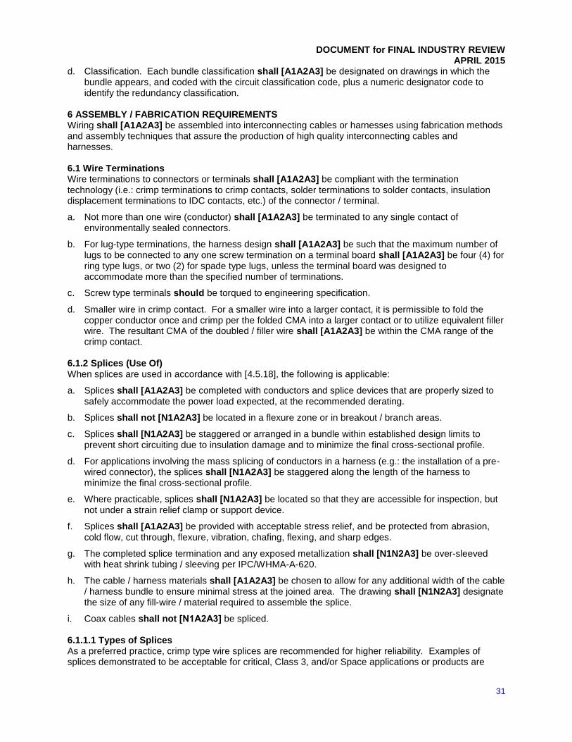
DOCUMENT for FINAL INDUSTRY REVIEW
APRIL 2015
31
d. Classification. Each bundle classification shall [A1A2A3] be designated on drawings in which the bundle appears, and coded with the circuit classification code, plus a numeric designator code to identify the redundancy classification.
6 ASSEMBLY / FABRICATION REQUIREMENTS Wiring shall [A1A2A3] be assembled into interconnecting cables or harnesses using fabrication methods and assembly techniques that assure the production of high quality interconnecting cables and harnesses. 6.1 Wire Terminations Wire terminations to connectors or terminals shall [A1A2A3] be compliant with the termination technology (i.e.: crimp terminations to crimp contacts, solder terminations to solder contacts, insulation displacement terminations to IDC contacts, etc.) of the connector / terminal.
a. Not more than one wire (conductor) shall [A1A2A3] be terminated to any single contact of environmentally sealed connectors.
b. For lug-type terminations, the harness design shall [A1A2A3] be such that the maximum number of lugs to be connected to any one screw termination on a terminal board shall [A1A2A3] be four (4) for ring type lugs, or two (2) for spade type lugs, unless the terminal board was designed to accommodate more than the specified number of terminations.
c. Screw type terminals should be torqued to engineering specification.
d. Smaller wire in crimp contact. For a smaller wire into a larger contact, it is permissible to fold the copper conductor once and crimp per the folded CMA into a larger contact or to utilize equivalent filler wire. The resultant CMA of the doubled / filler wire shall [A1A2A3] be within the CMA range of the crimp contact.
6.1.2 Splices (Use Of) When splices are used in accordance with [4.5.18], the following is applicable:
a. Splices shall [A1A2A3] be completed with conductors and splice devices that are properly sized to safely accommodate the power load expected, at the recommended derating.
b. Splices shall not [N1A2A3] be located in a flexure zone or in breakout / branch areas.
c. Splices shall [N1A2A3] be staggered or arranged in a bundle within established design limits to prevent short circuiting due to insulation damage and to minimize the final cross-sectional profile.
d. For applications involving the mass splicing of conductors in a harness (e.g.: the installation of a pre-wired connector), the splices shall [N1A2A3] be staggered along the length of the harness to minimize the final cross-sectional profile.
e. Where practicable, splices shall [N1A2A3] be located so that they are accessible for inspection, but not under a strain relief clamp or support device.
f. Splices shall [A1A2A3] be provided with acceptable stress relief, and be protected from abrasion, cold flow, cut through, flexure, vibration, chafing, flexing, and sharp edges.
g. The completed splice termination and any exposed metallization shall [N1N2A3] be over-sleeved with heat shrink tubing / sleeving per IPC/WHMA-A-620.
h. The cable / harness materials shall [A1A2A3] be chosen to allow for any additional width of the cable / harness bundle to ensure minimal stress at the joined area. The drawing shall [N1N2A3] designate the size of any fill-wire / material required to assemble the splice.
i. Coax cables shall not [N1A2A3] be spliced. 6.1.1.1 Types of Splices As a preferred practice, crimp type wire splices are recommended for higher reliability. Examples of splices demonstrated to be acceptable for critical, Class 3, and/or Space applications or products are

DOCUMENT for FINAL INDUSTRY REVIEW
APRIL 2015
32
listed in Table 4 “Types of Splices”. It is the engineer’s responsibility to choose the splice most suitable to a specific application. 6.1.2 Dead-Ending Undesignated / unterminated (i.e.: spare) wires shall [N1N2A3] be dead-ended with AS25274 caps or with insulation sleeving in compliance with IPC/WHMA-A-620, and in a manner acceptable to the User. Dead-ending shall [N1N2A3] be located within 101 to 152 mm [4 to 6 in] of connectors, breakouts, or bulkhead feed-through bushings. Dead-ending shall not [N1A2A3] be located under mounting clamps or cable identification labels. 6.1.3 Insulation Compatibility with Sealing and Servicing Wiring termination devices designed to provide an environment-resistant joint, shall [N1N2A3] be chemically compatible with the wiring insulation, and have sealing features (e.g.: elastomer grommet, cable gland, etc.) compliant with the insulation construction.
a. When the diameter of the wire is smaller than the minimum allowable diameter of the connector’s sealing grommet, a length of shrink AMS-DTL-23053/5 Class 1 & 3, /8, /11, /12 Class 3, 4, & 5, or /18 Class 2 & 3 sleeving shall [N1N2A3] be installed in back of the contact and shall [N1N2A3] protrude through the environmental seal a minimum of two (2) insulated wire diameters.
b. Elastomer grommets are generally qualified to seal on wires and electrical/optical cables having smooth extruded insulations. Only one wire/optical cable per grommet hole shall [N1N2A3] be permitted.
c. The sealing of grommets on tape wrapped, braided, striped, or other than smooth circular insulations shall [N1A2A3] be demonstrated in the qualification of the terminating device.
d. Routing and installation design shall [N1N2A3] ensure there will be no transverse (angular) loading that will degrade or compromise the integrity of the sealing feature.
Note: For technical guidance on wire to connector sealing grommet compatibility see AIR1329, “Compatibility of Electrical Connectors and Wiring”. 6.2 Form Layout Fixture A full-sized, three-dimensional (3-D) form layout fixture should be provided for all complex interconnecting cables and harnesses to ensure proper routing, wire lengths, connector configurations, support requirements, and access requirements of the wiring harnesses. The form layout fixture may be limited to partial installations which contain the more complex wiring harnesses. 6.3 Forming Wires into Cables and Harnesses Spacing dimensions for spot tie, plastic strap, and stitch lacing for trunk, branches, and breakouts shall [N1A2A3] be at increments that maintain the bundle’s desired form in accordance with IPC/WHMA-A-620.
a. When knots are staked or spot tie ends are required to be treated to prevent fraying, the necessary adhesive / doping / staking compounds, as well as any special design requirements, shall [A1A2A3] be specified on the engineering documentation.
b. Adhesive / doping / staking compounds shall [A1A2A3] be compliant with flammability and outgassing requirements.
6.4 Wire Lay Circular-constructed harness assemblies consisting of more than four (4) discrete wires or cables that are expected to be flexed during use or connector mating / demating operations shall [N1N2A3] be designed with a unidirectional or helical wire twist (lay), with the direction of twist (lay) either right or left to produce an essentially circular cross section for that portion of the wire harness or cable assembly that is subject to movement.

DOCUMENT for FINAL INDUSTRY REVIEW
APRIL 2015
33
Engineering documentation shall [N1A2A3] identify locations where harness assemblies consisting of more than four (4) discrete wires or cables are expected to be flexed during use or connector mating / demating operations and shall [N1A2A3] document the method to be used to provide the flexure (e.g, a unidirectional or helical wire twist (lay) to produce an essentially circular cross section for that portion of the wire harness or cable assembly that is subject to movement). 6.5 Bend Radius The bend radius for wires, cables, and harness assemblies shall [A1A2A3] conform to IPC/WHMA-A-620 [14.3.2], Table 14-1. For fiber optic cable, see IPC-A-610DC, Table 16-1. 6.6 Cable / Harness Management (Installation / Routing) Cables and wire harnesses should be installed / routed along flat surfaces (either vertical or horizontal) whenever possible, shall [A1A2A3] be properly supported and secured by cable clamps, and shall not [A1A2A3] be installed or routed near high electrical noise, magnetic, energy, thermal, or vibration sources that could degrade performance or reliability. The following shall [A1A2A3] be considered in the routing of cables and harnesses:
a. Provide accessibility for easy removal and replacement of attached equipment as well as the wire harness.
b. Minimize flexing and handling of the harness during installation through small structural openings.
c. Avoid interference with air ventilation flow patterns.
d. Prevent possible damage from fumes and fluids. The clearance between wires or cables and heat generating devices should be such as to avoid deterioration of wires or cable from the heat dissipated by the devices.
e. Provide slack lengths or maintenance loops sufficient for the mating / unmating of the connectors after the component / hardware has been extracted from its installed location / position, unless adequate internal access (physical and visual) is provided.
f. Wiring installations where relative movement occurs (such as at hinges, rotating pieces, vibration-isolated hardware, etc.) shall [N1N2A3] be installed or protected in such manner as to prevent deterioration of the wiring by the relative movement of the assembly parts. This deterioration includes abrasion of one wire or cable upon another, cold flow, and excess twisting, bending, and pinching. Cables and harnesses should be installed to twist instead of bend across hinges. Cables and harness assemblies in the vicinity of equipment expected to be routinely serviced or replaced shall [N1N2A3] be protected against damage caused by flexing, pulling, abrasion and other handling stress.
g. Designs of cables or wire harnesses crossing a moving or rotating interface shall not [N1N2A3] contain strain-energy elements (e.g.: springs, torsion bars, etc.).
h. The design shall [N1N2A3] ensure that cable and harness assemblies:
(1) Cannot be pinched, chaffed, or otherwise damaged by doors, lids, or slides.
(2) Will not be used as a translation device (i.e.: a hand hold, step, anchor point, etc.).
(3) Will not be bent sharply when connected or disconnected.
(4) Are readily accessible for inspection and repair.
(5) Do not infringe into the operational envelope nor constitute a safety hazard (i.e.: sagging, hooking, etc.).
(6) Are not external to the face of the equipment rack, unless otherwise required as an interface to other equipment/enclosures.
(7) Are not routed over sharp or rough edges, unless protected against damage (e.g.: abrasion, chaffing, coldflow, etc.).
6.7 Protection and Support

DOCUMENT for FINAL INDUSTRY REVIEW
APRIL 2015
34
Installed wiring harnesses and cable assemblies shall [A1A2A3] be protected and supported in accordance with IPC/WHMA-A-620. Support devices specified by the engineering drawing (i.e.: cable clamps, etc.) shall hold the wiring harnesses and cable assemblies in place without deforming or damaging the wire or cable insulation, or without causing undue mechanical strain on the connections.
a. Main Bundle Support. The main bundle shall [A1A2A3] be secured within two harness diameters (2d) of the emergence of a breakout from the main bundle, within two harness diameters (2d) following the emergence of a breakout, and at intervals not to exceed 61 cm [24 in].
b. Breakout Support. Breakouts shall [A1A2A3] be long enough to provide proper support at installation. Breakouts shall [A1A2A3] be secured by connector backshells or clamps as close to the connector as practical but shall not [A1A2A3] violate stress relief.
c. Cable Support Material. The cable support material shall [A1A2A3] be compatible with the cable material (e,g,, no adverse chemical reaction between the materials).
6.8 Etching Fluoropolymer-Insulated Electrical Wire Designs requiring the development of a mechanical bond and/or environmental seal to fluoropolymer-insulated / coated electrical wire or cable shall [N1N2A3] require the portion of the wire or cable to be wetted to be etched prior to application of adhesive / polymer.
a. Applicable: Polytetrafluoroethylene (PTFE/TFE), fluorinated-ethylene-propylene (FEP), perfluoroalkoxy copolymer (PFA), Polyvinylidene Flouride (PVDF/PVF2), and Ethylene-Tetrafluoroethylene (ETFE), Ethylene Chlorotrifluoroethylene (ECTFE)
b. Not applicable: Cross-Linked Ethylene-Tetrafluoroethylene (XL-ETFE)
c. Wet processing (chemical etching) shall [N1N2A3] be per ARP6167, “Etching of Fluoropolymer Insulations”.
d. The following shall [N1N2A3] be added to the drawing notes (when applicable):
(1) Etched surfaces shall [N1N2A3] be processed within 24 hours, or packaged and processed within two (2) years, per ARP6167, AMS2491, or equivalent process.
(2) Potting shall [N1N2A3] be accomplished within 1 year of etching, provided the etched wires have been protected from ultraviolet light and contamination.
(3) When etching of wire insulation is required to provide satisfactory bonding to potting materials, the end of the wire to be stripped and terminated shall not [N1N2A3] be exposed to the etchant. The preferred process is to form the wire into a U-shape, immersing only the bent portion in the etchant with the open end of the wire above the etchant level.
(4) The un-etched end of the wire shall not [N1A2A3] be cut off prior to neutralization of the etchant. 6.9 Identification and Marking When identification is required, the identification coding, marking methods, materials, and location/spacing shall [A1A2A3] be specified.
a. The identification code shall [A1A2A3] be printed to read horizontally from left to right or vertically from top to bottom. The characters shall [A1A2A3] be legible and permanent and the method of identification shall not [A1A2A3] impair the electrical or mechanical characteristics of the wiring.
b. Hot Stamping. Hot Stamping processes that reduce the insulation thickness below minimum requirements, reduce dielectric strength, or which reduce environmental protection or structural integrity shall not [A1A2A3] be used. Hot stamping shall not [A1A2A3] be used for optical cable.
c. Exceptions:
(1) Individual wires or cables in a jacketed or shielded-jacketed cable.
(2) Internal Wiring. Color coding or physical marking of individual conductors used in internal wiring of electronic equipment is not required.
6.9.1 Cable and Harness Assemblies

DOCUMENT for FINAL INDUSTRY REVIEW
APRIL 2015
35
Each cable and harness assembly shall [N1A2A3] be permanently marked with a unique identification code identifying the cable / harness assembly, per the detailed wire and cable specification.
a. The identification code should be printed to read horizontally from left to right or vertically from top to bottom. The characters shall [N1A2A3] be legible and permanent and the method of identification shall not [N1A2A3] impair the electrical or mechanical characteristics of the wiring.
b. When it is not possible to print directly upon a cable / harness assembly, an identification marker (i.e.: heat shrinkable sleeving, tape, etc.) should be used. The marker shall not [N1A2A3] be used as an electrical insulating device or clamp locator mark.
c. For repairable, protected harnesses, the marker shall [N1A2A3] be visible during maintenance within the accessible area at the rear of the connector.
6.9.2 Optical Cable
Optical cable shall [A1A2A3] be uniquely color-coded to facilitate identification and marked with a printed legend to identify the quantities and types of fibers within the cable (e.g.: 12 Fiber 8 x 50/125, 4 x 62.5/125). The outer cable jacket may be any color specified by the User, but the de facto industry standard, per TIA/EIA-598 is: • Orange for multi-mode (MM) • Yellow for single-mode (SM) 6.9.3 Coaxial Cable
Coaxial cable shall [N1A2A3] be identified by a colored marker of 2.5 cm [1 in] nominal width, at intervals not greater than 61 cm [24 in] of length and within 15 cm [6 in] of termination. Unless specified by the User, the color of the marker shall [N1A2A3] be solid violet (VIO, 7) in accordance with ANSI/EIA-359-A. 6.9.4 Connectors Each connector shall [N1A2A3] be permanently marked with a reference designation and unique identification code, identifying both the connector and mating receptacle, per the detailed wire and cable specification.
a. When it is not possible to mark directly upon a connector, an identification device / marker shall [N1A2A3] may be placed on the cable / harness assembly within 15 cm [6 in] of the connector; and, be of a material, either as applied or with the aid of a protective overcoat (i.e.: tape, clear shrink tubing, etc.), that will resist damage or degradation that would obscure or make the identification information illegible.
b. The reference designation and identification code should be printed to read horizontally from left to right or vertically from top to bottom. The characters shall [N1A2A3] be legible and permanent and the method of identification shall not [N1A2A3] impair mating, or the electrical or mechanical characteristics of the wiring.
c. Connector reference designations shall [N1A2A3] be assigned in accordance with the following:
(1) The movable (e.g.: less fixed) connector of a mating pair shall [N1A2A3] be identified with a “P” designation.
(2) The stationary (e.g.: more fixed location) connector of a mating pair shall [N1A2A3] be identified with a “J” designation.
(3) If two (2) cables and/or harness assemblies are to be connected to each other, each of the mating connectors shall [N1A2A3] be identified with a “P” designation.
(4) All bulkhead / rigidly mounted connectors shall [N1A2A3] be identified with a “J” designation on both sides of the structure.
(5) Connectors, such as test and power receptacles, to which a mating connector is not normally attached, shall [N1A2A3] have, in addition, the function of the connector identified.
6.9.5 Clamp Locating Marks
DOCUMENT for FINAL INDUSTRY REVIEW
APRIL 2015
36
Marking tape used to position and locate harnesses and cables may be either permanent or temporary in nature. Permanent type marking tapes shall [A1A2A3] be specified on the engineering drawing and meet M&P and environmental requirements. 7 QUALITY ASSURANCE (QA) REQUIREMENTS 7.1 Responsibility for Inspections and Tests Unless otherwise specified in the contract, the SUPPLIER shall [A1A2A3] be responsible for the performance of all inspections and test requirements as specified in IPC/WHMA-A-620 and (if applicable) IPC/WHMA-A-620X-S. The SUPPLIER may use their own facility, or any other facilities for the performance of the inspection and test requirements specified herein, unless disapproved by the User, or as otherwise specified in the contract. 7.2 Classification of Inspections and Tests The tests and inspections specified herein are classified as follows:
a. Parts, materials, and process controls
b. Physical configuration audit
c. Acceptance tests
d. Qualification tests 7.3 Workmanship, Acceptance, and Testing Workmanship, acceptance, and testing shall [A1A2A3] be specified to conform to the Product Classification specified in 1.2 and IPC/WHMA-A-620. Any deviation from, or additions to, the default requirements contained within IPC/WHMA-A-620 shall [A1A2A3] be noted on the drawing. Electrical test potentials shall not [A1A2A3] exceed the dielectric and/or current rating of the most sensitive component in the cable / harness assembly. 7.4 Qualification When required by contract, cable and wiring harness qualification may be partially or totally satisfied by qualification of higher levels of assembly that include the cable / wire harness.
a. Qualification tests shall [A1A2A3] be conducted to approved test plans that indicate what tests and test procedures will be conducted at what levels of assembly.
b. Applications having constraints on allowable outgassing shall [A1A2A3] qualify to that requirement either by test, or by an analysis using applicable materials test data to determine the estimated total mass loss and the estimated loss of volatile condensable materials for each wiring harness during its service life.
c. Applications of harnesses that cross moving or rotating interfaces shall include harness stiffness measurements and fatigue testing that may be appropriate. These tests and measurements shall [A1A2A3] be conducted under the case dimensional conditions, with maximum motion, at ambient conditions as well as under worst case design environmental conditions.
8 DOCUMENTATION Effective communication between the design and manufacturing functions is the most important element in managing the development and maintenance of any electronic product, whether it is designed and built by a company that is vertically integrated (all functions under the same organization) or if the product is being outsourced to one or multiple suppliers each of which provides a particular function or service in the development, manufacture or maintenance of the product. The degree of detail and clarity will determine the success or failure of all the factors that make up the life cycle of the end product. The documentation package should consist of multiple pieces of information (data) that fully describe the characteristics and functional performance requirements of the hardware to which the documentation pertains. This package should include functional and schematic diagrams, assembly descriptions, fabrication data (master drawing), wire lists, test requirements, specification performance control documents, and material identification descriptions / Parts Lists (PLs).

DOCUMENT for FINAL INDUSTRY REVIEW
APRIL 2015
37
Since the stages of manufacture vary, and different industry contributors need different information, the completeness of any data set should be predicated on need and updated accordingly. The revision methodology of any data set should follow proven concepts of Configuration Management and Control, thereby ensuring that there is no ambiguity as to the meaning or effectivity of information or requirements at any point during the development, design, and assembly cycles. 8.1 Data The documentation package shall [A1A2A3] be in accordance with ASME Y14.100 (incl.: sub-set Y14.24, Y14.34, Y14.35, and Y14.44); the User-specified format; or, an equivalent format agreed upon by the DESIGNER and User.
a. Straight-line Format. When practical, each wire harness or cable assembly should be presented on a separate sheet, and in a straight line (elementary) format.
b. Connection Lists. Connection lists shall [A1A2A3] list all modules / assemblies to which the cable / harness assembly is connected and identify each connection and attached wiring.
c. Critical Circuit Wiring. Circuit functions / types (i.e.: high frequency, transmission line, conducted-emission sensitive, low noise, etc.) that may be affected by wire length, routing, direction, bundling, bend radii, etc., shall [N1A2A3] be identified as critical.
d. Marking and Identification. To facilitate installation and servicing, each wiring harness or cable assembly and each connector shall [N1A2A3] be identified and physically marked with:
(1) its reference designation,
(2) the reference designation of its mating connector,
(3) the drawing part number, and
(4) a unique serial number at the time of fabrication, when specified by the User.
The method and location of the physical identification shall [A1A2A3] assure legibility when installed and shall not [A1A2A3] impair the functional characteristics of the wire harness or cable assembly.
e. Symbols. Symbols that define items on a drawing shall [A1A2A3] be consistently used. Recommended symbols include:
(1) Circle - item number
(2) Square - Note reference
(3) Vertical Triangle – Operation
(4) The initials “INT” surrounded by a rectangle – Interface dimensions. 8.2 CONNECTOR ORIENTATION (CLOCKING) Unless specified otherwise, the connector shall [N1N2A3] be depicted with the connector mating key or keyway at position 12 (“A”), with a clocking tolerance of +15 degrees. Angle type cable clamps shall [N1N2A3] be depicted at position 6 (pointing downward) as shown in Figure 8-1.
Figure 8-1 Connection Orientation (Clocking)

DOCUMENT for FINAL INDUSTRY REVIEW
APRIL 2015
38
F. Harness G. Polarizing Key Connector Orientation (Clocking) 8.3 Connector Pin-Out Unless specified otherwise on the approved drawing, the connector pin-out shall [N1N2A3] be depicted as the mating face view. 8.4 Dimensioning And Tolerance Unless specified otherwise on the approved drawing, the following shall [N1N2A3] apply:
a. Datum. Wire harness dimensions, including location of breakout points, bends, etc., shall [N1N2A3] be measured from the connector or terminator face at one end of the wire harness (DATUM).
b. Wire Harness Length. Wire harness length shall [N1N2A3] be measured from the DATUM to the final termination (i.e. connector face, terminals, splice, etc.).
c. Breakout Length. Breakout length shall [N1N2A3] be referenced from the approximate center-line of the wire harness at the breakout point to its final termination (i.e. connector face, terminals, splice, etc.).
d. Tolerance. Cable length measurement tolerance shall be as specified in IPC/WHMA-A-620, Table 11-1 “Cable Length Measurement Tolerance”, unless otherwise on the drawing / documentation. If the engineering drawing has multiple dimensions called out between a connector and termination, breakout, or overall length, the tolerances shall [N1N2A3] be considered noncumulative and will be applied to the sum of the dimensions (entire length to the termination point), not each individual dimension.
9 DEFINITIONS AND ACRONYMS For purposes of this document, the following additional acronyms, abbreviations, and terms are listed in addition to those listed in IPC-T-50, “Terms and Definitions for Interconnecting and Packaging Electronic Circuits”. 9.1 Accessories Mechanical devices, such as cable clamps or backshells, added to connector bodies. 9.2 Adapter An intermediate device to provide for attaching special accessories or to provide special mounting means. 9.3 Ambient (laboratory/test) Temperature: 15 °C to 35 °C [59 °F to 95 °F] 9.4 ANSI American National Standards 9.5 ASTM American Society for Testing and Materials 9.6 American Wire Gage A standard for expressing wire diameter. As the AWG number gets smaller, the wire diameter gets larger (i.e.: an 18 AWG conductor is twice the diameter of a 24 AWG conductor). 9.7 Barrel (Contact Wire Barrel) The section of a contact (crimp or solder) that accommodates the stripped
conductor for creating an electrical and mechanical termination. 9.8 Bend Radius The radius of a formed bend, either temporary or permanent, measured in multiples of cross-
sectional diameters, to which a component lead, conductor, cable (metallic, fiber, hybrid), harness (metallic, fiber, hybrid), optical fiber, or wire, can be bent without inducing permanent damage or reduction in performance, power, or reliability. 9.9 Bend Radius, Long-term The radius of a formed bend in a component lead, conductor, cable (metallic, fiber,
hybrid), harness (metallic, fiber, hybrid), optical fiber, or wire, in the permanently installed configuration.

DOCUMENT for FINAL INDUSTRY REVIEW
APRIL 2015
39
9.10 Bend Radius, Short-term The radius of a formed bend in a component lead, conductor, cable (metallic, fiber,
hybrid), harness (metallic, fiber, hybrid), optical fiber, or wire, during assembly, installation, or storage. 9.11 Bonding, Electrical The process by which a low impedance path for the flow of an electric current is
established between two metallic objects. 9.12 Bubble Pack A laminated plastic sheet that is formed with patterned air entrapment ("bubbles"). The bubbles
provide excellent cushioning for anything enclosed between layers of the material. 9.13 Cable, Biaxial (twin-lead) An engineered wiring product, consisting of two individually insulated 50 Ω coaxial
cables, bonded together to resemble a lamp or speaker wire. 9.14 Cable, Coaxial An engineered wiring product, typically supplied in the form of a central solid or stranded
conductor insulated by a dielectric material, held in concentric orientation to a conductive tube or braided sheath that serves both as an EMI/RFI shield and as a return circuit path. Coaxial systems are available in different technologies, ranging from flexible, insulated cable, formable, and semi-rigid metallic sheathed. 9.15 Cable, Coaxial, Flexible Flexible coaxial cable is constructed of a central solid or stranded conductor
surrounded by a flexible low loss r-f dielectric core material, which holds the inner conductor in concentric orientation to a braided metal outer conductor(s), and covered by a protective outer jacket / covering. 9.16 Cable, Coaxial, Formable / Hand-formable Formable / hand-formable coaxial cables are constructed of a
central solid conductor surrounded by a flexible low-loss r-f dielectric core material, which holds the inner conductor in concentric orientation to a tin-dipped and fused metallic braid as the outer conductor. This offers the advantage of being capable of being bent and formed without the use of tools or bending jigs, while providing the electrical signal performance of semi-rigid coaxial. 9.17 Cable, Coaxial, Semi-rigid Semi-rigid, coaxial cables are constructed of a central solid conductor surrounded
by a flexible low-loss r-f dielectric core material, which holds the inner conductor in concentric orientation to a solid, continuous, metal outer conductor (tube). 9.18 Cable, Flat An engineered wiring product, consisting of two or more individually insulated, round or flat solid
conductors that are mechanically bonded in a parallel alignment, to a flat insulating base material to form a planar composite construction. 9.19 Cable, Fiber Optic A cable containing one or more optical fibers (see figure below). The optical fiber elements
are typically individually coated with polymer layers and contained in a protective tube suitable for the environment where the cable will be deployed. 9.20 Cable, Hybrid An engineered wiring product consisting of two or more wiring technologies (i.e.: multi-
conductor, coaxial, and / or fiber optic) bound together by an overall insulation jacket (unshielded); or, bound and wrapped with an overall metallic covering (braid or foil), and covered by an overall insulation jacket (shielded). 9.21 Cable, Multiconductor An engineered wiring product, typically constructed of two (2) or more individually
insulated conductors, bound together by an overall insulation jacket (unshielded); or, bound and wrapped with an overall metallic covering (braid or foil), and covered by an overall insulation jacket (shielded). 9.22 Cable, Shielded An engineered wiring product consisting of one or more insulated conductors, wrapped with
an overall metallic covering (braid or foil), and covered by an outer insulation jacket. 9.23 Category I Circuit Power And Control Signals. Includes (a) Direct current (dc) circuits over 10 V; (b) Direct
current (dc) circuits below 10 V and over 5 A; (c) Alternating current (ac) circuits below 0.1 MHz with voltages above 25 V rms; and, (d) pulse circuits with maximum voltages above 25 V with rise and fall times greater than 1 microsecond. 9.24 Category II Circuit High Level Signals. Includes (a) digital circuits with voltage levels from 5 to 25 V maximum
and rise and fall times greater than 1 microsecond; (b) digital circuits with maximum voltage levels from 1 V to 10 V and rise and fall times less than 1 µs; (c) Alternating current (ac) circuits below 0.1 MHz with voltages between 5V and 25V, and (d) Alternating current (ac) circuits between 0.1 MHz and 1.0 MHz with voltage levels between 1V to 10V and rise or fall times less than 1 microsecond; (c) Alternating current (ac) circuits below 0.1 MHz with voltages between 5V and 25V; and, (d) Alternating current (ac) circuits between 0.1 MHz and 1.0 MHz with voltage levels between 1V and 10V.

DOCUMENT for FINAL INDUSTRY REVIEW
APRIL 2015
40
9.25 Category III Circuit Low-Level Signals. Includes (a) Direct current (dc) circuits below 10V and less than 5A; (b)
Alternating current (ac) circuits between 0.1 MHz and 1.0 MHz with voltage levels less than 1V; (c) Alternating current (ac) circuits below 0.1 MHz with voltages less than 5V; (d) digital circuits with maximum voltages less than 1V with rise times less than 1 microsecond; and, (e) digital circuits with maximum voltages less than 5V and rise and fall times greater than 1 microsecond. 9.26 Category IV Circuit Electro-Explosive Device Signals. Includes all electro-explosive device (EED) and initiator
circuits (e.g.: air bag, emergency, etc.). 9.27 Category V Circuit High-Frequency (HF) Signals. Includes (a) all Alternating current (ac) circuits above 1
MHz; (b) high level digital circuits with maximum voltages above 10V and with rise or fall times less than 1 microsecond; and, (c) Alternating current (ac) circuits between 0.1 MHz and 1.0 MHz with voltages levels above 10 V. 9.28 Circuit, Critical Signal Electrical signal circuits whose performance, reliability, and/or stability may be
adversely affected by wire length, routing, direction, bundling, bend radii, electromagnetic interference (conducted / radiated), shielding, grounding, etc. 9.29 Circuit, Power Electrical circuits dedicated to the transmission and distribution of power. Includes (a) Direct
current (dc) circuits over 10V; (b) DC circuits below 10V and over 5 A; (c) Alternating current (ac) circuits below 0.1 MHz with voltages above 25 V rms; and, (d) pulse circuits with maximum voltages above 25V with rise and fall times greater than 1 microsecond. 9.30 Circuit, Signal Electrical circuits dedicated to the transmission and distribution of low-level, high-level, and
high-frequency communications, including analog and digital format, voice and video, command and control, instrumentation and sensor data, etc. 9.30.1 Low-Level Signals Includes (a) Direct current (dc) circuits below 10V and less than 5A; (b) Alternating
current (ac) circuits between 0.1 MHz and 1.0 MHz with voltage levels less than 1V; (c) Alternating current (ac) circuits below 0.1 MHz with voltages less than 5V; (d) digital circuits with maximum voltages less than 1V with rise times less than 1 microsecond; and, (e) digital circuits with maximum voltages less than 5V and rise and fall times greater than 1 microsecond. 9.30.2 High-Level Signals Includes (a) digital circuits with voltage levels from 5 to 25 V maximum and rise and fall
times greater than 1 µs; (b) digital circuits with maximum voltage levels from 1 V to 10 V and rise and fall times less than 1 µs; (c) Alternating current (ac) circuits below 0.1 MHz with voltages between 5 V and 25 V, and (d) Alternating current (ac) circuits between 0.1 MHz and 1.0 MHz with voltage levels between 1 V to 10 V and rise or fall times less than 1 µs; (c) Alternating current (ac) circuits below 0.1 MHz with voltages between 5 V and 25 V; and, (d) Alternating current (ac) circuits between 0.1 MHz and 1.0 MHz with voltage levels between 1 V and 10 V. 9.30.3 High-Frequency Signals Includes (a) all Alternating current (ac) circuits above 1 MHz; (b) high level digital
circuits with maximum voltages above 10 V and with rise or fall times less than 1 µs; and, (c) Alternating current (ac) circuits between 0.1 MHz and 1.0 MHz with voltages levels above 10 V. 9.31 Collectable Volatile Condensable Material (CVCM) The quantity of outgassed material (volatiles) from a test
specimen that subsequently condenses on a collector maintained at a specific constant temperature for a specified time. CVCM is expressed as a percentage of the initial specimen mass. 9.32 Commercial-Off-The-Shelf (COTS) Items (i.e.: modules, assemblies, etc.) offered without modification and
available from a vendor catalog or stock for sale, lease, or license in substantial quantities in the commercial / consumer marketplace. 9.33 Connector, Backshell The rear portion of a connector assembly, designed to provide environmental protection
(i.e.: dirt, moisture, EMI, etc.) and accommodations (physical space) to provide stress relief to the wire terminations. Most backshell designs include an integral clamping device to mechanically secure the cable / wire harness to the connector. 9.34 Connector, Body The main portion of a connector assembly to which contacts and other accessories are
attached. 9.35 Connector, Grommet An elastomeric seal used on the cable side of a connector body to seal the connector
against contamination and to provide stress relief.

DOCUMENT for FINAL INDUSTRY REVIEW
APRIL 2015
41
9.36 Connector, Contact Insert The part of a connector that holds the contacts in position and electrically insulates
them from each other and the shell. 9.37 Contact, Insertable/Removable A contact that can be mechanically joined to or removed from a connector
contact insert. Usually, special tools are used to insert (lock) the contact into place or to remove it. 9.38 Contact, Pin Male-type contact designed to slip inside a socket contact.
9.39 Contact, Socket A female-type contact designed to slip over a pin contact.
9.40 Contaminant An impurity or foreign substance present in a material that affects one or more properties of the
material. A contaminant may be either ionic or nonionic.
An ionic, or polar compound, forms free ions when dissolved in water, making the water a more conductive path.
A nonionic substance does not form free ions, nor increase the water's conductivity. Ionic contaminants are usually processing residue such as flux activators, finger prints, and etching or plating salts.
9.41 Crimp A mechanical component (e.g.: terminal, splice, contact, etc.) designed to produce a permanent
electrical and mechanical termination (bond) to a conductor using a mechanical compression process. 9.42 Crimping The controlled and repeatable process of creating a permanent electrical and mechanical termination
(bond) between a crimp and a conductor by physical compression (deformation) of the crimp device and wire. 9.43 Critical Pressure Environment The localized environment created by a combination of environmental factors,
such as contamination (foreign gasses, dust particles, oxides and salts, and outgassing products), gas pressure, and temperature at which a destructive corona discharge becomes an issue, as defined by Paschen’s Law. In an air environment, this may occur at voltages greater than 190 V rms at gas pressures less than 50 Torr (0.06 atm) 9.44 Design Authority For purposes of this document, the Supplier is considered the Design Authority. (See Section
1) 9.45 Dielectric Withstanding Voltage (DWV) The maximum voltage an insulating material can withstand before
breaking down (i.e.: suffering punch-through, arcing, or voltage/current leakage). 9.46 Electrical, Electronic and Electromechanical (EEE)
9.47 Electronic Industries Association (EIA)
9.48 High Voltage (HV) There is no universally accepted definition, although the value of +6000 V is frequently cited
as the voltage level capable of resulting in permanent physiological damage to the human body under sustained contact. Incidental contact (brushing against) can produce temporary respiratory paralysis and possibly surface (arc flash) and deep tissue burns. For purposes of this document, High Voltage is defined as the voltage at which technical issues, such as creepage distance, insulation thickness, dielectric strength, corona, and geometric arrangement of conductors must be considered in the design. 9.49 Hot Swap (Electrical Function: Mate First / Break Last) A design feature of a high-availability system, where
a component or module can be connected to, or disconnected from, the system without requiring the system to be powered down. To hot swap safely, connectors with staggered pins and/or special mechanical designs are often used to ensure that electrical grounds and local power are established before other connections are made during mating, and that electrical grounds and local power are maintained until all other connections broken during unmating. 9.50 Interchangeable Item An item which possesses such functional and physical characteristics as to be
equivalent in performance, reliability, and maintainability, to another item of similar or identical purposes. An interchangeable item is capable of being exchanged for the other item without selection for fit or performance, and without alteration of the items themselves or of adjoining items, except for adjustment. 9.51 Interface Control Document or Interface Control Drawing (ICD) An interface control drawing or interface
control document (ICD) describes the interface or interfaces between sub-systems or to a system or sub-system. Interface control documents are a key element of systems engineering, as they define and control the interface(s) of a system.

DOCUMENT for FINAL INDUSTRY REVIEW
APRIL 2015
42
9.52 Institute of Electrical and Electronics Engineers (IEEE)
9.53 Intellectual Property (IP) An intangible property asset that consists of human knowledge and ideas as a result
of creativity. Measures designed to protect tangible and intangible information related to the design and manufacture of the product, include copyrights, trademarks, patents, trade secrets, etc. 9.54 Interconnecting and Packaging Electronic Circuits (IPC)
9.55 Lay The twist (helical) pattern of wire stands in a stranded wire, insulated wires in a cable, or insulated wires
and cables in a harness assembly. 9.56 Length of lay The axial length of one complete turn of the wiring helix.
9.57 Limited Life The life of a component, subassembly or assembly that expires prior to the stated lifetime.
9.58 Lock Wire See Safety Wire
9.59 Mean Time To Failure (MTTF) The expected time to failure for a non-repairable system.
9.60 Military Standard (MIL-STD) 9.61 National Aeronautics and Space Administration (NASA) 9.62 NASA Standard (NASA-STD) 9.63 Objective Evidence (OE) Documentation in the form of hard copy, computer data, video, or other media,
demonstrating that the proposed use of alternate components, materials, processes, or procedures which are not covered by, do not comply with, or which are in conflict with program-specific documents, and / or program-specified design requirements or processes are controlled and repeatable, and therefor do not represent a risk to hardware performance or reliability. Typical OE would include test reports and process control documentation demonstrating that the process is controlled (either physically or by process control) to prevent any changes in material or process following original qualification. Note that cost, schedule, hardware criticality are not considered objective evidence (OE). 9.64 Offgassing The release of a volatile part(s) from a substance when placed in a vacuum environment.
9.65 Operational Life Operational life applies to any hardware whose performance or reliability deteriorates with the
accumulation of operating time, thus requiring periodic replacement or refurbishment to maintain acceptable operating characteristics. Operational life includes usage and test. 9.66 Packaging, Handling, Storage, and Transportation (PHS&T) PHS&T describes any anticipated special
considerations for the packaging, handling, storage and/or transportation requirements for deployment and sustainment of the hardware, as well as the processes for determining these requirements. The operational environment conditions (temperature, humidity, etc.) and potential for use of hazardous materials must be considered. PHS&T requirements must be described in the systems requirements. 9.67 Qualification The test process that proves the design, manufacturing, and assembly of the hardware and
software complies with the design requirements. 9.68 Radiofrequency (RF) The frequency spectrum from 15 kHz to 100 GHz. Cables are seldom used above 18
GHz. 9.69 Radiofrequency Interference (RFI) Electromagnetic radiation in the radiofrequency spectrum from 15 kHz to
100 GHz. 9.70 Red Plague (Cu2O) The sacrificial corrosion of copper in a galvanic interface comprised of silver and copper,
resulting in the formation of red cuprous oxide (Cu2O). Galvanic corrosion is promoted by the presence of moisture (H2O) and oxygen (O2) at an exposed copper-silver interface (i.e.: conductor end, pin-hole, scratch, nick, etc.). 9.71 Red Plague Control Plan (RPCP) A documented set of process controls and material requirements to reduce
and mitigate the exposure of silver-coated copper conductors to contamination and environmental conditions that promote the development of cuprous oxide corrosion (Red Plague) and latent damage.

DOCUMENT for FINAL INDUSTRY REVIEW
APRIL 2015
43
9.72 Relative Humidity (RH) The ratio of the partial pressure of water vapor (ew) the equilibrium vapor pressure of
water (e*w) in the same volume of a gas mixture (air) at a given temperature. Relative humidity (RH) is normally
expressed as a percentage and is calculated by using the following equation: Φ = ew/e*w
9.73 Root Mean Square (a.k.a.: Quadratic Mean) (RMS or rms) A statistical measure of the magnitude of a
varying quantity that exhibits a cyclic positive and negative pattern (e.g., a sinusoid). The RMS value of a periodic electrical current is equal to the DC current that delivers the same average power to a resistor as the periodic current. 9.74 Safety Wire (Lock Wire) A type of positive locking, where a wire is threaded through a hole drilled into a
secured part (e.g.: connector, fastener, etc.), then twisted, routed, and anchored to a second part or anchor point, in a specific pattern such that any loosening of the secured part(s) or anchor point will cause an additional tightening of the safety wire - preventing further loosening or disconnection. Safety wire is a safety device, and not a means of obtaining or maintaining torque. The use of safety wire (lock wire) should be restricted to hardware that is not expected to need adjustment or removal during normal use. 9.75 Scoop-proof (connector) A physical design feature where the connector's long shell prevents inadvertent
angular cocking (misalignment) of the mating plug into the mating receptacle. This feature prevents physical damage to the pins and connector shell, reducing the possibility of electrical shorting. In the event of connector "mismates," scoop-proofing will also preclude the inadvertent partial electrical mating of differently keyed connectors. 9.76 Service Life The service life of any hardware is the sum of operational life and shelf life, minus limited life. It is
important that the design engineer realize that the actual service life may be severely impacted by the length of time the hardware is stored / inactive prior to actual use. 9.77 Shelf Life Shelf life is the period of time during which the components of a system can be stored under
controlled conditions and put into service without replacement of parts (beyond periodic servicing). 9.78 Solder Sleeve A heat-shrinkable solder termination device with meltable sealing preforms at ends.
9.79 Smart Short A sustained, higher than nominal, current flow that is under the threshold for current interruption
by the protection device. 9.80 Splice (v) The joining of two or more conductors to each other.
9.81 Stranded Conductor A conductor composed of a group of smaller wires.
9.82 System Requirements Specification (SRS) A type of program-unique specification that describes the
requirements and verification of the requirements for a combination of elements that must function together to produce the capabilities required to fulfill a mission need, including hardware, equipment, software, or any combination thereof. 9.83 Tailoring The process by which individual requirements (sections, paragraphs, or sentences) of the selected
specifications, standards, and related documents are evaluated to determine the extent to which they are most suitable for a specific system and equipment acquisition, and the modification of these requirements to ensure that each achieves an optimal balance between operational needs and cost. 9.84 Tin Pest (a.k.a.: Tin Disease / Tin Plague) The progressively destructive and irreversible allotropic
transformation of pure tin from an electrically conductive metal (a.k.a.: beta-tin / β-tin), to a crumbly, white, non-metallic, non-conductive powder (a.k.a.: alpha-tin / α-tin / white tin), when exposed to temperatures below +13 °C (+56 °F) for long periods of time. Alloying pure tin with at least 5% lead (Pb) or at least 0.5% antimony (Sb) or bismuth (Bi) is considered to be effective at preventing tin pest. 9.85 Total Mass Loss (TML) The total mass of material outgassed from a material that is maintained at a specified
constant temperature and operating pressure for a specified time. TML is calculated from the mass of the specimen as measured before and after the test and is expressed as a percentage of the initial specimen mass.

DOCUMENT for FINAL INDUSTRY REVIEW
APRIL 2015
44
9.86 Volts Direct Current (V dc) A voltage source, whose potential doesn’t vary with time (i.e.: the potential does
not switch polarity many times per second, in the shape of a sinusoidal, square, or triangular wave), and is normally provided by power supplies, generators, or batteries to power electronic circuits. 9.87 Wire Diameter (d) The outside diameter of the wire, including insulation if present.
9.88 Wire Dress The arrangement of wires and laced harnesses in an orderly manner.
Table 1 Derating (Class 3, Military Space)
NOTE 1: When wire is bundled, the maximum design current for each individual insulated wire shall be derated according to the following:
For N < 15: IBW = ISW x (29 - N)/28 For N > 15: IBW = (0.5) x ISW Where: N = number of wires IBW = current, bundled wire ISW = current, single wire
Note 2: These currents are for insulated wires in a vacuum at +94 °C [+200 °F] ambient. Note 3: Deratings listed are for insulated wire rated for +200 °C [+392 °F] maximum temperature. Derating factors for lower temperature-rated insulation shall be as follows:
a. For 150 °C wire, use 65% of value shown in vacuum column, and 80% of value shown in non-vacuum column. b. For 135 °C wire, use 45% of value shown in vacuum column, and 75% of value shown in non-vacuum column. c. For 105 °C wire, do not use this wire in vacuum environments, and use 65% of value shown in non-vacuum column.
Note 4: Maximum wire temperature for the maximum single wire current is +147 °C [+295 °F]. Note 5: These currents are for ambient (room temperature) conditions: +22 °C [+72 °F], per IPC-TM-650 [1.3]. Note 6: Wire with these currents and temperatures are not to be accessible to the User. Note 7: Wire with these currents and temperatures are not to be accessible to the User. Maximum wire temperature for the maximum single wire current: +118 °C [+242 °F]. Derating values listed apply only to round single conductors in helically wound wire bundles / cables. For derating information for ribbon cable, flat cable, and other wire types refer to the manufacturer’s recommendation.
Table 2 Summary of Circuit Categories and Shielding Requirements
Environmental Conditions
Wire Size (AWG)
Atmospheric / Non-vacuum (≥ 4.3 psia) Vacuum (< 4.3 psia)
Maximum Nominal Allowed Single Wire Current (Isw) - Amperes1, 3, 5, 6, 7
Maximum Nominal Allowed Single Wire Current (Isw) - Amperes1, 2, 3, 4
26 3.8 3.4
24 5.4 4.7
22 7.4 6.5
20 10.0 8.8
18 13.2 11.6
16 15.0 13.3
14 20.0 18.0
12 29.0 25.0
10 40.0 34.8
8 63.0 56.0
6 92.0 80.0
4 120.0 110.0
2 170.5 150.0
1/0 260.0 220.5

DOCUMENT for FINAL INDUSTRY REVIEW
APRIL 2015
45
Circuit Character Signal Level Volts (V) or Amperes (A)
Category Shielding
Direct Current (DC)
< 10 V and < 5 A IIIa Shielded as a group from other categories
< 10 V and > 5 A Ib None
≥ 10 V Ia None
Alternating Current (AC) < 0.1 MHz
< 5 V rms IIIc Shielded as a group from other categories
5 V to 25 V rms IIc Each pair shielded
> 25 V rms Ic None
Alternating Current (AC) 0.1 MHz to 1 MHz
< 1 V rms IIIb Each pair shielded
1 V to 10 V rms IId Each pair shielded
> 10 V rms Vc Coax or balanced shielded Cable
Alternating Current (AC) > 1 MHz
All Va Wave guide, coax, or balanced shielded cable
Pulse with rise or fall time > 1 µs
< 5 V peak IIIe Each pair shielded
5 V to 25 V peak IIa Each pair shielded
> 25 V peak Id None
Pulse with rise or fall time < 1 µs
< 1 V peak IIId Each pair shielded
1 V to 10 V peak IIb Each pair shielded
> 10 V peak Vb Coax or balanced shielded cable
Electro-explosive (EED) Bridge Wire Activated Device (BWAD)
All IV Each pair double-shielded

DOCUMENT for FINAL INDUSTRY REVIEW
APRIL 2015
46
Table 3 Bond Classification
CLASS FUNCTION DESIGN REQUIREMENT
C
POWER CURRENT RETURN PATH (C) - Applies to
electrical systems / designs where the hardware chassis / structure is used as the power current return.
• Used in small, self-contained systems / packages.
• NOT RECOMMENDED FOR NEW DESIGN. A dedicated power return circuit path (wire) is preferred over the use of hardware chassis / structure for power current return in large, complex, re-configurable, and distributed systems.
All circuit and systems that use the hardware chassis / structure for a power return path shall satisfy Class C bonding requirements.
• Bonding resistance requirement: Rmax = VIRmax / Imax
• Maximum allowable circuit resistance (Rmax) is determined by maximum supply current at maximum allowable voltage drop, and includes the wire, connectors, and all structural bond joints in the circuit return path.
• Design Max. Voltage Drop (VIR): <3.5% (e.g.: 28 V system ≤ 1 V; 120 V system ≤ 4 V)
• Permanent jumpers and straps acceptable.
• Cable / harness shields and/or connector shells shall not be used as the power return path.
• Requires mechanically secure bonds with low circuit impedance to assure adequate circuit power and to minimize circuit voltage drop. Improper assembly / unsecured bonds can result in loss of power, structural damage / galvanic corrosion, unintentional heating, EMC/EMI, fire, ground faults, or shock hazards to personnel.
H
SHOCK AND FAULT PROTECTION (H) - Applies to
electrical systems / designs where a dedicated circuit path (wire) is employed for power current return,
• Protects against fault currents, due to a short circuit between a power wire and a metallic component or other conductive structure that may cause electrical shock to personnel or fire hazards.
All cable and harness assemblies that use the shield as the fault current return path shall satisfy Class H bonding requirements.
• Bonding resistance requirement: ≤ 0.1 Ω)
• Design fault current: 500% overload current, 0.5 s.
• Jumpers and straps acceptable.
L
LIGHTNING PROTECTION (L) - Applies to electrical
systems / designs that would carry surge current resulting from a direct or indirect lightning strike.
• Bonding components are required to withstand high current without arcing.
• Bond strap / conductor terminations must withstand high resistive heating effects and intense magnetic forces during current pulse.
All cable and harness assemblies that could carry lightning current shall be completely enclosed in overbraid shields with a circumferential 360 degree termination into bulkhead penetrations, connectors, or connector backshells to satisfy Class L bonding requirements.
• Class L bond paths, and the joints in that path, shall have low resistance and adequate contact area to carry its share of lightning current without sustaining a burning, melting, distorting, or other heating effect due to the long duration, high-current portion of the lightning strike.
• Bonding resistance: ≤2.5 mΩ at 200 kA across any joint.
• Low inductance required. Bond strap / conductor terminations shall not be soldered.
R
ELECTROMAGNETIC OR RADIO FREQUENCY (R) -
Applies to equipment that could generate, retransmit, or be susceptible to radio frequency (RF) interference. Includes antenna mounts and cable shield connections. Provides a uniform low impedance path for all electrical equipment at radio frequencies (RF).
• Protects equipment from RF emissions.
• Direct contact preferred. No jumpers.
All Class R bond paths to structure, and the joints in that path, shall be designed such that the inductance and overall impedance, including resonances, are low enough to prevent interference at the frequencies of interest, Z=R + iωL.
• Bonding resistance requirement: ≤ 2.5 mΩElectrical connectors and their backshells used to terminate cable shields shall be installed to provide a low impedance path from the backshell to the equipment case: ≤ 2.5

DOCUMENT for FINAL INDUSTRY REVIEW
APRIL 2015
47
• Short, wide strap may be used as last resort. mΩ.
• Antennas that require low impedance to the ground plane for proper operation shall meet Class R requirements.
• Bond straps should be flat with length to width ratio less than 5:1
S
ELECTROSTATIC CHARGE (S) - Applies to conducting
items, except active antenna elements, which are subject to precipitation static effects, triboelectric charging effects, fluid flow, air flow, plasma charging, separation of elements, and/or other charge generating mechanisms.
• Protects against electrostatic discharge (ESD).
• Applies to any item subject to electrostatic charging.
• Allows moderate impedance.
All cable and harness assemblies that could accumulate a surface electrostatic charge of sufficient amplitude to damage interconnected hardware / electrical systems shall satisfy Class S bonding requirements.
• Bonding resistance requirement: ≤1 Ω)
• A mechanically secure and continuous electrical bond path that maintains specified dc resistance across the connection after exposure to shock, vibration, thermal loads, and other expected mechanical movement.
• ≤ 1 Ω: Conducting Structural Items (>100 cm2)
• ≤1000 Ω: Conductive Mechanical Subassemblies / Parts (>100 cm2)
• ≤ 1000 Ω: Non-metallic / Composite Structural Items
• Jumpers and straps acceptable.
Notes: 1. Low frequency bonds allow use of straps and jumpers. 2. High frequency bonds require low inductance paths. Short straps are sometimes acceptable. 3. High current bonds require large cross sectional areas. 4. Low current bonds allow use of small contact areas.
5. Hazardous Area Bonding - All conductive items in areas where flammable materials, gases, or vapors may be present shall have (at a minimum) a Class S electrical bond not to exceed 1.0 Ω.

DOCUMENT for FINAL INDUSTRY REVIEW
APRIL 2015
48
Table 4 Types of Splices
TABLE 5 ELECTRICAL CREEPAGE AND CLEARANCE DISTANCE
TABLE 5 ELECTRICAL CREEPAGE AND CLEARANCE DISTANCE [1]
Voltage AC or DC
Normal operating volt-ampere rating [2]
Clearance mm (in)
Creepage [3]
Open [4] mm (in)
Enclosed [5] mm (in)
0 - 64
A 1.5875 (0.0625) 1.5875 (0.0625) 1.5875 (0.0625)
B 3.175 (0.125) 3.175 (0.125) 3.175 (0.125)
C 3.175 (0.125) 9.525 (0.375) 12.70 (0.500)
65 - 150
A 1.5875 (0.0625) 1.5875 (0.0625) 1.5875 (0.0625)
B 3.175 (0.125) 6.35 (0.250) 3.175 (0.125)
C 6.35 (0.250) 19.05 (0.750) 9.525 (0.375)
151 - 300
A 1.5875 (0.0625) 1.5875 (0.0625) 1.5875 (0.0625)
B (3.175 0.125) 6.35 (0.250) 3.175 (0.125)
C 6.35 (0.250) 19.05 (0.750) 12.70 (0.500)
301 - 600 A 1.5875 (0.0625) 3.175 (0.125) 3.175 (0.125)
B 3.175 (0.125) 6.35 (0.250) 6.35 (0.250)
Splice Description Classification Assembly Difficulty Level
Termination Method
Crimp Discrete Solder
Solder Sleeve
Butt Mechanical Easy X
End Mechanical Easy X
Lap Non-Mechanical Easy X X
Lash Mechanical Moderate X X
Modified Pin Terminal (MTP) Mechanical Moderate X
Parallel Mechanical Moderate X
Jiffy Junction Mechanical Easy X
Western Union / Lineman Mechanical Difficult X X

DOCUMENT for FINAL INDUSTRY REVIEW
APRIL 2015
49
C 6.35 (0.250) 19.05 (0.750) 12.70 (0.500)
601 – 1,000
A 3.175 (0.125) 12.70 (0.500) 9.525 (0.375)
B 6.35 (0.250) 25.40 (1.000) 19.05 (0.750)
C 12.70 (0.500) 50.80 (2.000) 38.10 (1.500)
1,001 – 15,000 C [6] [6] [6]
NOTES [n]:
1. Use of electrical parts or assemblies such as potentiometers, connectors, printed wiring assemblies, and similar devices having lesser creepage and clearance distances is permissible provided these parts and assemblies conform with applicable specifications, and their energized portions are enclosed to protect against entry of dust and moisture.
2. A – Normal operating volt-ampere rating up to 50. B – Normal operating volt-ampere rating of 50 to 2,000. C – Normal operating volt-ampere rating over 2,000.
3. For top curved surfaces having a radius greater than 3 inches and for top flat surfaces, surface creepage distance shall be increased 33 percent where these surfaces have irregularities which permit the accumulation of dust and moisture.
4. Open: Equipment or parts with open enclosures in accordance with MIL-STD-108.
5. Enclosed: Equipment or parts with enclosures in accordance with MIL-STD-108, except open enclosures.
6. For voltages above 1,000 V, but less than or equal to 15,000 V, use electrical creepage and clearance values in accordance with IACS (UR) E11.
7. Original source: MIL-DTL-917F(SH), Table III

DOCUMENT for FINAL INDUSTRY REVIEW
APRIL 2015
50
APPENDIX A - MILITARY / SPACE APPLICATIONS REQUIREMENTS
Note: This appendix is not binding, unless separately and specifically included by the applicable contract, approved drawing(s), or purchase order.
STATEMENT OF STANDARD
TECHNICAL BACKGROUND
Though not officially recognized as a separate performance classification, a specialized classification for spaceflight is levied by IPC/WHMA-A-620X-S, “Space Applications Electronic Hardware Addendum to IPC/WHMA-A-620”. This classification includes products where continued high performance or performance-on-demand is critical, equipment downtime cannot be tolerated, end-use environment may be uncommonly harsh, and the equipment must survive the vibration and thermal cyclic environments experienced in military and spaceflight applications. Space and Military Avionics classification deviations to IPC-D-620 are defined and listed in Table 1 of this Addendum. A-1 GENERAL REQUIREMENTS A-1.1 Scope This Addendum provides requirements to be used in addition to, and in some cases, in place of, those published in IPC-D-620 to ensure the reliability of cable and wire harness assemblies that must survive the vibration and thermal cyclic environments of military and/or spaceflight applications. A-1.2 Purpose When required by procurement documentation/drawings, this Addendum supplements or replaces specifically identified requirements of IPC-D-620. A-1.3 Precedence The contract takes precedence over this Addendum, referenced standards and User-approved drawings (see IPC-D-620 [1.7.1]). In the event of a conflict between this Addendum and the applicable documents cited herein, this Addendum takes precedence. Where referenced criteria of this Addendum differ from the published IPC-D-620, this Addendum takes precedence. See Table 1 of this Addendum, and clauses 1.7 Order of Precedence and 1.7.1 Conflict. 1.4 Existing or Previously Approved Designs This Addendum shall not constitute the sole cause for the redesign of previously approved designs. When drawings for existing or previously approved designs undergo revision, they should be reviewed and changes made that allow for compliance with the requirements of this Addendum. 1.5 Use This Addendum is not to be used as a standalone document. Where criteria are not supplemented, Class 3 shall apply. Where IPC-D-620 criteria are supplemented or new criteria are added by this Addendum, the clause is listed in Table A1, Military / Space Applications Requirements, and the entire IPC-D-620 clause is replaced by this Addendum except as specifically noted. The clauses modified by this Addendum do not include subordinate clauses unless specifically stated (e.g., 1.4 does not include 1.4.1). Clauses, Tables, Figures, etc. in IPC-D-620 that are not listed in this Addendum are to be used as-published.
Table A1 Military / Space Applications Requirements
IPC-D-620 Reference Military / Space Requirements (as changed by this Addendum)
3.2.2.2.e Ease of Connect / Disconnect

DOCUMENT for FINAL INDUSTRY REVIEW
APRIL 2015
51
Electrical connections and cable installations shall require no more than one (1) turn to disconnect and reconnect without damage to wiring or connectors.
3.2.2.4
Service Life The design service life of a cable / wiring harness assembly shall be specified as one (1) year in addition to the expected service life of the hardware / system for which it has been designed.
4.2
Flammability Insulation materials shall be non-combustible or self-extinguishing. Selection and use shall be traceable to acceptable flammability test reports. When no test report exists, flammability testing shall be performed using the procedure of NASA-STD-6001, previously NHB 8060.1C (Flammability, Odor, Offgassing, and Compatibility Requirements and Test Procedures for Materials in Environments that Support Combustion), or as otherwise specified by the User.
4.3
Outgassing Nonmetallic materials shall not exceed 1% Total Mass Loss (TML) or 0.1% Collected Volatile Condensable Material (CVCM), when tested in accordance with ASTM E595 (Test Method, Outgassing).
4.5.10
Lead-Free Tin (<3% Pb) Technology – Control Level 2c The use of lead-free Tin (Sn) technology shall be prohibited unless documented and controlled through a User-approved Lead Free Control Plan (LFCP) in conformance with Control Level 2C requirements of GEIA-STD-0005-2, "Standard for Mitigating the Effects of Tin Whiskers in Aerospace and High Performance Electronic Systems”. See WP-015 “Lead-Free Control Plan (LFCP)” for technical guidance and requirements.
Rationale: Lead-Free Tin (<3% Pb) technology is susceptible to the spontaneous growth of electrically conductive, single crystal structures known as tin whiskers. Over time these whiskers may grow to be several millimeters (mm) long. Tin whiskers are capable of causing electrical failures ranging from parametric deviations (soft short) to sustained arcing (hard short) resulting in severe electrical and thermal damage.
4.5.18.g (New) g. Splicing of wiring in Category IV circuits, such as electro-explosive device (EED) or initiator circuits (e.g.: air bag, emergency, etc.) is prohibited on both hardware firing circuits and ground test firing circuits.
4.5.20 (New)
Parylene (Paraxylene) Coatings Containing Chlorine (Cl) Parylene-C coatings shall not be used in military applications or products without prior approval.
Rationale: (1) Parylene-C coating contains chlorine, which may corrode metals, or form undesirable electrically-conductive substances when subjected to high heat or contact with flame. (2) Outgassed products are hazardous and corrosive.
4.7.1.c c. Test connectors shall comply with the above requirements when mated with product connectors.
6.1.c
c. Screw type terminals shall be torqued to engineering specification and staked to prevent loosening. Thread locking compounds are not recommended. Adhesive / doping / staking compounds shall be compliant with flammability and outgassing requirements.

DOCUMENT for FINAL INDUSTRY REVIEW
APRIL 2015
52
6.1.1.g
g. The completed splice termination and any exposed metallization shall be over-sleeved with heat shrink tubing / sleeving per IPC/WHMA-A-620X-S. For mission critical harnesses incorporating splices, two (2) layers of shrink sleeving shall be used over the splice area. Splices shall be wrapped with protective tape to prevent cold flow of adjacent wiring and possible abrasion of shrink sleeving over the splice area.
6.1.3.c
c. The sealing of grommets on tape wrapped, braided, striped, or other than smooth circular insulations shall be subject to User approval, unless compatibility has been demonstrated in the qualification of the terminating device.
6.2
Form Layout Fixture A full-sized, three-dimensional (3-D) form layout fixture shall be provided for all complex interconnecting cables and harnesses to ensure proper routing, wire lengths, connector configurations, support requirements, and access requirements of the wiring harnesses. The form layout fixture may be limited to partial installations which contain the more complex wiring harnesses.
6.5 Bend Radius The bend radius for cables and harness assemblies shall conform to IPC/WHMA-A-620X-S [14.3.2], Table 14-1.
6.9*
Identification and Marking To facilitate the identification, isolation, modification, and repair of interconnecting wires, electrical / optical cables, wire harnesses, each wire, cable, and connector in interconnecting cables and wiring harnesses shall be permanently marked with a unique identification code. The identification coding, marking methods, materials, and location/spacing shall be specified. *This change retains all subordinate clauses.
7.5 (new)
Time-Critical or Limited-Life Cables, wiring, associated hardware, and materials which are time-critical, cycle-critical, or which have limited storage life / limited shelf life shall be stored and controlled in accordance with the material manufacturer’s recommendations, and the following additional controls: a. Special storage requirements and procedures for controlling shelf life and
shelf life extensions shall be carefully defined and strictly observed. b. Each time-critical or limited-life assembly, subassembly, component, and
spare shall be clearly and indelibly marked with a serial number. c. Appropriate documentation shall accompany all time-critical and limited-
life items and shall include the date of manufacture of the item and of its most time-critical component.
d. Realistic life limits shall be assigned and documented for each item and shall be suitably altered as new data and new evidence are obtained.
e. Operating-time logs shall be maintained for all items having limited operating lives (e.g.: connector mating).
A time-age-life cycle database shall be maintained for verification (and notification) of time-age-life component status. Status records shall be maintained on all such items after installation.

DOCUMENT for FINAL INDUSTRY REVIEW
APRIL 2015
53
Appendix B - ELECTRICAL WIRE AND CABLE ACCEPTANCE TESTS
Note: This appendix is not binding unless separately and specifically included by the applicable contract, approved drawing(s), or purchase order.
STATEMENT OF STANDARD
Electrical wire and cable, including wiring used within containerized electrical / electronic assemblies ("black boxes") shall be procured and acceptance tested to the appropriate cable specifications listed below:
a. Cable specification ANSI/NEMA WC 27500, Standard for Aerospace and Industrial Electrical Cable.
b. Cable specification MIL-C-17, Cables, Radio Frequency, Flexible and Semi-rigid.
c. Wire specification AS22759, Wire, Electrical, Fluoropolymer Insulated Copper or Copper Alloy
d. Other wire procurement specifications may be authorized by the User.
e. Wire and cable shall also comply with applicable Materials and Process (M&P) requirements.
If the wiring used in any application is unknown, as it may be in the case of off-the-shelf equipment, pig-tailed components, heater strips, etc. and if the application is non-critical, the assembly is required only to meet applicable program materials and process requirements.
Two methods for certifying wire are: a. As required by the procurement specification, Government Source Inspection (GSI) shall certify that
the test specified below has been performed by the wire manufacturer on the length of wire procured. In addition to meeting the requirements of the appropriate procurement specification, each shipment shall be accompanied by the manufacturer’s test report.
b. Wire certification can also be performed by a User-approved test facility.
In either case, testing shall consist of the tests below. Testing for insulation flaws of cable’s basic wires shall be done prior to cable assembly. 100-Percent Testing a. Insulated single conductor wires and cable basic wires
(1) Impulse dielectric test (no greater than 80% of military specification) b. Cable
(1) Dielectric withstand of component wires (2) Jacket flaws for shielded cables
Sample Testing As a minimum, a sample or samples of each lot of wire/cable shall be subjected to the following applicable quality conformance inspections. (Applicability is determined by the specifications cited above). a. Insulated single-conductor wires and cable basic wires
(1) Conductor resistance (2) Wrap test (3) Shrinkage (heat resistance) (4) Cold bend followed by wet dielectric (5) Visual and mechanical examination (finished wire O.D., identification of product, conductor
diameter, strand diameter, conductor stranding, wire base metal, and the plating material) (6) Polyimide cure test (applicable to modified aromatic polyimide coatings only) (7) Cross-link proof testing for cross-linked insulation materials

DOCUMENT for FINAL INDUSTRY REVIEW
APRIL 2015
54
b. Cable (1) Shield coverage (2) Identification of product (3) Jacket wall thickness (4) Cold bend (5) Thermal shock (6) Stress-Crack Resistance testing (MIL-C-17 Cable only)
Any failure during sample testing shall be cause for immediate rejection of the entire lot. Certification Processes Certification of a User-approved test facility is done by an audit team with representatives from the User, or their representatives. The team shall assure the test lab is qualified to perform the test methods referenced in this standard. At the using installation, before placing wire/cable into bonded storage, representatives from the Engineering team and/or receiving inspection function shall verify that the test report indicating conformance with all applicable procurement specification requirements accompanies each lot shipped. Storage shelf life: Silver-coated copper wire and cable that has exceeded a shelf life of ten (10) years from manufacturing date shall not be used on assemblies fabricated to this standard. Remarks The primary reason for downgrading silver-coated wire after ten (10) years of age is to control increased solderability problems and the potential for Red Plague for wire stored in a high moisture environment.

DOCUMENT for FINAL INDUSTRY REVIEW
APRIL 2015
55
APPENDIX C - BEND RADIUS Note: This appendix is not binding, unless separately and specifically included by the applicable contract, approved drawing(s), or purchase order. STATEMENT OF STANDARD
Conductor / Cable Type Optimum Bend Radius (O.D.) [1]
Minimum Bend Radius (O.D.) [1]
Space between constraint point to start of bend (O.D.) [1], [4]
Bare bus or enamel-insulated wire 3 2 2
Cat5 Ethernet 10 4 2
Coaxial Cable, Flexible [2] 10 6 6
Coaxial Cable, Fixed [3] 10 6 6
Coaxial Cable (Rigid) 3.5 2 6
Coaxial Cable (Semi-Rigid) 3.5 2 6
Component Lead (Flat) 2 1 0.5 mm [0.020 in]
Component Lead (Round) 2 1 2
Fiber Optic Cable 15 10 10
Fiber Optic Cable (Hybrid) 20 10 10
Fiber Optic, Individual (Tight Buffer / jacketed) 15 10 10
Flat Cable 10 3 3
Flat Cable (Shielded) 10 3 3
Harness (with individual conductors 8 AWG or larger, coaxial cable or optical fiber) [6] [7]
10 6 6
Harness (with individual conductors 10 AWG or smaller; no coaxial or optical fiber) [8]
10 3 3
Harness with polyimide (Kapton®) insulated wires [6] 15 10 10
Individual Insulated Conductor 3 2 2
Individual Insulated Conductor, Composite (TK / TKT) Insulation [7] (AS22759/80-/92)
10 6 6
Multi-conductor Cable (Non-Shielded) 10 3 3
Multi-conductor Cable (Shielded) 10 6 6
Polyimide (Kapton®) Insulated – FN or HN Grade MIL-W-81381/07- /22
15 10 10
Polyimide (Kapton®) - T Grade 15 10 10
Ribbon Cable 10 3 3
Ribbon Cable (Shielded) 10 3 3
Shield / drain wire [5] 3 3 2

DOCUMENT for FINAL INDUSTRY REVIEW
APRIL 2015
56
Notes [n]: 1. OD is the outer diameter of the wire / cable / harness assembly, including insulation / jackets / shielding. 2. Coaxial Cable (Flexible) - Coaxial cable that is or may be flexed during operation of the equipment. 3. Coaxial Cable (Fixed) - Coaxial cable that is secured to prevent movement; not expected to have the cable
repeatedly flexed during operation of the equipment. 4. Distance from the entrance/exit of the connector or connector accessory, strain relief, tie/strap, support
clamp, or breakout and start/end of the bend (measured as outside of the bend radius). 5. Wires used as shield terminators or jumpers that are required to reverse direction in a harness. Bend
radius is measured at the point of reversal plus constraint dimension, providing the wire is adequately supported.
6. Any insulation type, including composite (TK or TKT) construction. 7. Does not include polyimide (Kapton®) insulation grade FN, HN, or T 8. Does not include composite (TK or TKT), or polyimide (Kapton®) insulation FN, HN, or T 9. AS22759/80-/92 10. Oasis ®