final presentation phase 1 analysis and definition of the ... · pdf file06/02/2009 d.mignolo...
TRANSCRIPT
06/02/2009 D.Mignolo TIA-TF 1
ESTEC - Noordwijk 6th Feb. 09
Final Presentation Phase 1
Analysis and Definition of the Satellite System (Phase A)
Introduction
06/02/2009 D.Mignolo TIA-TF 2
Outline PresentationOutline Presentation
• Satellite studies tasks description • Study logic and execution• Communication study input for Task 2• ESA Link Budget for Task 3• Conclusions
Satellite System Studies Satellite System Studies DescriptionDescription
06/02/2009 D.Mignolo TIA-TF 4
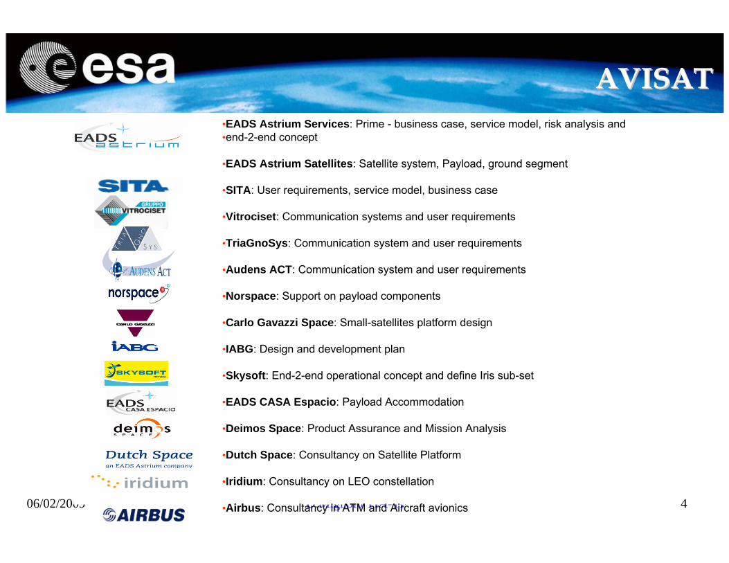
AVISATAVISAT•EADS Astrium Services: Prime - business case, service model, risk analysis and •end-2-end concept
•EADS Astrium Satellites: Satellite system, Payload, ground segment
•SITA: User requirements, service model, business case
•Vitrociset: Communication systems and user requirements
•TriaGnoSys: Communication system and user requirements
•Audens ACT: Communication system and user requirements
•Norspace: Support on payload components
•Carlo Gavazzi Space: Small-satellites platform design
•IABG: Design and development plan
•Skysoft: End-2-end operational concept and define Iris sub-set
•EADS CASA Espacio: Payload Accommodation
•Deimos Space: Product Assurance and Mission Analysis
•Dutch Space: Consultancy on Satellite Platform
•Iridium: Consultancy on LEO constellation
•Airbus: Consultancy in ATM and Aircraft avionics

06/02/2009 D.Mignolo TIA-TF 5
SAMARASAMARA
Thales Alenia Space Italia S.p.A.
Thales Alenia Space Espana
Thales Alenia Space France SAS
TAS-I: Prime - System requirements, Satellite System Design, ATM payload Baseline Design, Ancillary Payload Baseline Design, Business case contribution, Cost Estimate, Safety and Dependability Analysis
TAS-F: Satellite System Design contribution, EGNOS ancillary payload design, support on Cost Estimate, Risk Management Plan,
TAS-E: ATM repeater design and costing, Ground to Ground Ancillary Payload design
SELEX: Operational Concept, Service Model, Business Case contribution
OHB: Small satellite platform Design, Payload accommodation and system data provisioning
INDRA: Satellite Ground Control Segment definition, Space System Operational Concept
AIRTEL: Analysis of commercial and institutional needs, Analysis of enduser requirements and standards, Space System Operational service plan
NPO-PM: Highly Elliptical Orbit satellite option initial design & Payload accommodation
CONPLAN: Business Case analysis
FREQUENTIS: Certification analysis

06/02/2009 D.Mignolo TIA-TF 6
Satellite Studies main objectivesSatellite Studies main objectives
• Propose options for the space segment• Propose a deployment strategy• Identify operational concept and service model• Propose business case options • Analyse issues related to certification, safety and risk• Identify all system elements required to validate the
communication standard (subset)
Study Logic and Execution Study Logic and Execution

06/02/2009 D.Mignolo TIA-TF 8
Study Logic and ExecutionStudy Logic and Execution
TASK 1TASK 1 Space Segment Architecture options
System Requirement
TASK 2TASK 2Link budget
Capacity
ICOS payload (options)Phoenix payload (options)
Payload with reduced capacityPreliminary Costs Analysis
TASK 3TASK 3Link budgetCapacity requirements)
(optimization)
Input Studies Outcome
Refined designed of each space segment optionCost Analysis
Dependability analysisService model and Business case
Certification analysisRisk analysis
PHOENIX&
ICOSStudies
ESA
ESA

06/02/2009 D.Mignolo TIA-TF 9
Study Logic and ExecutionStudy Logic and Execution
• Both consortia have proposed space segment options for each Phase A communication studies air interface
• Solutions differ due to different assumptions taken by each consortium:– Capacity (traffic to be accommodated)– Communication performances (data rate and access scheme)– Geographical Coverage– Link Budget
• A large range of payload options has been analyzed showing the impact (costs, performances, complexity) of different assumptions on the overall space segment.
• Each consortium has been defined a deployment strategy leading to full operational system by 2020
• Each consortium has designed a payload with reduced capacity that could contribute to the operational system architecture
• Costs for the operational system have been derived and used in the Business Case options analysis

Communication study input for Task 2Communication study input for Task 2(Preliminary Design)(Preliminary Design)

06/02/2009 D.Mignolo TIA-TF 11
Coverage requirementsCoverage requirements
System Requirement Document Geographical coverage requirements:•ECAC coverage as main target (up to 70 deg latitude) •Polar coverage as potential extension•Global beam for Oceanic and Remote areas (i.e. visible Earth from GEO orbit) as potential extension
ECAC TerritoryTarget Coverage

06/02/2009 D.Mignolo TIA-TF 12
Phase A studies propose either 3 or 6 spotbeams to cover ECAC
Spot beams coverage optionsSpot beams coverage options
Phoenix ICOS
06/02/2009 D.Mignolo TIA-TF 13
Data Rates Data Rates
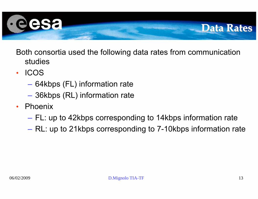
Both consortia used the following data rates from communication studies
• ICOS– 64kbps (FL) information rate– 36kbps (RL) information rate
• Phoenix– FL: up to 42kbps corresponding to 14kbps information rate– RL: up to 21kbps corresponding to 7-10kbps information rate

06/02/2009 D.Mignolo TIA-TF 14
Capacity and performancesCapacity and performances
• Capacity and link budget provided by each communication study as input for Task 2 preliminary payload design
ECAC + GlobalThroughput=3.1 MbpsG/T= Spots 2.5 dB/K; G/T Regional -4.5 dB/K
ECAC Throughput=2.1MbpsGlobal Throughput= 1.MbpsG/T= -1dB/KReturn Link
ECAC+GlobalThroughput=5.3MbpsEIRP=41.7dBW single carrier
ECAC Throughput=2.9MbpsGlobal throughput= 1MbpsEIRP=46 dBW single carrierForward Link
PHOENIXICOS
ESA Link Budget for Task 3ESA Link Budget for Task 3(Space Segment Refinement)(Space Segment Refinement)
06/02/2009 D.Mignolo TIA-TF 16
ESA Link BudgetESA Link Budget
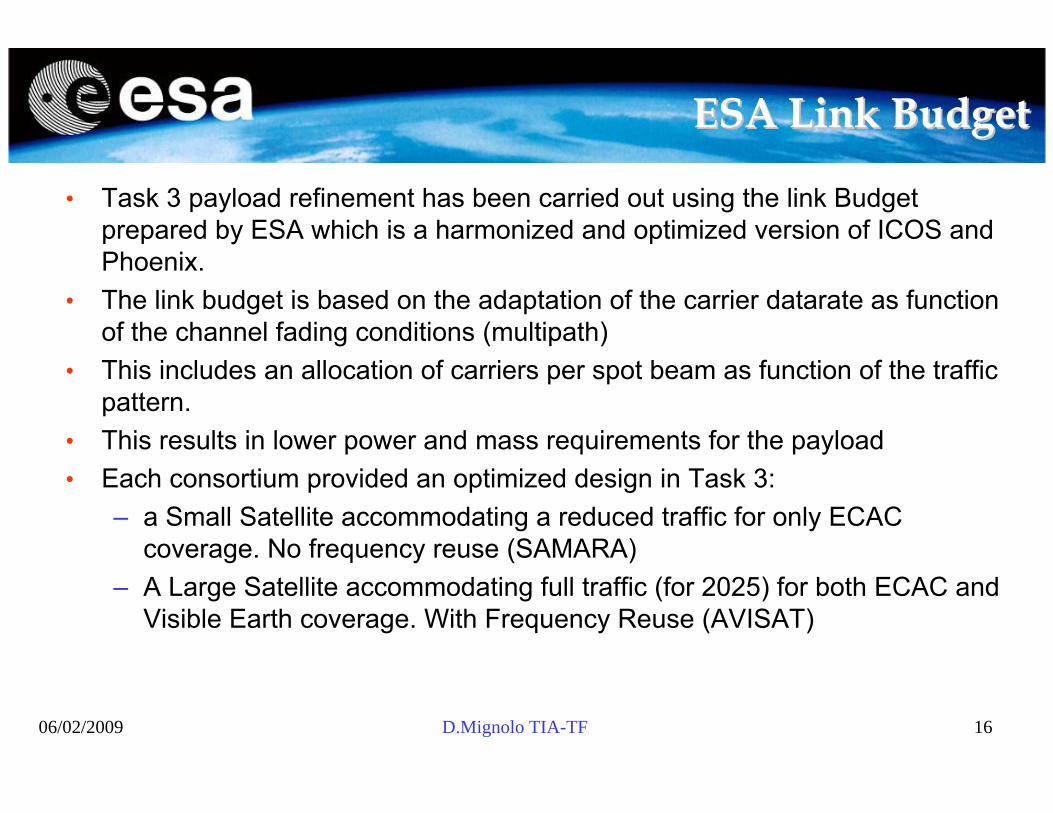
• Task 3 payload refinement has been carried out using the link Budget prepared by ESA which is a harmonized and optimized version of ICOS and Phoenix.
• The link budget is based on the adaptation of the carrier datarate as function of the channel fading conditions (multipath)
• This includes an allocation of carriers per spot beam as function of the traffic pattern.
• This results in lower power and mass requirements for the payload• Each consortium provided an optimized design in Task 3:
– a Small Satellite accommodating a reduced traffic for only ECAC coverage. No frequency reuse (SAMARA)
– A Large Satellite accommodating full traffic (for 2025) for both ECAC and Visible Earth coverage. With Frequency Reuse (AVISAT)

06/02/2009 D.Mignolo TIA-TF 17
ESA Link BudgetESA Link BudgetMain Link Budget Assumptions• Access Scheme
– TDM in Forward Link– TDMA in Return Link
• Physical Layer– QPSK Modulation– Turbo Codes ½ code rate– 80 ms interleaver– Target PER = 10-3– Required Eb/No = 3 dB
• Multipath Margins– Forward Link
» 7.4 dB, for 5 deg ≤ elevation < 10 deg » 5.4 dB, for 10 deg ≤ elevation < 15 deg» 3.2 dB, for 15 deg ≤ elevation
– Return Link» 6 dB, for 5 deg <= elevation < 10 deg » 4 dB, for 10 deg <= elevation < 15 deg» 2.6 dB, for 15 deg <= elevation
• Ionospheric Scintillations Margin: 1.6 dB
06/02/2009 D.Mignolo TIA-TF 18
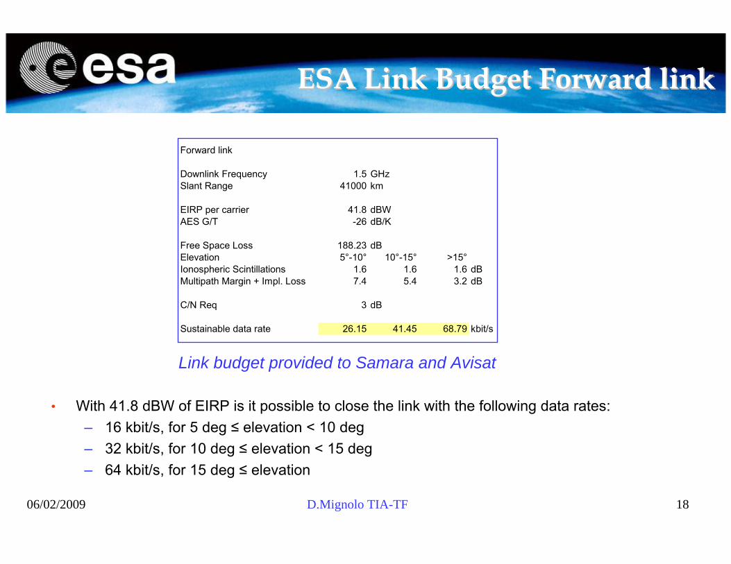
ESA Link Budget Forward linkESA Link Budget Forward link
• With 41.8 dBW of EIRP is it possible to close the link with the following data rates:– 16 kbit/s, for 5 deg ≤ elevation < 10 deg – 32 kbit/s, for 10 deg ≤ elevation < 15 deg– 64 kbit/s, for 15 deg ≤ elevation
Link budget provided to Samara and Avisat
Forward link
Downlink Frequency 1.5 GHzSlant Range 41000 km
EIRP per carrier 41.8 dBWAES G/T -26 dB/K
Free Space Loss 188.23 dBElevation 5°-10° 10°-15° >15°Ionospheric Scintillations 1.6 1.6 1.6 dBMultipath Margin + Impl. Loss 7.4 5.4 3.2 dB
C/N Req 3 dB
Sustainable data rate 26.15 41.45 68.79 kbit/s

06/02/2009 D.Mignolo TIA-TF 19
ESA Link Budget Return linkESA Link Budget Return link
Return link
Uplink Frequency 1.6 GHzSlant Range 41000 km
AES EIRP 13.5 dBW
Free Space Loss 188.79 dB
Transponder G/T 4.5 dB/KElevation 5°-10° 10°-15° >15°Ionospheric Scintillations 1.6 1.6 1.6 dBMultipath Margin + Impl. Loss 6 4 2.6 dB
C/N Req 3
Sustainable data rate 52.65 83.45 115.20 kbit/s
Link budget provided to Avisat
Return link
Uplink Frequency 1.6 GHzSlant Range 41000 km
AES EIRP 13.5 dBW
Free Space Loss 188.79 dB
Elevation 5°-10° 10°-15° >15°Antanna Gain at AES location EOC EOC + 1 dB EOC + 2 dBTransponder G/T -1 0 1 dB/KIonospheric Scintillations 1.6 1.6 1.6 dBMultipath Margin + Impl. Loss 6 4 2.6 dB
C/N Req 3
Sustainable data rate 14.84 29.61 51.46 kbit/s
Link budget provided to Samara
ConclusionsConclusions

06/02/2009 D.Mignolo TIA-TF 21
Conclusions (1/2)Conclusions (1/2)
• Use of Low Gain Antenna on board aircraft drives the overall Payload sizing
• 2 satellites in hot redundancy are required to meet target spacesegment reliability
• For the full operational system a medium size platform (e.g. SB4000 B2, E3000) is required due to power constraints.
• A Large antenna (>5m) is required to implement frequency reuse.
• If WXGRAPH service could be implemented in multicast, the required payload would be smaller and could be accommodated on a smaller platform (e.g. Small GEO)
06/02/2009 D.Mignolo TIA-TF 22
Conclusions (2/2)Conclusions (2/2)
• Most of the ECAC air-traffic is concentrated between AMS, LON, PAR, ROM, which are all in the same spot beam– the adoption of frequency reuse on ECAC would not result in
major spectrum savings unless very small beams are used, This would require a very large antenna.
• Visible Earth coverage would require frequency reuse leading to a large satellite with a very large antenna
• Provide high latitude coverage (5 deg elevation angle) with highdata rate (e.g. 64 kbps) would require large payloads (single carrier EIRP 45dBW).