final report a small, single stage orifice … · part. prepared for: national aeronautics ... p.o....
TRANSCRIPT

HASA-CR-190_,9
FINAL REPORT
SBIR- 08.03-8629A
release date 3/02/92 v_.
A SMALL, SINGLE STAGE ORIFICE PULSE TUBE CRYOCOOLER DEMONSTRATION
CONTRACT NO. NAS7-I031
CONTRACT PERIOD: MARCH 2, 1988 THROUGH AUGUST 2, 1990
NOTICE: RIGHTS IN DATA SBIR PHASE II (APRIL 1985)
This SBIR data is furnished with SBIR rights under the NASA Contract No.
NAS7-I031. For a period of two years after acceptance of all items to be
delivered under this contract the Government agrees to use this data for
Government purposes only, and it shall not be disclosed outside the Government
(including disclosure for procurement purposes) during such period without
permission of the Contractor, except that, subject to the foregoing use and
disclosure prohibitions, such data may be disclosed for use by support
Contractors. After the aforesaid two-year period the Government has aroyalty-free license to use, and to authorize others use on its behalf, this
data for Government purposes, but is relieved of all disclosure prohibitions
and assumes no liability for unauthorized use of this data by third parties.
This Notice shall be affixed to any reproductions of this data, in whole or inpart.
PREPARED FOR:
NATIONAL AERONAUTICS AND SPACE ADMINISTRATION
JET PROPULSION LABORATORY
PASADENA, CA
PREPARED BY:
DR. JOHN B. HENDRICKS, PRINCIPAL INVESTIGATOR
DR. MYRON E. CALKINS, PROJECT SCIENTIST
ALABAMA CRYOGENIC ENGINEERING, INC.P.O. BOX 2470
HUNTSVILLE, AL 35804
AUGUST 30, 1990
C_,',_-:,-C -! ,C,: _ ;} ?, Du>.LL, <:i_._.! !
_T>_ : "iF ! r P!JL'] TU; " c. ,V ;C L ',
Li I
%
.... _!/!: i
% , _-] ]c+i_
ij_,C | ;:,
",_ ) •
https://ntrs.nasa.gov/search.jsp?R=19930004216 2018-07-15T03:59:53+00:00Z

A SMALL, SINGLE STAGE ORIFICE PULSE TUBE CRYOCOOLER DEMONSTRATIONCONTPJ_CT NO. NAS7-I031
Project Summary
The principal objective of this effort was: "The demonstration of a 0.25 Watt,
80 Kelvin Orifice Pulse Tube Refrigerator." Such a refrigerator has numerouspotential scientific, military, and commercial applications.
This program has produced the following results:
a. A partially optimized pulse tube refrigerator has been developed
that demonstrates an ultimate temperature of 77K, has a projected
cooling power of 0.18 Watts at 8OK, and a measured cooling power ofI Watt at g7K, with an electrical efficiency of 250 Watts / Watt,
much better than previous pulse tube refrigerators.
be A model of the pulse tube refrigerator has been developed that
provides estimates of pressure ratio and mass flow within the pulsetube refrigerator, based on component physical characteristics.
C° A model of pulse tube operation
generalized analysis. This model
optimization of existing designs.
has been developed based on
is adequate to support local
d ° A model of regenerator performance has been developed based on an
analogy to counterflow heat exchangers.
The analytical and experimental work in this program supports the followingconclusions.
a. Practical pulse tube refrigerators with cooling powers in the rangeof 0 to 2 Watts are possible, and may be expected to exhibit
specific inputs in the 100-250 Watts/Watt range at 90-I00K andpossibly as low as 70-80K.
be Practical pulse tube refrigerators can be designed and built by
starting with an initial cut and try design, and using the tools
developed in this effort to support local modeling and optimizationto develop the final design.
Potential commercial applications include:
a. Long lifetime remote sensing applications.
b° Cry,coolers for Magnetic Imaging and Magnetic Resonance Imaging
Systems where the very low vibrational and magnetic signatures ofthe pulse tube cry.cooler are desirable.
Co Simple, high efficiency, high reliability pulse tube refrigerators
have the potential to replace current Split-Stirling cry.coolers in
numerous applications in space, military, scientific, and commercialapplications.
PREPARED BY: DR. JOHN B. HENDRICKS, PRINCIPAL INVESTIGATOR
DR. MYRON E. CALKINS, PROJECT SCIENTIST
ALABAMA CRYOGENIC ENGINEERING, INC., (205) 536-8629P.O. BOX 2470, HUNTSVILLE, AL 35804

Section
I ,
TABLE OF CONTENTS
INTRODUCTION ................................................. I
1.1 Introduction to Pulse Tube Refrigerators ................ 3
1.2 Overview of Analytical Progress ......................... 6
1.3 Overview of Experimental Progress ....................... 8
2. THEORETICAL AND EXPERIMENTAL STUDIES ......................... 11
2.1 Compressor and System Model ............................. 11
2.2 Pulse Tube Model ........................................ 29
2.2.1 Generalized Analysis ............................. 302.2.2 Application of Generalized Analysis to Pulse Tubes 36
2.3 Regenerator Model ....................................... 47
2.4 Experimental Studies and Results ........................ 61
2.4.1 The Regenerator Test Facility .................... 612.4,2 The Pulse Tube Test Facility ..................... 642.4.3 Early Studies .................................... 712.4.4 Studies with the 20cc Pressure Wave Generator .... 73
3. CURRENT PROTOTYPE ............................................ 81
3.1 Physical Description .................................... 82
3.2 Analytical Predictions .................................. 83
3.3 Measured Performance .................................... 84
4. CONCLUSIONS .................................................. 91
5. RECOMMENDATIONS .............................................. 93
6. REFERENCES ................................................... 94
ii

Use or disctosure of data is subject to the restriction on the cover page of this report.
1.0 INTRODUCTION
The principal objective of this effort was:
"The demonstration of a 0.25 Watt, 80 Kelvin Orifice
Pulse Tube Refrigerator."
The program has been successful in meeting this objective. As discussed, an
Orifice Pulse Tube Refrigerator has been demonstrated that reaches an ultimate
temperature of 77 K, provides I Watt of cooling power at 97 K and is estimated
to provide 0.2 W of cooling power at 80 K. It does so with a net electrical
efficiency greater than previous versions of the Orifice Pulse Tube, as shown
in figure 1.0-I.
In achieving this success, the analytical and experimental tasks have been
strongly driven by experimental necessity and results. Early progress was
attributable more to cut-and-try experimental approaches than to analytical
design. Design and analysis tools existing at the beginning of the effort
proved grossly unequal to the task of establishing an acceptable a-priori
design. New analysis and design tools have been developed as an outgrowth of
experimental success. These tools do not yet provide fully analytic design
capability, but have been demonstrated to support local optimization of
substantially acceptable baseline designs.
A secondary objective of the program was to produce a prototype Orifice Pulse
Tube Refrigerator that conformed to the envelop
Split-Sterling refrigerator(CTI-Cryogenics model CM-5).
I
of the "standard"
This objective was

A
I=
I.
c:m_
u
miI
I
u_
600
5OO
400
300
200
100 t0
0
D
O
Radebaugh1.2 MPa
1.7 MPa pt
/
_ J--_/ 100 K
I
9OK.
• I00 K
llOK
b
10 20 30
Frequency (Hz)
Figure 1.0-I. Specific power as a function of operating frequency for
several different pulse tube cryocoolers. The data from
Radebaugh (continuous curve) are for a temperature of 80K,
and a pressure of 2 MPa. The isolated points are for the
present effort. The points at 19 Hz are at a pressure of 1.7
MPa, those at 22 Hz are at a pressure of 1.2 MPa. Temperatures
at which these levels of performance are achieved are indicated
on the graph.

Use or disclosure of data is subject to the restriction on the cover page of this report.
not met. The initial rationale for the effort to build a pulse tube within
the SplitoStirling envelop was that although the pulse tube offers better
reliability than the Stirling cycle systems, it was not expected to have as
high a coefficient of performance, and the replacement of Stirling systems
would be based primarily of a power/reliability tradeoff. Estimates of the
volume efficiency of the pulse tube system indicate that it may actually be
impossible to develop a unit to fit within the Stirling envelop, since (as
discussed in section 2.2), the pulse tube is constrained to operate at lower
pressure ratios than the Stirling cycle machines, and makes less effective use
of the average mass flow. However, present data indicates that the specific
power consumption of the current prototype rivals that of the Stirling,
justifying a trade of the larger volume requirements of the pulse tube
refrigerator against the lower reliability of the Stirling cycle machines.
This report is divided into five sections. The remainder of the introduction
provides a short background discussion of the pulse tube. The second section
details analytical and experimental progress and results. The third section
describes the current experimental prototype. Conclusions are presented in
the fourth section, and recommendations in the fifth.
1.1 Introduction to Pulse Tube Refriqerators
An excellent recent review of the status of research on pulse tube
refrigerators is provided by Radebaugh (1990). This introduction borrows
heavily from that source. Pulse tubes were first developed by Gifford and
Longsworth (1963), and presently exist in three variants, the basic pulse
tube, the resonant pulse tube, and the orifice pulse tube used in the present
3

Use or di$ctosure of data" is subject to the restriction on the cover page of this report.
effort. A fourth recent variant, the double inlet pulse tube has been
reported by Shaowei, et.al. (1990). An excellent comparison of all the pulse
tube types except the double inlet pulse tube is provided by Radebaugh (1986).
As shown in figure 1.1-I, all pulse tubes rely on the periodic compression of
gas in a hollow tube connected to a regenerator. In addition, the orifice
pulse tube has an orifice and associated orifice volume at the warm end of the
pulse tube, while the double inlet pulse tube has additional valving and what
amounts (in one form or another) to a phase shifting network between the
compressor and the warm end of the pulse tube.
The basic pulse tube (Longsworth, 1967) operates at frequencies well below the
resonant frequency of the tube, and appears to be limited to temperatures
above about 120K. The resonant pulse tube (Wheatley, 1985) operates at the
resonant frequency of the tube, and has reached temperatures as low as 195K.
The orifice pulse tube was developed by Mikulin et. al. (1984) and has reached
an ultimate temperature of 49K (Jintao Liang, et al., 1990).
The thermodynamic cycle of the pulse tube may be thought of (very
approximately) as the midpoint between an adiabatic Ericsson and an adiabatic
Stirling cycle. Compression and expansion are approximately adiabatic while
heat absorption and rejection occur in the realm between constant pressure and
constant volume (see section 2.2 for more details).

o)
E/Regenerator
wl
i
iF--
//i/
//'.I,//._•///
///i
Piston
Heat
Exchanger
__OH
ii
Pulse Tube
i
heel
J : Excnonge_i
Piston
W
b) ir.
[
_Qo
Regenerator F//
k_//,
Reservoir
Volume
Orifice
ZIX
Heat
Exchanger
WmI_ --o.
Pulse Tube
Heat
', Exchanger
i
W i Reservoir
Volume Ic) lvL
!
I 1 ,' Orifice/
O o _ _ HeetI_---'_-_/_ Exchanger
I>./S_; I I,,",S,S2J !F, ,'/,-" , i
V, .-_.4 I I Pulse TubeRegenerator k,, "//_. I II,_,/V, 2t
_"//d i i
J Exchanger
Figure 1.1-I Three types of pulse tube refrigerator; a) basic pulse tube
b) orifice pulse tube, and c) double inlet pulse tube.

Use or disclosure of data is subject to the restriction on the cover page of this report.
1.2 Overview of Analytical Progress
At the beginning of the present effort, the analytical models of the pulse
tube refrigerator, the pulse tube itself, and the regenerator were those
presented in the proposal. These models were believed to provide an adequate
theoretical and predictive framework to develop a-priori designs of acceptable
pulse tubes. This proved to be wrong. Although the models provided some
insight into the operation of the pulse tube, they did not permit a-priori
design, and did not permit even local optimization of existing designs.
To replace these inadequate models, further analytical development was
required. In the case of the system model, it was found that a very simple
and straightforward model was sufficient to predict pressure ratios and mass
flows accurately enough to drive the more detailed models of the regenerator
and pulse tube that were also developed.
The model of the pulse tube that emerged was "Generalized Analysis", and is
based on a correction and extension of existing work by Rallis, and extended
by Walker (1979), and further discussed in the book (Walker, 1983). This
model provides performance estimates for pulse tubes themselves, based on the
working fluid, the pressure ratio Rp, the heating loads, and the efficiency of
the regenerator. This model appears to be strictly accurate only in the limit
of a zero dead-volume regenerator, and because of this, its utility remains
limited to local optimization of existing designs, as discussed in section
2.4.

i
Use or disctosure of data is subject to the restriction on the cover page of this report.
The regenerators used, whether parallel perforated plate or screen, fall
loosely into the third category identified by Walker (1983), namely that the
thermal conductivity of the matrix is effectively infinite normal to the fluid
flow, and zero parallel to the flow. From that point on, each and every
characteristic of the regenerator conspires to make analytical treatment
intractable.
The principal difficulties with the required regenerator model include:
al
b.
C ,
do
the materials properties are not independent of temperature,
the fluid inlet temperatures are constant neither in time nor in the
flow section,
the heat transfer coefficients are constant neither in time nor
along the passages,
the rate of mass flow is not constant during the blow.
Since these are precisely the opposite of the four requirements that Walker
lists for tractable analysis, it is not surprising that the treatment by
traditional methods is ineffectual.
We have adopted an approach that assumes a linear temperature gradient across
the regenerator, and have applied the familiar tools of heat exchanger
analysis. This approach is partially justified by noting that the regenerator
dead volumes are a significant fraction of the total system volume, and that
some of the fluid does not traverse the regenerator, but simply moves back and
forth across portions of it. Examination of the work of Kays and London
(1985) also shows that this approach results in a conservative design, as
7

Use or disctosure of data is subject to the restriction on the cover page of this report.
discussed in section 2.3. A similar result appears in Nusselt's (Jakob, 1957)
treatment of a regenerator with infinitely quick reversals of flow. This case
reduces to that of a heat exchanger in which the two (inlet and return)
fluids flow continuously, separated by metal walls.
The analytical approach taken provides a simple and tractable model that again
appears to provide adequate guidance for local optimization but does not, in
its present form, allowadequate a-priori designs.
As a result of the cut-and-try method adopted during the early experimental
effort, sufficient experience has been accumulated with these models to
instill a fair degree of confidence in their predictions. As long as the
major parameters (pressure ratio, distribution of dead volume and mass flows)
of the pulse tube system do not change too much, the models have proved
qualitatively and quantitatively reliable for optimization. The design of the
final series of regenerators in the experimental effort was guided by the use
of these models, with excellent results.
1.3 Overview of Experimental Proqress
The early experimental efforts in this program centered on the construction of
the regenerator test facility and the pulse tube test facility. The
regenerator test facility was completed and used to "bench" test early
regenerator designs used in the experimental program. The pulse tube test
facility was completed, and the experimental focus shifted to the design,
construction, and test of a series of complete regenerator/pulse tube systems.

Use or disctosure of data is subject to the restriction on the cover page of this report.
The initial design of the pulse tube test facility was found to be poorly
suited to the experimental needs of the program. The major difficulty was
created by the poor displacement match between the compressor (290cc) and the
pulse tube systems (15-30cc). This mismatch resulted in the thermal
dissipation of up to 5600 Watts in the compressor cylinder and gas handling
panel, and associated dead volumes. The delivered gas was well above 300K and
even a 2-stage heat exchanger was unable to absorb the load effectively.
Although a number of experiments were conducted using the original facility,
the lowest temperature reached was I02K for a pulse tube 1.27 cm in diameter
and 24 cm long and a regenerator 2.5 cm in diameter and 7 cm long, filled with
700 stainless steel 400 mesh screens.
To permit a better displacement match, two 21cc compressors were acquired. A
GAST model IHAB-19 (1800 rpm dc powered) and the matching (1725 rpm) AC
powered model. These compressors were encapsulated in pressure vessels to
remove the forces associated with the average pressure in the system, the
valves were removed to convert them to pressure wave generators, and they were
mounted in the immediate vicinity of the cryostat, as discussed in section
2.4. The gas handling panel for the original pulse tube test facility
continued to be used for charging and evacuating the pulse tube system. With
the addition of these new compressors, thermal dissipation was greatly
reduced, and easily controlled with a single 6 inch length of concentric tube
heat exchanger installed in the middle of the connecting line running from the
compressor to the top plate of the cryostat. Gas delivery temperature with
tap water circulating in the exchanger was -305K, and proved adequate for
further experiments.

Use or disctosure of data is subject to the restriction on the cover page of this report.
With this much simplified connection between the compressor and cryostat,
rapid progress was made• A series of five different pulse tubes were
constructed and tested using a single regenerator 0.95 cm OD and 13cm long
containing 120 perforated copper plates 0.89 cm in diameter with 3800 95
micron holes. The results were in good local agreement with generalized
analysis, and the best pulse tube was selected for use in optimizing the
regenerator.
The analysis of the regenerator indicated that in order to maintain adequate
wall-to-fluid contact at the cold end of the regenerator, a finer mesh screen
was required. However, the model also showed that the use of smaller mesh at
the upper (warm) end of the regenerator would introduce intolerable pressure
drops across the regenerator, reducing the pressure ratio, and contributing to
localized heating in the upper end of the regenerator. Using the regenerator
analysis tools, several graded screen regenerators were designed. The current
best effort prototype was constructed using a six stage graded screen
regenerator with a measured efficiency (in run) of 98.5-99% and has reached a
temperature of 77 K and provides a cooling power of I Watt at 97 K. These
results are in good local agreement with generalized analysis and with the
regenerator analysis/design techniques, as discussed in detail in section 2.4
I0

Use or disctosure of data is subject to the restriction on the cover page of this report.
2.0 THEORETICAL AND EXPERIMENTAL STUDIES
The four subsections describe the theoretical and experimental studies
and progress in the following areas:
a)
b)
c)
d)
pulse tube refrigerator system model
pulse tube moo'el (generalized analysis)
regenerator design and modeling tools
laboratory experiments and prototypes
The theoretical models presented here have been strongly driven by
experimental results and requirements. They have also been used to guide the
partial optimization that resulted in the current prototype.
2.1 Compressor and System Model
The system model connects all of the individual components of the pulse tube
system, as shown in figure 2.1-i. The primary purpose of the system model is
to support the calculation of pressure ratios and mass flows throughout the
elements of the pulse tube cryocooler.
Throughout the discussion of the system model, we will follow the specific
example shown in figure 2.1-I. Each of the components is described within the
figure, and the relevant pressure ratios and mass flows are also shown.
Pressure Wave Generator. The purpose of the pressure wave generator is to
generate a periodic pressure variation that, in turn, drives a periodic mass
11

[ 7
I I
I
I
I
•O I
L
1O
•o t I
Ii
cL -i .c-
---7
IL
I
-'-I
]
I I
o l= I
i 1
EJ t
I
L
E_UE
_o
oVoI
C u
- _0 _ °°0 ._
_ • ,,
O
O
Ok.
c-
{3)
or"
@(1)>
O
},..
O%..-*--
tO k.
C
o-(D
0
c_
E'L- (_ N0 U .,-l-
e_,--. Of,,.e"_ f,,_
u') *
G; .-C_ ,-._f_
_._ _-
f,,..
N
O_ .....
c-oo_
"O
O O'_(.J cO
_,-
"'- _ _ S.._ 0
S.-
eO
S.-COr7r_
0 _l _,- _ll e-- e-- 1CZ
,'-'- EE _ _ _ r= EI I I I I I
OOO
O ,,:_" OO '_" O00u,'; ,..O O ¢'_ kO O_ ,_ W
V
0
N _
O
O
{3.
Ou,_
a-)(.-_J
tJ
C.)..C=w_
O
(.J
LGJ
W_CJ
S..tO
(..J
S,-
o_,I
12

Use or disclosure of data is subject to the restriction on the cover page of this report.
flow within the system. There are two types of PWG, variable volume and
variable pressure. The variable pressure PWG alternately connects the
components of the cryocooler to a pair of pressure reservoirs at different
pressures. The pressure ratio is determined by the pressure difference
between the reservoirs, and this difference is maintained by a valved
compressor operating between the reservoirs. The compressor used in the test
apparatus is of the variable volume type (G.A.S.T. IHAB-19 with the valves
removed). Using the manufacturers data for the free air flow rate of the
compressor vs. delivery pressure, and attributing the decrease at high
pressure to leakage around the rings, we can express the "effective"
displacement of the compressor as a function of the delivery pressure, as
shown in figure 2.1-2. The delivery pressure can be associated with either
APaverag e, or with APpeak, as shown in figure 2.1-3. At low pressure swings,
the association probably ought to be to APaverag e, and at higher pressure
swings, ought to approach APpeak" This association allows us to plot
effective volume as a function of pressure ratio for the compressor, as shown
in figure 2.1-4.
Connectinq line. The connecting line serves as the connection between the
compressor and the cryostat. The dead volume of the connecting line can also
be used to tune the pressure ratio in the pulse tube. The design of the
connecting line is complicated by the heating derived from the repeated
quasi-adiabatic compression of the gas in the connecting line. The heating is
proportional to the volume of the connecting line, favoring small diameter and
short length. However, as discussed below, the pressure drop across the
connecting line rises rapidly as the diameter is decreased,
pressure ratio and the heating (per unit mass) within the line.
13
raising the
This problem

20
lE_ 150
_. 1(1,IO
w
V(cc) = 20.6 - 3.5(P). 0 20(P'2)
0
0 2 4 6 8
Supply Pressure (Bar)
Figure 2.1-2 Effective volume vs. supply pressure (from manufacturers data).
14

p
&Pavg
-APpeak
,j
Figure 2.1-3 The definition and relationship between average and peak
pressure swings.
15

A
o
E
O
o
IJIIIlib
ID--
22
20
18
16
14
101.0
V(c_) = 33.0 - 1S.3(Rp) -_2.88(Rp^2)
Rp (peak.)
V(cc)= 44.2 - 30.8(Rp) • 723(Rp^2)
i
l.S 2.0
Pressure ratio (peak or average)
Figure 2.1-4 Effective volume vs pressure ratio.
16

Use or disclosure of data is subject to the restriction on the cover page of this report.
has been encountered by other investigators, and the present line is a
compromise between experimental convenience and theoretical perfection. The
line in use has a total length of 37.5 cm and a diameter of 0.472 cm. A
gas-water heat exchanger occupies the center 15 cm of the connecting line and
carries away the heat generated in the line.
Reqenerator. The regenerator is discussed extensively in the section on
regenerator modeling (Sec 2.3) and in the experimental section (Sec 2.4). For
the purposes of the system model, it is sufficient to note that the
regenerator is the component with the largest dead volume and pressure drop,
and that the regenerator supports a temperature gradient from room temperature
on the upper (hot) end to the operating temperature (8OK) on the lower (cold)
end.
Pulse Tube. The pulse tube is discussed extensively in section 2.2. In the
system model, it is represented as a dead volume supporting a temperature
gradient identical to that across the regenerator.
Orifice and Orifice Volume. The orifice and orifice volume are treated below
as part of the pulse tube. In the system model, the orifice and orifice
volume contribute to the mass flow at the cold end of the pulse tube by
allowing some of the warm gas to escape through the orifice during the
compression stroke, and to return during the expansion stroke. The additional
"effective" volume contributed to the pulse tube is included in the model of
mass flow .
17

Use or disclosure of data is subject to the restriction on the cover page of this report.
Pressure Ratio
One of the two primary functions of the system model is to predict the
pressure ratio from the component characteristics. As discussed in the model
of the pulse tube (Sec. 2.2), the performance of the pulse tube is a strong
function of the pressure ratio at its opening. For the purposes of predicting
the pressure ratio in the system, we use a simple model that accounts for the
increase in density in the colder regions of the system. The temperature
gradients across the pulse tube and the regenerator are broken into three
regions. The lower (colder) third of the regenerator and pulse tube are taken
to be at the lowest temperature, the middle third at the average temperature,
and the upper third at room temperature. These average temperatures are used
to compute the "effective" volume of that portion of the component. Using the
current example, we have:
18

Use or disctosure of data is subject to the restriction on the cover page of this report.
ROOM TEMPERATURE AND TEMPERATURE CORRECTED VOLUMES
T(upper) = 300K
Component V
connectingline
regenerator
(upper third)
regenerator
(middle third)
regenerator
(lower third)
lower conn.
line
pulse tube
upper end
pulse tube
(upper third)
pulse tube
(middle third)
pulse tube
(lower third)
pulse tubelower end
Orifice line
TOTAL
T(lower) = 80K
(co) (room temp) T (K) (running)
6.57 300
Elf. Volume (cc)
6.57
3.78 300 3.78
3.78 190 5.97
3.78 80 14.19
0.19 300 0.71
0.60 300 0.60
2.34 300 2.34
2.34 190 3.69
2.34 80 8.78
0.60 80 2.25
3006.90
33.22
6.90
54.78
19

Use or disclosure of data is subject to the restriction on the cover page of this report.
For the simplest calculation, we assume that there are no pressure drops in
the system and that the volumes may be considered lumped. In this case, the
pressure ratio is given by:
Rp = Rv = [Vmax / Vmin] : [Vcompressor + Vtube ] / Vtube
For the case in point, using the graph of compressor effective volume vs
pressure ratio (figure 2.1-4), we arrive at Rp - 1.32 and an effective volume
of 17.5 cc for the compressor. The observed pressure ratio (measured at the
warm end of the pulse tube) is 1.25 < Rp < 1.33.
For more precise calculations of the pressure ratio and pressure ratio profile
in the system, we resort to an electrical analog in which volumes are treated
as capacitors and impedances are treated as resistors. This electrical analog
is discussed below.
Mass Flow
Using the model for the pressure ratio, and again assuming that there are no
pressure drops of consequence in the system, and that the temperature
distribution in the system does not change substantially during the cycle, the
average mass flow at each point in the system is given approximately by:
<_> _ YDS<mc >
Vtube
(2.1-1)
where VDS is the "effective" volume "downstream" of the point at which the
mass flow is measured. The average mass flow at the exit of the compressor
<mc > is given by:
20

Use or disclosure of data is subject to the restriction on the cover page of this report.
<_c > = Vc <p> (2f) (2.1-2)
In the example, 41.4cc of effective volume is downstream of the upper (hot)
end of the regenerator. Therefore, the mass flow at this end of the
regenerator is -75% of <_c >. At the cold end of the regenerator, only 32% of
the effective volume remains downstream, and the mass flow at that end of the
regenerator, and thereforlin the cold end of the pulse tube is -32% of <mc>.
Note that because of the large dead volume of the regenerator, -40% of the
mass flow from the compressor terminates in the regenerator, rather than in
the pulse tube.
The simple model of mass flow is probably adequate for approximating the mass
flow to/through the regenerator. The case is not so simple for the pulse
tube. The temperature distribution in the pulse tube is believed to change
during the cycle, and the mass flow at the cold end of the pulse tube is
enhanced by the orifice at the hot end. There are four possible simple
approaches:
a,
b.
Co
use the simple model of mass flow with VDS = Vpuls e tube,
use the simple model of mass flow and include an additional I/3 of
the pulse tube volume in the calculation of effective volume
downstream of the pulse tube entrance
treat the compression of the gas in the pulse tube as an adiabatic
process, compute the change in gas volume, note that this volume
change is filled by cold gas from the cold end of the regenerator,
and correct the volume to room temperature using the temperature
ratio
21

Use or disctosure of data is subject to the restriction on the cover page of this report.
d. treat the compression of the gas in the pulse tube as isothermal and
again correct the volume change for the temperature ratio.
These approaches predict:
a. 32% of <_c >
b. 36.5% of <@c >
c. 25% of <_c >
d. 44% of <_c >.
The actual process in the pulse tube lies between the adiabatic and isothermal
extremes, encouraging us simply to average the two estimates, giving 34.5%,
which in turn is near the predictions from (a) and (b). A good estimate for
the mass flow in the example is therefore -35% <_c >.
Pressure Drops
As discussed, the simple models above assume that there are no significant
pressure drops in the system. This assumption is not as restrictive as it
seems, since any pressure drop results in localized heating, and reduces the
final pressure ratio in the pulse tube, reducing performance. We will examine
the pressure drops generated by each of the elements of the current prototype
pulse tube cooler.
Three elements of the pulse tube system can generate significant pressure
drops:
a.
b.
C.
the upper connecting line (from compressor to regenerator),
the lower connecting line (from regenerator to pulse tube),
the regenerator.
22

Use or disctosure of data is subject to the restriction on the cover page of this report.
We have examined the pressure drops in each of these components using
incompressible fluid mechanics. Levenspiel (1984) states that for pressure
ratios less than -2, incompressible and compressible calculations will give
approximately the same answer. In normal operation, and in the example case
here, the upper connecting line is in fully turbulent flow, while the
regenerator and lower connecting line are in laminar flow, as discussed below.
Connecting lines. For flow in a smooth pipe, the Reynolds number is given by
(Incropera, 1985)
P #m DReD - (2.1-3)
#
where p is the density, #m the average fluid velocity, D the diameter and #
the viscosity. For the example taken here, the Reynolds number in the upper
connecting line is about 30,000 for the average mass flow and about 47,000 for
the peak mass flow. Clearly, the upper connecting line is in turbulent flow,
and the friction factor is given by (Incropera, 1985):
f = 0.316 ReD-I/4
f = 0.184 ReD-I/5
ReD S 2x]O 4 (2.1-4)
ReD _ 2xi04 (2.1-5)
with
AP-
2 Lf# um
2D(2.1-6)
23

Use or disclosure of data is subject to the restriction on the cover page of this report.
Substituting the expression for the Reynolds number (2.1-3) into (2.1-4) and
(2.]-5) and expressing the result in terms of the mass flow and connecting
line diameter, we get:
63/4 p114 L
AP = 0.241 Rep < 2xi04 (2.1-7)p D15/4
_9/5 _1/5 L
AP = 0.142 D24/5 Re D > 2xlO 4 (2.1-8)P
The pressure drop in the upper connecting line is approximately 10,000 Pa,
which is negligible compared to the 150,000 Pa periodic pressure swing in the
pulse tube.
Similarly, the Reynolds number and pressure drop can be calculated for the
lower connecting line. The flow is found to be turbulent, and the pressure
drop is less than 25,000 Pa. Again, this is small relative to the periodic
pressure swing at that point in the system.
The pressure drop in the graded regenerator is somewhat harder to calculate.
The regenerator is broken into six sections corresponding to the different
mesh screens, the temperature gradient across the regenerator is taken to be
linear, and the pressure drop in each section is calculated using the average
temperature and mass flow in that section. The results are shown in
figure 2.1-5.
The computations were performed using the hydraulic diameter of the
approximately square holes in the screens, and treating the stacked screens as
24

tup 300 ktlo 80 Ktlen ! 2 cm
den300 1.61 k.q/rn**3tulxlia 0.46 it,
mdotup ! .22mdotlo 0 57
.pbar 1.00[+06rp 1.25,deltap 111 l 11
g/s
Q/'srh/rh_
n/m**Z
mesh 100i 150 2001
_viredia 0.0045 0.0076 0.0021
mdot
Leithsumlen
1.11
2.00_1.00 0.901d2.00 2.00:
2.00 4.00 6.00T 28t.67 24500 208.331den 1.71 1.97i 2.32vis
250
0.0018325
0.0014
0.79
2.00
0.68
2.00
400
0.0011
0.572.00
8.00 I0.00 12.00
171.67! 135.00 98.33
2.81 3.58 4.91
1.91E-05
M_Idarea
I.,.:E-05 1 55E -'=U.,
nhole 1662 3739 6648
ht_Jdia 1.40E-04 1.03E-04 7.37E-05:1.53E-08 8.38E-09' 4.26E-09
8re_
_l ratevel
1.95E-08
2.55E-053.24E-056.48E-04
1.07E-08
3.13[-05
re_lnoldsf
3.99E-05
5.09E-04
I_4QQ I"76
250.64
5.43E-09
2.83E-05
3.61E-05'3.86E-04.
1070:151.05 119.54_
0.Z6 0.4Z 0.541
d_x 626093 657946 965185pdrop 12522 13159 19304
1.34E-05110387
1.15E-05
175549.57E-06
265905.59E-05 4.26E-05 3.56E-052.45E-09 1.42E-09
1.81E-093.12E-091
9.93E-I0
1.26E-09
2.55E-05 2.50E-05 2.64E-053.24E-05 3 18E-05 3.36E-052.80E-04 1.90E-04 1.16E-04
5.958.62I0i.27 79.05
3.4562.99
0.65 0.81 1.OZ1182544 1205171 835860
23647 24103 16717
ItotalDrop ] 109452 n/m**2 IDPl)eak 270061 n/m**2
Ipsvi IxJ I 2.92E÷05 r,ln',** 2 t[rptop I 1.cqZ j
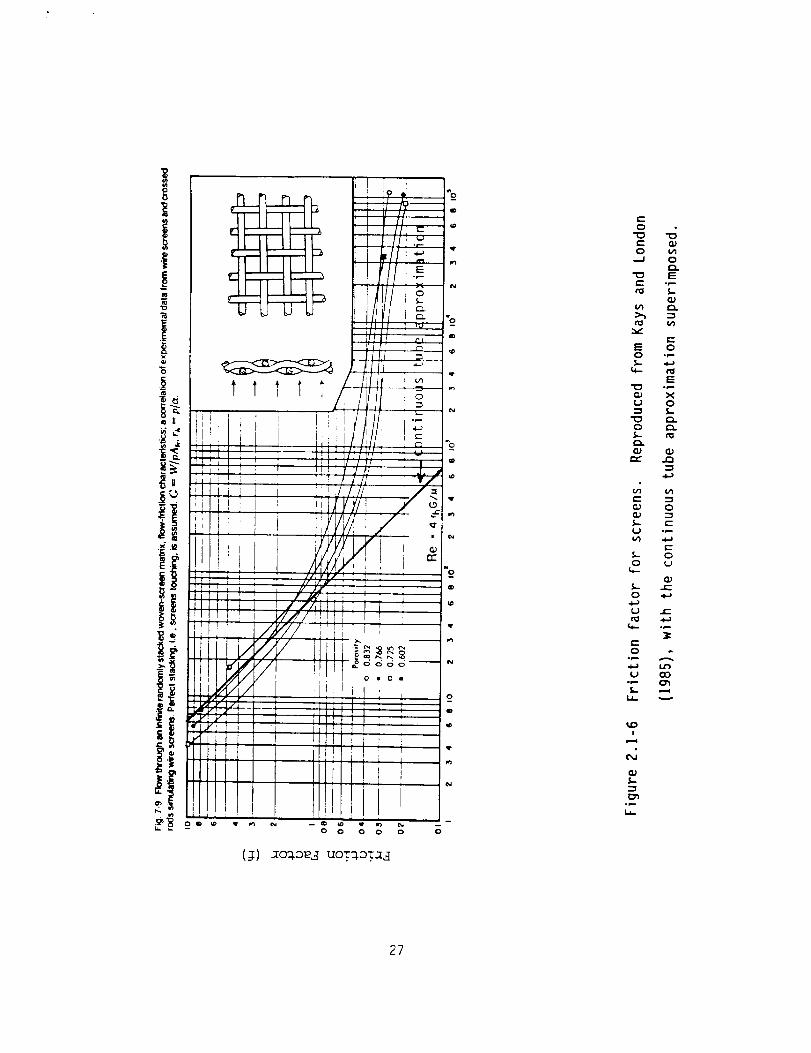
Figure 2.1-5 Calculation of pressure drop in graded screen regenerator.
25

Use or disctosure of data is subject to the restriction on the cover page of this report.
many continuous holes through that section of the regenerator, effectively
turning the screens into perforated plates. This approximation is acceptable
for Reynolds numbers less than about 100, and results in increasingly large
errors for higher Reynolds numbers, as shown in figure 2.1-6, which is
reproduced from page 149 of Kays and London. The computed values in figure
2.1-5 are approximately correct, since most of the pressure drop in the
regenerator occurs on the cold (low Reynolds no.) end.
The values in figure _.I-5 are for the most efficient graded screen
regenerator used in the experiments. The measured pressure drops are not as
large as those predicted in figure _.I-5.
The Electrical Analoq
In treating the effects of pressure drops on the pressure ratio, it is
important to note that the maximum pressure drop in the regenerator coincides
with the maximum local mass flow, while the maximum pressure coincides with
the zeroes in the local mass flow. This means that the pressure drops cannot
simply be used to correct the upper and lower pressures and recompute the
pressure ratio.
The electrical analog is useful in treating this case. The pressure is
associated with the voltage, the mass flow with the current, pressure drops
with resistance, and dead volumes with capacitance. In the electrical case we
have:
V = IR (2.1-9)
26
(1) xcr#ae3 uoT:_oTal
0
e-
0
co _a_3 o
-o E
E oO "_"
E
(D xu o
(D _J33
C
_J O
V) a._
O _J
_J
O
_J _-
rO
O°i--
4-_ 12)
L ,..,
_D!
_4_JL
_n
27

Use or disctosure of data is subject to the restriction on the cover page of this report,
dV ID
dt C
while for pressure and mass flow, we have:
(2.1-10)
AP = _ ( 128 fl L ) (2.1-11)
p Dh4 Nh
for the pressure drop across a screen or perforated plate with Nh holes of
hydraulic diameter Dh. For the isothermal addition of mass to a fixed volume
we have:
dP _ _ (R_T_T) (2.1-12)
dt moV
where mo is the molar weight. The result of significance here is that the
pressure swing AP and the pressure drop Pdrop are 90o out of phase and must be
added in quadrature. The total pressure swing at the entrance to the
regenerator (from which the pressure ratio is calculated) is given by
APentrance = [P2drop_regenerator + Ap2puls e tube ]I/2 (2.1-13)
The pressure ratio predicted using addition-in-quadrature for the pressure
swing in the pulse tube and the pressure drop across the regenerator is 1.82.
The measured value is between 1.47 and 1.64, depending on the average
pressure.
In summary, the simplified system model presented here provides rough
estimates of pressure ratio and mass flow. These estimates are accurate
enough to drive the generalized analysis model of the pulse tube, and the
regenerator model.
28

Use or disctosure of data is subject to the restriction on the cover page of this report.
2.2 Pulse Tube Model
In this section we will present a basic theory for the Orifice Pulse-Tube
cryocooler. Two previous approaches to this problem include:
a,
b.
The surface heat-pumping approach of Gifford and Longsworth.
The enthalpy-Zlow approach of Radebaugh, et al.
Our approach will use basic cycle thermodynamics as a starting point. We will
show that this approach reduces to the enthalpy-flow approach for optimized
cycle conditions. Our approach will not answer the question, "How does an
Orifice Pulse-Tube Cryocooler really work?".
interrelation of the thermodynamic variables,
importance to a cryocooler designer.
However, it will give the
and this is of primary
The testing program of Radebaugh at NIST has shown that the enthalpy-flow
model of the orifice pulse-tube cryocooler accounted for the observed
behavior. This was done in a test facility that was able to simulate ideal
regeneration and pressure wave generation. Therefore, the functional
relations in the enthalpy-flow model have been substantially confirmed. Thus,
since the generalized analysis approach gives similar relations, it too has
been confirmed. The surface heat-pumping approach appears to be more
applicable to the "basic" pulse-tube. That is, a pulse-tube without an
orifice and orifice volume.
29

Use or disctosure of data is subject to the restriction on the cover page of this report.
2.2.1 Generalized Analysis
Generalized analysis was originally developed by Rallis, but has been extended
by Walker. Both the original paper, Walker (1979) and the later version in
the book, Walker (1983), include many errors in the equations. We have gone
through this work, and corrected the errors, so that we can use the technique
to analyze cryocoolers. The analysis considers two basic types of compression
and expansion processes, isothermal and adiabatic. Two regeneration processes
are also considered, constant volume and constant pressure. We have found
that the constant pressure regeneration processes along with adiabatic
compression and expansion processes seem to be reasonable choices to model the
orifice pulse tube cryocooler. A short review of the generalized analysis
will be given, and then it will be applied to the pulse-tube cryocooler.
A schematic of a generalized cryocooler is given in Figure 2.2.1-I. P-V and
T-S diagrams for the generalized, adiabatic process with constant volume
regeneration is shown in Figure 2.2.1-2. This cycle corresponds to an
adiabatic Stirling machine. Definitions of the quantities used in the
analysis are given in Table 2.2.1-I. The equations for W/_, Q/_, and COP are
included in the figure. A corresponding figure for a generalized, adiabatic
process with constant pressure regeneration is shown in Figure 2.2.1-3. This
cycle corresponds to an adiabatic Ericsson machine.
The equations for Q in the figures can be compared to the equivalent equation
for Q developed by Radebaugh. Radebaugh used an enthalpy flow calculation to
derive the refrigeration power. This required the use of phasor analysis to
account for the phase shift induced by flow in the orifice. Generalized
3O

Use or disctosure of this data tm subject to the restriction on the cover page of this report.
0
C:
e-o
0e-.
I-
E0
r'-
e-
0
e-
X
.p-
.e-
e-
0_
'5
0
0
N
%f...
C.IC_
"7
t_
L.,_
31

Use or disctosure of this data is subject to the restriction on the cover page of this report.
p_¢l
L
t'-
I"¢ !
I
I t ,.ql I._
I ,--4 _ "" _" I?" _ l"" '--_S,. S- B ---.
"" II "-"
3
c
D _. q'
i/
/ /A,::,,Y.y/'- Sx
,-g
°_.-
o_...
o_
e-
I
o
C_
32

TABLE 2.2.1-I
Definition of Quantities for Generalized Analysis
r = volume expansion ratio
( = regenerator effectiveness
T = temperature ratio, Tc/T E
Tc = compression temperature
TE = expansion temperature
Q/<_> = specific cooling power at TE
W/<m> = specific work input at Tc
COP = coefficient of performance, Q/W
= ratio of specific heat, Cp/C v
33

Use or disclosure of this date is subject to the restriction on the cover page of this report.
L
t_
I i gi4 _ wil
_; ,--,I_. , I.. a o
I _ _ (_
I ' ' _-_ I_
°rB
:3C
mN
ID
N
I-
q.
w// i_
-_ t.,,.."_
Q.3
%
c-
O
"C
°_
.t-,-
F-
I
._
34

Use or disclosure of data is subject to the restriction on the cover page of this report.
analysis considers none of these detailed variables that are unique to the
pulse tube. This leads to the first assumption.
Assumption #I: Generalized analysis predicts the maximum value for COP, Q, W,
etc. based on the available volume compression and expansion ratios,
temperature ratio, regenerator effectiveness, and specific heat ratio of the
working fluid. If the "internal" variables are not optimized, the values can
be much less than the maximum values given by generalized analysis.
The equations given in Figures 2.2.1-I and 2.2.1-3 were developed on the
assumption that the volume compression ratio, rc, was the same as the volume
expansion ratio, re. We can then introduce a degradation factor, _D, into the
analysis in order to account for loss factors. Radebaugh carried out the same
basic process, and found that the actual refrigeration power (by experiment)
for the orifice pulse-tube cryocooler was I/3 the power predicted by the
enthalpy flow model. We can use the same factor in our analysis. Therefore
Qp -- I13 Qga (2.2.1-I)
Wp = I/3 Wga
I/3QgaCOPp -
Wp I/3 Wga
(2.2.1-2)
(2.2.1-3)
where the p subscript corresponds to predicted values and the ga subscript
corresponds to values obtained from generalized analysis.
35

Use or disclosure of data is subject to the restriction on the cover page of this report.
Assumption #2: The pulse tube refrigerator does not have a well-defined
volume expansion ratio like the typical cryocooler with a displacer or
expander piston. Therefore, we will account for this difference in cycle
operation by introducing a degradation factor, _D" This factor should be
constant with temperature, pressure ratio, etc. but might change for different
ratios of compressor volume to pulse tube volume.
Q
A series of charts have been developed to predict the COP and Q of the pulse
tube cryocooler as a function of expansion ratio and temperature. Five charts
(figs. 2.2.1-4 through 2.2.1-8) give COP vs. r at T : 2, 3, 4, 5 & 6. Five
charts (figs. 2.2.1-9 through 2.2.1-13) give Q vs. T at r = 1.2, 1.4, 1.6, 1.8
and 2. Effectiveness is a parameter in both sets of charts. The ten charts
for a series of "design" charts, and should allow us to predict the operation
of a pulse-tube cryocooler under a variety of circumstances.
2.2.2 Application of Generalized Analysis to Pulse Tubes
The expansion and compression processes in the orifice pulse-tube cryocooler
will be approximately adiabatic. The heat exchange and regeneration processes
will be carried out in low pressure drop systems, that have a fixed volume.
This means that the heat exchanger and regeneration processes are constant
pressure. Therefore, we assume that orifice pulse-tube cryocooler operates on
an Adiabatic Ericsson Generalized Cycle.
Some uses of the charts include:
a.) If we know the volume expansion ratio, r, we can determine the
specific refrigeration power Q/_. Then, if we know the mass and specific
36

Use or disc[osure of this data is subject to the restriction on the cover page of this report.
1.0
n00
0.8
0.6
-r=2
0.4 I "_I oOO, .... *...** _
, ".o..
I . • _,_ . ,_h'.''....o
,: I , ." ...... -:.:! : • • /
0.0 : I ,, , , , J
1.0 1.5 2.0
r"
Figure 2.2.1-4 Coefficient of Performance of an Orifice Pulse-Tube as aFunction of Expansion Ratio at _:2.
37

Use or disclosure of this data is subject to the restriction on the cover page of this report.
n00
0.5
0.4
0.3
0.2
0,1
/
I
I
I
"r=3 1.0=E- - .99..... .98-" - .97"- - .96.... .95
_ i5-----_-.......... _..._...........:...:...:...:...:
0.01.0 1.5 2.0 2.5 3.0
Figure 2.2.1-5 Coefficient of Performance of an Orifice Pulse Tube as aFunction of Expansion Ratio at T:3.
38

Use or disctosure of this data ts subject to the restriction on the cover page of this report.
15_00
0.3
0.2
0.1/
/
/0.0
1.0
Figure 2.2.1-6
1.0=c- -.99..... .98- - .97
- - .96.... .95
1.5 2.0 2.5 3.0
Coefficient of Performance of an Orifice Pulse-Tube as a
Function of Expansion Ratio at _=4.
39

Use or disctosure of this data is subject to the restriction on the cover page of this report,
0.25
I:1_00
0.20
0.15
0.10
0.05 /
/I
1.0=c- - .g9..... .g8-" - .97"- - .g6.... .g5
0.001.0 1.5 2.0 2.5 3.0
r
Figure 2.2.1-7 Coefficient of Performance of an Orifice Pulse-Tube asa Function of Expansion Ratio at _:5.
4O

Use or disclosure of this data is subject to the restriction on the cover page of this report.
0.20
15_00
0.15
0.10
0.05
/
-- 1.0=E_ _ .gg..... .98-" - .97"- - .96.... .95
0.001.0 1.5 2.0 2.5 3.0
r
Figure 2.2.1-8 Coefficient of Performance of an Orifice Pulse-Tube as
a Function of Expansion Ratio at T=6.
41

Use or disclosure of this data is subject to the restriction on the cover page of this report.
60
v
A
-EV
"0
5O
4O
3O
20
10
\
-- 1.0=e- - .99..... .98-" - .97"- - .96.... .95
r=l .2
I I I I I • •
1 2 3 4 5 6 7
./-
Figure 2.2.1-9 Specific cooling power as a function of temperature ratio
for an expansion ratio, r=i.2.
42

Use or disctosure of this data is subject to the restriction on the cover page of this report.
v
A
"Ev
.0
1O0
9O
80
70
60
5O
40
3O
20
10
0
1.0=_- - .99..... .98- - .97
- - .96.... .95
r=l .4
1 2 3 4 5 6 7
T
Figure 2.2.1-10 Specific cooling power as a function of temperature ratio
for an expansion ratio, r=I.4.
43

Use or disctosure of this data is subject to the restriction on the cover page of this report.
140
tm
v
-Ev
"0
120
100
80
6O
4O
20
0
-- 1.0=E- - .99..... .98-" - .97"- - .96.... .95
r=1.6
I 2 3
I"
Figure 2.2.1-11 Specific cooling power as a function of temperature ratio
for an expansion ratio, r=].6.
44

Use or disctosure of this data is subject to the restriction on the cover page of this report.
180
160
140
.-_ 120
100
.E 80
•o 60
40
2O
I . • • • I" _. .'_ _ IQ_" ....
1 2 3 4- 5 6 7
-- 1.0=E r= 1- - .99..... .98-- - .97
"_& - - -.96
...."._'''
• _ • "o.•"._' _ "'... _
• % _ "'*..,..,o.,
I"
Figure 2.2.1-12 Specific cooling power as a function of temperature ratio
for an expansion ratio, r=I.8.
45

Use or disctosure of this datl is subject to the restriction on the cover page of this report.
200
v
A
-Ev
.Or
180
1 60
140
120
100
8O
60
40
2O
0
1.0=E- - .99..... .98-. - .97- - -.96.... .95
r=2.0
I
1 2 7
°°,,.
_ "q_'* ''''''...."'''*°'°...,
• i • • I , ", , . _1 • _ _i, -ill °''"" _''11
3 4 5 6
1"
Figure 2.2.1-13 Specific cooling power as a function of temperature ratiofor an expansion ratio, r:2.0.
46

Use or disclosure of data is subject to the restriction on the cover page of this report.
heat of the cold section of the cryocooler, we can determine the
effective mass flow into the pulse-tube by measuring the initial cooldown
rate of the system. If we have an independent way of measuring the mass
flow, this can be used as a check of the process.
b.) If we operate the cryocooler with no heat load (the parasitics must
be accounted for)'and measure the minimum temperature reached, we can
determine the regenerator effectiveness if the volume expansion ratio, r,
is known.
c.) If a cryocooler is operated at a fixed expansion ratio, r, but with
variable heat input the cryocooler temperature will raise with heat
input. The locus of points will lie along a constant effectiveness, E,
line.
2.3 Reqenerator Model
This section contains a theoretical development of the design of perforated
plate regenerators.
The regenerator design equations must provide a link between the design
requirements and materials and fluid properties and the regenerator design
parameters over which we have control.
The design parameters are:
a. the diameter of the holes in the perforated plates,
b. the diameter of the plates themselves,
47

Use or disctosure of data is subject to the restriction on the cover page of this report.
C.
d.
the number of holes in each plate,
the total length of the regenerator.
The design requirements include:
a.
b.
C.
d.
the working mass flow,
the allowable pressure drop,
the properties of the working fluid,
the required efficiency.
Regenerator inefficiency may be attributed to two separate effects. The first
is the finite temperature difference required to drive the wall-fluid heat
transfer, while the second is the finite periodic temperature swing in the
matrix caused by the fact that the matrix does not have infinite thermal mass.
These inefficiencies contribute to the difference between the actual exit
stream temperature and the optimal exit stream temperature (TL). At the end
of the compression (hot blow) stroke, the matrix will have been heated above
the lower temperature extreme (TL). On top of this temperature difference,
there will be the wall-fluid temperature difference required to drive the
wall-fluid heat exchange. The net temperature difference represents excess
heat that is carried into the cold end of the pulse tube, reducing the total
cooling power.
In a periodic flow counterflow regenerator with zero dead volume and a high
number of NTUs, the temperature distribution along the length of the
regenerator can be quite non-linear, as shown in Figure 2.3-I. However, in
the regenerators used with a pulse tube, the dead volume can be a significant
fraction of the volume of the pulse tube and we may visualize at least part of
48

L.
(3J..
CL
E
Tu
TI
At Start of
..____-- Hot Blow
\
At End of
Hot Blow
\
\
0
Distance Along Regenerator
Figure 2.3-I Temperature distribution along zero dead volume regenerator
49

Use or disclosure of data is subject to the restriction on the cover page of this report.
the gas as a "plug" that moves into and out of the regenerator, rather than
strictly through it. This effect will tend to flatten and linearize the
temperature distribution.
We have used the linear temperature distribution shown in Figure 2.3-2. This
distribution has the advantage of mathematical simplicity, and is easily seen
to be a conservative approximation. It is also quite likely to be a fairly
accurate description of the regenerators with finite dead volume. This linear
approximation entails (roughly) the following set of implicit assumptions:
a°
b.
C.
d.
the capacity of the matrix does not vary along the regenerator,
the wall-fluid resistance does not vary along the regenerator,
the heat transfer is uniform along the regenerator,
the specific heat of the gas is uniform along the regenerator.
All of the variables and symbols used in the following discussion are defined
in Figure 2.3-3.
The quantity of interest is the excess heat carried into the cold end of the
pulse tube, and can be written in the form:
Aq = Cpf(T(t) - TL) _(t)dt
J blowst roke
(2.3-I)
The temperature of the gas emerging from the lower end of the regenerator is a
periodic function.
5O

L,.
_3
(3-
E
I--
Tu
TI
Af End of
_. -.. _ -. ,_ Hot Blow
Hot Blow
0
Distance Along Regenerator
Figure 2.3-2 Linearized temperature distribution along finite dead volume
regenerator
51

TL =
Tu =
T(t) -
Aq =
Cp =mma X =
_(t) -<_>
AT(t) =
ATma x =
ATwf =
ATm
ATe
h w =
Aw =
T =
Vm =
Cm =
(l-_)e =
(l-()w f =
(1-()m =6 =
# =
L =
p =
Dh =
Nh =
Dp =<Ap> =
APma x =NU =
k =
DV =
Minimum temperature of lower end of regenerator
Temperature at upper end of regenerator
Temperature at lower end of regenerator as a function of
time
Excess heat emerging from lower end of regenerator
Specific heat at constant pressure
Maximum mass flow
Mass flow as a function of time (roughly sinusoidal)
Average mass flow
T(t) TL
Maximum value of AT(t)
Maximum value of the wall-fluid temperature difference
at the lowerend of the regenerator
Maximum value of the matrix temperature difference
at the lower end of the regenerator
Average effective total temperature difference at the
lower end of regenerator
Surface heat transfer coefficient
Wall area of the regenerator
Period of sinusoidal pressure variation
Volume of the regenerator matrix
Volumetric heat capacity of matrix
Average effective ineffectiveness of regenerator
Ineffectiveness due to wall-fluid interaction
Ineffectiveness due to finite matrix capacity
Ratio of (1-()m to (1-()wf
Fluid viscosity
Length of regenerator
Fluid density
Diameter of holes in regenerator plate
Number of holes in regenerator plate
Diameter of regenerator plate
Time-average pressure deop across regenerator
Maximum pressure drop across regenerator
Nusselt number
Fluid thermal conductivity
Porosity of regenerator plate
Dead volume of regenerator
Figure 2.3-3 Definitions of Variables and Symbols Used in Generator Analysis
52

Use or disclosure of data is subject to the restriction on the cover ;)age of this report.
We have used the (again conservative) assumption that the gas temperature at
the lower end of the regenerator is equal to TL only at the end of the cold
blow (expansion) stroke, as shown in Figure 2.3-4. We may write the mass
flow at the cold end of the regenerator as:
@(t) = mmax sin(wt) (2.3-2)
Noting that the wall-fluid temperature difference is in phase with the mass
flow while the matrix term lags by 90 degrees, we can write the temperature at
the cold end of the regenerator as:
T(t) = (TL + ATmax) + ATma x sin(wt + 6)
= TL + (ATwf + ATm)
+ aTwf sin(wt) + 6Tm(-COS(Wt))
(2.3-3)
where ATwf and ATm are given by:
mma x Cp (Tu-TL)aTwf = (2.3-4)
hwA w
(T/4) <_> Cp (Tu-TL)ATm = (2.3-5)
VmC m
where <_> is the time-average mass flow.
The heat transferred into the cold end of the pulse tube is then given by:
jAq = Cp / AT(t) _(tldt - Cp (T(t) - TL) m(t)dt (2.3-6)blowstroke blowstrokeJ
53

Q)L.
O
C)_
E
TL+2ATmox
TL+ ATmax
T L
/ .o_ cold \
Tavg.
aTmax
Time
Figure 2.3-4 Gas temperature at cold end of regenerator
54

Use or disctosure of data is subject to the restriction on the cover page of this report.
FrL j blowstroke 7
+ f ATm (1-cos(wt)) " sin (wt) dt[Jbl owstroke mmax ]
(2.3-7)
Examining equation (2.3-7), we are encouraged to define an average effective
temperature difference in the form:
AT e - [AT2wf + AT2m]I/2 (2.3-8)
The efficiency can then be expressed by:
(1-() e : 2ATe/(Tu-T L) (2.3-9)
where the origin of the factor of two in the numerator is clear from Figure
2.3-4. The inefficiency can be written explicitly in terms of the two
contributing terms as:
(]-()e : [(1-e)2wf + (1-e)2m]I/2 (2.3-10)
The inefficiencies due to wall-fluid term and matrix term can be further
parameterized by their ratio, which gives:
6 -- (1-()m/(1-e)w f (2.3-11)
and
(I-() e
(1-()wf - [i+6211/2 (2.3-12)
_(I-()e
(1-E)m: [1+ 62]I/2 (2.3-13)
55

Use or disctosure of data is subject to the restriction on the cover page of this report.
We are now prepared to develop the design equations for the regenerator. In
all cases, the average mass flow <m> is used. The average mass flow is given
by:
<_> --
_(t) dtlowstroke
/Itblowstroke
(2.3-14)
and is related to the peak mass flow through:
<&> 2= - mmax (2.3-15)
This peak mass flow occurs twice per cycle, once during the compression
stroke, and once during the expansion stroke. Since the entrance and return
lines for the pulse tube are the same line, the average mass flow for
refrigeration purposes is half the average mass flow during the compression
stroke.
The average pressure drop is given by:
128 # <_> L
<AP> = (2.3-16)
_p D4h Nh
and is related to the peak pressure drop by:
2<AP> = - @max (2.3-17)
56

Use or disctosure of data is subject to the restriction on the cover page of this report.
As indicated in equation (4), ATwf is given by:
mmax Cp (Tu TL)
hwAw
_<_>cp(T u - TL)
2hwA w
(2.3-18)
where (hw) is defined in terms of the Nusselt number, fluid, and geometry:
hw : Nu k/D h (2.3-19)
and ATm is given by:
(T/4) <m> Cp (Tu - TL)ATm : (2.3-20)
VmC m
The porosity (o) is defined by:
NhD2h= (2.3-217
Dp 2
and the total heat exchange area is given by:
Aw = _DhNhL
and the matrix volume is given by:
(2.3-22)
D2p L(1-o)Vm = (2.3-23)
4
Inserting (2.3-197, (2.3-227, and (2.3-97 into (2.3-187, we can eliminate
(hw), (Aw), and (Tu - TL7 in favor of Nu (the Nusselt number, the actual wall
area, and the "wall ineffectiveness" ((1-()wf) respectively, giving :
<m> Cp = Nu k Nh L (1-()wf (2.3-24)
57

Use or disclosure of data is subject to the restriction on the cover page of this report.
Similarly, substituting (2.3-23) and (2.3-12) into (2.3-20) we can eliminate
Vm and (T u TL) in favor of the actual matrix volume and the "matrix
effectiveness" ((1-()m), giving"
2r<_>Cp : _(l-e) D2p L Cm (l-e)m (2.3-25)
Using (2.3-12) and (2.3-13) to express (2.3-24) and (2.3-25) in terms of the
overall effectiveness (1-epsilon) e, we have:
[I + 62] I/2 <m> Cp : Nu k Nh L (I-() e
and:
(2.3-26)
[1 + 6211/2
62 T <m> Cp : _(1-e)D2p L Cm (I-c) e (2.3-27)
Now, rewriting (2.3-16), (2.3-21), (2.3-26), and (2.3-27) to put all the
design parameters on the left and all the materials properties and design
requirements on the right, we have"
128 # <_>
D4h Nh/L - (2.3-28)_p <AP>
[I + 62] I/2 <m> Cp
NhL = (2.3-29)
Nu k (]-()e
211 + 62] I/2 T <_> Cp
D2p L = (2.3-30)_6(1--a)Cm(1-E) e
D2p
NhD2h
= (I/e) (2.3-31)
58

Use or disctosure of data is subject to the restricti¢_ on the cover page of this report.
Identifying the right hand sides of each equation as a design constant,have:
128 # <6>A-
_p <AP>(2.3-32)
we
B E
C ---
[I+62] I/2 <6> Cp
Nu k (]-()e
211+6211/2T<_>Cp
_6(]--a) Cm (l-()e
(2.3-33)
(2.3-34)
Solution of this set of equations for Dh, Nh, L, Dp, and the dead volume (DV)yields:
Dh = [_C/B] I/2 (2.3-35)
[AB3]I/2
Nh - (2.3-36)(_C
L
_C
[AB]I/2(2.3-37)
[AB]I/4
Dp - ei/2 (2.3-38)
DV = _ec/4 (2.3-39)
Finally, re-expanding the constants into matsrials properties and design
requirements gives:
2 e T Nu k ] I/2Dh= _6_l___-_m(2.3-40)
59

Use or disclosure of data is subject to the restriction on the cover page of this report.
Nh = 46F 2x[1+62] I/2 # Cp )elCml Lp k3 (TT_(
-8 ]-e
Dp = 4 (<m__.>>)I/2(_
I/2
i I i/2
211+62] I/2 # <AP> Nu k Cp
/_ (l-e) e
•-, 1/4
' [i+6211/2 ]
# Cp
2_p <AP> Nu k (1-E)e
i/2
(2.3-41)
(2.3-42)
(2.3-43)
(2.3-44)
The above are the design equations for perforated plate regenerators. They
express the design parameters in terms of materials properties, known
quantities, and design requirements. The single unspecified quantity
appearing on the right of the design equations is (6), the ratio of matrix
ineffectiveness to wall-fluid ineffectiveness. This ratio may be thought of
as an optimization parameter. For each value of (6), there will be a single
design meeting the design requirements. The range of designs generated by
varying (6) form an optimization space. For example, if the design is
required to optimize regenerator weight for a given (fixed) efficiency,
varying delta will generate a range of regenerator designs from one with
excellent wall-fluid efficiency and low matrix mass (small 6) to one with
relatively poorer wall fluid efficiency and large matrix mass (large 6). The
minimum weight will be obtained for a given value of delta, representing the
(weight) optimum regenerator.
6O

Use or disclosure of data is subject to the restrictioq_ on the cover page of this report.
2.4 Experimental Studies and Results
This section describes the experimental studies conducted in this program, and
the results of those experiments. The early studies are discussed briefly,
but the bulk of this section is devoted to the most recent experimental
results leading to the current "best-effort" prototype design (Sec. 3).
Attention is also given to the successful use of the new design and analysis
tools in the final stages of this program, including pulse tube and
regenerator optimization.
2.4.1 The Regenerator Test Facility
The regenerator test facility is shown in figure 2.4.1-I. This facility was
designed to provide performance testing and verification for the periodic
counterflow regenerators used in a pulse tube refrigerator. The regenerators
are tested under realistic flow and temperature conditions. At room
temperature, the facility consists of a gas handling system, a pressure wave
generator (compressor), and a heat exchanger for the pressure wave generator.
Within the cryostat, the facility has an isothermalizer (to insure that input
gas remains at 30OK), a liquid nitrogen pot and heat exchanger, connections
for the regenerator under test, and pressure and temperature sensors for the
inlet (hot) and outlet (cold) end of the regenerator.
The pressure sensors located on the inlet and outlet of the regenerator are
are Siemens KPY-14 sensors with a linear operating range of 0-I+ MPa. The
sensor bridge is excited by a DC voltage, and the output signal is measured by
a high impedance digital multimeter (Dynascan model 2831). The DC component
61

_Pump Out Line
_Feed Thru ,
LN 2 BBoth I. - r----'l !
_HX'
Vocuum
Spoce
"/ Regenerator,\
Meter
i i:
Compressor
jSupply
-- lsoihermolizer
--LN _. JocKel
Figure 2.4.]-IThe Regenerator Test Facility
62

Use or disctosure of deta is subject to the restriction on the cover page of this report.
gives the average absolute pressure in the system, and the AC component gives
the pressure swing.
Temperature measurement and control are provided by a Lake Shore Cryotronics
Model DRC-gIc Temperature Controller, and three model DT-470-SD-12 silicon
diode sensors. One of these sensors was calibrated by Lake Shore Cryotronics
prior to delivery, and we transferred this calibration to the other two
sensors. Temperature sensors are located at the inlet and outlet of the
regenerator and on the isothermalizer, for which temperature control is
provided.
In operation, the system is allowed to come to equilibrium with working
pressure in the regenerator, but no periodic pressure swing. This establishes
the "baseline" heating delivered to the liquid nitrogen pot. The heating is
determined by measuring the boiloff of liquid nitrogen using the flow meter
installed in the exit line to the pot. Once the baseline heat load has been
determined, the regenerator is driven by a periodic pressure swing generated
by the pressure wave generator. Gas moves periodically into and out of the
heat exchanger in the liquid nitrogen bath through the regenerator under test.
If the regenerator is perfectly efficient, the gas pushed through the
regenerator on each compression stroke deposits its heat in the regenerator
and is cooled to liquid nitrogen temperature, and reabsorbs this heat as it
emerges through the regenerator on the expansion stroke. If the regenerator
is not perfectly efficient, there will be a temperature difference between the
cold end of the regenerator and the emerging gas, and some heat will be
carried into the heat exchanger in the nitrogen pot, resulting in additional
boiloff.
63

Use or disctosure of data is subject to the restriction on the cover page of this report.
Following an initial transient behavior after the pressure wave generator is
turned on, the system will again reach equilibrium. The increased boiloff
provides a measure of the heat transferred into the heat exchanger as a result
of regenerator inefficiency.
The expression for regenerator inefficiency (I-() is:
(I-() : AH / mHe Cp AT (2.4.1-I)
where:
AT = Tuppe r Tlowe r = 300 K 77 K (2.4.1-2)
and:
AH : (mLN2 _LN2') QL (2.4.1-3)
where mLN2' is the mass flow rate of the LN2 boiloff before the pressure wave
generator is turned on, mLN2 is the mass flow rate after the pressure wave
generator is turned on, mHe is the mass flow rate of the helium gas in the
regenerator, and QL is the latent heat of vaporization.
2.4.2 Pulse Tube Test Facility
The final arrangement for the pulse tube test facility is shown in figure
2.4.2-I. A G.A.S.T. 1HAB-19 compressor was modified to provide a variable
volume pressure wave generator, encapsulated in a pressure vessel to remove
64

0(/)
Lr_ r_
V_
q_I'
\
°--
c_.4B
c_
°__ >
G>i
1 -Q_O.
_Q
F--
(I)
C1_
I
0(1)
c_
Q.
0
,ii
P
//"
0
C_
q_
0IB
°_
"5r_
C_
..0
I--
7'
c_
C_°r-I..i-
65

Use or disclosure of data is subject to the restriction on the cover page of this report.
the forces associated with the average pressure in the system, and mounted in
the immediate vicinity of the top plate of the cryostat. The modifications to
the compressor are shown in figure 2.4.2-2 and figure 2.4.2-3.
The compressor is driven by a variable DC power supply, from which the driving
voltage and current can be measured, allowing us to compute the total
electrical input power 5o the pulse tube refrigerator.
Pressure sensors are located on the downstream end of the connecting line
immediately above the entrance into the cryostat, and on the connecting line
between the hot end of the pulse tube and the orifice volume, downstream of
the orifice valve.
The pressure sensor located on the connecting line is a Siemens KPY-]4. The
sensor bridge is excited by a DC voltage, and the output signal is measured by
a digital multimeter. The DC component gives the average absolute pressure in
the system, and the AC component gives the pressure swing at the downstream
end of the connecting line.
The pressure sensor located between the orifice valve and the orifice volume
is a SETRA model 205-2. This sensor is calibrated to provide accurate
pressure measurements from 0 to 3.4 MPa The DC component again provides the
average absolute pressure, and the AC component provides the pressure swing.
To measure the pressure ratio in the hot end of the pulse tube, the valve
between the pressure sensor and the orifice volume is fully closed, and the
orifice valve is opened completely. The pressure swing (AC component) is
measured with both a digital multimeter, and an oscilloscope. The RMS value
66
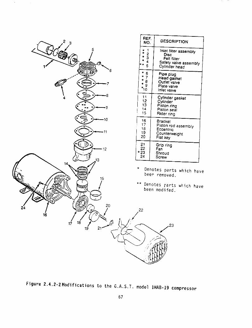
REF. DESCRIPTION
2 3 NO.
* 4 Safety valve assembly** 5 Cylinder head
6 * 6 Pipe plug* 7 Head gasket
-."" * 8 Outlet valve
"10 Inlet valve
11 Cylinder gasket12 Cylinder
13 Piston ring
.-,---- 9 14 Piston seal15 Rider ring
10 16 Bracket17 Piston rod assembly
Figure 2.4.2-2 Modifications to the G.A.S.T. model IHAB-Ig compressor
67

ompressor
Ultra
", \
i
L
'\\
'\
'1!
1_---i
i:
F! K_-
L _iI _; ./'
Torr Fittings
'\,, "\\
\\
!_,_ ,,," ' '\\ [L
\
//
/
//
/
__j.j"/'
//
PressureTonk
Figure 2.4.2-3Encapsulation of modified compressor
68

Use or disctosure of data is subject to the restriction on the cover page of this report.
provided by the DMM agrees well with the measurements made using the
oscilloscope, and the waveform is approximately sinusoidal.
In all cases, the pressure ratio is computed by assuming that the pressure
swing is symmetrical about the average pressure. The peak swing is added to
the average pressure to obtain Pmax, the peak swing is subtracted from the
average pressure to obtain Pmin, and the pressure ratio is given by:
Rp : Pmax / Pmin (2.4.2-I)
In the interest of obtaining a better picture of the distribution of pressure
drops and mass flows in the pulse tube system, several attempts were made to
install a KPY-14 pressure sensor on the connecting line between the cold end
of the regenerator and the cold end of the pulse tube. These attempts were
unsuccessful. Because of its sensitivity to heat, the KYP sensor could not be
hard soldered into the line, and neither soft solder nor epoxy proved reliable
for use at low temperatures with 10 Atm. average pressure and 1.5 Atm.
periodic pressure swings.
The SETRA gage also provided a crude means of measuring the mass flow into and
out of the hot end of the pulse tube during run. The AC signal from the SETRA
gage with the orifice valve in the running position, and the orifice volume
connected was near the lower limit of resolution, but could be measured
approximately to give an estimate (within -30%) of the mass flow between the
hot end of the pulse tube and the orifice volume.
69

Use or disctosure of data is subject to the restriction on the cover page of this report.
Temperature measurement and control are provided by a Lake Shore Cryotronics
Model DRC-9]C Temperature Controller, and three model DT-470-SD-12 silicon
diode sensors.
One of the temperature sensors is installed at the top plate of the cryostat
to monitor the temperature of the gas delivered by the pressure wave
generator, while the other two are installed at the cold ends of the
regenerator and pulse tube respectively.
To provide information on the thermal distribution along the regenerator the
temperature sensor from the cold end of the pulse tube was moved to the
geometric center of the regenerator on at least one occasion,.
A heater is provided at the lower end of the regenerator (consistent with
Radebaugh's placement). This heater consists of 28 cm of 40 gauge (3 mil)
Manganin wire, with a total resistance of 25 Ohms. The heater is wound in
intimate thermal contact with the lower (cold) end of the regenerator, is
driven by a Lambda LA-200 power supply, and the input voltage is measured
using a digital multimeter. The applied heat load was taken to be:
= V2 / R (2.4.2-2)
No attempt was made to use a 4-wire arrangement for the heater, since the
copper leads to the heater dissipate a negligible fraction ( < I% ) of the
applied power.
7O

Use or disclosure of data is subject to the restriction on the cover page of this report.
2.4.3 Early Studies
The regenerator test facility was used to measure the performance of several
early regenerator designs, two of those are discussed here. The regenerators
were:
a. a perforated plate regenerator 0.30 cm in diameter, 7.5 cm in length, and
containing 233 perforated copper plates with 340 34x]00 micron holes,
b+ a screen regenerator 0.63 cm in diameter, 7.5cm in length containing 1100
discs of 400 mesh stainless steel wire cloth.
The regenerators were tested using the facility and techniques described in
section 2.4.1 above. The results were:
a. the perforated plate regenerator had an efficiency of 99.3% with a mass
flow of 0.023 g/s, and a measured pressure drop of 0.146 MPa,
b. the screen regenerator had an efficiency of 99.4% with a mass flow of
0.031 g/s, and a measured pressure drop of 0.088 MPa.
These results demonstrated that the perforated plate regenerator had higher
efficiency than a screen regenerator with the same envelop. However, the mass
flows required for an 80K 0.25W pulse tube refrigerator were projected to be
sufficiently high that the required efficiency could not be obtained using the
(then) available small diameter (0.27 cm) perforated plate material.
7!

Use or disctosure of data is subject to the restriction on the cover page of this report.
Regenerator design continued with both screen and larger diameter perforated
plate material as it became available. In many cases, the use of screens
allowed significantly more design freedom, especially since production model
regenerators would still be implemented in perforated plate material with one
or a mixture of the following advantages:
a°
b.
better efficiency and lower dead volume in the same envelop
equal efficiency and lower dead volume in a smaller envelop
Because of the sometimes unexpected interactions of the various components of
the pulse tube refrigerator, separate regenerator testing was gradually
abandoned in favor of system testing on the Pulse Tube Test Facility.
A number of tests of complete pulse tube refrigerators were performed using
the Pulse Tube Test Facility and the 290cc pressure wave generator. The best
performance was achieved using a regenerator 2.54 cm in diameter, 7.0 cm in
length, and containing 700 discs of 400 mesh stainless steel wire cloth, and a
pulse tube 1.27 cm in diameter, 24 cm in length with 80 mesh copper screen
heat exchangers. This combination reached an ultimate temperature of I02K.
The early tests indicated that the original models of pulse tube and
regenerator performance were inadequate to the task of establishing an
a-priori design that would meet the program requirements. Much of this early
work was devoted to exploring the interaction of the compressor, regenerator,
and pulse tube, and developing a qualitative understanding of system
performance.
72

Use or disctosure of data is subject to the restriction on the cover page of this report.
Based on these early experiments and that qualitative understanding, the
generalized analysis approach to pulse tube performance (Sec 2.2) gradually
evolved, along with a simplified approach to modeling regenerators (Sec 2.3).
At the same time, it became clear that the 290cc compressor was not a good
match to the volumes of the pulse tube refrigerators of interest in this
program, and the decision was made to augment the test facility with a much
smaller pressure wave generator.
2.4.4 Studies with the 20cc Pressure Pressure Wave Generator
Once it became clear that a better volume match between the compressor and the
pulse tube system was required to make experimental progress, we installed the
modified G.A.S.T compressor (discussed in section 2.4.2). Rapid progress was
made using this compressor, and a temperature of 116 K was reached using a
perforated plate regenerator 0.95 cm in outside diameter, 11 cm in length,
containing 120 F-61 perforated plates of graded length (as described below)
and a pulse tube 0.95 cm in outside diameter, 12 cm in length, with F-61
perforated plug heat exchangers, as described in figure 2.4.4-3. The F-61
material is 0.89 cm (0.350 inch) diameter with 3781 holes 95 microns in
diameter.
Pulse Tube Optimization. At this point, we elected to optimize the pulse tube
to the regenerator. To determine the effects of pulse tube volume (and
consequently Rp and the mass flow), this regenerator was used with a selection
of six different pulse tubes, described in figure 2.4.4-I. As expected, the
ultimate temperature reached by these pulse tube / regenerator combinations
depended on the pressure ratio Rp and mass flow in the pulse tube. The
73

X
-r
c
(_)
v
ED
_=
E_
O
O
C
C_
E_
uJ u_ u_ ] or) U_I UC C C C C C
_' _ --
g g_ U'J
10-_ o.._ i o.._, E
:010 c>
L_ Lr-
,,_,..7 CCI C
1C',I O,,I! O,
_!_o o_c
1
0 0 U_ U") U") _la_ U7
o 0 o 0 o'o c.:iI
I0 0 0,0 010 _,'
o oo o c:io o'
o of!O o o o ._
mc_ _Oh OhC_
-- o o o O!o o
0 0 LI"):Lf") U") U-) U70 LIT I"-- P',- P'-- I".- r',-
oodoooo
"_ e..h,tD tm wll_ c__
74
c-o
N°_m
E°r--,
o
°_m
4.+')
o
o
"E
°_...
¢-.
'T
d
°r-

Use or disctosure of data is subject to the restriction on the cover page of this report.
summary results are shown in figure 2.4.4-2. The ultimate temperature is
reduced as the pulse tube volume is decreased because the regenerator operates
more efficiently with lower mass flow. This trend continues as the mass flow
is further reduced, until the remaining mass flow is insufficient to support
the heat leaks into the cold end through the regenerator and the walls of the
pulse tube.
This study indicated that the 11cm pulse tubes were near the optimum for the
perforated plate regenerator, and that whether the heat exchangers were made
of F-61 plugs or 80 mesh copper screen had little effect on the ultimate
temperature. The ultimate temperature for the plate regenerator and the 12cm
pulse tubes was between 116 and 118K, at a pressure ratio of 1.44.
Regenerator Optimization. Using the 0.95 cm diameter by 12 cm pulse tube with
screen heat exchangers (PT-G), we embarked on a program of regenerator
optimization. To reduce the lead time associated with acquisition of the
perforated plates, and to retain design flexibility, we elected to develop a
series of screen regenerators, beginning with one that closely approximated
the perforated plate design.
The hole size in the F-61 plates is 95 micron, closely matching the edge
dimension (- 103 micron) of the holes in 150-mesh stainless screen. However,
based on the graphs in Kays and London (1985), the screens are expected to
have a higher friction factor than the perforated plates for the same number
of comparable holes and the same overall length. In an effort to maintain or
improve the wall-to-fluid thermal contact at the cold end and not introduce an
intolerable pressure drop across the regenerator, we selected a graded design
75

1.6 160
0
III=I
f_I6
1.5"
1.4
1.3
__ Rp
T (ultimate)
\
2I I i
6 6
Pulse Tube Volume (cc)
I0
150
140
130
120
110
A
6.
I6IQ,
Em
m
ID
E
O
ID
r
0.6
0.5
0.4
0.3
0.2
2
__ mdot
T (ultimate) .,_/J/
//*
'\ .//
\ <
S j" "\ _j---_
!b0A
150 mL
0
140 _"I)
E
130 I-
©
120 E
, , , 110
4 6 8 10
Pulse Tube Volume (cc)
Figure 2.4.4-2Results of pulse tube optimization. The upper graph shows the
pressure ratio and ultimate temperature as a function of pulse
tube volume, while the lower graph shows mass flow and ultimate
temperature as a function of pulse tube volume.
76

Use or disctosure of data is subject to the restriction on the cover page of this report.
(regenerator 0 in figure 2.4.4-3) with a diameter of 1.27 cm, and a total
active length of 12cm containing approximately equal lengths (4cm each) of
lO0-mesh (160 discs), 150-mesh (200 discs), and 200-mesh (250 discs). This
regenerator was operated with PT-G the reached a temperature of 87.1K, at a
pressure ratio of 1.28, indicating much improved regenerator efficiency, and
somewhat lower mass flow.
Encouraged by the agreement between predicted and measured performance of this
pulse tube / regenerator combination, we elected to build a second graded
regenerator (R-J) with a diameter of 1.g]cm (3/4 inch), a length of 6cm,
again equally divided between 100-, 150-, and 200-mesh stainless steel
screens. This regenerator was expected to provide performance comparable to
R-O with lower pressure drop. The performance was significantly worse, with
an ultimate temperature of 128.6K at a pressure ratio of 1.28. The degraded
performance was attributed to the formation of "jets" at the entrance and exit
of the regenerator where I/4 inch and I/8 inch OD connecting lines join. It
was also noted, however, that the pressure ratio was unchanged, indicating
that the pressure drop in R-O was insignificant.
Based on the fact that the pressure drop in R-O was not the limiting factor in
the system performance, we designed another graded regenerator (R-X) with a
diameter of 1.27 cm, and a total active length of 12cm containing
approximately equal lengths (3cm each) of lO0-mesh (100 discs), 150-mesh (152
discs), 200-mesh (188 discs) and 250-mesh (246 discs). This design was
expected to provide significantly higher efficiency with a corresponding
increase in pressure drop across the regenerator (as shown in figure 2.4.4-4).
77

100 x 100 mesh
150 x 150 mesh
200 x 700 mesh
250 x 250 mesh
100 x 100 mesh
150 x 150 mesh
200 x 200 mesh
250 x 250 mesh
325 x 325 mesh
400 x 400 mesh
Screen Regenerators
12 cm long
100 × _OC, mesh
•"------- 150 x 150 mesh
200 x 200 mesh
.010 plates - 40i
.017 plates - 40
.035 plates - 40
Plate Reaenerators
1 1 cm long
Figure 2.4.4-3Designs for four graded regenerators. Regenerator-X is at
upper left. Regenerator-Y is in upper middle. Regenerator-O
is at upper right, and regenerator-H is in lower middle.
78

300000
e_w 200000
0b
ob
o
100000
-o- Pdrop (avg)-_- Pdrop (peak)
/
//
/"
/i.
../
_4D_°
// i
i i I
Regen-O Regen-X Regen-V
Figure 2.4.4-4Predicted pressure drops for regenerators O, X, and Y.
79

Use or di$ctosure of data is subject to the restriction on the cover page of this report.
This design was tested with PT-G and the ultimate temperature reached was
77.gK with liquid nitrogen in the jacket of the cryostat (to reduce radiative
load) and a gas supply temperature of 30OK, maintained by cold nitrogen flow
in the heat exchanger on the connecting line. Without liquid nitrogen in the
cryostat jacket and using water in the heat exchanger on the connecting line,
the inlet temperature was 304K, and the ultimate temperature was 82.8K, at a
pressure ratio of 1.28.
Noting again that the pressure ratio had not declined, indicating that the
total pressure drop across the regenerator was not yet the limiting factor in
system performance, we designed a final graded regenerator (R-Y) with six
graded screen sections. R-Y has a diameter of 1.27 cm, and a total active
length of 12cm containing approximately equal lengths (2cm each) of 100-mesh
(60 discs), 150-mesh (104 discs), 200-mesh (128 discs), 250-mesh (164 discs),
325-mesh (188 discs) and 400-mesh (240 discs). The predicted pressure drop
for this regenerator is approximately twice that for R-X, as shown in figure
2.4.4-4.
This regenerator was tested with PT-G, and an ultimate temperature of 77K was
reached with water in the heat exchanger on the connecting line and no liquid
nitrogen in the cryostat jacket. The pressure ratio was between 1.22 and
1.25, indicating that the pressure drop in the regenerator was becoming
significant in the computation of pressure and mass flow distributions.
This pulse tube / regenerator combination is the current baseline, and its
physical characteristics and performance are described in detail below.
BO

Use or disctosure of data is subject to the restriction on the cover page of this report.
3.0 CURRENT PROTOTYPE
This section describes the current prototype in detail, along with analytical
predictions and measured performance. Bear in mind, that although the current
prototype almost meets the requirements of a 0.25 Watt 80K cryocooler, it is
not considered a finished item. Specifically, it would benefit dramatically
from a reimplementati6n of its regenerator in perforated plates, with a
corresponding decrease in regenerator dead volume, or a corresponding increase
in wall-to-fluid conduction.
81

Use or disctosure of data is subject to the restriction on the cover page of this report.
3.1 Physical Description
The current prototype consists of the following:
a. A variable frequency pressure wave generator
Effective displacement of approximately 17.5 cc. (sec. 2.1)
Frequency 12-30 Hz approx.
b. Upper Connecting Line (compressor -> regenerator)OD: I/4 inch (0.635 cm)
ID: 0.186 inch (0.472 cm)
Length: 14.75 inch (37.5cm)Volume: 6.57 cc
6 inch concentric tube counterflow gas -> water heat exchanger
C. Regenerator
OD: I/2 inch (1.27 cm)
ID: 0.480 inch (1.22 cm)
Length: 12 cm active length, 2x 1.25cm end capsDead Volume: 11.35 cc
Flow Control: 25 80-mesh copper cloth discs in each end capScreens: 60 100-mesh
104 150-mesh
128 200-mesh
164 250-mesh
188 325-mesh
240 400-mesh
d. Lower Connecting Line
OD: I/8 inch (0.318 cm)
ID: 0.061 inch (0.155 cm)
Length: 10 cmVolume: 0.19 cc
e, Pulse Tube
OD:
ID:
Length:Volume:
Heat Ex:
3/8 inch (0.95 cm)
0.355 inch (0.90 cm)
11 cm active length, 2x 1.25cm end caps8.2 cc
25 80-mesh copper cloth discs on each end
f. Orifice Volume: 500cc
The operating conditions for which the the current prototype reached 77K were:
Frequency
Average PressurePressure Ratio
Pressure Ratio
Pressure SwingInlet Temperature
Ultimate temperature
25 Hz
0.96 MPa
1.47 (at regenerator inlet)
1.25 (at hot end of pulse tube)
7-10 KPa (at hot end of pulse tube, operating)
305 K (at top plate)77 K (cold end of pulse tube)
82

Use or d{$ctosure of data is subject to the restriction on the cover page of this report.
The pressure swing measured at the entrance to the orifice volume during
operation is 7-10 KPa (peak-to-peak). From this the displaced volume of gas
being pushed out of the pulse tube can be obtained:
Vdisplaced : [APorifice / Paverage] * Vorifice (3.1-i)
This results in a displaced volume of 2.7cc - 4.2cc, which is generally
consistent with the belief that I/3 of the effective volume in the pulse tube
is pushed into and out of the orifice volume at each stroke. Temperature
corrected to 300K, the upper (warmer) 1/3 of the pulse tube volume is 3.4cc
Mass Flow. If the mass flows are calculated as discussed in section 2.1, the
mass flow at the exit of the compressor is 1.35 g/s, the mass flow at the
entrance to the regenerator is 1.01 g/s, the mass flow at the entrance to the
pulse tube is 0.47 g/s, and based on the pressure swing at the entrance to the
orifice volume, the mass flow through the orifice is between 0.21 and 0.32 g/s
3.2 Analytical Predictions
Based on these pressures, pressure ratios, and mass flows, it is possible to
predict the cooling power of the current prototype as a function of
temperature. From generalized analysis, the equation that has been used is:
[I (]/(r_-1)) _ 3 (7-I)(I-()] (3.2-1)
where m0 is the molar mass, r is the pressure ratio at the entrance to the
pulse tube, T is the temperature ratio (Tuppe r / Tlower), ( is the regenerator
83

efficiency, _ is the mass flow, and (_R is the residual heat load (tron_
radiation and conduction), and (_a is the applied heat load.
Twotests of cooling power vs temperature were run at different pressures, as
discussed below. Using the measuredpressure ratios and computed mass flows
for these runs, the predicted cooling power was computed as a function of
temperature as shownin figure 3.2-I.
In this treatment, (I-() has been used as a single fit parameter, and is
determined from the no-load performance of the system. The residual heat (QR)
is, in effect, a second fit parameter, but the computed cooling power is
insensitive to QR, as seen in Figure 3.2-I.
3.3 Measured Performance
In preparation for measuring the cooling power of the current baseline, pulse
tube PT-G was replaced by PT-D which is physically identical except that the
heat exchangers are made of I cm slugs of F-61 perforated plate material.
This change was made because the thermal contact between the pulse tube heat
exchangers and the gas in the pulse tube is calculated to be better by a
factor of 3 using the F-61 plugs. This is unimportant with low heat loads,
but becomes progressively more important as higher loads are applied.
Although the baseline system had been operating at 77K with PT-G, the lowest
temperature reached with PT-D was 83.7 K at the cold end of the regenerator
and 81K at the cold end of the pulse tube.
84

A
V
mL
mLO
E
IO0
gO
80
Cooling Power vs Temperature
T
0 I 2
Input Heat, Oa (Watts)
Figure 3.2-I Predicted cooling power as a function of temperature for the
current prototype using PT-D
85

Use or disctosure of date is subject to the restriction on the cover page of this report.
Two tests of cold end temperature as a function of applied heat load were
made, under the following conditions:
Run I: Frequency
Average Pressure
Pressure Ratio
Pressure Ratio
Pressure Swing
Inlet Temperature
Ultimate temperature
Ultimate temperature
Mass flow at PWG
Mass flow into regen
Mass flow into PT
22 Hz
I.Ig MPa
1.47 (at regenerator inlet)
1.27 (at hot end of pulse tube)
7-10 KPa
305 K
81.0 K
83.7 K
I.48 g/s
1.10 g/s
O.51 g/s
(hot end of pulse tube, operating)
(at top plate)
(cold end of pulse tube, no load)
(cold end of regenerator, no load)
Run 2: Frequency
Average Pressure
Pressure Ratio
Pressure Ratio
Pressure Swing
Inlet Temperature
Ultimate temperature
Ultimate temperature
Mass flow at PWG
Mass flow into regen
Mass flow into PT
19 Hz
1.68 MPa
not measured
1.29 (at hot end of pulse tube)
7-10 KPa (hot end of pulse tube, operating)
3O5 K
84.4 K
87.0 K
1.BO/s
I.35/s
0.62/s
(at top plate)
(cold end of pulse tube, no load)
(cold end of regenerator, no load)
86

Use or discLosure of data is subject to the restriction on the cover page of this report.
The measured performance of the current baseline system for these two runs is
shown in figures 3.3-I and 3.3-2. The measured performance is lower than the
predicted performance by a factor of about 2.2 which is believed to be related
to the finite dead volume of the regenerator. The curves show a cooling power
that rises linearly with increased operating temperature, and is:
and
12.9 deg/W
9.16 deg/W
"for Paverage = 1.19 MPa
for Paverage = 1.68 MPa
The cooling power of the pulse tube is predicted to be proportional to mass
flow, and the ratio of cooling power in Watts/deg is 1.41 and is within 20% of
the ratios of the computed mass flows.
Taking the theoretical expression in eqn 3.2-I and using the factor of 2.2 as
a simple multiplicative factor, it is possible to predict the performance of
the "best effort" system with PT-G installed. This prediction is shown in
figure 3.3-3. This figure shows a computed cooling power of O.2W at 8OK. As
of the end of the contract period, this measurement had not been made.
87

v
mL:l
e.i0I,.
0,
E
N-
120
110
100
9O
T(regenerator) = 84 4 * 12 9i0) ..
T (pulse tube)= 81.8 + 11.5(6) ..-/
/./"" ...-/" • , _ _;:;_ -_b_
• I .... I I .... T "
0.5 1.0 15 2080
0.0 2.5
Input Heat (Watts)
Figure 3.3-I Measured cooling power as a function of temperature for an
average pressure of 1.2 MPa.
88

A
II.
WW
oL
E
F-
t20
110
TOO
90
l(regenerator) : 876, 9 16 (6)
l(pulse tube)= 851 , 781 (Q)
.J. °.,._4""
.
j.j_ ...=.j..1o_ .-.-"°'_
.
......-_ It---"o. ..-*-
nj _ ..--
--- I; T Regenerator• T PulseTube
05 1.0 15 _9 25
Input Heat (Watts)
Figure 3.3-2 Measured cooling power as a function of temperature for an
average pressure of 1.7 MPa.
89

06D
06
EmI-
120
110
100
9O
80
?00
I
i
7
Heat Input, Oa (Watts)
IJ2
Figure 3.3-3 Predicted cooling power as a function of temperature for the
current prototype using PT-G.
90

Use or disctosure of data is subject to the restriction on the cover page of this report.
4.0 RESULTS AND CONCLUSIONS
This program has produced the following results:
a. A partially optimized pulse tube refrigerator has been developed
that demonstrates an ultimate temperature of 77K, has a projected
cooling power of 0.18 Watts at 8OK, and a measured cooling power of
I Watt at 97K, with an electrical efficiency of 250 Watts / Watt.
b. A simplified system model of the pulse tube refrigerator has been
developed that provides a-priori estimates of pressure ratio and
mass flow distribution within the pulse tube refrigerator, based on
component physical characteristics. These estimates are accurate
enough to drive the models of regenerator and pulse tube performance
and operation.
C. A model of pulse tube operation
generalized analysis. This model
optimization of existing systems,
enough to support a-priori design.
has been developed based on
is adequate to support local
but is not yet sophisticated
d+ A model of regenerator performance has been developed based on an
analogy to counterflow heat exchangers. This model is again
adequate for local optimization but not for a-priori design.
91

Use or disclosure of data is subject to the restriction on the cover page of this report.
The analytical and experimental work in this program supports the following
conclusions.
a, Practical pulse tube refrigerators with cooling powers in the range
of 0 to 2 Watts are possible, and may be expected to exhibit
specific inputs in the 100-250 Watts/Watt range at 90-I00K and
possibly as low as 70-80K.
b4 Practical pulse tube refrigerators can be designed and built by
starting with an initial cut and try design, and using the tools
developed in this effort to support local modeling and optimization
to develop the final design.
Co The a-priori design of pulse tube refrigerators remains extremely
difficult because of the interactions of system components and the
fact that none of the components operate under ideal conditions and
adequate analytical solutions and approaches do not exist.
d° Some of the "magic" of the pulse tube remains unexplained and must
be treated as rules-of-thumb, including:
ii.
the gas from the warmest I/3 of the pulse tube will be pushed
into and out of the orifice volume on each stroke,
the pulse tube refrigerator will operate most efficiently when
the volume of the pulse tube itself is approximately I/3 of
the effective volume of the driving pressure wave generator.
92

Use or disclosure of data is subject to the restriction on the cover page of this report.
5.0 RECOMMENDATIONS
We recommend the following further development of the pulse tube refrigerator:
a_ The existing partially optimized design should continue to be
developed and optimized in a Phase III effort with private
financing. T_e further optimization would logically include:
i. reimplementing the regenerator in a perforated plate design,
enhancing efficiency with the same dead volume, or reducing
dead volume (and raising the pressure ratio) while maintaining
constant efficiency,
ii. reduce known system pressure drops, including those in the
upper connecting line and the regenerator to improve system
efficiency and reduce specific power input.
bt The existing design and analysis tools should be refined where
possible, and attempts to develop a-priori design tools should not
be abandoned, but should be focused on understanding the effects of
pressure ratio on pulse tube performance, which is perhaps the least
well understood facet of the analytical models.
93

Use or disctosure of data is subject to the restrictio_ on the cover page of this report.
6.0 REFERENCES
i,
.
1
,
5.
.
,
.
o
10.
11.
12.
13.
14.
15.
Gifford, W.E., and Longsworth, R.C., Pulse-Tube Refrigeration, ASME Paper
No. 63-WA-2go, (1963); Pulse Tube Refrigeration Progress, in: Advances
in Cryogenic Engineering, IOB, (Plenum Press, New York, 1965), p. 69.
Incropera, F.P. and DeWitt, D.P., Fundamentals of Heat and Mass Transfer,
2nd ed., (John Wiley & Sons, 1985).
Jakob, M., Heat Transfer, Vol. II. (Wiley and Sons, New York, 1957), see
Chapter 35, "Regenerators"
Jingtao Liang, Yuan Zhou, Wenxiv Zhu, Cryogenics, 30, p. 49.
Kays, W.M. and London, A.C.,
(McGraw-Hill, 1984).
Compact Heat Exchanqers, 3rd ed.,
Levenspiel, 0., Enqineerinq Flow and Heat Exchanqe, (Plenum, New York,
1984).
Longsworth, R.C., "An Experimental Investigation
Refrigeration Heat Pumping Rates", in: Advances
Engineering, 12, (Plenum Press, New York, 1967), p. 608.
of Pulse Tube
in Cryogenic
Mikulin, E.L., Tarasov, A.A., and Shkrebyonock, M.P., "Low Temperature
Expansion Pulse Tube", in: Advances in Cryogenic Engineering, 29,
(Plenum Press, New York, 1984), p. 629.
Radebaugh, R., Advances in Cryogenic Engineering, 35 B, (Plcnum Press),
p. 1191.
Radebaugh, R. et al., "A Comparison of Three Types of Pulse Tube
Refrigerators: New Methods for Reaching 60 K", in: Advances in
Cryogenic Engineering, 31, (Plenum Press, New York, 1986), p. 779.
Rallis, C.J., Vurieli, I., and Berchowitz, D.M., "A New Mathematical
Model for Stirling Cycle Machines, Proc. 12th I.E.C.E.C., Paper No.
779254, Washington, DC (1977).
Roth, A., Vacuum Technoloqy, 2nd ed. Revised, (Northland-Holland, 1982).
Walker, G. Cryocoolers, (Plenum, New York, 1983).
Walker, G., Cryogenics, 19, p. 603, (1979).
Wheatley, J., Hoffer, G.W., Swift, and Migliori, A., "Understanding Some
Simple Phenomena in Thermoacoustics with Applications in Acoustical Heat
Engines", Am. J. Phys. 53, (1985) p. 147.
16. Zhu Shaowei, Wu Peiyi, and Chen Zhongqi, Cryogenics 30, 1990, p. 514.
94

Final
Reporl Documentalion Page
2. Govemmen! Access*on No.NAS 7- l0 31
!. Reporl No.
4. Title and Sub,,tie
A Small Single Stage Orifice Pulse TubeCryocooler Demonstration
7, Authorls)
Dr. John B. Hendricks, Principal Investigator
3. Rec;p;enl's Cl:,log No.
5. Reporl Oele
_t 28, 19906. Pedorm_g Orgenixlt,on Code
ACE Inc.
8. Performing Organizer*on Report No.
10 Work Un,I NO.
II 6.O_I,aC: _: Gr#r.! NO
NAST-I03113. Type of Re_orl and Pedo¢ Covete(_
3/2/88 - 8/2/90
Final Report
14. Sponsoring Agency Code
Dr. Myron E. Calkin_ Project Scientist
9. Pe_otmJng Oro_e,_al,or ' fQt,he a,H; _,1, .
Alabama Cryogenic ENgineering, INc.P.O. Box 2470
HUntsville, AL 35804
12. Sponsot&ng Agency Name and Address
National Aeronautics and Space Administration
Jet Propulsion Laboratory, 4800 Oak Grove DrivePasadena, CA NASA/JPL
15. Supptementary No:es
16. Abs.act
This final report summarizes and presents the analytical and experimental
progress in the present effort. The principal objective of this effort was:
"The demonstration of a 0.25 Watt, 80 Kelvin Orifice Pulse Tube Refrigerator."
The report includes: a) A description of the experimental apparatus; b) The
design of a partially optimized pulse tube refrigerator. The refrigerator
demonstrates an ultimate temperature of 77K has a projected cooling power of
0.18 Watts at 8OK, and a measured cooling power of ! Watt at g7K, with an
electrical efficiency of 250 Watts / Watt, much better than previous pulse
tube refrigerators; c) A model of the pulse tube refrigerator that provides
estimates of pressure ratio and mass flow within the pulse tube refrigerator,based on component physical characteristics; d) A model of pulse tube
operation based on generalized analysis and is adequate to support local
optimization of existing designs; and e) A model of regenerator performance
based on an analogy to counterflow heat exchangers.
17. Key Word,= (Suggested by AuthoHs})
Refrigeratorpulse tube
heat exchanger
19. Secu,ity Cteisd (Of this reDo,el
Pro_rietarv/Unclassiffed
NASA FOFtM 1626 OCT w
I 18. D,str_button Stelernent
cryocool er J
regenerator SBIR R&D-Restricted
hl-i6_J,;;-_T_-_,i i_.,,,;F_;, 12, No o,p..I .Hrop_rletary t
I / Unclassified J 95$474,707
95