final report development of a bagasse pelleting...
TRANSCRIPT
FINAL REPORT DEVELOPMENT OF A BAGASSE PELLETING MACHINE
USING A ROLLING PRINCIPLE
PART A SUGAR RESEARCH INSTITUTE COMPONENT
1985
PROJECT TITLE: DEVELOPMENT OF A BAGASSE PELLETING MACHINE
USING A ROLLING PRINCIPLE, 82/2435.
DATE OF ISSUE: 1982
AUTHORS: PART A. SUGAR RESEARCH INSTITUTE
R. CULLEN
v. MASON
PART B. UNIVERSITY OF QUEENSLAND
R. CULLEN
R. STALKER
P. KILLEN
NAMES OF ORGANISATIONS: SUGAR RESEARCH INSTITUTE
AND
DEPARTMENT OF MECHANICAL ENGINEERING,
UNIVERSITY OF QUEENSLAND.
TOTAL EXPENDITURE
UNDER GRANT: $93 960

DEVELOPMENT OF A BAGASSE PELLETING MACHINE USING A ROLLING PRINCIPLE
CONTENTS
PAGE
SUMMARY 1
PART A: SUGAR RESEARCH COMPONENT
CHAPTER 1. INTRODUCTION 5
CHAPTER 2. STAGES OF DEVELOPMENT 7
2.1 PRELIMINARY EXPERIMENTAL WORK 7
2.2 DESCRIPTION OF LABORATORY SCALE TWO
ROLL INSTALLATION 7
2.3 PROCEDURE 7
2.4 RESULTS 9
CHAPTER 3. THE PELLETING MILL 17
3.1 CONSTRUCTION 17
3.2 OPERATION AND MAJOR OPERATIONAL
DIFFICULTIES 17
3.3 EXPERIMENTAL RESULTS 24
3.3.1 Results with the Retention
Conveyor in Use 25
3.3.2 Results of Final Test Series 27
CHAPTER 4. ESTIMATION OF FORCES THROUGH ROLLERS AND
CHUTES 39
4.1 INTRODUCTION 39
4.2 MODEL FOR HORIZONTAL PRESSURES 39
4.3 DISCUSSION 42
CHAPTER 5. CONCLUSIONS 43
REFERENCES 45
APPENDIX I- EXPERIMENTAL RESULTS 46


1 .
SUMMARY
1. PROJECT OBJECTIVES
There were two basic objectives of the project. The first
was to investigate at a fundamental level the compaction mechan
isms of bagasse particles to obtain a better understanding of the
influence that such factors as moisture content, particle size
and pressures have to play in obtaining stable and dense bagasse
pellets. This work was undertaken by the University of
Queensland, Department of Mechanical Engineering.
The second objective was to construct a pilot plant
pelleting machine based on a rolling concept similar to that used
in sugar milling to investigate the feasibility of such machines
producing bagasse pellets that can be stored and subsequently
reused as replacement fuel in sugar mill boilers and other uses.
2. MAIN FINDINGS AND MAIN CONCLUSIONS
The work carried out on the pilot plant pelleting machine
showed that pellets of typically up to 500 kg/m3 density could be
produced. However, difficulties were experienced with feeding
the light bagasse material and because of the lower than than
expected density obtainable in the feed chute throughputs at a
nominal roll surface speed were typically less than 70 per cent
of those predicted. It was found also that there were difficult
ies in obtaining good scraper action of the nose plates of the
chutes between the rollers. This led to mechanical problems with
the scraping action of these chutes. Because of this the full
potential of the discharge chutes as a means of restraining
bagasse and increasing compaction could not be fully realised.
The work on energy of compaction established that over the
range of variables tested an increase in moisture content reduced
the compaction energy required; fine material required signific
antly less energy for compaction than whole or coarse material
(coarse and whole bagasse however produced more durable pellets);

2.
and an increase in speed increased the compaction energy
required. This work also established that bagasse compression
energies ranged from 2.3 to 10.7 kJ/kg which was significantly-
less than typically 180 kj/kg required in operating a commer
cially available machine.
One unexpected finding was the very high values of
coefficient of friction obtained for bagasse on steel or cast
iron. These high values of coefficient of friction were the
major reason for the operational problems that were experienced
with chutes of the experimental pelleting machine. The high
values of coefficient of friction influences the machine design
in two ways.
It means that significant compaction in the horizontal
direction could be developed within the chute. If this could
be combined with a high transverse pressure that there is
good potential for development of a three dimensional stress
situation in the chute with subsequent enhanced pellet
compaction.
It imposes significant design strength requirements on the
chutes and scrapers. Feeding problems experienced during the
tests did not allow the full potential of the unit to be
realised. Further work is required to understand the inter
action between the geometry of the feed system and throughput
to be better understood so that rates can be predicted with
some degree of reliability.
3. WORK PROGRAMME DESCRIPTION
The work programme description is discussed in detail
under the different sections of the report. In brief it
consisted of:
UNIVERSITY OF QUEENSLAND COMPONENT
Further investigation of the influence of precompression and
temperatures on pellet density.

3.
. Investigation of energies of compaction for single and
multiple compressions under simulated rolling conditions.
. investigation of frictional characteristics of bagasse on
steel and cast iron surfaces.
. Preliminary investigation of rheological properties of
bagasse with particular emphasis on pressure relationships
under linear sinusoidal compression.
Preliminary investigation of a model for bagasse compression.
SUGAR RESEARCH INSTITUTE COMPONENT
. Design of the five roll pelleter and retention rig.
. Investigation of a range of parameters on throughput and
pellet densities achieved.
4. POTENTIAL FOR INDUSTRIAL APPLICATION
The fact that the unit as tested did not obtain the antic
ipated production rate in no way reflects on the basic principle
of the machine. However, it is felt that more work is required
to understand the mechanics of the flow of bagasse through the
unit so that optimum operating geometries to maximise throughput
can be determined with confidence. At the present stage of
development, influences of small changes in feeding geometry on
throughput and performance cannot be accurately determined.
Towards the end of January preliminary discussions were
held with Walkers Limited of Maryborough and they expressed an
interest in the commercialisation of the machine. More detailed
discussions were scheduled for the middle of 1985 when the
project had been completed. Some more work is considered
necessary to further investigate some design aspects.

PART A: SUGAR RESEARCH COMPONENT
CHAPTER 1
INTRODUCTION
During the period 1979 to 1982 work was carried out at
Sugar Research Institute and at the University of Queensland,
Department of Mechanical Engineering on the NERDDC sponsored
project "Elimination of Use of Fuel Oil for Steam Generation in
the Sugar industry".
The University of Queensland work investigated the wide
range of variables that affect the pelleting characteristics of
bagasse. This work was the first basic study in the field and
quantified many aspects of the effect of temperature, moisture
content and particle size on the density of pellets produced and
their durability.
The work carried out at Sugar Research Institute
investigated a range of storage and compaction options suitable
for bagasse. The compaction options included baling and the use
of both reciprocating and rotating die pelleting machines. As a
result of these investigations it was established that whilst
pelleting of bagasse offered many advantages for storage -
principally bagasse density was increased by approximately eight
times - the existing commercial pelleting machines were too
expensive in initial cost and maintenance cost to allow pelleted
bagasse to compete economically with coal as a replacement fuel
for sugar factories (and potential other users).
The basic work at the University of Queensland established
that durable pellets could be produced over a range of operating
conditions but that the following conditions were typical of
those required for good, dense pellets.
6.
Moisture Approximately 10%
Temperature 80°C
Applied pressure 32 MPa
Hold time for applied pressure Between 1 and 8 seconds
Retention pressure (after applied pressure) 500 kpa
Retention time Between 1 and 8 minutes
An examination of how these conditions could be achieved in a
practical pelleting machine suggested the use of a basic rolling
device modelled on the principle of sugar milling.
The objectives of the present project were to further
examine the practicalities of a machine based on a rolling
principle. To this end a pilot plant machine was constructed at
Sugar Research Institute in Mackay and tested over a range of
operating conditions. The concept of the machine was to produce
slabs of compressed material typically 200 mm wide, 50 mm high
and continuous in length. It was believed that by using the
rolling action, considerable reduction in the energy required to
compress the material would be achieved and because of the
significant reduction in friction compared to existing pelleting
machines it was felt that this design of machine would be less
susceptible to die wear and therefore have significantly reduced
maintenance costs.
To supplement the practical work at Sugar Research
Institute, further detailed basic tests were planned at the
Mechanical Engineering Department of the University of Queensland
to investigate additional aspects of bagasse compaction, in
particular the factors affecting energy of compaction under
simulated rolling conditions. It was proposed also to further
investigate possible mechanisms to explain the compaction
phenomena observed for bagasse in an attempt to obtain more basic
data that could lead to a better design of rolling machine.
7.
CHAPTER 2
STAGES OF DEVELOPMENT
2.1 PRELIMINARY EXPERIMENTAL WORK
A series of preliminary tests were undertaken to
demonstrate the feasibility of pelleting bagasse using a
laboratory scale two roll cane crushing mill. Mechanical data on
the low and high compression characteristics of bagasse was
obtained for two typical moisture contents. This data coupled
with that from the University of Queensland work formed the basis
for the final design of the pelleting unit.
2.2 DESCRIPTION OF LABORATORY SCALE TWO ROLL INSTALLATION
The working unit consisted of two fixed rolls 474 mm mean
diameter, 203 mm wide, fed with an hydraulically operated ram
that pushed a lightly compressed block of bagasse along a
horizontal feed chute. Ram speed was controlled hydraulically
via a rotating servo-value so that its linear speed relative to
roll surface speed could be preset. The lightly compressed block
of bagasse of a given mass was prepared in a precompressor. This
apparatus enables the feed chute in the mill to be easily filled
as it imparted a tensile strength (albeit weak) to the block
during the compression process. The precompressor and the two
roll mill installation are shown diagrammatically in Figures 2.1
and 2.2.
2.3 PROCEDURE
The approach adopted was to obtain 'sighting' information
on the effect of bagasse moisture and nip compaction on roll
load, roll torque and resulting pellet density. Nip compaction
was varied by adjusting the quantity of bagasse used at the
precompressor and hence the mill feeder while keeping the work
opening between the rolls nominally constant. Table 2.1 shows
typical fibre masses required at discrete work openings to obtain
desired nip compactions.

FIGURE 2.2 Two ROLL MILL (DIAGRAMMATIC).
8 .

9.
TABLE 2.1 MASS OF FIBRE REQUIRED AT PARTICULAR WORK OPENINGS TO OBTAIN DESIRED NIP COMPACTION.
Two moisture contents were chosen for the test series - 10 and 20 per cent by weight. The desired moisture content was achieved by evaluating the average moisture content of a storage bag of bagasse and making up the difference to 10 or 20 per cent by misting the bagasse with water, mixing and leaving overnight before use in a test.
For each test the bagasse sample was lightly compressed in
the precompressor and the load deflection characteristics noted.
During a mill test which lasted about 18 seconds, roll load and
torque were sensed with appropriate transducers and the signals
recorded on an Esterline Angus three channel chart recorder.
2.4 RESULTS
Figures 2.3 and 2.4 show typical low pressure bagasse
compaction characteristics obtained with the precompressor
apparatus for a range of fibre masses. Pressure is shown plotted
against filling ratio which is defined as the no-void volume of
fibre divided by the actual volume. The no-void density of fibre
is assumed to be 1 53.0 kg/m3.

FIGURE 2.3 Low PRESSURE BAGASSE COMPACTION CHARACTERISTICS.
(10 per cent moisture bagasse).
FIGURE 2.4 LOW PRESSURE BAGASSE COMPACTION CHARACTERISTICS.
(20 per cent moisture bagasse).
1 0 .
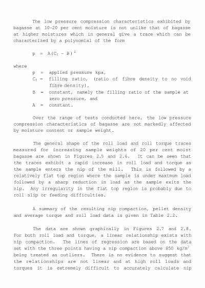
The low pressure compression characteristics exhibited by bagasse at 10-20 per cent moisture is not unlike that of bagasse at higher moistures which in general give a trace which can be characterized by a polynomial of the form
p = A(Cf - B )2
where p = applied pressure kpa, Cf = filling ratio, (ratio of fibre density to no void
fibre density),
B = constant, namely the filling ratio of the sample at zero pressure, and
A = constant.
Over the range of tests conducted here, the low pressure compression characteristics of bagasse are not markedly affected by moisture content or sample weight.
The general shape of the roll load and roll torque traces measured for increasing sample weights of 20 per cent moist bagasse are shown in Figures 2.5 and 2.6. It can be seen that the traces exhibit a rapid increase in roll load and torque as the sample enters the nip of the mill. This is followed by a relatively flat top region where the sample is under maximum load followed by a sharp reduction in load as the sample exits the nip. Any irregularity in the flat top region is probably due to roll slip or feeding difficulties.
A summary of the resulting nip compaction, pellet density
and average torque and roll load data is given in Table 2.2.
The data are shown graphically in Figures 2.7 and 2.8.
For both roll load and torque, a linear relationship exists with
nip compaction. The lines of regression are based on the data
set with the three points having a nip compaction above 850 kg/m3
being treated as outliers. There is no evidence to suggest that
the relationships are not linear and at high roll loads and
torques it is extremely difficult to accurately calculate nip

F I G U R E 2.5 T Y P I C A L ROLL LOAD CURVES FOR 20 PER CENT M O I S T U R E
B A G A S S E .
FIGURE 2.6 TYPICAL ROLL TORQUE CURVES FOR 20 PER CENT MOISTURE
BAGASSE.
12.


300 400 500 600 700 800 900 1000 1100
NIP COMPACTION kg/cu m
F I G U R E 2*7 T H E E F F E C T O F N I P COMPACTION O N ROLL L O A D .
FIGURE 2.8 THE EFFECT OF NIP COMPACTION ON ROLL TORQUE.
14.

15.
compactions. Reference to Figures 2.5 and 2.6 also suggest the likelihood of roll slip on the blanket of bagasse which further complicates the accuracy of the nip compaction measurements. The best pellet density achieved in these preliminary tests was 522 kg/m3 at a nip compaction of 796 kg/m3, the average density was about 390 kg/m3 . At the time of completion of these tests, the results seemed quite promising. it was expected that an improvement in pellet density would result when the compressed mat of bagasse was held under load for a particular retention time as specified by the pelleting work carried out by the University of Queensland.

CHAPTER 3
THE PELLETING MILL
3.1 CONSTRUCTION
Functionally, the pelleting mill was based on the two roll
cane milling unit which was used in the initial feeding experi
ments (see Chapter 2). For the pelleting mill, the hydraulic
pusher/feeder was removed and replaced with a three roll feeder
connected to the two roll mill by a pressure feeder chute. A
discharge chute and retention conveyor were designed for install
ation after the main two roll mill. Figure 3.1 shows the funct
ional layout of the complete pellet mill. Figure 3.2(a) shows
the completed pressure feeder and main mill assembly, while
Figure 3.2(b) shows the assembled retention conveyor. The values
for the major operation parameters and the dimensions of the
principal components are given in Table 3.1. The top main roll
and top pressure feed roll were supported in special strain
gauged bearing housings so that roll load could be measured. The
drive shafts to those roll were also instrumented to enable
torque to be measured. The pellet mill operated at a fixed
speed.
3.2 OPERATION AND MAJOR OPERATIONAL DIFFICULTIES
During each test, bagasse dried to the required moisture
level was fed manually onto a constant speed conveyor that moved
the bagasse up to the top of the feed chute, A levelling kicker
shaft was mounted above the conveyor to produce an even bagasse
height on the belt. Two bagasse sensors in the feed chute sensed
the height of the bagasse in the chute and switched the feed
conveyor on or off as required. Conventional conductivity
sensors do not adequately sense the presence of low moisture
bagasse. Hence two specially designed rotating arm sensors were
constructed which physically detected the presence of the bagasse
when the bagasse stopped them rotating.


1 9 .
FIGURE 3.2 THE COMPLETED PELLETING MILL.
(a) The pressure feeder and mill unit.
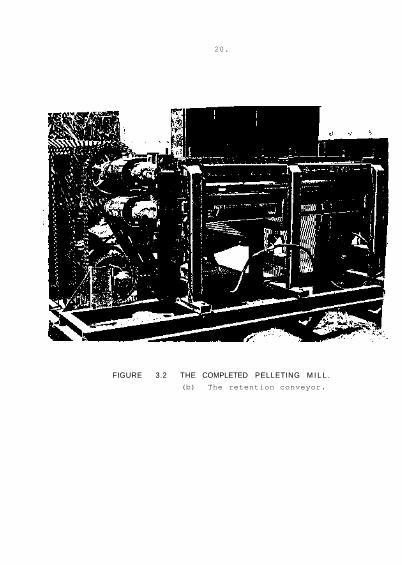
FIGURE 3.2 THE COMPLETED PELLETING M I L L .
(b) The retention conveyor.
20.

21.
TABLE 3.1 PELLET MILL COMPONENT SIZES.
(1) See Figure 3.1.

22.
The bagasse was dried in the Institute's experimental
bagasse dryer (Cullen and Mason, 1982) and stored in large
airtight plastic bags. When a warm bagasse feed was required,
the dryer and pellet mill were operated together. In general,
however, the bagasse was at ambient temperature. Bagasse dried
during both 1983 and 1984 seasons was used. No practical
operating differences between the bagasse from different years
was detectable in the results. In general, the very dry bagasse
(less than 10 per cent moisture) was from the 1983 season. This
bagasse had been stored in a dried condition for nearly one year.
The bagasse was drawn from the base of the feed chute and
passed through the pelleting mill. When reasonably dense pellets
were being made, a marked squeaking noise was produced in the
pressure feed chute (and delivery chute, if one was in use).
This noise is presumably associated with the usual slip/stick
motion of compressed bagasse over a metal surface.
The operation of the pellet mill was never entirely
problem free. The major difficulties involved poor feeding
behaviour, high frictional forces between the bagasse and the
stationary plates or chutes within the mill and problems with
scraper plate teeth.
Feeding Problems: It was very difficult to maintain a constant
flow through the mill under some conditions. The problem became
more severe with the very dry bagasses and as the feed height in
the feed chute decreased. The problem was exacerbated by the
very low density of dried bagasse and uneven filling of the feed
chute. The feed in the chute often contained voids or areas of
very low density on the "upper" surface of the inclined chute.
When these voids reached the pressure feed nip, there was often
insufficient feeding force to continue to push the bagasse into
the pressure feed chute, and bagasse flow would stop (i.e. the
rolls would slip on the bagasse). Considerable changes in mill
feed geometry (including an increase in underfeed roll size from
505 mm diameter to 750 mm and some weld roughening on the
pressure feed rolls) failed to cure the problem.

23 .
High Bagasse Friction Forces; The more fundamental experimental
work undertaken in the Mechanical Engineering Department,
Queensland University in parallel with this investigation, showed
that the coefficient of friction between dry bagasse and rust-
free, smooth steel is quite high and tends to increase as the
bearing pressure increases. This problem manifested itself in
the behaviour of the bagasse in the pressure feed and delivery
chutes.
In the pressure feed chute, if a test was performed with
the mill empty of bagasse at the start, the behaviour of the
bagasse changed noticeably as bagasse density increased (with a
corresponding decrease in bagasse speed along the chute). The
final (steady state) condition of the bagasse along the chute was
also quite sensitive to the details of the pressure feeder plate
shape. In early tests where there was quite marked convergence
toward the front of the pressure feed chute, the bagasse density
there built up to a level that required the use of a large wood
drill bit to remove it. Once the convergence was reduced to the
minimum required to enable the nose teeth on the plates to be
adequately fitted to the roll, the bagasse density decreased
markedly.
A further manifestation of the high friction forces
occurred when a short (100 mm) delivery chute was fitted to the
exit of the mill (no retention conveyor used). In this case, the
friction was sufficient to prevent the mill rolls from pushing
the bagasse through the delivery chute and caused the delivery
chute to be pushed away from the mill. Eventually, it caused the
top mill roll to "roll forward" on the bagasse blanket and
destroy both instrumented bearing housings.
Scraper Plate Teeth: It was very difficult to produce teeth on
the nose of the pressure feed and delivery chute plates that
would provide adequate scraping (groove cleaning) action and be
strong enough not to bend back under the action of the scraping
forces. The problem may have been due in part by the high
bagasse densities and large friction and pressure forces.
However the small size of the rig and the lack of ready access to

24.
fit the scraper teeth did not make the task any easier. The
final configuration for the nose of the pressure feed plates was
for chisel shaped (i.e. flat nosed) scrapers that fitted only the
top half of the grooving. On the delivery chute, the plates
finally used initially had no teeth but were fitted tightly to
the roll grooving so that when the roll was turned, the grooves
machined themselves into the leading edge of the delivery chute
plates.
The retention rig was used for a period in some of the
very early trials (late August 1984). However, the problems
outlined above, gradually became dominant and use of the delivery
chute and the retention rig was not achieved after that time.
3.3 EXPERIMENTAL RESULTS
The construction of the pelleting mill was completed
during August 1984 and initial commissioning runs undertaken
using the complete mill, including retention conveyor. As it
turned out, these were to be the only runs that were successfully
undertaken with the retention conveyor attached to the pelleting
mill.
The bagasse rate through the mill was below design
expectations. At the same time other feeding problems gradually
became apparent. Consequently an extended period was spent
investigating those problems and attempting to increase the feed
rate up to the design figure of 0.75 tonnes per hour. The main
effort concentrated on the feed rolls and feed chute area. At
one stage a larger (750 mm) diameter underfeed roll was fitted.
Unfortunately, this not only failed to increase the feed rate but
actually created additional feeding problems. Eventually the
original smaller (505 mm) diameter underfeed roll was placed back
into service and a decision made to investigate pelleting
performance with the five roll mill, initially without the
delivery chute and retention. These two items were to be added
as conditions permitted. Some tests were subsequently performed
with the delivery chute.

25.
3.3.1 Results with the Retention Conveyor in Use
The principal results for the test runs using the
retention conveyor are given in Table 3.2. It must be stressed
that these were intended to be commissioning tests. Hence the
results are not as complete and comprehensive as would be
desirable. However, they do show the effect of varying retention
time as illustrated in Figure 3.3.
FIGURE 3.3 VARIATION IN PELLET FIBRE DENSITY WITH RETENTION
TIME. (Retention Pressure 50 kPa)
Only one data point with "zero" retention time is
available. (This sample actually passed through the retention
conveyor, but no retention pressure was applied to it.) The
results suggest that when retention pressure is applied in the
(approximately) 90 seconds the bagasse pellet is in the retention
conveyor it has achieved about 60 to 70 per cent of the increase
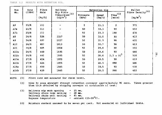
TABLE 3.2 RESULTS WITH RETENTION RIG.

to the final density that it would have achieved if it had been
held in retention for an extended period (i.e. about 15 minutes).
The exponential curve shown on Figure 3.3 is placed there for
reference only. It is not a statistically produced curve of
"best" fit. It was chosen somewhat arbitrarily to pass through
the three points (375 kg/m3, 0 sec); (450 kg/m , 100 sec) and
(485 kg/m ; 1000 sec). It thus ignores the single data point at
2.3 x 10 seconds (64 hours).
No data are available for retention pressures other than
50 kPa and no attempts were made to optimise the setting of the
delivery chute. It is possible that the retention pressure in
the delivery chute dropped to near zero at times because no
attempt was made to optimise the chute settings. The University
of Queensland experimental data indicate the resultant pellet
density would be reduced under these circumstances.
3.3.2 Results of Final Test Series
Eight groups of test (covering a total of 52 individual
tests) were conducted in the final test programme. Brief details
of each ,group of tests will now be given. Detailed results are
tabulated in Appendix I.
Series 1 Tests
Tests A to H
These tests were conducted to ensure that the rig was
working adequately and were intended to be the last tests using
the one year old, very dry 1983 season bagasse. The majority of
the subsequent tests used the current season (1984) dried
bagasse. (The exception are those tests with bagasse moistures
below 10 per cent.) In practice, no difference was found between
results obtained with 1983 or 1984 bagasse.
Fibre feed rates and pellet densities from this series
were significantly above those obtained in the next few test
groupings.

Series 2 Tests
This series of tests was carried out to investigate a
series of variables on performance of the rolling machine.
Influence of Delivery Compaction on Pellet Fina1 Density
(Tests 1 - 7 )
This was a series of tests carried out at an average of
13.5 per cent moisture (range 10.6 to 18.1 per cent) in which the
delivery nip setting was gradually adjusted until delivery nip
fibre compactions were approximately equal to the nominal design
level of 1 100 kg/m3 . These tests were carried out without
retention and the relationship between delivery compaction and
pellet fibre density is shown in Figure 3.4.
Influence of Feed Bagasse Moisture on Pellet Final Density
(Tests 8 - 17)
These tests were designed to investigate a range of feed
bagasse moistures at nominally fixed delivery compaction.
Feeding problems again became apparent at low bagasse moistures.
The top and bottom surfaces of the pellet also began to adhere to
the rolls. When this adhesion became severe it was difficult to
take a pellet sample that was good enough to have its density
determined. During this test group, flat scrapers were fitted to
the delivery rolls 90 degrees around from the nip. These
scrapers ensured that no bagasse carried right around the roll
and reduced the effective nip opening on subsequent passage
through the nip. They also ensured that all bagasse passing
through the nip could be collected to enable accurate bagasse
rates to be determined. The influence of moisture content of
bagasse on average fibre density of the pellets for each test is
illustrated in Figure 3.5. Mean delivery compaction for these
tests was 1 020 kg/m with a delivery work opening of 13.5 mm.

FIGURE 3.4 RELATIONSHIP BETWEEN DELIVERY COMPACTION AND FINAL
PELLET DENSITY, AVERAGE 13.5% MOISTURE - No RETENTION.
FIGURE 3.5 RELATIONSHIP BETWEEN FEED BAGASSE MOISTURE AND FINAL
PELLET DENSITY - MEAN DELIVERY COMPACTION 1 020 KG/M3,
29.

30.
Influence of Delivery Nip Compaction on Pellet Final Density
(Tests 18 - 21)
A series of tests was carried out with increased delivery
nip compactions by reducing the delivery nip setting from 13.5 to
11.5 mm. Average delivery nip compactions increased from
1 020 kg/m3 to 1 330 kg/m3. The problem of the pellet adhering
to the roll became severe during these tests and the series was
therefore limited. The results obtained are shown in Figure 3.5
and show that the reduced setting had virtually no effect on
final pellet density.
Attempts to Overcome Roll Adhestion Problems
(Tests 22 - 27)
As a result of the severe roll adhesion problem, a
decision was made to fit a short (100 mm long) delivery chute in
an attempt to produce good quality pellets. The chute nose
setting was 30 mm with an exit setting of 31.5 mm. These
settings were chosen in an attempt to obtain pellet densities of
about 400 kg fibre/m3 . (For tests 19 and 21, where pellet
densities of about 365 kg fibre/m3 were achieved, the pellet
thickness averaged just under 35 mm. These tests used low
moisture (14 per cent and 7 per cent) bagasses. With higher
moistures, the pellets were thicker (e.g. Test 20, 23 per cent
moisture, 46 mm thick).
The nose of delivery chute plates was found to be turned
up after tests 23 and 25.
During these tests a problem occurred with the relative
movement of the top delivery roll and the associated
scraper/chute plates. This problem was eventually traced to the
failure (fracture) of the specially instrumented shaft bearing
housing. The bearing housing was subsequently repaired and made
'rigid'. Only the bottom plate of the delivery chute was used
for the remaining tests. The results of these tests are shown in
Figure 3.6.
31.
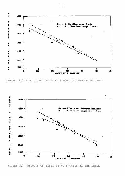
FIGURE 3.6 RESULTS OF TESTS WITH MODIFIED DISCHARGE CHUTE
FIGURE 3.7 RESULTS OF TESTS USING BAGASSE EX THE DRYER
32.
Influence of Temperature on Final Pellet Density
(Tests 28 - 37)
This was a group of tests intended to show up any effects
due to using warm bagasse (straight from the bagasse dryer)
rather than bagasse that had been dried for several weeks and was
at ambient temperature. However, the temperature losses between
the exit of the dryer and entry to the pellet mill vere larger
than expected and consequently, the average difference in pellet
temperature between the "cold" and "warm" bagasse was only 5
degrees Centigrade. There was no detectable difference in pellet
quality or density as illustrated in Figure 3.7. It was,
however, interesting to note that even the "cold" bagasse heated
up in its passage through the mill due to the amount of physical
work done on it. Thus "cold" bagasse feed temperatures were
generally about 31 degrees Centigrade but pellet temperatures up
to 39 degrees were recorded. Pellet temperatures increased as
each run progressed because the heat loss to the rolls and chute
plates decreased as they heated up during the test.
Investigations to Enhance Throughput
(Tests 38 - 46)
Following test 37, a major review of the experimental data
available at that time was undertaken and possible future work
reviewed. Three principal decisions were made.
(1) The first concerned further tests on the mill as it was then
being operated. It was noted that the early runs in the
test series (i.e. Series 1, Tests A to H) exhibited higher
fibre throughput rates and higher pellet densities than had
been achieved subsequently. Hence, this group of tests
(i.e. Tests 38 to 46) were conducted in an attempt to repeat
those higher values. The first part of the group (Tests 38
to 43) comprised pairs of tests in which runs with both high
and low feed chute levels were made on the same batch of
bagasse. Two of these tests with high feed chute levels
(see tests 41(a) and 42(a), Appendix 1) achieved fibre rates
above 500 kg/h which were quite close to the higher feed
33.
rates achieved in the Series 1 tests (see tests B, D and E).
However, pellet densities were nowhere near as high (280 to
320 kg fibre/m3 in tests 38 to 43 compared with 370 to 560
kg fibre/m3 in tests A to H).
In a final attempt to obtain the higher pellet densities,
the feed chute was changed to one that had divergence in
both cross-section dimensions from top to bottom. (The
chute used prior to this was nominally parallel in width.)
(2) The second decision was to check on the profile of the
divergence in the pressure feed chute and to adjust it to be
as nearly as possible the same as that which applied to the
Series 1 tests. For good scraping action, the teeth on the
nose of a scraper plate must be bent "into" the grooves so
that there must be a short convergent section. In the
Series 1 test situation, that convergent section was about
70 mm long and asymmetrical on the top and bottom plates.
Before the start of Series 2 tests, the plates were
"corrected" to give a smaller symmetric convergent length
(about 20 mm). For this final test group, the length of
convergence was again increased, although this time it was
nearly symmetric on top and bottom plates. It is awkward to
quantify that convergent-divergent shape because measure
ments within the assembled pressure feed chute are very
difficult to make. The best indication of it was obtained
by placing a straight edge along the length of the plates.
For this final test group, the divergence from the straight
edge started 70 mm from the tip of the scraper nose and was
a maximum of about 10 mm at the nose.
The feed rates obtained in these tests (44 - 46) averaged
493 kg/m3 and final fibre densities averaged 354 kg/m3.
The results of all the tests performed are given in
Appendix 1. The major results are plotted in Figures 3.8 and
3.9. All data from this final test series are displayed on these
graphs.

FIGURE 3.8 VARIATION IN BAGASSE FEED FIBRE RATE WITH FEED
MOISTURE LEVEL
34.

FIGURE 3.9 VARIATION IN PELLET FIBRE DENSITY WITH PELLET
MOISTURE
35.

36.
Figure 3.8 plots the feed fibre rate against the moisture
content of the feed bagasse for all tests. It illustrates the
increasing feed rate as feed moisture decreases with a large
scatter with feed moistures below 10 per cent. The fibre rate
averaged over all tests was 410 kg/h. If the data had been
plotted as bagasse rate (rather than fibre rate), then above
about 10 per cent bagasse feed moisture, the feed rate was
approximately independent of moisture with an average of about
475 kg/h (range from 440 to 510 kg/h).
Figure 3.9 shows the variation in pellet
fibre density with pellet moisture content for
all tests. The linear regression line is shown (all available
data used). This has the
form
Pellet Fibre Density = 491.6 - 11.82 x (Pellet
Moisture (%))with r2 = 0.6193
and residual standard error = 45.94.
If a multiple regression of pellet density against pellet
moisture and delivery nip fibre compaction is carried out, the
resulting relationship is
Pellet Fibre Density = 428.3
+ 0.0660 x (delivery nip fibre
density)
- 13.46 x (pellet moisture)
with r2 = 0.6395
and residual standard error = 44.95.
This is not a very great improvement in precision compared to the
single regression. It indicates that a change of 100 kg fibre/m3
in the delivery nip density results in a 6.6 kg fibre/m3 change
in pellet fibre density under the pelleting conditions applying
to these tests. A ten per cent decrease in bagasse moisture

37.
results in an indicated 135 kg/m3 increase in fibre compaction.
(Note that in the single regression, a 10 per cent moisture
decrease only indicates a fibre density increase of 120 kg/m3).

39.
CHAPTER 4
ESTIMATION OF FORCES THROUGH ROLLERS AND CHUTES
4.1 INTRODUCTION
The results outlined in Chapter 3 have illustrated the
significant effect that the chute configurations have had on
performance of the pelleting machine. It was therefore decided
to undertake a fairly simplistic analysis of bagasse pressures
and frictional forces in the region of the delivery rolls and
delivery chute of the pelleting machine in an attempt to obtain a
better understanding of the influence of chute parameters on the
forces in the pellet and the subsequent pellet fibre density.
4.2 MODEL FOR HORIZONTAL PRESSURES
Computations of typical longitudinal bagasse pressures
attained during the pelleting experiments were made. The basis
of the calculations for the two roll mill was the relations found
in Chapter 2 of Murry and Holt (1967). These were developed for
the feeding region of a roll pair. These relationships are a
good approximation in the entry or feed region of such a roll
pair where the longitudinal pressures are low. The longitudinal
pressure however is significant in the region of the nip of the
rolls and the analysis of Murry and Holt is not generally
adequate because an analysis of the mechanics of rolling shows
that the phenomenon of "reabsorption" occurs. (The mechanism of
"reabsorption" is not fully understood and a detailed discussion
of it is beyond the scope of this exercise. However it is the
name used to describe the phenomena whereby more material passing
through the nip of a pair of rolls than is indicated by direct
geometric calculation.) Never-the-less, in this instance, the
theory of Murry and Holt was used partly because it was felt it
would give adequate precision for the purposes of this exercise
and also because an analysis of the data in Appendix I showed no
reabsorption was occurring except with the highest delivery
40.
compactions. (At a delivery work opening of 11.5 mm, average
delivery nip compaction 1 250 kg/m3, the average reabsorption
factor was only 1.09.)
On the assumption that the rolls can exert the full
frictional force on the bagasse during the rolling action it is
possible to calculate the maximum discharge pressure that can be
achieved from the roll pair. For the delivery chute, a one
dimensional chute theory was devised.
The purpose of these computations was to examine the
effects of varying some of the rig geometry parameters. Whilst
it is recognised that the model would overestimate pressures it
was felt that the models employed were sufficiently refined to at
least indicate major trends correctly.
None of the feeding configuration parameters was varied so
it was necessary only to examine the two roll mill itself and the
associated exit chute. A bagasse pressure zero was assumed at
the plane of the feed entry angle (30°) of the delivery rolls.
Computations were based on whole bagasse of 10 per cent moisture
at 20°C. Two values of mill work opening were considered
corresponding to delivery compactions of 1 100 and 900 kg/m3.
Three values of delivery angle (7, 12 and 15 degrees) and three
values of exit chute length were considered. The compression
characteristics of bagasse were those established during
sinusoidal tests described in Chapter 5 of the University of
Queensland component of the report. Peak pressures at 1 100 and
900 kg/m3 compaction were 37.4 and 16 MPa respectively.
Frictional data were those obtained during tests described in
Chapter 7 of the University of Queensland component of the
report.
Based on these data the results shown in Figures 4.1 and
4.2 were obtained. Figure 4.1 illustrates the very significant
effect that delivery compaction (and work opening) has on maximum
discharge pressure. As was anticipated, the predicted bagasse
pressures were higher for the smaller work opening. It is of
interest that the discharge pressure of the mill fell with rising
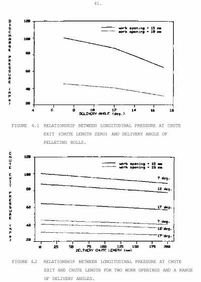
FIGURE 4.2 RELATIONSHIP BETWEEN LONGITUDINAL PRESSURE AT CHUTE
EXIT AND CHUTE LENGTH FOR TWO WORK OPENINGS AND A RANGE
OF DELIVERY ANGLES.
FIGURE 4.1 RELATIONSHIP BETWEEN LONGITUDINAL PRESSURE AT CHUTE
EXIT (CHUTE LENGTH ZERO) AND DELIVERY ANGLE OF
PELLETING ROLLS.
41.
42.
delivery angle. It must be remembered however that the
assumption of full friction always acting is made in the
representation of the mill. The longtudinal force of the bagasse
must thus always increase with the delivery angle. The
increasing delivery area means that there is actually a drop in
the discharge pressure as the delivery angle is raised in this
case. The effect of the chute length is seen to be a pressure
drop which increases with chute length as illustrated in Figure
4.2.
During the tests carried out with the pelleting plant it
was found that "reabsorption" was not occurring except at high
levels of delivery compaction (11.5 mm delivery work opening).
When horizontal pressures were calculated for the 11.5 mm work
opening as outlined above (i.e. ignoring reabsorption) a
discharge pressure of 197 MPa was predicted. The discharge
pressure of the mill was also calculated with acknowledgement of
the occurrence of reabsorption. It was assumed that the bagasse
flowed forward over the roll surfaces from the neutral plane to
one half of the angle of the neutral plane past the nip of the
mill. A constant pressure of that at the neutral plane and a
change in sign of the coefficient of friction were used to
represent this extrusion type process. The original model was
reverted to for the region from the estimated end of the
reabsorption to the delivery angle. In this manner, a discharge
pressure of only 42 MPa was predicted.
4.3 DISCUSSION
The rather simplistic approach to examination of the
potential horizontal forces developed in the rolling pelleting
machine has illustrated the sensitivity of the rolling unit to
chute configuration, delivery roll compaction, and potential
effects of "reabsorption". The analysis helps to qualitatively
explain some of the variation in compaction and throughput
obtained but offers little information on how to predict better
discharge densities. The analysis has illustrated the high
values of horizontal pressures developed relative to the vertical
pressure applied by the roller.
43.
CHAPTER 5
CONCLUSIONS
The design concept for the pelleting machine envisaged a
capacity for the pilot plant pelleter at its nominal design speed
of 36 mm/s of 0.75 tonne fibre per hour producing pellets at a
final fibre density of at least 500 kg/m3.
Tests on the machine that was constructed have shown that
stable pellets can be produced but that the best performance
under test conditions fall short of the design estimates. In the
tests carried out the maximum throughput achieved was 540 kg/m3
and maximum pellet final fibre densities was 530 kg/m3.
The sensitivity of the quality of pellets produced to the
moisture content of bagasse established in previous batch testing
was confirmed in the rolling pilot plant. In practice it would
not be practical to attempt to pellet by rolling, material with a
moisture content greater than 15 per cent, if high densities and
fibre rates were required.
Whilst the pilot plant pelleter has been able to produce
acceptable pellets the limiting factor in its ability to achieve
its nominal design capacity has been the inability to establish
the conditions to feed the low density dry bagasse at an accept
able rate, to accommodate the high bagasse friction forces in the
pressure feed chute, and to optimise the geometry of the
discharge chute. The University of Queensland tests established
that high values of coefficient of friction existed for dry
bagasse and consequently high horizontal forces could be
developed. Whilst these forces can enhance the pellet density
further work is required to establish an effective nose plate
configuration which gives better removal of the bagasse from the
rollers.
Before the design can be fully commercialised further work
is required to optimise chute configurations in conjunction with

44.
retention. It is proposed to explore, in conjunction with a
potential manufacturer, the possibility of obtaining an
Australian Industrial Research and Development Incentives Board
project grant for this further development work.

45.
REFERENCES
Cullen, R.N. and Mason, V. (1982). Final Report. Elimination of
Use of Fuel Oil for Steam Generation in the Sugar Industry -
Part 1.
Murry, C.R. and Holt, J.E. (1967). The Mechanics of Crushing
Sugar Cane. Elsevier.


47.
APPENDIX I
EXPERIMENTAL RESULTS
Table I.1 lists all results obtained during the final test
series. Details of the test groupings within this series of
results are given in Section 3.3.2, and the major graphical
results are presented in Figures 3.8 and 3.9.

