final report imaging-from spinning spacecraft · bayma. sections 1 - 9 and 11 of this report were...
TRANSCRIPT

N76-28452RADAR IMAGING FROM A(NASA-CR-137829) PINNING SPACECRAFT Final Report, 1 may - 1
ec. 1975 (Environmental Research Inst. of UnclasCSCL 171ichigan) 92 p HC $5.00 4783Ga/32
NASA CR-137829115200-2-F
NfAERIM,
Final Report
RADAR IMAGING-FROM A SPINNING SPACECRAFT
ROBERT W. BAYMA MOHAMED A. HIDAYET Radar and Optics Division
MARCH 1976
Prepared for NATIONAL AERONAUTICS AND SPACE
C i: TION
Ames Research Center Moffett Field, California Contract No. NAS2-8860
24035
T A LM ENn O0
SSEARCH V I N
INSTITUTE OF MICHIGAN FORMERLY WILLOW RUN LABORATORIES THE UNIVERSITY OF MICHIGAN BOX 61B0ANN ARROR*MICHIGAN 48107
https://ntrs.nasa.gov/search.jsp?R=19760021364 2019-02-13T15:48:11+00:00Z

TECHNICAL REPORT STANDARD TITLE PAGE 1 Report No. 2. GovernmentAccession No. 3. Recipient's Catalog No
NASA CR-137829 4. Title and Subtitle 5. Report Date
March 1976RADAR IMAGING FROM A SPINNING 6. Performing Organization Code SPACECRAFT
7. Author(s) 8 Performing Organization Report No. R. W. Bayma, M.A. Hidayet ERIM 115200-2-F
9. Performing Organization Name and Address 10 Work Unit No
Radar and Optics Division Environmental Research Institute of 11. Contractor Grant No
Michigan, P.O. Box 618 NAS2-8860 Ani Arbor, Michigan 48107 13. Type of Report and Period Covered
12. Sponsoring Agency Name and Address Final report Advanced Missions Office 1 May 75 - 1 Dec 75 NASA Ames Research Center Moffet Field, California 24035 14. Sponsoring Agency Code
15 Supplemenary Notes
16. Abstract
The objective of this study is to determine the feasibility ofimaging the surface of Venus using a synthetic aperture radar in a spin-stabilized Pioneer class spacecraft operating in an eccentric orbit. Imaging radar fundamentals, constraints, power requirementsand data processing considerations are reviewed in Sections 2 through 6. Additional effects due to operation from an elliptical orbit with a spinning spacecraft are covered in Sections 7 through 9. Recommended spin parameters are determined by simulations presentedin Section 10. Extensions to includenoncoherent integration and stereo coverage are briefly reviewed in Section 11.
The results of this study indicate that resolution on the order of 100 meters can be obtained from a 0.2 eccentricity orbit using a 2 meter antenna and-reasonable transmitter power levels.
17. Key Words 18. Distribution Statement Imaging radar Synthetic aperture radar Venus orbital imaging radar
19. Security Classif. (of this report) 20. Security Classif. (of thispage) 21. No. ofPages 22. Pi Ice
Unclassiie Unclassified 92

L RIM FORMERLY WILLOW RUN LABORATORIES. THE UNIVERSY OF MICItOAN
PREFACE
This report was prepared by the Radar and Optics
Division of the Environmental Research Institute of Michigan
(ERIM), Ann Arbor, Michigan, under contract No. NAS2-8860
with NASA Ames Research Center, Moffett Field, California.
This report describes work performed between 1 May 1975 and
1 December 1975. The effort was monitored by Larry E. Edsinger,
Advanced Mission Office, NASA Ames Research Center. The
ERIM number for this report is 115200-2-F.
The Principal Investigator for this study is Robert
W. Bayma. Sections 1 - 9 and 11 of this report were written
by R. W. Bayma. Section 10 was written by M. A. Hidayet.
Additional contributions to this study were made by C. C.
Aleksoff. The authors are also grateful to Robert C. Heimiller
for his constructive review of the draft version of this
report.
3

RUMERLY WILLOW RUN LABORATORIES. THE UNIVERSTY OF MICNIGAH
SUMMARY
Recent NASA studies have been conducted to determine the feasibility of-imaging the Venusian surface using an orbiting synthetic aperture radar (SAR).
The earliest studies on orbital radar imaging have emphasized mapping from a circular orbit. This method simplifies the radar system since processing parameters-remain constant. However,-because of spacecraft propulsion constraints,
and data transfer considerations, it-can be advantageous to operate from an elliptical orbit.
Significant problems associated with SAR imaging.from a highly elliptical orbit include the compensation for a large, varying, time delay and radial-velocity-induced Doppler frequency shift; transmit-receive interlacing over a large change in slant range; and large change in azimuth focal parameters. However, these problems are reduced by using a batch processing mode.
Previous studies utilized a three-axis stabilized spacecraft. A planned Pioneer Venus Orbiter mission uses a less expensive spin-stabilized spacecraft for altimetry and coarse resolution imaging. The purpose of this study is to determine the feasibility of obtaining improved resolution on the order of 100 meters from a spin-stabilized Pioneer class spacecraft. This report begins with a review of.imaging radar fundamentals, and proceeds to discuss restrictions encountered with a spinning spacecraft.
For coherent radars, range resolution is determined by RF bandwidth, and azimuth resolution is determined by the coherent integration time or synthetic aperture length. The coherent integration time can correspond to a single pulse, or to the total interval covered by a number of pulses processed
4

LZ RIM FORMERLY WILLOW RUN LABORATORIES THE UNIVERSITY OF MICHGA
for unfocused or focused synthetic aperture radars. In the
later case, the total synthetic aperture length is limited
by the target illumination time, which is equal to the
transit time through the real antenna beam for a 3-axis
stabilized spacecraft, or is equal to the time-on-target during
a scan for a spin-stabilized spacecraft.
When operating from an elliptical orbit with a limited
antenna aperture, delay-Doppler ambiguity constraints limit
coverage at the higher altitudes and shallow grazing angles.
Power requirements may also limit coverage at the higher
altitudes.
Because the data is collected in bursts, batch mode
processing will be required. On-board processing will be
limited to Doppler tracking, which will be required to com
pensate for the change in instantaneous Doppler center fre
quency due to antenna scanning and spacecraft radial velocity,
and PRF buffering. For 6 bit quantization, the telemetry
data rate is approximately 180 kbps. The PRF buffer storage
is 3 kbits and the total buffer storage for a spin cycle is
3 Mbits.
Azimuth correlation would be done with a ground based
digital processor. Range pulse compression would be done
either in the spacecraft or with the ground processor.
Performance results are given for three principle spin
axis orientations: 1) in the orbital plane, 2) normal
to the orbital plane, and 3) a third general orientation.
A computer program was developed which calculates the mapping
parameters, the power requirements, and the surface longitude
5

and latitude of the target point for a given circular antenna
aperture diameter, antenna mounting angle and a spin vector.
A modified version calculates the same parameters when the
angular orientation of the antenna is continuously directed toward the direction of maximum grazing angle. Sinc, the
optimal mapping parameters and minimum power requirement
occur at the direction of maximum grazing angle, the modified version generates the envelope for the curves generated during
individual spin cycles.
The results obtained from this study indicate that by placing the spin axis normal to the orbital plane and the
antenna mounting angle such that the boresight is 10 to
15 degrees off nadir, complete planet coverage at 30 to
160 meter azimuth resolution is attainable. The average
operating transmitter power required for a SNR of 10 dB is 10
to 200 watts during a nominal 120 msec mapping interval once
per spin cycle. The average power over a 12 second spin cycle
is 0.1 to 2 watts.
The results of this study demonstrate mission feasibility. A baseline design study is recommended to optimize
the selection of orbital and radar parameters and to in
vestigate processing algorithms in detail.
6

FORMERLY WILLOW RUN LABORATORIES, THE UNIVERSITY OF MICHIGAN Z jIRIM
CONTENTS
1. Introduction . .......................................13
2. Imaging Radar Fundamentals ......................... 15 2.1 Introduction................................... 15
2.2 Range Resolution ................................ 16 182.3 Azimuth Resolution .............................
2.3.1 Noncoherent Imaging Radar ............... 18 2.3.2 Single Pulse Doppler Beam Sharpening ... 19
2.3.3 Coherent Pulsed Doppler Radars ........... 23
2.4 Synthetic Aperture Radar ....................... 25
3. Synthetic Aperture Radar Resolution ................ 27
3.1 Introduction ................................... 27
3.2 Angular Resolution of a Synthetic Array........ 27
3.3 Unfocused Synthetic Aperture ................... 31
3.4 Focused Synthetic Aperture ..................... 32
4. SAR Ambiguity Constraints ........................... 35 354.1 Introduction ...................................
4.2 Azimuth Aperture Constraint..................... 35
4.3 Elevation Beamwidth Constraint ................. 36
4.4 PRF and Time Bandwidth Constraint .............. 37
395. SAR Power Requirements ..............................
6. Data Processing...................................... 45 6.1 Introduction ................................... 45 6.2 Continuous Processing .......................... 45 6.3 Batch Processing ............................... 47
486.4 Data Rates......................................
7. Elliptical Orbit Considerations ..................... 53 537.1 Introduction....................................
............. 537.2 Resolution ...................... 7.3 Ambiguity Constraints .......................... 53
7.4 Power Requirements.............................. 54 7.5 Data Processing ............................... 54
8. Spinning Spacecraft Considerations .................. 55
8.1 Introduction.................................... 55 8.2 Resolution ....................................... 55 8.3 Ambiguity Constraints .......................... 60
7

FORMERLy WILLOW SUN LABORATORIES THE UNIVERSrry OF MICHIGAN
8.4 Power Requirement. .............................60 8.5 Data Processing................................. 60
Comparison of Three-Axis Stabilized Spacecraft9. and Spinning Spacecraft Imaging Capabilities ........ 63 9.1 Introduction .................................... 63 9.2 Resolution...................................... 63 9.3 Ambiguity Constraints .......................... 64 9.4 Power Requirements.............................. 65 9.5 Data Processing ................................. 65
10. Recommended Spin Parameters ......................... 67 10.1 Introduction................................... 67 10.2 Effect of . .................................. 67 10.3 Effect of s .................................. 70 10.4 Simulation. ................................... 70 10.5 Spin Axis in the Orbit Plane .................. 71 10.6 Spin Axis Normal to Orbit Plane................ 76 10.7 General Spin Axis Orientation ................. 82 10.8 Effects of Parameter Variations ............... 88 10.9 Conclusions .................................. .88
11. Extensions .......................................... 89 11.1 Noncoherent Integration ....................... 89 11.2 Stereo......................................... 90
References............................................... 91
92Bibliography.
8
FORMERLY WILLOW RUN LABORATORIES THE UNIVERSrY OF MICHIGANZLEIM
FIGURES
3-1. Synthetic Array Geometry .......................... 28
5-1. Terrain Backscatter Coefficient ................... 41 41
5-2. Ground Resolution .................................
67I. Continuous Processing ............................. 46
6-2. Batch Processing with Nonoverlapping Apertures .... 46
8-1. Planar Synthetic Array Geometry for a Spinning 56Spacecraft.........................................
10-1. Coordinate System (at periapsis).................... 68
10-2. Resolution for Spin Axis in the Orbit Plane ....... 72
103. Time-Bandwidth Product for Spin Axis in the Orbit 73Plane .............................................
10-4. Power Requirements for Spin Axis in the Orbit 74Plane..............................................
10-5. Ground Track for Spin Axis in the Orbit Plane ..... 75
10-6. Resolution for Spin Axis Normal to the Orbit 78Plane ..............................................
10-7 Time-Bandwidth Product for Spin Axis Normal to the 79Orbit Plane........................................
10-8. Power Requirement for Spin Axis Normal to the ......................................
10-9. Ground Track for Spin Axis Normal to the Orbit Plane.............................................. 81
10-10. Resolution for General Spin Axis Orientation ...... 83
10-11. Time-Bandwidth Product for General Spin Axis Orientation.......... :..............................84
10-12. Power Requirements for General Spin Axis 85 Orientation .......................................
10-13. Ground Track for General Spin Axis Orientation .... 86
9

OF MICHIGANRUN LAORATORIES. THE UNIVERSUYFORMERLY WILLOW
GLOSSARY
A antenna area
a(e) two-way antenna voltage gain
B Rf bandwidth
B Doppler frequency to first null of antenna azimuth
pattern
B azimuth Doppler bandwidth a
Doppler filter bandwidthBD
c velocity of propagation
azimuth compression ratioCA
range compression ratioCR
d antenna diameter
antenna azimuth aperture dimensiond a
de antenna elevation aperture dimension
e orbit eccentricity
fD Doppler frequency
h radar altitude
k Boltzmann constant
L RF and propagation losses
LA synthetic aperture length
number of pulses per synthetic aperture intervalNA
NB Buffer storage for a spin cycle
Buffer storage for pulse repetition periodNpRF
P average transmitter power
q quantized word size
R slant range
10

SIM FORMERLY WILLOW RUN LABORATORIES THE UNIVERSITY OF MICHIGAN
RAVE average video data rate
RB buffered video data rate
R minimum video data ratemin
RV raw video data rate
s(e) processed signal
S spacecraft spin rate
SNR signal-to-noise ratio
T coded pulse length
T Delay to first null of antenna elevation pattern
T Length of video return
TA coherent integration time
TM mapping time interval
TB time-bandwidth product
T effective receiver temperaturee
V radar velocity
VN radar velocity component normal to the line of sight
p radar velocity vector at periapsis
W azimuth patch length
x radar position along synthetic array
x position of radar at n-th pulse
Ba azimuth beamwidth a
Belevation beamwidthe
AfD Doppler bandwidth
AR slant range interval
AT uncoded pulse length
11

- FORMERLY WILLOW RUN LABORATORIES THE UNIVERSITY OF MICHIGANA IM
AT' compressed pulse length
Ax azimuth spatial sampling interval
Ae angular azimuth resolution
T1 antenna aperture efficiency
received phase of n-th pulse
angle between the projection of the spin vectoron the orbit plane and the radial position of the spacecraft at periapsis
0A angular synthetic aperture interval
om angle between antenna boresight and spin axis
pP angle between velocity vector and antenna boresight
0sangle between spin vector and orbit plane
eT angle between velocity vector and target line-ofsight
x RF wavelength
Pa azimuth resolution
Pg 'ground resolution
po azimuth resolution for a non-spinning spacecraft
@r slant range resolution
abackscatter coefficient0
*grazing angle
Op angular velocity of the antenna
angular velocity of the target line-of-sightT
12

.I~RIM FORMERLY WILLOW RUN LASORATORIES THE UNIVERSITy OF MICHIGAN
1
INTRODUCTION
Recent achievements in planetary exploration have in
cluded the collection of fine resolution visual imagery of the planets Mars and Mercury from various Mariner spacecraft. However, the cloud covered surface of the Earth's nearest neighbor planet, Venus, defies visual imaging systems.
Earth-based radar astronomy has permitted us to determine the rotation rate of Venus, and has also yielded coarse resolution radar reflectivity maps of the planet surface. Recent upgrading of the Arecibo radar site is expected to
permit resolutions of 1 to 2 km near the subradar point at inferior conjunction. However, the Mercury imaging missions
have demonstrated that surface resolutions of 100 m or less are required to identify important geological features. Hence, recent NASA studies [1-.] have been conducted to determine
the feasibility of imaging the Venusian surface using an orbiting synthetic aperture radar (SAR).
The JPL studies [2] on orbital imaging radar have emphasized mapping from a circular orbit. This method simplifies the radar system since processing parameters remain constant. However, a circular orbit is not necessary, since, unlike visual imaging systems, SAR resolution can be made independent of range. In addition, due to spacecraft propulsion constraints and data transfer considerations, it can be advantageous to operate from an elliptical orbit.
Significant problems associated with SAR imaging from a highly elliptical orbit include the compensation for a large
varying radial-velocity-induced Doppler frequency shift; transmit
13

FORMERLY WILLOW RUN LABORATORIES THE UNIVERSITY OF MICHIGANA
receive interlacing over a large change in slant range; and large
change in azimuth focal parameters. The Martin-Marietta-ERIM
study [4] demonstrated that these problems could be easily
handled by using a batch processing mode, since PRF, range
gating and other radar parameters can be changed at discrete
intervals as required.
Previous studies [l-4] utilized a three-axis stabilized
spacecraft. A planned Pioneer Venus Orbiter mission [5] uses
a less expensive spin-stabilized spacecraft for altimetry and
coarse resolution imaging. The purpose of this study is to
determine the feasibility of obtaining improved resolution on
the order of 100 meters from a spin-stabilized Pioneer class
spacecraft.
Nominal parameters used in this study are listed
below:
orbit eccentricity: 0.2
periapsis altitude: 500 km
maximum antenna diameter: 3 meters
spin rate: 2 to 30 rpm
wavelength: 10 cm
Orbit and spacecraft constraints were given by the Advanced
Missions Office, NASA Ames Research Center. The wavelength
was the same used in previous Martin-Marietta-ERIM studies
[3,4] .
This report begins with a review of imaging radar fun
damentals, and proceeds through a discussion of restrictions
encountered with a spinning spacecraft. Performance results
are given for three principle spin axis orientations: 1) in
the orbital plane, 2) normal to the orbital plane and 3) a
third general orientation.
14
OIGWAL PAGE IS POOR

L RIM FORMERLY WILLOW RUN LABORATORIES, THE UNIVERSITY OF MICHIGAN
2 IMAGING RADAR FUNDAMENTALS
2.1 INTRODUCTION
The principal imaging radar system is the sidelooking
airborne radar (SLAR) which obtains along-beam or range
resolution by measuring time delay between returns from
image elements; and obtains cross-beam or azimuth reso
lution by using a real aperture (narrow beam) antenna, or a
synthetic aperture (Doppler signal processing) technique.
Most SLAR systems operate at broadside in which the an
tenna is directed normal to the radar velocity vector, and
consequently, range resolution is cross-track and azimuth
resolution is along-track. This is not a fundamental re
quirement, since these radars can attain the same resolu
tion at any squint angle that is not coincident with the
velocity vector.
A second class of imaging radars is the microwave
hologram radar (HR) which attains cross-track resolution
using real aperture phased array techniques, and along
track resolution using synthetic array techniques. These
radars can image along and to both sides of the ground
track using an unmodulated (CW) signal. However, in order
to obtain fine cross-track resolution, the radar must be
operated at low altitude, or at moderate altitudes using
the shortest possible wavelength and largest possible
antenna aperture. Such a system would not be practical
for the Venus mapping mission, but is listed here for
completeness. Additional discussions on MHR systems are
given in References [6-f
15

EFORMERLYWILLOW RNLABORATORIE.THEOUNVERSYOF.MCHIGAN
In the following two'sub-sections, range and azimuth
resolution for imaging radars are discussed from the point of
.view of temporal signal processing and filtering theory.
In Section 3 of this report, SAR azimuth resolution is
further considered from the point of view of linear antenna
array theory.
2.2 RANGE RESOLUTION
The nominal slant range resolution attainable using
an uncoded rectangular pulse of length AT is
c AT (1)
where c is the velocity of propagation. The required RF
bandwidth is
BET (2)
The output signal-to-noise ratio (SNR) of any radar system is
proportional to the energy in the radar pulse. Consequently,
the required peak transmitted power for a specified signal-to
noise ratio is inversely proportional to pulse length. For a
fine resolution radar, the peak power requirements become
excessive if a simple rectangular pulse is used. Hence, a
longer coded pulse of length T and bandwidth B is used. By
processing the received signal with the appropriate matched
filter, the pulse can be compressed to an effective length of
16

FORMERLY WILLOW RUN LAORATORIE S THE UNIVERSITY OF MICHIGAN
1 AT' - B (3)
Then the effective slant range resolution is
C
Pr = (4)
The pulse compression ratio is
CR A T = TBRTT~(5)
The detailed structure of the compressed waveform
depends on both the waveform modulation and Doppler shift
of the return. This structure is usually given by the radar
ambiguity function which describes the interfering power
from targets at other ranges and Doppler shifts which
are present at the output of the filter matched to a speci
fied range and Doppler shift.
The most common types of coded waveforms used for pulse
compression are linear FM (chirp) signals and binary
phase codes. These signals can be generated and compressed
both actively and passively at RF, IF or video frequencies.
17

LERIM - ORMERLy WILLOW RUN LABORATORIES THE UNIVERSIY OF MICNIOAN
Slant range resolution is the projection of the ground
range resolution cell normal to the line of sight. Thus
pr = pg cos ~ r g C(6)
where ' is the grazing angle. Substituting Eq. (4) in (6),
the ground resolution can be expressed in terms of RF band
width and grazing angle as
pg = sec'p (7)
2.3 AZIMUTH RESOLUTION -
Azimuth resolution is defined in the mapping plane
determined by the radar velocity vector and the radar line
of-sight, and is measured normal to the radar line of sight.
Ground resolution is determined by the projection of the
azimuth resolution element along lines of constant Doppler
frequency, which are cones concentric with the radar velocity
vector.
2.3.1 NONCOHERENT IMAGING RADAR
In a noncoherent SLAR, the phase of the returned pulse
is not available, or is not used. In such a system, the
azimuth resolution is determined by the real aperture beam
width.
18

jLEIM FORMERLY WILLOW RUN LABORATORIES THE UNIVERSITY OF MICHIGAN
In this case
Pa R~a
-Ax RwU
a (8)
where S is the azimuth beamwidth and d is the azimuth a a
aperture dimension. Operational radars of this type are the
Motorola AN/APS-94 and the Westinghouse AN/APQ-97 imaging radars.
2.3.2 SINGLE PULSE DOPPLER BEAM SHARPENING
For the case of single pulse Doppler beam sharpening,
such as proposed for the planned Pioneer Venus Orbiter Radar
Mapper [5], the radar is required to be-coherent over the
length of the transmitted pulse. The spectrum of the returned
pulse is broadened by the Doppler spread of the illuminated
terrain. Azimuth resolution (Doppler beam sharpening) is
improved by filtering the returned signal prior to detection.
The azimuth resolution is determined by the bandwidth of the
Doppler filter.
The instantaneous Doppler frequency of a target at an
angle e from the vehicle velocity vector is
2V D - cose (9)
19

FORMERLY WILLOW RUN LABORATORIES THE UNIVERSITY OF MICHIGANA~ I
For small angles, the Doppler bandwidth is given by
M2VNAf D -= A0 (10) D (10
where
VN = V sin 8 (11)
is the radar velocity normal to the target line-of-sight.
The Doppler spread from homogeneous terrain for a radar
with azimuth beamwidth a is then
2VN a x a (12)
By processing the returned pulse with a Doppler filter of
bandwidth BD ' with BD < Ba, the angular resolution can be
improved to
AG V ED (13) N
20

'jIIM FORMERLY WILLOW RUN LASORATORIES THE UNIVERSITY OF MICHIGAN
The minimum attainable Doppler resolution is equal to the reciprocal of the pulse length T. Then
?e> N (14)
From Eqs. (13) or (14), the azimuth resolution is
Pa - 2VN D
> RX
NT (15)
Note that VNT is the distance the radar travels normal to the line-of-sight during the Doppler processing time.
In order to improve the azimuth resolution by Doppler
filtering, the pulse length must satisfy the inequality
VNT > da/2 (16)
that is, the "effective" aperture must be greater than half
the real aperture.
21

FORMERLY WILLOW RUN LABORATORIES THE UNIVERSITY OF MICHIGANRIM
If an uncoded pulse is used, the slant range resolution is
cT Pr = (17)
Then
RXcPa r
and the best attainable areal resolution is
pp = papr sec
RX c sec 4VN (19)
For the nominal parameters considered in this study, the
attainable resolution is on the order of 50 km by 50 km.
-By using a parallel bank of Doppler filters and a
sufficiently long pulse, the real azimuth beam can be sub
.divided into several resolvable synthetic beams, and a coarse
resolution radar image can be generated from the return of.a
single pulse. However, from Eq. (19), we note that resolution
22

FORMERLY WILLOW RUN LABORATORIES THE UNIVERSITY OF MICHIGANERIM
is proportional to RX/VN' hence, this type of imaging is
attractive only for short range, short wave-length, high
velocity radars.
2.3.3 COHERENT PULSED DOPPLER RADARS
In a coherent pulsed Doppler radar, the radar is coherent
over several transmissions. The phase of the returned pulse is
measured with respect to that of a stable oscillator. In
this manner, successive returns may be processed coherently
in order to attain finer Doppler resolution. A synthetic
aperture radar is a member of this class.
By interpreting N successive pulses as a single coded
transmitted signal, the azimuth resolution can be determined
in the same manner as the noncoherent imaging radar. If TA
is the time interval for NA pulses,
NA
T A A PRF (20)
then the attainable azimuth resolution is
RX
a 2TAVN (21)
Now, because the angle to a target changes with time, the
returned signal does not remain in the pass-band of the
Doppler filter indefinitely; hence, the integration time
23

ERIM FORMERLY WILLOW RUN LABORATORIES. THE UNIVERSITY OF MICHIGAN
TA is limited. The change in Doppler frequency with time is
2 Af 2 Vit
AfD =XY-R (22)
where t is reasured from the center of the aperture. Then
at t = + TA/2, the Doppler frequency shift should-be no more
than hialf the Doppler resolution attainable with a filter
integration length equal to TA. This requires
2V2TA2k
S2- - 2TA (23)
or
A V N2- (24)
Then
AN (25)
24

FORMERLY WILLOW RUN LABORATORIES THE UNIVERSITY OF MICHIGAN
A system of this type is an unfocused synthetic-aperture radar. Note that resolution is independent of beamwidth and radar velocity, and is proportional to the square root of range.
The integration time can be extended by compensating for the change in Doppler frequency during the data processing interval. This means that the received signal must be mixed with a linearly changing reference frequency which matches the Doppler rate. Then the coherent integration interval is equal to the length of time the antenna illuminates the target. This is given by
T R
A aN
R X
VN da (26)
Then the attainable resolution is
d PA 2TAVN = 2 (27)
which is the limiting resolution for a fixed antenna SAR.
2.4 SYNTHETIC APERTURE RADAR
A synthetic aperture radar (SAR) is a coherent pulsed Doppler SLAR which employs a relatively small antenna to
25

synthesize, in effect, an aperture many times larger than the
actual'antenna by utilizing the relative motion of the trans
port vehicle. The radar echo is stored and processed by a
computer (digital or optical) to produce a detailed strip map
of the terrain. The azimuth resolution can be made indepen
dent of range by "focusing" simultaneously at all ranges in
the processing.
Basic signal processing concepts are identical to those
discussed in the previous section. A different approach will
be presented in Section 3.
Historically, most SAR's have operated in a non-real
time mode in which the return is coherently recorded as a
two-dimensional signal history on photographic film and then
processed in a coherent optical processor. Recent advances
in digital circuit technology now permit real-time processing
for moderate scene sizes and resolutions. Whenever complete
on-board processing is not feasible, such as aboard a light-.
weight spacecraft, digital preprocessing techniques can be
used to minimize data storage or data link bandwidth require
ments for the non-redundant video data.
26

IERIM FORMERLY WILLOW RUN BORATORES THE UNIVERSITY OF MICHIGA
3 SYNTHETIC APERTURE RADAR
RESOLUTION THEORY
3.1 INTRODUCTION
In the previous section, an expression for the azimuth
resolution of a SAR was given based on Doppler filtering of
the coherent returned signal history. In this section, a
brief derivation of the achievable resolution will be given
in terms of linear antenna array theory.
3.2 ANGULAR RESOLUTION OF A SYNTHETIC ARRAY
Let x denote the position of the radar along the syn
thetic array shown in Figure 3-1. Let

FORMERLY WILLOW RUN LABORATORIES, THE UNIVERSITY OF MICHIGAN
LA
AxRADAR POSITION
TARGET IRECTION
igure 3-1: Synthetic Array Geometry
28
REPRODUOOLItI Op TI ORIG&NAL PAGE IS POOR

FORMERLY WILLOW RUN LABORATORIS, THEUNIVRST Y OF ,ICHIAN
where the two-way phase
n-47 nAxCoe= A COS (30)
is measured with respect to the phase of the first return,
and the amplitude a(O) is proportional to the two-way vol
tage gain of the radar antenna in the direction e.
Then, for a uniformly weighted synthetic array, the
response in the direction eo is proportional to
S N-1
ja(0)NRI exp {- 4,i n (cos 0 -cos 80o
n0 n==O f~ff
= Ia(e) 2 sin2 [2 N kcos 6 - cos e0 )]
N2 sin 2 [2F Ax (cos e cos e
.2 rLA sine 0
2 s l 20
sin 2 [27Fx sin 0 - o (31)
The angular resolution to the first null of the synthetic pattern
is
29

FORMERLY WILLOW RUN LABOeAYORIES THE UNIVERS1Y OF MICHIGAN
x
2LA sin 60 (32)
and the corresponding azimuth resolution at slant range R
is
= RAGa
RX 2LA sin Go (33)
which is identical to Eq. (21) if we make the substitution
LA sin 0o = VNTA (34)
If R >> LA, the angular synthetic aperture interval is given
by
LA sin o A R (35)
30
I FORMERLY WILLOW RUN LABORATORIES THE UNIVERSITY OF MICHIGANRIM
in which 0A is the total angular change during processing.
Then the expression for azimuth resolution is conveniently
written as
P , << 1 (36)a 2 0eA
3.3 UNFOCUSED SYNTHETIC APERTURE
Equations (28) through (31) strictly apply only if the
target is in the far field of the synthetic pattern. The
limiting aperture length is usually defined by the maxi
mum length over which the two-way quadratic phase error is
less than z/2. The maximum array length is then
LA sin eo = /RX (37)
Then the azimuth resolution for an unfocused synthetic array
is bounded by
p > a - 2LA sin 0 2 (38)
which differs from Eq. (25) by a factor of 0.7. (Equation
(25) is more conservative in that it allows a maximum
quadratic phase error of ir/4.)
31

SRIM...... FORMERLY WILLOW RUN LAaORATORIES THE UNIVERSITY OF MICHIGAN
3.4 FOCUSED SYNTHETIC APERTURE
If finer resolution is required, the synthetic aperture
length must be increased beyond that given by Eq. (37). Then
the quadratic (and higher) phase terms must be matched over
It can be shown that the two-waythe processing aperture.
change in phase over the synthetic array is approximately
4(x) - 4r co x2 2 (xCos 6 - sin 0) (39)
where 6 is the angle to the target and R is the range.
Unfocused processing compensates for the first term in
Eq. (39). Focused processing compensates for the first
and second. The limiting aperture length is determined
by the real antenna illumination and is nominally
-= R = L sin 0 Aa (40)
The limiting resolution is da/2 or X/(2 a) which can be
obtained by substitution of Eq. (40) into (33). This result
is identical to (27).
32

SRIM FORMERLY WILLOW RUN LABORATORIES THE UNIVERSITY OF MICHIGAN
A measure of the azimuth processing complexity is -ithe azimuth compression ratio which is
LA sin e A - Pa
RX22 2pa (41)
It can be shown that the memory requirement for digital processing of the synthetic array data is proportional to CA For an unfocused SAR system, the best resolution is achieved for CA = 2 if equations (37) and (38) are used to define array length and resolution.
33

~RIM FORMERLY WILLOW RUN LABORATORIES" TI4E U4IVSRSTy OFMICNIGA N
4 SAR AMBIGUITY CONSTRAINTS
4.1 INTRODUCTION
The pulse repetition frequency (PRF) of a SAR must be
high enough to sample the received Doppler spectrum, and
simultaneously, be low enough to prevent confusion with
second-time-around (STA) echoes. For a given PRF, squint
angle and target grazing angle, the ambiguity constraints
lead to antenna beamwidth constraints and corresponding
target coverage constraints.
4.2 AZIMUTH APERTURE CONSTRAINT
The Doppler bandwidth to the first null corresponding to a uniformly illuminated rectangular aperture is
2V -B- i
a (42)
where VN is the radar velocity normal to the line-of-sight,
and da is the azimuth aperture length. It is shown in Ref.
[8]that azimuth ambiguities are negligible if the two way
antenna gain is down by at least 16 dB at the Doppler cone
angle corresponding to the PRF. Hence*
PRF > 1.356 B
N> 2.712 a (43)
*Complex sampling, or range offset video is assumed, otherwise, the PRF constraint must be doubled.
35
PRMThfING PAGE BLANK NOT FILMED

IjRIM FORM RLY WILLOW RUN LAOORArORES.TME UNIVERSITY OF MICHIGAN
This leads to a nominal azimuth aperture constraint of
2.712 VN
a- PRF (44)
4.3 ELEVATION BEAMWIDTH CONSTRAINT
The two-way echo delay to the first hull over the
illuminated swath is given by
2RXT (5c de tan (45)
where de is the elevation aperture height, and ' is the
grazing angle at the target patch. To eliminate STA echo
ambiguities, the PRF must satisfy the constraint [8]
1PRF <
c de tan
- 2.712KVR(46.)
36

FORMERLY WILLOW RUN LABORATORIES THE UNlVERS~Ty OF MICHIGAN
This requires an elevation aperture constraint of
d > 2.712 RX PRF e -c tan ' (47)
4.4 PRF AND TIME BANDWIDTH CONSTRAINT
Combining Eqs. (43) and (46) we get the PRF constraint
1 1.356 B < PRF <
1.356 T (48)
In order to satisfy Eq. (48), the time-bandwidth product
(TB) of the illuminated swath must satisfy the constraint
TB < (1.356)-2 = 0.54 (49)
If TB > 1, then coherent pulse Doppler imaging, or
even range pulse compression cannot be used due to the self
clutter induced by Doppler ambiguities. In this case, simple
single pulse radar imaging is required with the resulting
resolution constraint given in Eq. (19).
If TB < 1 then synthetic array techniques can be used.
To realize a signal-to-ambiguity ratio of about 20 dB re
quires that TB < 0.54. For larger values of TB, the self
clutter level due to delay-Doppler ambiguities will increase
at the edge of the scene, gradually moving toward the center
as TB 1. Thus, the system essentially fails gracefully.
37

5 SAR POWER REQUIREMENTS
Signal-to-noise ratio (SNR) is the ratio of the average
clutter energy to average radar noise energy in an image
resolution cell. One convenient formulation for the case
of a limited antenna aperture is
2SNRP n A c a 0 7T/2
16ikTeBL R3 x VN cos ' (50)
where
P = average transmitted power
n = antenna aperture efficiency
A = antenna area
c = velocity of propagation
a = surface backscatter coefficient per unit area
k = Boltzman's constant
Te = effective receiver temperature
B = RF bandwidth
L = RF and propagation losses
R = slant range
x = radar wavelength
V = radar velocity normal to the line of sight
= grazing angle at the surface
Note that the SNR is independent of azimuth resolution.
This is due to the fact that the image clutter return is
noise-like, and as the azimuth integration time is increased
39 RAW-ONG PAGE BLANK NOT FILMED

FORMERLY WILLOW RUN LABORATORIES. THE UNIVERSITY OF MICHIGAN
in order to improve azimuth resolution, signal and noise
energy both increase at the same rate.
For this study, the following fixed parameter values
were assumed:
T 700 0K X = 10 cm e
3= 3MHzf = 0.85
L 10 dB
The model for the surface backscatter coefficient as
a function of grazing angle was taken from Ref [5]:
0.0133 sin0 * + 0.1 sin 7(cos p) (51)
and is plotted in Figure 5-1..
(50) and (51), SNR is a functionAccording to eqs.
of RF bandwidth and grazing angle. When mapping near nadir,
planet curvature can be neglected, and slant range can be
approximated by
hR (52)sin i
where h is the radar altitude. Then from Eqs. (50-52), SNR
can be-expressed in terms of velocity,, surface grazing angle
and bandwidth as
40

FORMERLY WILLOW RUN LABORATORIES. THE UNIVERSITY OF MICHIGANERIM
7 <0.0133.sin 'PSNR = K sin3 c )3VN TB cos (cos i + 0.1 sin Z
(53)
where K contains all other constant terms of Eq. (50). The
second factor in Eq. (53) is the ground range resolution
pg given by Eq. (7), and is plotted in Figure 5-2 for
B = 3 MHz. (N'te that Eqs. (50) and (53) are invalid at
900 grazing angle for which the ground resolution approaches
the limit, 2i/hc/B.)
From Eq. (53), we then observe that for a fixed band
width, SNR is maximized when operating at the largest possible
grazing angle. However, from Figure 5.2, we note that
ground resolution degrades rapidly at large grazing angles.
In addition, radar layover is emphasized at steep grazing
angles when imaging terrain features-have significant
elevation relief. For the study, grazing angles were
therefore kept to 800 or less.
By increasing the RF bandwidth at large grazing angles,
ground resolution can be held constant. However, in this
case, the loss in SNR due to increased noise bandwidth is
more than overcome by the increased backscatter coefficient,
and SNR is still maximized when operating at maximum grazing
angle.
Previous Venus Mapper studies [2-4] have emphasized
mapping at steep grazing angles (on the order of 800),
42

RIM rORMERLY WILLOW RUN LAMORATORIES THE UNIVSRSflW Or MICIA
15
0-0 10I
42 5
0 4
o -5 '4
4 0 W 0
pq 90 80 70 60
Grazing Angle a)
42
Figure 5-1. Terrain Backscatter Coefficient
600
c10 71 500",
bo 400'
0 300 4
0 200
0
0 90 80 70 60
Grazing Angle
Figure 5-2. Ground Resolution
41

L FoMEL WILLOW RUN LABORATORIESTHE UNIVERSffy OF MICHIGANRIM
primarily due to SNR considerations based on the backscatter
model given in Eq. (51). However, no significant amount of
radar imagery is available at steep grazing angles to assist
in evaluating its utility. Verification of utility as well
as the backscatter model at steep grazing angles is required
to add confidence to mission feasibility.
43

FORMERLYs WILLOW RUN LABORATORIE5. THE UNIVERSITY OF MICHIGAN
6 SAR DATA PROCESSING
6.1 INTRODUCTION
In this section we will briefly describe two approaches to SAR azimuth data processing. More detailed descriptions
are available in Refs. [9 and 10] . It will be assumed that
range compression, if required, is done first at RF, IF, or video frequencies. The radar azimuth data is sampled at the PRF rate. It will be assumed that the data is also
sampled in range. Processing algorithms will be described for a single range bin. Similar processing will be required simultaneously for all range bins in the image, where, in general, processing parameters are a slowly varying function
of range.
6.2 CONTINUOUS PROCESSING
In the continuous or linezby-line processing mode, a single azimuth image element is generated at each range interval each time the radar moves a distance equal to the azimuth resolution cellwidth. This is illustrated in Figure 6-1. In this mode, the required radar spatial sampling interval is equal to the desired azimuth resolution cell width. The minimum number of azimuth samples required is equal to tle azimuth compression ratio given by Eq. (41).
For focused SAR processing, the azimuth compression ratio
is greater than 1, hence the synthetic aperture length is greater than the resolution cell size.
If the PRF corresponds to a finer azimuth sampling rate than required, then the data is presummed or prefiltered before azimuth compression. Presumming removes excess Doppler information from the azimuth signal, which then permits resampling at the lower rate.
45
pREnDIMNG PAGE BLANK NOT FIL

IRIM FORMERLY WILLOW RUN LASORATORIFS 'HE UNIVERS Y OF MIC
GROUND
Pa
Figure 6-1. Continuous Processing
F-LA LA. RADAR FLIGHT PATH
V GROUND
w P~ak
Figure 6-2. Batch Processing with Nonoverlapping Apertures
46

LERIM FORMERLY WILLOW RUN LABORATORIES THE UNIVERSITY OF MICHIGAN
Note that the minimum PRF required to satisfy the
azimuth ambiguity constaints is determined by the radar
antenna. For a Venus Mapper mission, an antenna aperture
of the order of 2 to 3 meters is assumed. Eq. (43)
demonstrates that this will require a spatial sampling
interval on the order of 1 meter. The desired azimuth,
resolution is on the order of 100 meters. Thus, presumming
can result in a 00 to.1 reduction in data rate to the
azimuth processor.
Continuous processing can only be conveniently accomplished
for broadside mapping (00 = 900). This is the normal t6de
for current airborne SAR'-s using coherent optical processors.
It is an efficient method when all of the available Doppler
bandwidth is used to obtain an azimuth resolution less than
the antenna aperture. However, when much coarser resolution
is acceptable, such as a Venus mapping mission, the batch
mode of processing can result in a much more efficient radar
system.
6.3 BATCH PROCESSING
In the batch processing mode, several azimuth image
elements are generated at each range interval each time
the radar moves a distance equal to the synthetic array
length, as illustrated in Figure 6-2. In this mode, the
required radar spatial sampling interval is finer than the
azimuth resolution and is determined by the angular extent
of the scene. Batch processing enables all points illuminated
.by the radar during the synthetic array interval to be
47

FORMERLy WILLOW RUN LABORATORIES. THE UNIVERSITY OF MICHIGAN
processed. Then, if the synthetic array length LA is less
than the azimuth extent.ofithe--illuminated patch W, the
processing apertures are non-overlapping. This means that
the radar.can be turned-off-between processing intervals,.
thus conserving power without sacrificing SNR or resolution.
Batch pcrocessiig -an be used-when mapping away from
broadside and, hence, is m6re'l&xiblethancontinus' -
processing. It can also iake efficient-use'of'fast Fourier
transform processing algorithms>that are easily matched to
the phase modulation induced by the Doppler signal-history.
6". 4 DATA RATES
The requirgd ra qvideo sampling rate is equal to twice
the RF bandwidth, or
RV 2B (54)
The length of the video return is
2ART - o (55)
qhwereAR is-the mapped slant'range target depth. From-am-biguity constraints; thiszmu tbe less than the pulse tepeti
Vt*6h interval. By buffering the sampled video, the signal
can be s rethedto fill the entire interpulse period. Then
the average video data rate becomes
48

RB = 2B -T - PRF
= 2B 2AR . PRFC
2AR Pr PRF (56)
The minimum PRF is determined from ambiguity constraints given in Section 4. However, an additional data rate reduc
tion can be obtained by presumming for continuous line7byline processing; or by azimuth data buffering for batch
processing.
For continuous processing the azimuth data can be lowpass filtered to a Doppler bandwidth of
B VN
D Pa (57)
This corresponds to the minimum PRF if range offset or complex video is used. Then the minimum data rate is
.49
JIIM -- , FORMERLy WILLOW NUN LAOORATORIESTHE UNIVERSITY OF MICHIGAN
R. = = -r " BDRmin 2AR
2 AR VN
PrPa (58)
which is equal to twice the number of resolution cells
mapped per unit *time.
For batch processing, we recognize that the illhminated
azimuth patch is much greater than the required synthetic
aperture length if a partially focused syntheti& aperture
is used. The illuminated patch width is
RA
a (59)
The required synthetic aperture length is
2RX pa (60)
-50

FORMERLY WILLOW RUN LABORATORJrS THE UNIVERSITY OF MICHIGAN
Then to map the azimuth patch given by Eq. (59), the radar data need only be collected for the distance given by Eq. (60). This results in an average data rate of
2AR LA AVE Pr PRF
-AR PRF - d a
PrPa. (61)
Substituting Eq. (43) for the minimum PRF, we get the result
2.7 AR VN m. mnn
PrPa (62)
By including Doppler prefiltering, the mapped azimuth swath W and the Doppler bandwidth are both reduced, and the numerical factor of 2.7 in Eq. (62) can be reduced to 2.0, as it is in Eq. (58).
51

EIM FORMERLY WILLOW RUN LABORATORIES THE UNIVERSITY OF MICHIGAN
7 ELLIPTICAL ORBIT CONSIDERATIONS
7.1 INTRODUCTION
The simplest analytical approach to planetary radar mapping is to consider a circular orbit, which results in essentially the same design equations and well known pro
cessing concepts that apply to the straight flight path aircraft case. When mapping from an elliptical orbit, the radar system must compensate for changing altitude and radial velocity. An additional consequence is the change in grazing angle due to changes in slant range when mapping with fixed squint and depression angles. Several reasonable mapping strategies for SAR operation in an elliptical orbit are given in Refs. [3 and 4] . Some of the results of these
studies are reviewed here.
7.2 RESOLUTION
Since attainable azimuth resolution is independent of range, a 3-axis stabilized spacecraft can achieve the same resolution in an elliptical or circular orbit. However, since the required synthetic aperture length and azimuth
compression ratio is proportional to range, processing complexity is increased. However, by preprocessing the data on board the spacecraft, the data link requirements are
essentially unchanged.
7.3 AMBIGUITY CONSTRAINTS
The PRF and azimuth aperture constraints for an elliptical orbit are only slightly affected by the small changes in
53
pR90!Wf4Goe kbBLAK'N0T F11LAM

velocity and squint angle. However, the range ambiguity and elevation aperture constraint are significantly affected by increasing range and decreasing grazing angle. To obtain adequate coverage at periapsis while satisfying ambiguity constraints at radar locations away from periapsis a multibeamwidth elevation antenna pattern may be required.
7.4 POWER REQUIREMENT
-From Eq. (50), the average power requirements are proportional to the cube of slant range. Hence, for highly elliptical orbits, SNR may limit coverage away from periapsis. For the backscatter model given by Eq. (51), the decrease in a with decreasing grazing angle for certain mapping strategies may also limit coverage due to inadequate SNR.
7.5 DATA PROCESSING
Due to the continuously changing range and-the necessity for frequent alterations in the PRF required to prevent transmit-receive interference when mapping from an elliptical orbit, a perpetual line-by-line mode of processing may not be feasible. However, it has been shown [41 that a batch mode processor can easily'be used, and in fact, is also recommended for circular orbit mapping.
Hence, data processing does not have a significant impact
on orbit selection.
54

FORMERLY WILLOW RUN LASORATORIES THE UNIVERSITY OF MICHIGAN
8 SPINNING SPACECRAFT CONSIDERATIONS
8.1 INTRODUCTION
When mapping from a spin-stabilized spacecraft, the illuminated patch and available synthetic aperture length
are restricted by the scanning motion of the antenna rather
than by the orbital motion of'the spacecraft. Depending on
spin axis orientation and antenna mounting angle, this may
significantly restrict coverage and/or resolution.
8.2 RESOLUTION
We will first consider a simplified geometry in which the spin axis is normal to both the radar velocity vector
and the instantaneous antenna boresight direction. This is
illustrated in Figure 8-1.
Let 0T be the instantaneous angle between the velocity
vector and a point target at range R. Let 0 be the instan
taneous angle between the velocity vector and the antenna
boresight. Let time be referred to the center of the syn
thetic aperture at which time p (0) = aT(0 ) . Then the
antenna boresight direction during the synthetic aperture
interval is
p(t) = ep(0) + 2 t (63)
where Q is the antenna or spacecraft spin rate in rad/sec.
55

FORMERLY WILLOW RUN LAOQRATORIE5. THE UNIVERSITY OF MICHIGAN
(Spin Axis Normal to Page)
RADAR VELOCITY
VT
DIRECTION
IRCTION
Figure 8-1. Planar Synthetic Array Geometry for a Spinning Spacecraft.
56

flIM FORMERLY WILLOW RUN LABORATORIES THE UNIVERSITY OF MICHIGAN
During the same interval, the angle to the target is given by
the two-term Taylor Series expansion:
6T(t) = 0 T(0) + 0T t (64)
where
T =eV sin 6T T R (65)
is the instantaneous rotation rate of the target line-of
sight at the center of the synthetic aperture. Then, the
total synthetic aperture length is determined by the length
of time the target is within the antenna beamwidth a' This
is given implicity by
TA'/2T IQT - Qp dt = a (66)
-TA/2
or, approximately, if the beamwidth is small by
TA Q aTA- iP T (67)
57

LERIM FORMERLY WILLOW RUN LABORATORIES. THE UNIVERSITY OF MICHIGAN
Then the synthetic aperture length is
LA V TA
V Ba
l0P - QTi (68)
Then from Eq. (33), the azimuth resolution is
RXI2p -T[
Pa = I2 VV'sin e a 0
x IQpP TI -2- a 1 TI
2Q - aTI
P0 h(69)
where
po = 2a (70)
58

SIM FORMERLY WILLOW RUN LABORATORIES THE UNIVERSTY OF MICHIOAN
is the azimuth resolution attainable in the absence of antenna
scanning.
In general, P-P>> QT' then
AR PPa 2 Sa V sine
a 0
R da __p
2 V sin 6 o (71)
and, hence, azimuth resolution is proportional to range, aperture size and rotation rate, and inversely proportional
to radar velocity.
For the general case of nonplanar geometry, the respective angular rates are given by
P R (72)
and
x2RT R (73)
59

where S is the spin vector, R is the instantaneous antenna.
boresight, V is the radar velocity vector, and R = ilj is
the slant range.
8.3 AMBIGUITY CONSTRAINTS
The radar ambiguity constraints are determined by the
instantaneous boresight direction, slant range and grazing
angle and are given in Section 4. The most significant
factor affecting the radar ambiguity constraint is grazing
angle which changes rapidly during the antenna scan cycle.
Thus, coverage may be limited by ambiguity constraints.
8.4 POWER REQUIREMENT
SNR and power requilements are independent of azimuth
resolution and arie given by Eq. (50) which applies to the
spinning or boresight stabilized spacecraft. However, the
average power in Eq. (50) represents the transmitter power
averaged over one pulse repetition interval. When mapping
from a spinning spacecraft, the radar transmitter can be
turned off during the interval in which the ground is not
illuminated or the ambiguity constraints cannot be satis
fied. For the parameters considered in this study, the
radar will be on for about 0.1 seconds over a 12 second
spin cycle. Hence, the prime power requirements may be
much less than predicted from Eq. (50).
8.5 DATA PROCESSING
Because the data is collected in bursts, a batch mode processing will be required. On-board processing will be
60 REPRODUCIBLITY OF THE
RIGIkNAL PAGE ISPOOR

FORMERLY WILLOW RUN LARORATORIES THE UNIVERSITY OF MICHIGAN
limited to Doppler tracking, which will be required to compensate for the change in instantaneous Doppler center frequency due to antenna scanning and spacecraft radial velocity,
and PRF buffering.
The required data rates and data volume depend on orbit eccentricity and spin parameters. However, an estimate of the data handling requirements can be made by assuming the following nominal parameters:
Wavelength: A = 10 cm RF Bandwidth: B = 3 MHz
* = 780Grazing Angle:
Slant Range: R = 1000 km
Velocity: VN = 6 km/sec
Antenna Diameter: d = 2 m
Spin Rate: S = 5 rpm
Mapping Interval: = 120 msecTM Quantization: q = 6 bits Returned data length: T = 70 psec
Then from Eq. (54), the nominal sampling rate is 6 MHz; from Eq. (45), the nominal two-way echo delay of the video return is 70 psec; and from Eq. (43), the nominal PRF is
8 kHz. Then from Eq. (56), the buffered data rate is 3.4 MHz.
The spin period is 12 seconds. The video data is received for 120 msec. Hence, the average data rate over the spin cycle is approximately 30 kHz. This is the telemetry rate required to transmit the data in real time. For 6 bit
quantization, the telemetry data rate is approximately 180 kbps. The PRF -buffer storage is
61
NPRF 2 B T q
3 kbits (74)
The total .buffer storage for a spin cycle is
NB = NpRF *PRF • TM
3 Mbits (75)
Azimuth correlation would be done with a ground based digital processor. Range pulse compression would be done
either in the spacecraft or the ground processor.
62_

FORMeRLY WILLOW RUN LABORATORIES THE UNIVERSITY OF MICHIGAN
9COMPARISON OF THREE-AXIS STABILIZED SPACECRAFT AND SPINNING SPACECRAFT IMAGING CAPABILITIES
9.1 INTRODUCTION
Mapping from a spinning spacecraft represents a radical departure from conventional SAR techniques. However, if the required azimuth resolution is considerably coarser than the real-antenna azimuth aperture, then a short synthetic aperture time is required to obtain that resolution. If the spacecraft spin rate is slow enough to permit illumination of a target patch for the required interval, then a spinning spacecraft can provide the required resolution at the same power levels as a 3-axis stabilized spacecraft.
9.2 RESOLUTION
For a 3-axis stabilized spacecraft, the limiting azimuth resolution is equal to half the antenna aperture, and is independent of range, velocity and wavelength. For a spinning spacecraft and a narrow antenna beam, the azimuth resolution
is given by
d iPa-T' (76)
where d is the antenna diameter, p is the instantaneous angular velocity of the antenna boresight, and T is the
rotation rate of the line-of-sight between the radar and a target. For the cases of interest, F~pi >> [QT 1 then
63
d l pl Pa -Y
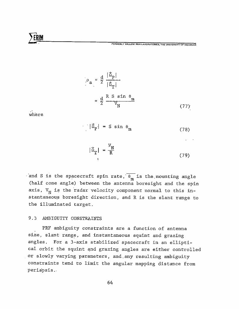
d R S sin e 2 VN (77)
where
"* = S sin e mn (78)
IQI =V R (79)
and S is the spacecraft spin rateOm is the.mounting angle
(half cone angle) between the antenna boresight and the spin
axis, VN is the radar velocity component normal to this instantaneous boresight direction, and R is the slant range to
the illuminated target.
9.3 MBIGUITY CONSTRAINTS
PRF ambiguity constraints are a function of antenna size, slant range, and instantaneous squint and grazing angles. For a 3-axis stabilized-spacecraft in an elliptical orbit the squint and grazing angles are either controlled
or slowly varying parameters, and-any resulting ambiguity
constraints tend to limit the angular mapping distance from
peridpsis.
64

FORMERLY WILLOW RUN LABORATORIES, THE UNIVERSY OF MICHIGAN
For a spinning spacecraft, the grazing angle changes
rapidly during the spin angle, and ambiguity constraints
limit the coverage during a spin cycle. The result is that mapping will then be confined to that portion of the antenna
scan which is closest to the spacecraft ground track. As a result, the operating duty cycle of the radar will be on the order of the antenna beamwidth divided by 27.
9.4 POWER REQUIREMENTS
Power requirements for a specified range resolution, SNR, wavelength, orbital parameters, and terrain backscatter
coefficients are a function of effective antenna aperture area only, as given in Eq. (50). Required antenna size is similar
for the two cases. Hence, the scanning motion of the antenna is irrelevant with regard to power requirements or SNR.
9.5 DATA PROCESSING
Continuous or line-by-line processing can be used for the 3-axis stabilized spacecraft. Batch processing is required
for the spin stabilized spacecraft. Since batch mode processing can be more efficient for coarse resolution radars,
it may be preferred even for the 3-axis stabilized space
craft in a circular orbit. Processing details for the spinning spacecraft are less conventional, and should be examined in more detail, yet no new techniques are required
that are not already in use for other coherent pulsed
Doppler radars.
65

L RIM FORMERLY WILLOW RUN LABORATORIES THE UNIVERSITY OF MICHIGAN
10 RECOMMENDED SPIN PARAMETERS
10.1 INTRODUCTION
The principle parameters affecting the coverage pattern
are the spin axis orientation at periapsis and the antenna
boresight mounting angle with respect to the spin axis.
Spin rate and antenna diameter affect swath width, resolution,
and power requirements according to previously given equations.
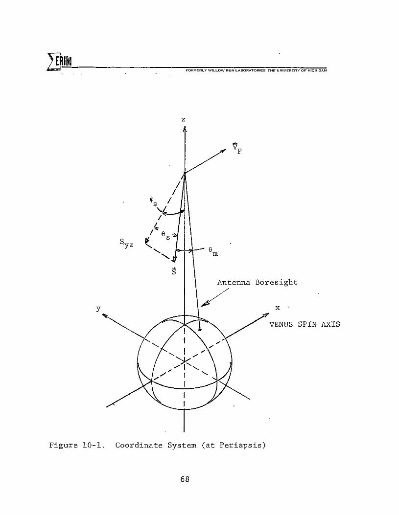
The rectangular, planet-centered, coordinate system
used in this study is shown in Figure 10-1. The positive
z-axis is in the direction of periapsis, the positive
x-axis is parallel to the spacecraft velocity vector at
p-eriapsis, and the y-axis is normal to the orbit plane.
The spin vector is defined by its magnitude, the
angle 0 between the spin vector and the orbit plane,s
and the angle 4s between the spacecraft radius vector at
periapsis and the projection of the spin vector on the
orbit plane. The angle 0s is positive when the y-compo
nent of spin is negative and is measured from the negas
tive z axis.in the clockwise direction as shown in Figure
10-1.
10.2 EFFECT OF 's
To simplify the argument, let us first consider a circular orbit. Given a fixed value of 8s, an antenna
mounting angle 0 with respect to the spin axis, andm
s, the intersection of the antenna line of sight with the
planet surface will define some track. Along this track,
67 -]EDING PAGE BLANK NOT FIPiAEl
ALE I I MFORMERLY WILLOW RUN LABORATORIES THE U NIVERSITY OF MICHIGAN
z
/ /
Syz x0
!. Antenna Boresight
x y
VENUS SPIN AXIS
Figure 10-1. Coordinate System (at Periapsis)
68

ZERIM FORMERLY WILLOW RUN LABORATORIES, THE UNIVERSITY OF MICHIGAN
the maximum grazing angle obtainable at a given position on
the orbit occurs when the antenna axis, the spin vector,
and the line from the radar to the center of the planet
are all in the same plane. The peak grazing angle over the
orbital period occurs when the component of the spin vector
in the orbit plane points toward the center of the planet.
For the case of = -0, the planet surface covered by the
track is symmetric around periapsis. Since the spin axis
is inertially fixed, the range to the mapped region will
gradually increase, the'maximum grazing angle will decrease
and the contours bounding the mapping region will diverge
as the spacecraft position departs from periapsis. Even
tually the antenna boresight will completely miss the planet.
Values of 0s other than zero will merely cause this same
track to be shifted on the planet surface. The new track
can be visualized by rotating all points of the track cor
responding to 0s = 0 through an angle 'p around the positives
y-axis in Figure 10-1. Mapping parameters at a given point
on the rotated track such as resolution, power, and so forth,
will have the same values as those of the corresponding point on the 's = 0 track. The surface coordinates of a
point on the rotated track relate to those of the corres
ponding point on the 's = 0 track by the matrix of axes
rotations through an angle 'ps around the positive y-axis.
Based on the above discussion, the choice of 'ps mainly
determines the region of coverage on the planet surface.
The shape of this region and the mapping parameters are
symmetric around the point of peak grazing angle.
The basic concept holds for elliptical orbits except
that the vehicle altitude gradually increases from periapsis
and the symmetry around the point of peak grazing angle.
ra'

FORMERLY WILLOW RUN LABORATORIES THE UNIVERSfY OF MICHIGAN
is generally destroyed (except for s = 0 where the altitude
changes symmetrically on either side of periapsis).
10.3 EFFECT OF es
The combination of es and 0m determines the maximum
grazing angle, the resolution and the shape of the antenna
trace-on the planet surface.
Neglecting the surface curvature, the peak grazing
angle realized during the orbit equals the magnitude of
the difference between 0 and 0m . This occurs when the s m
component of the spin in the orbit plane points toward the
center of the planet. The grazing angle is the single most
important parameter that-affects power requirements and
the time-bandwidth product of-the radar signal. Minimum
power requirement is realized at the peak grazing angle
because the highest radar cross section.and the minimum
range to the mapped region occur at maximum grazing angle.
The minimum time-bandwidth product also occurs at the
peak-grazing angle.
10.4 SIMULATION
A computer program was developed which calculates, the
mapping parameters, the power requirements,-and the surface
longitude and latitude of the target point for a given cir
cular antenna aperture diameter, antenna mounting angle and
a spin vector. A modified version of this program was de
veloped which calculates the same parameters at the poin.tof
maximum grazing angle for each point on the orbit during the
spin cycle.
70
RIIM FORMERLY WILLOW RUN LABORATORIES. THE UNIVERSITY OF MICHIGAN
The first version calculates the point-by-point parameters as the vehicle moves on orbit and the antenna spins around
the spin axis. The modified version calculates the same
parameters assuming the angular orientation of the antenna
has been chosen such that the antenna is currently directed
toward the maximum grazing direction at any point on orbit.
The results obtained from the modified version clarify the
effects of spin axis orientation and mounting angle on the
mapping parameters. The percentage of coverage and the degree
of overlap of the mappable region between consecutive cycles
of spin are determined from the results of the original
version.
Results of the modified simulations are given in the
next three sections. For all cases, orbit eccentricity is
0.2, periapsis altitude is 500 km, antenna diameter is 2
meters, spin rate is 5 rpm, and the slant range resolution is
50 meters. Periapsis is assumed to be located at the equator.
Azimuth resolution, time-bandwidth product and average transmitted power requirements for unity (0 dB)* SNR are plotted
as a function of target latitude. Fixed radar parameters
used for the power calculations are given in Section 5.
10.5 SPIN AXIS IN THE ORBIT PLANE
In this-configuration, the spin axis is in the orbital
plane, parallel to the planet surface at periapsis (4s =90o,
as = 00). This mode corresponds to the Pioneer Venus alti
meter experiment which uses a continuously variable antenna
mounting angle[51.
Figures 10-2 through 10-4 show resolution, time-band
*This value is convenient for scaling although a nominal 10 dB is considered necessary for adequate radar opertion.
71

CC,
C;in
C
(n
em =900
zCs
C;00
03
0
00
0.00 10.00 20.00 30.00 4O.00 50.00 60.00 70.00 80. 00 90.00 LRTITUDE IN DEGREES
Figure 10-2. Resolution for Snin Axis in thn (hi-t Piano

0
0
'C0
Ir-M
X:I-0
I-4l
f-- e=90 ° 0 75 ° 0 60 ° 45 ° 30 ° 0
15'
'0.00 10.00 20.0O0 30.0O0 40.00 50.0O0 60.0O0 70.0O0 80.O0 90.0 LATITUDE IN DEGREES
Figure 10-3. Time-Bandwidth Product for Spin Axis in the Orbit Plane.

01 0m
90 0
c_
060
,AC 0.0
750
45 °0
CD 150
¢r>cJ
C:)
C3
70.0O0 10.0O0 20.0O0 30.0O0 40.0 0 50.0O0 60.0O0 70.0O0
LRTITUDE IN DEGREES
Figure i0-4..•.Power Requirements for Spin Axis in the Orbit Plane.
80.0O0 90.0

oo Antenna Mounting Angle, ( - 900
C,In
C3)
0
0
CD
0
C4
CD
Ujm
LuJ
CDzN
uF
r-I-.-
CD -I 1
0 0
0
-
1.00 so 0.00 .50 -1.00 -1.50LONGITUDE IN DEGREES
Figure 10-5. Ground Track for Spin Axis in the Orbit Plane.
75

FORERL WLLOW RU ORATORIES ThE UNIVRSTY OF MICHIGAN
width product and power requirements for different values of the antenna mounting angle 0 . (Note that these curves reverse direction as the boresight passes over the point of maximum Latitude.) The case of 0m = 900 results in symmetrical coverage about periapsis. As the mounting angle is
decreased, higher latitudes are favored at the expense of the lower hemisphere. For a fixed antenna mounting angle, coverage is limited by ambiguity constraints (via the timebandwidth product) and power requirements. However, if the antenna mounting angle can be changed continuously during
the orbit, the resulting performance is given by the lower envelope of the curves shown in Figures 10-2 through 10-4.
Figure 10-5 shows the ground track of the antenna boresight near periapsis for a 900 mounting angle. This represents the worst case coverage for a fixed antenna
beamwidth. For the assumed 2 meter antenna, surface coverage
is approximately 0.24 degrees of latitude or longitude at periapsis and steep grazing angles. Planet rotation is approximately 0.14 degrees longitude per orbit. Hence
there is considerable cross-track overlap available if mapping is done on every orbit, but along-track coverage is inadequate. Since it does not seem practical to use successive orbits to fill the coverage gaps, this mode of operation does not seem
useful.
10.6 SPIN AXIS NORMAL TO ORBIT PLANE
In this configuration, the spin axis is normal to the orbital plane and remains parallel to the planet surface at the nadir point during the entire orbit (es = 900). Coverage and power requirements are determined by the antenna mounting angle, which determines the grazing angle at the planet
surface. 76

S RIM= FORMERLY WILLOW RUN LAORATORIES I.. UNIVERSITY OF MICHIOAN
-Figures 10-6 through 10-8 show resolution, time band
width product and power requirements for different values of
antenna mounting angle. Note that for this case, all results
are symmetric about periapsis.
Except for the fact that azimuth resolution is limited
by the target dwell time, this case corresponds to a 3-axis
stabilized spacecraft. In particular, ambiguity constraints
and power requirements are identical for the two spacecraft.
Azimuth resolution is proportional to slant range, and
hence varies only slightly with antenna mounting angle. How
ever, time-bandwidth product and power requirements are very
sensitive to grazing angle, and therefore vary significantly
over small changes in mounting angle for angles near 800
(corresponding to a sidelook angle of 100 off nadir). In
this case, improved performance might be achieved by incor
porating a small (+50) change in antenna mounting angle. This
could improve coverage by operating at a shallower grazing
angle at periapsis, and still permit adequate SNR by using a
steeper grazing angle at higher latitudes.
Coverage for an antenna mounting angle of 800 is indicated in Figure 10-9. Only the portion of the spin cycle for
which the time-bandwidth product is less than unity is shown.
In this case cross-track coverage is approximately 0.20
plus 0.240 due to antenna beamwidth, or approximately three
times the plant rotation interval per orbit. Figure 10-9
also indicates considerable overlap in the along-track
direction. Since the illuminated patch size increases away
from periapsis, this mode of operation can give complete
planet coverage.
77

0
LLJ, C
C
to
S::0 0.00 20.00 30.00 q0.O0 50.00 60.00 70.00 80.00 90.00
LATITUDE IN DEGREES
Figure 10-6. Resolution for Spin Axis Normal to the orbit Plane.

600
OD C
700
0
I0
CU.
',6O0 !0.0O0
Figure
20.0 0
0.7.
30.0O0 40. 00O 50.0O0 60.0O0 70.0O0 80.0O0
LATITUDE.IN DEGREE.FS
Time-Bandwidth Product for Spin Axis Normal to the Orbit Plane.
90. 00

00
060 00 C
0~
075
ca
r. 0 0 800
0.00 10.0O0 20.0O0 30.0O0 W.O 00 50.0O0 60.0O0 70o.00 80,.00 LATITUDE IN DEGREES
Figure 10-8. Power Requirement for Spin Axis Normal to the Orbit Plane
96. 0

Antenna Mounting Angle, 0 800C m
Co
C1) 0
•n" Lid
CD
li
I.-
._-
C3 0
0
0.00 -.50 -1.00 -1.50 -2.00 -2.50
LONGITUDE IN DEGREES Figure 10-9. Ground Track for Spin Axis Normal to the
Orbit Plane 81

EIM FORMERLY WILLOW RUN LABORATORIES THC UNIVERST OF MICHIGAN
10.7 GENERAL SPIN AXIS ORIENTATION
By orienting the spin axis just off the nadir point at
periapsis and using a small antenna mounting angle, the ground
track of the antenna boresight will trace a nominal spiral
patch near the spacecraft ground track. As the antenna
mounting angle approaches zero, the achievable azimuth reso
lution approaches half the antenna diameter. However, it is
easy to show that this mode of operation will permit mapping
only near periapsis since the grazing angle will decrease
rapidly as the spacecraft departs from periapsis. This will
quickly lead to a time-bandwidth product greater than unity
which will render the system ambiguous.
Another approach to the general case is to consider a
slight modification from mapping normal to the orbital plane.
By decreasing the angle of the spin axis from the
orbital plane, the spin component normal to the line-of
sight can be reduced, thus improving azimuth resolution.
By increasing the angle s from zero, the latitude corres
ponding to the peak grazing angle can be increased.
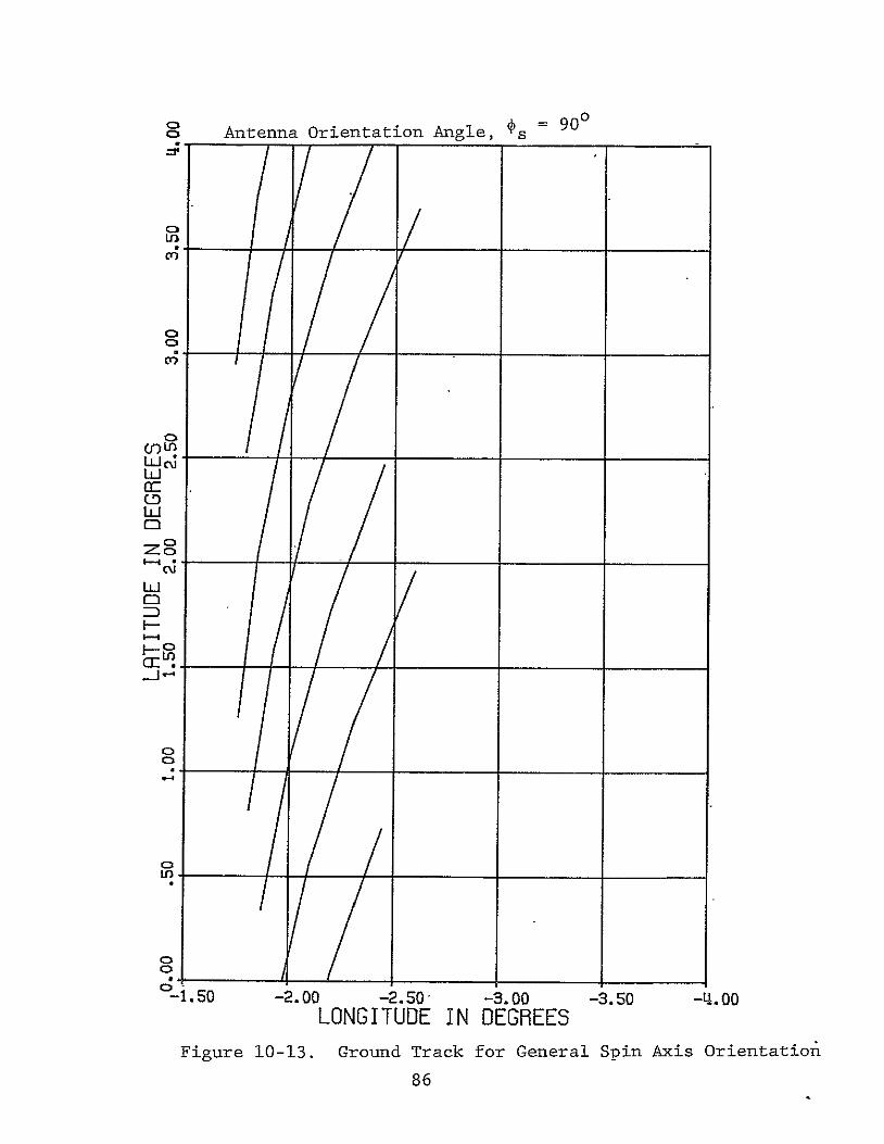
Figures 10-10 through 10-13 show results for a spin
axis 150 from the normal to the orbit plane (9s = 750 ) and
an antenna mounting angle of 650, with the orientation of
the spin axis in the orbit plane (4s) as a parameter.
As ds is increased from 00 (normal to planet surface at
periapsis), the position of the peak grazing angle travels
toward the planet pole, so does the position of minimum power
and time-bandwidth product. The antenna mounting angle is
650 from the spin axis, leaving a maximum possible grazing
angle of 100.
82

0 C
o . 750 S
= 650 m
0
I.-C;
C
cEz
C M
tA~ N 00
1 o 15 o
o 75 °
C
I-.
CDoc
C"
I 1. I p I I I p '0.00 10.00 20.00 30.00 40.00 50.00 60.00 70.00 80.00 90.00
LATITUDE IN DEGREES Figure 10-10. Resolution for General Spin Axis Orientation.

cc
C Se s =
o30
750
=50 es = 00
150 ° 0
450° 0
6
0
S C :)
zo LI
I-4
5
o
00.00 10.00 20.00
Figure 10-11.
30.00 40.00 50.00 60.00 70.00 80.00 LRTITUDE IN DEGREES
Time-Bandwidth Product for General Spin Axis Orientation
90.00

C
c es = 75
e= 65'
9Lu0 i-c mm
--co0CM
00
-
0
C
°O. O0 10.00 20.00
Figure 10-12.
So=0° thT~ough 900 =00 \ Qin 5 steps \
30.00 40.00 50.00 60.00 70.00 80.00 90.00 LRTITUDE IN DEGREES
Power Requirements for General Spin Axis Orientation
C1 Antenna Orientation Angle, s = 9 0 o
00
Ur)
1
Cr)
Lu 0
C)
I-
C
J J
-C,
o
1
C-1.50 -2.00 -2.50 -3.00 -3.50 -4.oo
LONGITUDE IN DEGREES Figure 10-13. Ground Track for General Spin Axis Orientation
86
- FORMERLY WILLOW RUN LABORATORIES THE UNIVERSITY OF MICHIGAN
Comparing these graphs to Figures 10-6 through 10-8,
we find-that on the power and time-bandwidth product plots
the curve corresponding toe = 900
and e = 800 forms the s m
envelope to the minima on the corresponding curves for
6s , 75 and e = 65° . This is expected0 since in all cases
the-maximum possible grazing angle is 800. In the case of
the spin axis normal to orbit plane the spin component in
the orbit plane is zero and there is no preferred orienta
tion, that is,the maximum possible grazing angle can be
real-ized at any point on the orbit. In contrast, when the
spin axis is not normal to the orbit plane the peak grazing
angle will occur when the component of the spin in the orbit
plane points toward the center of the planet. This condition
is met at only one point on the orbit. At other positions
the grazing angle will have a local maximum less than 800.
This coincides with the argument given above on the effect
of -as
Comparing the curves for resolution we find that some
gain is achieved when the antenna is tilted from the normal
to the orbit plane and the mounting angle is readjusted to
realize the same maximum grazing angle. This is mainly due
to the reduced component of the spin normal to the antenna
axis as discussed in Section 10.3.
Figure 10-13 shows the ground track of the antenna
bor-esight for as = 750 and s = 900. This orientation
increases the cross-track coverage, but introduces some
gaps in the along-track coverage near periapsis.
87

FORMERLY WILLOW RUN LABORATORIES THE UNIVERSITY OF MICHIGANL RIM
10.8 EFFECTS OF PARAMETER VARIATIONS
Figure 10-2 through 10-13 arebased on an antenna diam
eter of 2 meters and a spin rate of 5 rpm. Some simple
adjustments can be made for variations in these parameters.
Increasing antenna diameter by a factor, k, increases
azimuth resolution cell size by k, decreases the time-band
width product by k2"and decreases the power requirement by
k4 . Increasing the spin rate by a factor, k, increases
azimuth resolution cell size by k and leaves time-bandwidth
product and power requirements unchanged. Coverage is
affected by the corresponding changes in beamwidth and scan
rate.
10.9 CONCLUSIONS
By placing the spin axis normal to the orbital plane
and the antenna mounting angle such that the boresight is
10 to 15 degrees off nadir, complete planet coverage at
30 to 160 meter azimuth resolution is attainable. The
average transmitter power required for a SNR of 10 dB is
10-to 200 watts during a nominal 120 msec mapping interval
once per spin cycle. The average power over a 12 second
spin cycle is 0.1 to 2 watts. By allowing a small adjust
ment in antenna mounting angle during the orbit, the surface
grazing angle can be held constant at 72 to 78 degrees, thus
providing a large value of backscatter coefficient, permitting
mapping at reasonable average power levels.
88"

RIM FORMERLY WILLOW RUN LABORATORIES THE UNIVERSITY OF MICHIGAN
EXTENSIONS
11.1 POST-DETECTION INTEGRATION
Results of the previous sections apply to single-look
imagery. The mean intensity of the resulting imagery will
correspond to the actual surface cross-section; however due
to random phases of the terrain return, the variance of the image intensity will be equal to the mean, and will be inde
pendent from cell to cell. The result is the typical speckle
pattern associated with coherent imaging systems.
If excess Rf or Doppler bandwidth is available, this
speckle can be reduced by post-detection integration, in which
the additional data is noncoherently added after linear or
square law detection. This is generally refered to as
mixed integration, or multi-look processing.
By averaging N independently obtained image samples
corresponding to the same pixel, the image variance to mean
square ratio is reduced to 1/N. Independent samples are
obtained by either frequency diversity (increased RF band
width) or angle diversity (increased Doppler bandwidth).
For a spinning spacecraft, diversity may be attained by
tising overlapping images gathered on successive spin cycles.
This is a form of angle diversity.
In order to obtain an image intensity estimated with
a standard deviation equal to 10 percent of the mean, 100 independent samples must be noncoherently averaged. For the
case of a spinning spacecraft, only a few (less than 10) looks at any target area can be obtained when operating at the
best available resolution. Additional noncoherdnt integration
can be obtained only by sacrificing resolution. However, it
89

FORMERLY WILLOW RUN LABORATORIES THE UNIVERSrY OF MICHIGAN
has not been shown that the resulting decrease in image
variability offsets the loss in resolution. Hence, a minimal
amount of noncoherent integration, determined by overlapping
coverage, is likely to be attained.
11.2 STEREO
When mapping with the spin axis normal to the orbit plane,
images from successive spin cycles may have a sufficient
angular displacement to permit stereo viewing. -At periapsis,
the distance between image frames is approximately 100 km
corresponding to an angular separation of about 110 which
corresponds to normal stereo viewing angles.
90
FORMERLY WILLOW RUN LABORATORIES THC UNIVERSITY OF MICHIGAN
REFERENCES
T. }MacKay, J.S., et al., "A Preliminary Analysis of a Radar Mapping Mission to Venus," NASA TM X-2868, September '1973.
2. Friedman, L.D. and S.R. Rose, "Venus Orbital Imaging Radar (VOIR) Study, Final Report," JPL Report No. 760-89, November 1973.
3. Scofield, W. T., D. B. Cross, et al., "A Study of an -Orbital Radar Mapping Mission to Venus, Final Report," Martin-Marietta Aerospace, Denver Division, NASA CR114640, 114641, and 114642, September 1973.
4. Scofield, W. T., D.B. Cross, et al., "Venus Orbital Imaging Radar (VOIR) Technical Tradeoffs Study," Final Report, Martin-Marietta Aerospace, Denver Division, Report No. MCR-74-276, August 1974.
5. "Pioneer Venus Orbiter Scientific Instrument-Radar Mapper," Pioneer Document PC-417, NASA Ames Research Center.
6. Larson, R. W., J. S. Zelenka-and E. L. Johansen, "A Microwave Hologram Radar System," IEEE Transactions AES-8, pp. 208-217, 1972.
7. Larson, R. W., et al., "Investigation of Microwave Hologram Techniques for Application to Earth Resources," Proceedings of the Ninth International Symposium on Remote Sensing of Environment, pp. 1541-1569, 1974.
8. Bayma, R. W. and P.A. McInnes, "Aperture Size and Ambiguity Constraints for a Synthetic Aperture Radar," Proceedings of the IEEE International Radar Conference, pp. 499-504, 1975.
9. Mims, J.H. and J.L. Farrel, "Synthetic Aperture Imaging with Maneuvers," IEEE Transactions, AES-8, pp. 410-418, 1972.
10. Kirk, J.C., Jr., "A Discussion of Digital Processing in Synthetic Aperture Radar," IEEE Transactions,, AES-il, pp. 326-337, 1975.
91

FORMERLY WILLOW RUN LABORATORIE5. THE UNIVERSITY OF MICHIGAN
BIBLIOGRAPHY
Brown, W.M., "Synthetic Aperture Radar," IEEE Trans. Aerospace and Electronic Systems, vol. AES-3, pp. 217-229, March 1967.
Brown, W.M., and L.J. Procello, "An Introduction to Synthetic Aperture Theory," IEEE Spectrum, pp. 52-62, September, 1969.
Cutrona, L.J., W.E. Vivain, E.N. Leith, and G. 0. Hall,"A High-resolution Radar Combat-surveillance System,"
IRE Trans. Military Electronics, vol. MIL-5, pp. 127-131, January i96i.
Cutrona, L.J. and G.O. Hall, "A Comparison of Techniques for achieving fine azimuth resolution,'' IRE Trans. Military Electronics, vol MIL-6, pp. 119-121, April 1962
Harger, R.O. Synthetic Aperture Radar Systems Theory and Design. New York: Academic Press, 1970.
Heimiller, R.C., "Theory and Evaluation of Gain Patterns of Synthetic Arrays," IRE Trans. Military Electronics, vol. MIL-6, pp. 122-130, April 1962.
Matthews, R.E. ed, Active Microwave Workshop Reports, NASA SP-376, 1975.
McCord, H. L., "The Equivalence among Three Approaches to Deriving Synthetic Array Patterns and Analyzing Processing Techniques," IRE Trans. Military Electronics, vol. MIL-6 pp. 116-119, April 1962.
Moore, R.K. et al, Microwave Remote Sensors; Chapter 9, Manual of Remote Sensing, Volume I, Janza, F.J. ed., American Society of Photogrammetry, Fails Church, Va. 1975.
Sherwin, C.W., J.P. Rauna, and R.D. Rawcliffe, "Some early Developments in Synthetic Aperture Radar Systems," IRE Trans. Military Electronics, vol. MIL-6, pp. 111-115, April 1962.
Skolnik, M.I., ed., Radar Handbook, McGraw-Hill, 1970.
92