final report – inspection limit confirmation for upper ... · pdf filex figures 1...
TRANSCRIPT

PNNL-17763
Prepared for the U.S. Nuclear Regulatory Commission Under U.S. Department of Energy Contract DE-AC05-76RL01830
Final Report – Inspection Limit Confirmation for Upper Head Penetration Nozzle Cracking MT Anderson T Zhang(a) DL Rudland(a) GM Wilkowski(a) August 2008 __________________ (a) Engineering Mechanics Corporation of Columbus Columbus, Ohio


PNNL-17763
Final Report – Inspection Limit Confirmation for Upper Head Penetration Nozzle Cracking MT Anderson T Zhang(a) DL Rudland(a) GM Wilkowski(a) August 2008 Prepared for the U.S. Nuclear Regulatory under U.S. Department of Energy Contract DE-AC05-76RL01830 Pacific Northwest National Laboratory Richland, Washington 99352 ___________________ (a) Engineering Mechanics Corporation of Columbus Columbus, Ohio


v
Executive Summary
The ASME Code Case N-729-1 defines alternative examination requirements for the Control Rod Drive Mechanism (CRDM) upper head penetration nozzle welds. The basis for these examination requirements was developed as part of an Industry program conducted by the Materials Reliability Program (MRP) through the Electric Power Research Institute (EPRI). The results of this program were published in MRP-95 Rev. 1 and document a set of finite element weld residual stress analyses conducted on a variety of upper head penetration nozzles. The inspection zone selected by the industry was based on the stress where it was assumed that primary water stress corrosion cracking (PWSCC) would not initiate. As explained in MRP-95 Rev. 1, it has been illustrated that PWSCC does not occur in the Alloy-600 tube when the stresses are below the yield strength of that tube. Typical yield strengths at operating conditions for Alloy 600 range from 35 ksi to 65 ksi. A stress less than 20-ksi tension was chosen as a conservative range where PWSCC would not initiate.
Over the last several years, Engineering Mechanics Corporation of Columbus (Emc2) has conducted welding residual stress analyses on upper head penetration J-welds made from Alloy 182 weld metal for the U.S. Nuclear Regulatory Commission (NRC) staff. These efforts were performed as a confirmatory evaluation of the industry’s analyses conducted as part of their MRP-95 Rev. 1 effort. To this point, the analyses conducted by Emc2 have not been compared to the MRP-95 Rev. 1 results or the examination zones defined in the Code Case. Therefore, this report summarizes the past Emc2 CRDM welding analyses and investigates the regions where the welding stresses may be sufficiently high to promote stress corrosion cracking (SCC).
In all, 90 welding residual stress analyses were conducted by Emc2 and the largest distance below the weld where the stress drops below 20 ksi was 5 inches for the uphill weld of the 53-degree nozzle case. For the largest distance above the weld where stress drops below 20 ksi, the worst case was 1.5 inches above the downhill side of the 25-degree nozzle case.
The inspection zones described in both MRP-95 Rev. 1 and Code Case N-729-1 were set at 1.0 inch for nozzle angles greater than 30 degrees or 1.5 inches for nozzle angles less than 30 degrees, above the highest or below the lowest point on the weld. In all cases analyzed by Emc2 in this effort, there was only one case where the stress was above 20 ksi outside of this inspection zone. For that case, the stresses were very close to 20 ksi at the inspection zone limit and were considered acceptable.


vii
Acronyms and Abbreviations
ASME American Society for Mechanical Engineers CE Combustion Engineering CRDM control rod drive mechanism DEI Dominion Engineering EFPY effective full power years Emc2 Engineering Mechanics Corporation of Columbus EPRI Electric Power Research Institute FE finite element ICI in-core instrument ID inner diameter MRP Materials Reliability Program NRC United States Nuclear Regulatory Commission OD outer diameter ORNL Oak Ridge National Laboratory PVRUF Pressure Vessel Research User’s Facility PWSCC primary water stress corrosion cracking RPV reactor pressure vessel SCC stress corrosion cracking


ix
Contents
Executive Summary ...................................................................................................................................... v Acronyms and Abbreviations .....................................................................................................................vii 1.0 Introduction and Background ............................................................................................................... 1
1.1 Summary of Code Case N-729-1 ................................................................................................. 1 1.2 Summary of MRP-95 Rev. 1........................................................................................................ 1
2.0 Description of Emc2 CRDM Welding Analyses................................................................................... 3 2.1 Weld Geometry ............................................................................................................................ 3 2.2 Analysis Methodology and Procedure ......................................................................................... 8 2.3 Analyses Conducted................................................................................................................... 10
3.0 Emc2 CRDM Analyses Results .......................................................................................................... 12 3.1 Centerhole .................................................................................................................................. 13 3.2 25-degree Nozzle........................................................................................................................ 15 3.3 53-degree Nozzle........................................................................................................................ 18 3.4 Effect of Fillet Weld................................................................................................................... 20
4.0 Summary............................................................................................................................................. 20 5.0 References .......................................................................................................................................... 21 Appendix A Detailed Plots of Axial and Hoop Stress Along Tube OD and ID ...................................... A.1

x
Figures
1 Examination Volume for CRDM J-welds as Described in Code Case N-729-1 ............................... 2 2 RPV Head Geometry Used in the Weld Residual Stress Analysis.................................................... 4 3. Geometric and Material Details of a Nozzle Penetration Considered in the Residual Stress
Analysis ............................................................................................................................................. 5 4 Comparison of Weld Area for Actual CRDM Nozzles and Those Analyzed by MRP and
Emc2 .................................................................................................................................................. 5 5 Emc2 CRDM J-weld Geometries....................................................................................................... 7 6 Schematic of Weld Sequencing for “Weld Sequence #2”................................................................. 9 7 Illustration of Models with J-weld Fillet Shown ............................................................................. 12 8 Illustration of Highest and Lowest Weld Location ......................................................................... 13 9 20-ksi Stress Limit for Centerhole CRDM Cases ........................................................................... 15 10 20 ksi Stress Limit above Weld for the 25-degree Nozzle Case ..................................................... 17 11 20 ksi Stress Limit below Weld for the 25-degree Nozzle Case ..................................................... 17 12 20 ksi Stress Limit above Weld for the 53-degree Nozzle Case ..................................................... 19 13 20 ksi Stress Limit below Weld for the 53-degree Nozzle Case ..................................................... 19
Tables
1. Details of Plant RPV Heads Analyzed by MRP................................................................................ 6 2. Mechanical Properties for CRDM K-solution Analyses at 315°C .................................................... 7 3. Welding Residual Stress Analyses Cases Considered in this Study................................................ 11 4. Case Identification for the Centerhole Analyses ............................................................................. 14 5. Case Identification for the 25-degree Nozzle Analyses .................................................................. 16 6. Case Identification for the 53-degree Nozzle Analyses .................................................................. 18

1
1.0 Introduction and Background
Over the last several years, Engineering Mechanics Corporation of Columbus (Emc2) has conducted welding residual stress analyses on upper head penetration J-welds made from Alloy 182 weld metal for the United States Nuclear Regulatory Commission (NRC) staff. These efforts were performed as a confirmatory evaluation of the industry’s analyses conducted as part of their Materials Reliability Program (MRP)-95 Rev. 1 effort. From that industry effort, the American Society for Mechanical Engineers (ASME) developed a Code Case (N-729-1) to define alternative examination requirements for the control rod drive mechanism (CRDM) upper head penetration nozzle welds. To this point, the analyses conducted by Emc2 have not been compared to the MRP-95 Rev. 1 results or the examination zones defined in the code case. Therefore, this report presents a summary of past Emc2 CRDM welding analyses and investigates the area where the welding stresses may be sufficiently high to promote stress corrosion cracking (SCC).
1.1 Summary of Code Case N-729-1
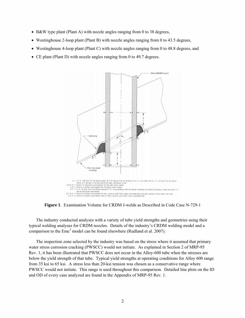
ASME Code Case N-729-1 (2006), “Alternate Examination Requirements for PWR Reactor Vessel Upper Heads With Nozzles Having Pressure-Retaining Partial-Penetration Welds,” was approved for addition into the code on March 28, 2006. A majority of this code case deals with the type of inspections to be performed, i.e., volumetric or surface, but the primary detail from this code case relevant to this study is Figure 2, which is reproduced here in Figure 1. This figure defines the distance above the highest point in the weld, and below the lowest point on the weld where the inspections have to occur; that is, the inspection zone. In this figure, this distance is denoted by the dimension “a”, which is defined as 1.5 inches for nozzle angles (θ in Figure 1) less than or equal to 30 degrees and 1.0 inch for nozzle angles greater than 30 degrees. The dimension “a” is referenced from the top of the uphill weld at the tube-head-weld triple point, and from the bottom of the downhill weld at the point where the weld crown intersects the tube outer diameter (OD). Therefore for nozzles with large incidence angles (θ), the inspection zone can be a very large distance below the uphill weld or above the downhill weld location. The code case does allow for an alternate inspection zone to be defined if additional numerical analyses are performed. Mandatory Appendix I dictates that stress analyses must be performed that illustrate that both the hoop and axial stress on the tube OD and inner diameter (ID) remain below 20 ksi outside the alternate examination zone but within the zone defined in Figure 1. Details of the required fracture analyses are given to prove that a postulated flaw in the tube would not propagate to the toe of the J-groove weld by the next inspection period for below the weld, or to critical size for a circumferential flaw in the tube above the weld. The code case also allows for a probabilistic assessment if required.
1.2 Summary of MRP-95 Rev. 1
MRP-95 Rev.1 (EPRI 2004a), “Materials Reliability Program Generic Evaluation of Examination Coverage Requirements for Reactor Pressure Vessel Head Penetration Nozzles,” was released by Electric Power Research Institute (EPRI) in September 2004. This document was the technical basis for the development of the Code Case N-729-1. It documents welding residual stress and fracture analyses that support the inspection limits used in the code case. In this report, four different plant types were investigated:
2
• B&W type plant (Plant A) with nozzle angles ranging from 0 to 38 degrees,
• Westinghouse 2-loop plant (Plant B) with nozzle angles ranging from 0 to 43.5 degrees,
• Westinghouse 4-loop plant (Plant C) with nozzle angles ranging from 0 to 48.8 degrees, and
• CE plant (Plant D) with nozzle angles ranging from 0 to 49.7 degrees.
Figure 1. Examination Volume for CRDM J-welds as Described in Code Case N-729-1
The industry conducted analyses with a variety of tube yield strengths and geometries using their typical welding analyses for CRDM nozzles. Details of the industry’s CRDM welding model and a comparison to the Emc2 model can be found elsewhere (Rudland et al. 2007).
The inspection zone selected by the industry was based on the stress where it assumed that primary water stress corrosion cracking (PWSCC) would not initiate. As explained in Section 2 of MRP-95 Rev. 1, it has been illustrated that PWSCC does not occur in the Alloy-600 tube when the stresses are below the yield strength of that tube. Typical yield strengths at operating conditions for Alloy 600 range from 35 ksi to 65 ksi. A stress less than 20-ksi tension was chosen as a conservative range where PWSCC would not initiate. This range is used throughout this comparison. Detailed line plots on the ID and OD of every case analyzed are found in the Appendix of MRP-95 Rev. 1.

3
In addition to the stress analyses results, MRP-95 Rev. 1 presents a series of fracture mechanics analyses that illustrate that if a flaw is missed outside of the inspection zone, it would not grow to an unacceptable size during the period of plant operation until the next scheduled inspection. The limiting case was for a circumferential crack above the weld at the downhill location of a 48.8 degree nozzle. This flaw had a growth time from 30 degrees to 300 degree of 9.31 effective full power years (EFPY), which is still significantly greater than the 3 year inspection interval set in MRP-117 (EPRI 2004b).
2.0 Description of Emc2 CRDM Welding Analyses
Through several NRC-funded programs, Emc2 has developed a variety of welding residual stress results for CRDM nozzle configurations. In these investigations, the variables that have been studied include:
• Nozzle location within the reactor head,
• Tube material property variations,
• Tube-to-head interference fit,
• Weld geometry,
• Number of weld passes,
• Weld sequence,
• Nozzle temperature,
• Additional manufacturing stress in tube, and
• Tube OD cold work.
The majority of the details on the welding models and their results can be found in Feng et al. (2003) and Wilkowski et al. (2007). A brief description of the welding geometry, welding procedures, and the cases included in this investigation are given in the following sections.
2.1 Weld Geometry
The reactor pressure vessel (RPV) head geometry analyzed through all of the Emc2 programs was a Westinghouse design, fabricated by Combustion Engineering for the Pressure Vessel Research User’s Facility (PVRUF) at Oak Ridge National Laboratory. This particular head design was also used in other related studies for the CRDM program at Oak Ridge National Laboratory (ORNL). Figure 2 shows the basic dimensions of the RPV head used in this study. It was taken from engineering drawings provided by ORNL.(a) The geometric features and materials surrounding the nozzle penetration are depicted in Figure 3. The RPV head, 183-mm (7.2-inch) thick, is made of SA508 Class 3 steel. On the inner surface of the steel head is a 309 stainless steel cladding layer 6.35 mm (0.25 inch) thick.(b) The CRDM tube is made of Alloy 600, with an OD of 101.6 mm (4 inches) and a thickness of 15.875 mm (0.625 inch). In (a) P. Williams, PVRUF RPV head drawing, private communication December 2001. (b) R. Bass, private communications, Oak Ridge National Laboratory, January 2002.

4
the J-weld groove, an Alloy 182 butter layer was deposited on the steel head side with a manual arc welding process and machined to 6.36-mm (0.25-inch) thick, before the groove was filled with multiple passes of Alloy 182 filler metal.
Figure 2. RPV Head Geometry Used in the Weld Residual Stress Analysis (length in mm)
By design, the outer diameter of the CRDM tube is slightly greater than the diameter of the penetration hole in the RPV head. The amount of the interference fit between the tube and the hole at room temperature varies depending on the RPV head design and manufacturer.
For many reactors, counter-bores machined from both bottom and top surfaces of the RPV head were used for nozzle locations other than the center location to ease the alignment of the tube against the penetration hole during the shrink-fitting installation step. The depth of the counter-bore is designed to be flush with the lowest point of the RPV head surface.
For these analyses, the welding geometry was developed to meet the ASME code requirements and be representative of the welds in service. According to an industry analysis (B&WOG Materials Committee 1997), an allowable weld height of 6.6 mm (0.26 in.) and a critical weld height of 3.0 mm (0.12 in.) would meet the ASME code requirements under typical reactor operating conditions. However, actual CRDM J-weld cross-section areas and heights are generally much larger (under defect-free conditions). For example, Figure 4 shows the distribution of the weld area for CRDM nozzles installed in 10 Westinghouse and B&W designed plants that were analyzed by a recent industry study (B&WOG Materials Committee 1997).
- 53 deg

5
Cladding (SS309)
Steel PVH (SA508 Class 3)
Butter Layer (Alloy 182)
Weld (Alloy 182)
Tube (IN600)
Shri
nk fi
t zon
e
t=0.25”
OD=4”
ID=2.75”
Counter bore
Cladding (SS309)
Steel PVH (SA508 Class 3)
Butter Layer (Alloy 182)
Weld (Alloy 182)
Tube (IN600)
Shri
nk fi
t zon
e
t=0.25”
OD=4”
ID=2.75”
Counter bore
Steel PVH (SA508 Class 3)
Butter Layer (Alloy 182)
Weld (Alloy 182)
Tube (IN600)
Shri
nk fi
t zon
e
t=0.25”
OD=4”
ID=2.75”
Counter bore
Figure 3. Geometric and Material Details of a Nozzle Penetration Considered in the Residual Stress
Analysis
Figure 4. Comparison of Weld Area for Actual CRDM Nozzles and Those Analyzed by MRP and Emc2

6
In addition, this figure shows the CRDM cases analyzed by the MRP (red symbols) and Emc2 (blue symbols). In this figure, the x-axis is the average weld cross-sectional area, and the y-axis is the ratio of the weld areas at the uphill and downhill locations. Clearly, the cross-section area and the height of the J-weld vary significantly from one nozzle location to another, and also vary around the circumference of a nozzle other than the center one.
For the MRP analyses (B&WOG Materials Committee 1997), the data points (red symbols in Figure 4) represent the nozzles analyzed for four characteristic plants (A–D), see Table 1. Plant B represents the largest average weld size in the group, and also had relatively high tube yield strength. Plants A and C have about average weld sizes but span the range of uphill to downhill weld size ratios, from the highest (uphill weld area almost twice that of the downhill weld) to the lowest (downhill weld area more than twice that of the uphill weld). Plant D is somewhat central to the group, both in terms of average weld size and ratio. In addition to the highest angle nozzles for each plant, the evaluation also includes selected intermediate and low angle welds from the same plant types, that is, the numbers in parentheses in Figure 4 detail the nozzle angle used in that analysis.
Table 1. Details of Plant RPV Heads Analyzed by MRP
Plant D (CE)
Plant A (B&W)
Plant B (W 2-Loop)
Plant C (W 4-Loop) CEDM ICI
Top Head ID (in.) thickness (in.)
87.27 6.626
66.3125
5.75
86 7
86
7.6875 Nozzle ID (in.) thickness (in.)
4.0
0.6175
4.0
0.625
4.0
0.625
4.05
0.661
5.563
0.4065 Total # Nozzles 69 37 96 91 10 Nozzle Angles Analyzed*
0, 18, 26, 38.5 0, 13.6, 30, 43.5 48.8 0, 7.8, 49.7 55.3
Nozzle Yield Strengths (ksi)
High: 50 Low: 37
58 63 High: 59 Low: 52.5
39.5
*Yield strengths shown here are at room temperature.
For the Emc2 analyses (blue symbols in Figure 4), geometries were chosen to span those observed in the field. For the centerhole nozzle (0 degree), weld areas of 0.4 in2, 0.56 in2 and 0.8 in2 were analyzed. For both the 25-degree and 53 degree nozzle angle cases, the weld area was approximately 0.8 in2, but the uphill and downhill areas differed as illustrated in Figure 4. In terms of yield strength, both high yield strength and low yield strength Alloy 600 tube material were used. Table 2 shows a summary of the material property results used at operating temperature.
The Emc2 weld geometries are shown in Figure 5. These models represent the base-line case for each nozzle angle. Details of the Emc2 analyses are given in the next section of this report.

7
Table 2. Mechanical Properties for CRDM K-solution Analyses at 315°C
Material Use
Elastic Modulus,
GPa Poisson’s
Ratio σy, MPa Low Yield – Alloy 600 CRDM tube 203 0.32 214.2 High Yield – Alloy 600 CRDM tube 203 0.32 321.0 SA-508 RPV head 183 0.30 268.9 Alloy 182 Weld and butter 203 0.32 162.8 SS309 Cladding 176 0.30 148.8
(a) Center hold – 0 degrees (b) Intermediate – 25 degrees
(c) Steepest side hill – 53 degrees
Figure 5. Emc2 CRDM J-weld Geometries

8
2.2 Analysis Methodology and Procedure
The details of the weld residual stress analyses for the center-hole and 53-degree nozzle models can be found in Feng et al. (2003). The details of the 25-degree nozzle model can be found in Rudland et al. (2005). Thermo-elastic-plastic finite-element (FE) simulation (using ABAQUS) was performed to simulate welding the J-weld in the CRDM nozzle. The formation of the welding residual stress was a result of the thermo-mechanical deformation process during welding. In this study, the heat flow and mechanical deformation during welding were simulated using a sequentially coupled approach (Feng et al. 1996; Wang et al. 1998; Tsai et al. 1999). In this approach, the transient heat-transfer analysis was conducted to solve the temporal and spatial distribution of the temperature in the model, and then the computed thermal history was used as thermal loading input in the subsequent mechanical analysis calculating the residual stress field. Temperature-dependent mechanical properties were utilized and isotropic hardening was assumed. The effects of melting, solidification, and annealing were simulated in the analysis. Heat transfer to the environment is assumed to occur on all free surfaces of the model. The justifications of the sequentially coupled modeling approach were provided elsewhere (Hibbitt and Marcal 1973; Mahin et al. 1991).
The welding heat flow in the tube was modeled as a heat-conduction problem. Temperature-dependent thermal conductivity and specific heat values were used. Typically, the welding arc is treated as a volumetric moving heat source, taking the double-ellipsoidal distribution proposed by Goldak et al. (1984). However, such moving source analyses can be very computationally intense (Chen et al. 2004). Therefore, different simplifying assumptions were made.
The centerhole weld residual stress analysis was conducted as an axis-symmetric analysis, which was revolved 180 degrees to obtain 3-dimensional results. This procedure produces a weld-sequencing effect as if each weld bead was deposited at one time; that is, no circumferential variation in the stresses.
For the 25-degree and 53-degree nozzles, the geometry is such that a 3-dimensional model was required. Therefore, three different assumptions were employed. First, the heat across the weld pass was applied instantaneously (i.e., the whole weld pass is laid at once). This method is referred to in this report as “Weld Sequence #3.”(a) This method effectively ignores the motion of the welding arc, allows for heat transfer radially away from the centerline of the weld path with no heat transfer ahead or behind the weld bead, and “shortens” the welding time. To do this, a uniform energy density is added to the whole weld pass in an exponential function form:
( )2 2
033 t t /TQq eVT
⎡ ⎤− −⎣ ⎦=π
(1)
Where q is the energy density (W/mm3) from the weld arc, V the total volume of the weld pass, t is a starting time, T the characteristic time of the traveling arc, inversely proportional to the welding speed, and Q is the total heat input during the time of welding. For this heat source, every material point in the weld will experience the same heat-source cycle, and hence similar temperature histories. Therefore, at
(a) The weld sequence labeling reflects the order in which the analyses were conducted (i.e., Weld Sequence #1
was the first to be completed); however, the analysis description in this report required Weld Sequence #3 to be described first.

9
any time, there is no heat flux gradient and therefore minimum temperature gradients over the entire weld pass.
Considering the highly localized heat flux and temperature gradients in actual welding processes, the uniform source approach described above might oversimplify the process. Since the actual weld metal is deposited continuously, a better approximation of the process would be to add each weld pass in sections instead of all at once. As a second consideration for this study, each weld pass is divided into three segments. For each of the three segments, the energy density distribution follows Eq. (1). For this sequence, two variations were assumed. First, the three segments were applied from the downhill to the uphill location. The sequence is referred to as “Weld Sequence #1.” Second, the three passes(a) were applied as shown in Figure 6 (i.e., side, downhill and uphill). This sequence is referred to as Weld Sequence #2.”
Figure 6. Schematic of Weld Sequencing for “Weld Sequence #2”
As mentioned, temperature-dependent material properties were used for simulating welding residual stress, including the thermophysical and mechanical properties of the materials involved in the CRDM nozzle fabrication. Great care was taken to ensure that the material properties used in the weld simulation analysis were as realistic as possible. The material properties necessary for the CRDM weld stress analysis were collected from various sources in the open literature and through data exchanges with industry. In addition, the temperature-dependent stress-strain curves for Alloy 182 weld metal [up to 1,255K (1,800°F)] and carbon steel SA-508 [up to 1,033K (1,400°F)] were experimentally determined at ORNL (Feng et al. 2003).
(a) The text describes three passes, but the figure shows four passes. In the analyses, symmetry is assumed;
therefore the four passes shown in the figure are represented by three passes in the analysis.

10
2.3 Analyses Conducted
The welding analyses conducted in the Emc2 CRDM effort consisted of nineteen (19) centerhole, five (5) 25-degree nozzle, and four (4) 53-degree nozzle analyses for a total of twenty-eight (28) welding analyses. Note there were a few other centerhole analyses, for instance at different operating temperatures, but the resulting stresses were not very different from the base case, so they are not presented here. For information purposes, the base-case centerhole solutions consisted of
• 13 weld passes
• 22.5 deg bevel angle
• 0-mil interference fit
• Low yield strength tube material
• Design pressure = 2,500 psi
• Temperature = 605°F
For the 25-degree and 53-degree Nozzle Cases, the following base-case conditions were used:
• 14 weld passes
• 0-mil interference
• Design pressure = 2,500 psi
• Temperature = 605°F
Table 3 shows the details of the analyses considered in this study and illustrates some of the variations from the base case.
As mentioned previously, the details for many of the welding residual stress cases can be found elsewhere (Feng et al. 2003; Chen et al. 2004; Rudland et al. 2005; Wilkowski et al. 2007). However, the cases in Table 3 that show a fillet weld were analyzed in the ongoing Component Integrity Program. For these analyses, fillet weld geometry was added to previously run cases for the centerhole and 25-degree nozzle geometry. The purpose of these analyses was to assess whether the addition of a fillet, which is a typical byproduct of the J-welding process that is not typically modeled, affects the stresses along the tube ID and OD. For the analyses presented in this effort, the fillet weld was idealized as triangular in shape. The dimensions of the fillet weld for each case are shown in Figure 7. These geometries were discussed and agreed upon with NRC staff.
From Table 3, the centerhole fillet analysis, Analysis 10, was a restart analysis of Analysis 9 with the addition of the fillet weld.(a) As illustrated in Figure 7, four weld beads were used to represent the fillet weld in the axis-symmetric analysis. Similarly, in the 25-degree nozzle fillet analyses, Analyses 22, 23 and 24, were restart analyses of Analysis 21. In these cases, the fillet weld was represented by one single weld bead in each analysis. Past research (Rudland et al. 2007) suggests that this lumped weld pass
(a) The analysis numbers in Table 3 do not necessarily represent the order in which the analyses were conducted.
The order of the analyses in this report was set for convenience only.

11
approach will give conservative (high) residual stresses. In all cases shown in Table 3, the design pressure of 2,500 psi and operating temperature of 605F were used.
Table 3. Welding Residual Stress Analyses Cases Considered in this Study
Analysis # Nozzle Angle,
degree # Weld Passes Notes
1 0 13 Base case 2 0 13 15 deg bevel angle 3 0 13 2 mils interference fit 4 0 13 4.5 mils interference fit 5 0 13 45 deg bevel angle 6 0 13 High yield strength tube 7 0 13 Inverse weld sequence 8 0 13 Low yield strength tube 9 0 13 Variable yield strength tube
10 0 13 Variable yield strength tube with fillet weld 11 0 13 With OD grinding stress 12 0 20 15 deg bevel angle 13 0 20 20-ksi manufacturing stress 14 0 20 22.5 deg bevel 15 0 20 45 deg bevel angle 16 0 27 15 deg bevel angle 17 0 27 22.5 deg bevel 18 0 27 45 deg bevel angle 19 0 27 9 mils interference fit 20 25 14 Weld sequence #2 21 25 14 Weld sequence #3 22 25 14 Weld sequence #3 with fillet #1 23 25 14 Weld sequence #3 with fillet #2 24 25 14 Weld sequence #3 with fillet #3 25 53 14 Weld sequence #1 26 53 14 Weld sequence #1 – high yield tube 27 53 14 Weld sequence #2 28 53 14 Weld sequence #3

12
(a) Centerhole (b) 25-degree nozzle – Fillet #1
(c) 25-degree nozzle – Fillet #2 (d) 25-degree nozzle – Fillet #3
Figure 7. Illustration of Models with J-weld Fillet Shown
3.0 Emc2 CRDM Analyses Results
For each of the analyses listed in Table 3, line plots of axial and hoop stress were generated along the tube ID and OD at the uphill, sidehill and downhill locations. These line plots can be found in Appendix A. A summary of these results is presented in this section of the report. A couple of points need to be made about the results.
• All results are presented in US Customary units since they are to be directly compared to results in MRP-95 Rev. 1 and Code Case N-729-1.
• Each analysis from Table 3 was used to generate several line plots. For the centerhole case, each analysis generated four line plots, i.e., axial and hoop stress at the tube ID and OD. For both the 25-degree and 53-degree Nozzle Cases, each analysis generated twelve line plots, i.e., axial and hoop stress at the tube ID and OD at the uphill, sidehill and downhill locations. All of the line plots are normalized to the location of the triple point for comparison purposes.
• For the comparisons, the inspection zone limit is defined as that described in Code Case N-729-1. For incident angles ≤ 30 degrees, the zone extends 1 inch above the highest uphill and 1 inch below

13
the lowest downhill location. For incident angles >30 degrees, the zone extends 1.5 inch above the highest uphill and 1.5 inch below the lowest downhill location. The definition of the highest uphill location on the weld and the lowest downhill location on the weld is shown in Figure 8. For the fillet weld cases, the lowest downhill location is at the bottom of the fillet weld.
Figure 8. Illustration of Highest and Lowest Weld Location
• The results are presented as the distance along the tube where the stress drops below 20 ksi in order to compare directly to the results described in MRP-95 Rev. 1 and Code Case N-729-1.
3.1 Centerhole
From the eighteen (18) centerhole analyses shown in Table 3, thirty-six (36) cases and line plots were generated. The description of each case is shown in Table 4. From the line plots shown in Appendix A, the distance along either the tube OD or ID where the axial and hoop stress drops below 20 ksi were extracted and are shown graphically in Figure 9. The blue line in this figure represents the inspection limit from Code Case N-729-1. In this figure, the case numbers correspond to the cases shown in Table 4. For the cases where no results are shown, the stresses dropped below 20 ksi within the weld region.
The results from Figure 9 suggest that in all but one case, the stresses in the centerhole analyses fall below 20 ksi at a distance of 1.2 inches either above or below the weld. The case that is greater is the ID hoop stress for a 13-pass weld with a high interference fit (Case 7). However, for this case, stress drops below 20 ksi only 0.2 inch before the end of the inspection zone. In addition, several cases have a slightly greater than 1 inch distance from the weld where the stress drops below 20 ksi. These are all ID hoop stress cases (Cases 3, 6, 21, 23, 29, 30, 31, and 32). For axial stress, the largest distance where the stress drops below 20 ksi is for the 13-pass weld with a 15 degree bevel (Case 8). In this case, the axial stress just reaches 20 ksi and then drops off quickly. All of the other cases are well below 20 ksi, one inch away from the weld, which is 0.5 inch from the end of the inspection zone.

14
Table 4. Case Identification for the Centerhole Analyses
Case # Nozzle Angle,
degree WRS
Location # Weld Passes Notes
1 0 ID 13 Variable yield strength tube 2 0 ID 13 Variable yield strength tube with fillet weld 3 0 ID 13 Low yield strength tube 4 0 ID 13 High yield strength tube 5 0 ID 13 Inverse weld sequence 6 0 ID 13 2 mils interference fit 7 0 ID 13 4.5 mils interference fit 8 0 ID 13 15 deg bevel angle 9 0 ID 13 45 deg bevel angle
10 0 ID 13 With OD grinding stress 11 0 OD 13 Variable yield strength tube 12 0 OD 13 Variable yield strength tube with fillet weld 13 0 OD 13 Low yield strength tube 14 0 OD 13 High yield strength tube 15 0 OD 13 Inverse weld sequence 16 0 OD 13 2 mils interference fit 17 0 OD 13 4.5 mils interference fit 18 0 OD 13 15 deg bevel angle 19 0 OD 13 45 deg bevel angle 20 0 OD 13 With OD grinding stress 21 0 ID 20 15 deg bevel angle 22 0 ID 20 22.5 deg bevel 23 0 ID 20 45 deg bevel angle 24 0 ID 20 20 ksi manufacturing stress 25 0 OD 20 15 deg bevel angle 26 0 OD 20 22.5 deg bevel 27 0 OD 20 45 deg bevel angle 28 0 OD 20 20 ksi manufacturing stress 29 0 ID 27 15 deg bevel angle 30 0 ID 27 22.5 deg bevel 31 0 ID 27 45 deg bevel angle 32 0 ID 27 9 mils interference fit 33 0 OD 27 15 deg bevel angle 34 0 OD 27 22.5 deg bevel 35 0 OD 27 45 deg bevel angle 36 0 OD 27 9 mils interference fit

15
0.00
0.20
0.40
0.60
0.80
1.00
1.20
1.40
1.60
1 2 3 4 5 6 7 8 9 10 11 12 13 14 15 16 17 18 19 20 21 22 23 24 25 26 27 28 29 30 31 32 33 34 35 36
Case Number
Dis
tanc
e st
ress
dro
ps b
elow
20k
si, i
nch Axial stress - below weld
Axial stress - above weldHoop stress - below weldHoop stress - above weldInspection zone limit
Nozzle angle = 0 degrees
Figure 9. 20-ksi Stress Limit for Centerhole CRDM Cases
3.2 25-degree Nozzle
From the five (5) 25-degree Nozzle Cases, thirty (30) cases and line plots were generated. A description of each case is given in Table 5. From the line plots in Appendix A, the distances above and below the weld where the stress drops below 20 ksi are shown graphically in Figure 10 and Figure 11, respectively. In each of these figures, the cases are segregated by location on the nozzle, i.e., uphill, sidehill or downhill. In addition, the dark blue lines on the figures represent the distance from the weld to the inspection zone limits suggested in Code Case N-729-1.
For the cases above the weld, Figure 10 suggests that the maximum distance where the stress drops below 20 ksi is about 0.7 inches below the inspection zone limit, i.e., 0.8 inches above the highest weld location on the uphill side. These cases are for Weld Sequence #3 (weld bead laid all at once), which has been shown in the past to give slightly higher welding residual stresses (Rudland et al. 2007). For these same cases, the stresses did not drop below 20 ksi until about 1.5 inches above the downhill location on the weld, which is still about 2 inches below the inspection zone limit.
Similar results are shown for below the weld as illustrated in Figure 11. Case 58, which corresponds to the downhill, hoop stress for Weld Sequence #3, gave results closest to the inspection limit; that is, the stress dropped below 20 ksi approximately 0.66 inches below the inspection limit. On the uphill side, for several of the cases, the stress did not drop below 20 ksi until over 2 inches from the bottom of the weld, but this location is about 1.5 inches below the inspection zone limit. At the sidehill location, for Case 50, which is again Weld Sequence #3, the stress dropped below 20 ksi about 1.1 inches below the weld, which corresponded to 1.46 inches below the inspection zone limit.

16
Table 5. Case Identification for the 25-degree Nozzle Analyses
Case # Nozzle Angle,
degree WRS Location # Weld Passes Notes
37 25 ID - Uphill 14 Weld sequence #2 38 25 ID - Uphill 14 Weld sequence #3 39 25 ID - Uphill 14 Weld sequence #3 with fillet #1 40 25 ID - Uphill 14 Weld sequence #3 with fillet #2 41 25 ID - Uphill 14 Weld sequence #3 with fillet #3 42 25 OD - Uphill 14 Weld sequence #2 43 25 OD - Uphill 14 Weld sequence #3 44 25 OD - Uphill 14 Weld sequence #3 with fillet #1 45 25 OD - Uphill 14 Weld sequence #3 with fillet #2 46 25 OD - Uphill 14 Weld sequence #3 with fillet #3 47 25 ID - Sidehill 14 Weld sequence #2 48 25 ID - Sidehill 14 Weld sequence #3 49 25 ID - Sidehill 14 Weld sequence #3 with fillet #1 50 25 ID - Sidehill 14 Weld sequence #3 with fillet #2 51 25 ID - Sidehill 14 Weld sequence #3 with fillet #3 52 25 OD - Sidehill 14 Weld sequence #2 53 25 OD - Sidehill 14 Weld sequence #3 54 25 OD - Sidehill 14 Weld sequence #3 with fillet #1 55 25 OD - Sidehill 14 Weld sequence #3 with fillet #2 56 25 OD - Sidehill 14 Weld sequence #3 with fillet #3 57 25 ID - Downhill 14 Weld sequence #2 58 25 ID - Downhill 14 Weld sequence #3 59 25 ID - Downhill 14 Weld sequence #3 with fillet #1 60 25 ID - Downhill 14 Weld sequence #3 with fillet #2 61 25 ID - Downhill 14 Weld sequence #3 with fillet #3 62 25 OD - Downhill 14 Weld sequence #2 63 25 OD - Downhill 14 Weld sequence #3 64 25 OD - Downhill 14 Weld sequence #3 with fillet #1 65 25 OD - Downhill 14 Weld sequence #3 with fillet #2 66 25 OD - Downhill 14 Weld sequence #3 with fillet #3

17
0.00
0.50
1.00
1.50
2.00
2.50
3.00
3.50
4.00
37 38 39 40 41 42 43 44 45 46 47 48 49 50 51 52 53 54 55 56 57 58 59 60 61 62 63 64 65 66
Case number
Dis
tanc
e ab
ove
wel
d s
tress
dro
ps b
elow
20k
si, i
nch
Axial stress - above weld Hoop stress - above weld Inspection zone limit
Nozzle angle = 25 degrees
Uphill
Sidehill
Downhill
Figure 10. 20 ksi Stress Limit above Weld for the 25-degree Nozzle Case
0.00
0.50
1.00
1.50
2.00
2.50
3.00
3.50
4.00
37 38 39 40 41 42 43 44 45 46 47 48 49 50 51 52 53 54 55 56 57 58 59 60 61 62 63 64 65 66
Case number
Dis
tanc
e be
low
wel
d st
ress
dro
ps b
elow
20k
si, i
nch
Axial stress - below weld Hoop stress - below weld Inspection zone limit
Nozzle angle = 25 degreesUphill
Sidehill
Downhill
Figure 11. 20 ksi Stress Limit below Weld for the 25-degree Nozzle Case

18
3.3 53-degree Nozzle
From the four (4) 53-degree Nozzle Cases, twenty-four (24) cases and line plots were generated. A description of each case is given in Table 6. From the line plots in Appendix A, the distances above and below the weld where the stress drops below 20 ksi are shown graphically in Figure 12 and Figure 13, respectively. In each of these figures, the cases are segregated by location on the nozzle (i.e., uphill, sidehill or downhill). In addition, the blue line again represents the distance from the weld location to the inspection zone limit described in Code Case N-749-1.
Table 6. Case Identification for the 53-degree Nozzle Analyses
Case # Nozzle Angle,
degree WRS Location # Weld Passes Notes
67 53 ID - Uphill 14 Weld sequence #1 68 53 ID - Uphill 14 Weld sequence #2 69 53 ID - Uphill 14 Weld sequence #3 70 53 ID - Uphill 14 Weld sequence #1 - high yield tube 71 53 OD - Uphill 14 Weld sequence #1 72 53 OD - Uphill 14 Weld sequence #2 73 53 OD - Uphill 14 Weld sequence #3 74 53 OD - Uphill 14 Weld sequence #1 - high yield tube 75 53 ID - Sidehill 14 Weld sequence #1 76 53 ID - Sidehill 14 Weld sequence #2 77 53 ID - Sidehill 14 Weld sequence #3 78 53 ID - Sidehill 14 Weld sequence #1 - high yield tube 79 53 OD - Sidehill 14 Weld sequence #1 80 53 OD - Sidehill 14 Weld sequence #2 81 53 OD - Sidehill 14 Weld sequence #3 82 53 OD - Sidehill 14 Weld sequence #1 - high yield tube 83 53 ID - Downhill 14 Weld sequence #1 84 53 ID - Downhill 14 Weld sequence #2 85 53 ID - Downhill 14 Weld sequence #3 86 53 ID - Downhill 14 Weld sequence #1 - high yield tube 87 53 OD - Downhill 14 Weld sequence #1 88 53 OD - Downhill 14 Weld sequence #2 89 53 OD - Downhill 14 Weld sequence #3 90 53 OD - Downhill 14 Weld sequence #1 - high yield tube

19
0.00
1.00
2.00
3.00
4.00
5.00
6.00
7.00
67 68 69 70 71 72 73 74 75 76 77 78 79 80 81 82 83 84 85 86 87 88 89 90
Case Number
Dis
tanc
e ab
ove
wel
d st
ress
dro
ps b
elow
20k
si, i
nch
Axial stress - above weld Hoop stress - above weld Inspection zone limit
Nozzle angle =53 degrees
Uphill
Sidehill
Downhill
Figure 12. 20 ksi Stress Limit above Weld for the 53-degree Nozzle Case
0.00
1.00
2.00
3.00
4.00
5.00
6.00
7.00
67 68 69 70 71 72 73 74 75 76 77 78 79 80 81 82 83 84 85 86 87 88 89 90
Case Number
Dis
tanc
e be
low
wel
d st
ress
dro
ps b
elow
20k
si, i
nch
Axial stress - below weld Hoop stress - below weld Inspection zone limit
Nozzle angle =53 degreesUphill
Sidehill
Downhill
Figure 13. 20 ksi Stress Limit below Weld for the 53-degree Nozzle Case

20
In the cases above the weld for the sidehill nozzle, the stress drops below 20 ksi at a much smaller distance as compared to the 25-degree Nozzle Case. The largest distance where the stress drops below 20 ksi comes from Case 85, Weld Sequence #3, which is 1.5 inches above the weld for both the hoop and axial stress, which corresponds to 4.8 inches below the inspection zone limit. The largest distance where the stress drops below 20 ksi for the uphill location is 0.5 inches for the axial stress of Case 74 and the hoop stress of Case 72, which both correspond to 0.5 inch below the inspection zone limit.
For the cases below the weld, the results for the 53-degree nozzle are very similar to those for the 25-degree nozzle. The largest distance where the stress drops below 20 ksi on the downhill side, was for Case 90 at about 1.2 inches, which is outside of the inspection zone by 0.2 inches. The next largest was Case 89, which was 0.3 inches below the inspection zone and corresponds to Welding Sequence #3. Clearly, the highest yield strength tube, coupled with Welding Sequence #3 would produce the largest distance from the weld where the stress drops below 20 ksi.
3.4 Effect of Fillet Weld
In this effort, a fillet weld was added to the CRDM J-weld geometry to investigate the effects of the fillet weld on the distance along the tube the stress drops below 20 ksi. Due to the finite element geometry restrictions, fillet welds were only added to the centerhole and 25-degree nozzle configurations. The geometries were shown in Figure 7. Overall, the effects of the fillet weld were minimal as illustrated in the preceding sections. Above the weld, the addition of the fillet weld did not change the distance where the stress drops below 20 ksi. Below the weld, if the bottom of the weld is defined by the lowest part of the fillet weld, the addition of the fillet weld had only a marginal effect on the distance below the weld where the stresses drop below 20 ksi. The medium sized fillet (Fillet #2) had the largest distance where the stress drops below 20 ksi. However, as noted earlier, these distances were still within the inspection zone limit described in Code Case N-729-1.
4.0 Summary
In this investigation, the CRDM welding analyses results conducted by Emc2 over the last several years for the NRC were re-evaluated to determine at what location below and above the weld the stress in the tube would drop below 20 ksi. In all, 90 cases were evaluated and the largest distance below the weld where the stress drops below 20 ksi was 5 inches for the uphill weld of the 53-degree Nozzle Case (Case 70). For above the weld, the worst case was 1.5 inches above the downhill side of the 25-degree Nozzle Case (Case 58).
The inspection zone described in both MRP-95 Rev. 1 and Code Case N-729-1 was set at 1.0 inch for nozzle angles greater than 30 degrees or 1.5 inches for nozzle angles less than 30 degrees, above the highest or below the lowest point on the weld. In all cases analyzed by Emc2 in this effort, there was only one case where the stress was above 20 ksi outside of this inspection zone. For that case, the stresses were very close to 20 ksi at the inspection zone limit and can be considered acceptable.

21
5.0 References
ASME Code Case N-721-1. 2006. Alternative Examination Requirements for PWR Reactor Vessel Upper Head with Nozzle Having Pressure-Retaining Partial-Penetration Welds, Section XI, Division 1. American Society of Mechanical Engineers, New York. B&WOG Materials Committee. 1997. Safety Evaluation for Control Rod Drive Mechanism Nozzle J-Groove Weld. Supporting Documents for RAI FRA-14, BAW-10190P. Chen Y, DL Rudland and G Wilkowski. 2004. "Impact of Welding Sequence on the CRDM Nozzle-to-Vessel Weld Stress Analysis." In Proceedings of the 2004 ASME Pressure Vessels and Piping Conference, PVP-Vol. 475, pp. 151-161. July 25-29, 2004, San Diego, CA. American Society of Mechanical Engineers, New York. EPRI. 2004a. Materials Reliability Program: Generic Evaluation of Examination Coverage Requirements for Reactor Pressure Vessel Head Penetration Nozzles, Revision 1 (MRP-95, Rev. 1). TR-1011225. Electric Power Research Institute, Palo Alto, California. EPRI. 2004b. Materials Reliability Program: Inspection Plan for Reactor Vessel Closure Head Penetrations in U.S. PWR Plants – MRP Inspection Requirements (MRP-117). EPRI Report 1007830. Electric Power Research Institute, Palo Alto, California. Draft Final Report, July 6, 2004. EPRI. 2004c. Materials Reliability Program: Reactor Vessel Closure Head Penetration Safety Assessment for U.S. PWR Plants (MRP-110). TR-1009807. Electric Power Research Institute, Palo Alto, California. Feng Z, X Wang, CR Hubbard and S Spooner. 1996. "A Finite Element Model for Residual Stress in Repair Welds." In ASME Pressure Vessel and Piping Conference, PVP-Vol. 327, pp. 119-126. American Society of Mechanical Engineers, New York. Feng Z, G Wilkowski, DL Rudland, Y-Y Wang and R Woltermann. 2003. Analysis of CRDM Nozzle-to-Vessel Weld Stresses. Engineering Mechanics Corporation of Columbus, Columbus, Ohio. For U.S. NRC, Office of Regulatory Research, March 5, 2003. Goldak mJ, A Chakravarti and M Bibby. 1984. "A new finite element model for welding heat sources." Metallurgical and Materials Transactions B 15(2):299-305. Hibbitt HD and PV Marcal. 1973. "A Numerical, Thermo-Mechanical Model for the Welding and Subsequent Loading of a Fabricated Structure." Computers & Structures 3:1145-174. Mahin KW, W Winters, TM Holden, RR Hosbons and SR MacEwen. 1991. "Prediction and Measurement of Residual Elastic Strain Distributions in Gas Tungsten Arc Welds." Welding Journal 70:245s-260s.

22
Rudland DL, Y Chen, Y-Y Wang and G Wilkowski. 2005. Comparison of Circumferential Through-Wall Cracked CRDM K-Solutions – Center-hole, Intermediate, and Steepest Side-hill Locations. Engineering Mechanics Corporation of Columbus, Columbus, Ohio. For U.S. NRC, Office of Regulatory Research. Rudland DL, Y Chen, T Zhang, G Wilkowski, J Broussard and G White. 2007. "Comparison of Welding Residual Stress Solutions for Control Rod Drive Mechanism Nozzles." In 2007 Proceedings of the ASME Pressure Vessels and Piping Conference, July 22-26, 2007, San Antonio, Texas. American Society of Mechanical Engineers, New York. Paper 2007-26045. Tsai CL, SC Park and W Cheng. 1999. "Welding Distortion of a Thin-Plate Panel Structure." Welding Journal 78(5):156s-165s. Wang YY, Z Feng and W Cheng. 1998. "Residual stress effects on crack driving force in multipass welds." In Pressure Vessel and Piping Conference; Fatigue, Fracture, and Residual Stresses, PVP-Vol. 373, pp. 469-482. San Diego, CA. American Society of Mechanical Engineers, New York. Wilkowski G, DL Rudland, Y Chen, D-J Shim, T Zhang, W Cheng, P Krishnaswamy and Y-Y Wang. 2007. Phase II – Alloy 600 Cracking. Engineering Mechanics Corporation of Columbus, Columbus, Ohio. For U.S. NRC, Office of Regulatory Research.

Appendix A
Detailed Plots of Axial and Hoop Stress Along Tube OD and ID


A.1
Appendix A
Detailed Plots of Axial and Hoop Stress Along Tube OD and ID
A.1 Centerhole Nozzle
-20
0
20
40
60
80
100
120
-2 -1.5 -1 -0.5 0 0.5 1Vertical distance on tube OD from triple point, inch
Axi
al s
tres
s, k
si
Variable tube yield strengthLow tube yield strengthInterference fir = 2milsInterference fit = 4.5milsInverse weld sequenceHigh tube yield strength15 deg bevel angleAdditional OD surface stress45 deg bevel angleWeld bottomVariable tube yield strength - FilletFillet Bottom
13 pass centerhole
Figure A.1. Axial Stress Along the Tube OD for the Centerhole Nozzle Case (13 passes)

A.2
-40
-30
-20
-10
0
10
20
30
40
-2 -1.5 -1 -0.5 0 0.5 1Vertical distance on tube OD from triple point, inch
Axi
al s
tres
s, k
siManufacturing stress 20ksi hoop
15 deg bevel angle
22.5 deg bevel angle
45 deg bevel angle
Weld Bottom
20pass centerhole
Figure A.2. Axial Stress Along the Tube OD for the Centerhole Nozzle Case (20 passes)
-40
-30
-20
-10
0
10
20
30
40
50
60
-2 -1.5 -1 -0.5 0 0.5 1Vertical distance on the tube OD from triple point, inch
Axi
al s
tres
s, k
si
15 deg bevel angle
22.5 deg bevel angle
45 deg bevel angle
Interference fit = 9 mils
Weld Bottom
27 pass Centerhole
Figure A.3. Axial Stress Along the Tube OD for the Centerhole Nozzle Case (27 passes)

A.3
-60
-40
-20
0
20
40
60
-2 -1.5 -1 -0.5 0 0.5 1
Vertical distance on the ID from the triple Point, inch
Axi
al s
tres
s, k
siVariable tube yield strengthLow tube yield strengthInterference fit= 2milsInterference fit = 4.5milsInverse weld sequenceHigh tube yield strength15 deg bevel angleAdditional OD surface stress45 deg bevel angleWeld BottomVariable tube yield strength - FilletFillet Bottom
13 pass Centerhole
Figure A.4. Axial Stress Along the Tube ID for the Centerhole Nozzle Case (13 passes)
-40
-30
-20
-10
0
10
20
30
40
-2 -1.5 -1 -0.5 0 0.5 1Vertical distance on the ID from the triple point, inch
Axi
al s
tres
s, k
si
Manufacturing stress (20ksi hoop)
15 deg bevel angle
22.5 deg bevel angle
45 deg bevel angle
Weld Bottom
20 pass Centerhole
Figure A.5. Axial Stress Along the Tube ID for the Centerhole Nozzle Case (20 passes)

A.4
-40
-30
-20
-10
0
10
20
30
40
-2 -1.5 -1 -0.5 0 0.5 1Vertical distance on the ID from the triple point, inch
Axi
al s
tres
s, k
si
15 deg bevel angle
22.5 deg bevel angle
45 deg bevel angle
9 mils interference fit
Weld Bottom
27 pass centerhole
Figure A.6. Axial Stress Along the Tube ID for the Centerhole Nozzle Case (27 passes)
-20
0
20
40
60
80
100
120
140
160
180
-2 -1.5 -1 -0.5 0 0.5 1Vertical distance on tube OD from triple point, inch
Hoo
p st
ress
, ksi
Variable tube yield strengthLow tube yield strengthInterference fit = 2milsInterference fit = 4.5milsReverse weld sequenceHigh tube yield strength15 deg bevel angleAdditional OD surface stress45 deg bevel angleWeld BottomVariable tube yield strength - FilletFillet Bottom
13 pass centerhole
Figure A.7. Hoop Stress Along the Tube OD for the Centerhole Nozzle Case (13 passes)

A.5
-40
-20
0
20
40
60
80
100
120
-2.5 -2 -1.5 -1 -0.5 0 0.5 1Vertical distance on tube OD from triple point, inch
Hoo
p st
ress
, ksi
Manufacturing stress 20 ksi hoop
15 deg bevel angle
22.5 deg bevel angle
45 deg bevel angle
Weld Bottom
20 pass centerhole
Figure A.8. Hoop Stress Along the Tube OD for the Centerhole Nozzle Case (20 passes)
-40
-20
0
20
40
60
80
100
120
-2 -1.5 -1 -0.5 0 0.5 1
Vertical distance on tube OD from triple point, inch
Hoo
p st
ress
, ksi
15 deg bevel angle
22.5 deg bevel angle
45 deg bevel angle
Interference fit = 9mils
Weld Bottom
27 pass centerhole
Figure A.9. Hoop Stress Along the Tube OD for the Centerhole Nozzle Case (27 passes)

A.6
-20
-10
0
10
20
30
40
50
60
70
-2 -1.5 -1 -0.5 0 0.5 1Vertical distance on tube ID from triple point, inch
Hoo
p st
ress
, ksi
Variable tube yield strengthLow tube yield strengthInterference fit = 2milsInterference fit = 4.5milsReverse weld sequenceHigh tube yield strength15 deg bevel angleAdditional OD surface stress45 deg bevel angleWeld BottomVariable tube yield strength - FilletFillet Bottom
13 pass centerhole
Figure A.10. Hoop Stress Along the Tube ID for the Centerhole Nozzle Case (13 passes)
-10
-5
0
5
10
15
20
25
30
35
40
-2.5 -2 -1.5 -1 -0.5 0 0.5 1Vertical distance on the tube ID from triple point, inch
Hoo
p st
ress
, ksi
Manufacturing stress 20 ksi hoop15 deg bevel angle22.5 deg bevel angle45 deg bevel angleWeld Bottom
20 pass centerhole
Figure A.11. Hoop Stress Along the Tube ID for the Centerhole Nozzle Case (20 passes)

A.7
-10
-5
0
5
10
15
20
25
30
35
40
-2.5 -2 -1.5 -1 -0.5 0 0.5 1Vertical distance on the tube ID from triple point, inch
Hoo
p st
ress
, ksi
15 deg bevel angle22.5 deg bevel angle45 deg bevel angleInterference fit = 9milsWeld Bottom
27 pass centerhole
Figure A.12. Hoop Stress Along the Tube ID for the Centerhole Nozzle Case (27 passes)
A.2 25-degree Nozzle
-60
-40
-20
0
20
40
60
80
-6 -5 -4 -3 -2 -1 0 1 2
Vertical distance along tube OD from triple point, inch
Axi
al s
tres
s, k
si
Weld sequence #2Weld sequence #3weld bottomWeld sequence #3 - Fillet #1Fillet Bottom #1Weld sequence #3 - Fillet #2Fillet Bottom #2Weld sequence #3 - Fillet #3Fillet Bottom #3
25 degree nozzle - Uphill
Figure A.13. Axial Stress Along the Tube OD for the 25-degree Nozzle Case (uphill)

A.8
-40
-20
0
20
40
60
80
100
-6 -5 -4 -3 -2 -1 0 1 2
Vertical distance along tube ID from triple point, inch
Axi
al s
tres
s, k
siWeld sequence #2Weld sequence #3Weld BottomWeld sequence #3 - Fillet #1Fillet Bottom #1Weld sequence #3 - Fillet #2Fillet Bottom #2Weld sequence #3 - Fillet #3Fillet Bottom #3
25 degree nozzle - Uphill
Figure A.14. Axial Stress Along the Tube ID for the 25-degree Nozzle Case (uphill)
-20
0
20
40
60
80
100
120
-6 -4 -2 0 2 4
Vertical distance along tube OD from triple point, inch
Hoo
p st
ress
, ksi
Weld sequence #2Weld sequence #3weld bottomWeld sequence #3 - Fillet #1Fillet Bottom #1Weld sequence #3 - Fillet #2Fillet Bottom #2Weld sequence #3 - Fillet #3Fillet Bottom #3
25 degree nozzle - Uphill
Figure A.15. Hoop Stress Along the Tube OD for the 25-degree Nozzle Case (uphill)

A.9
-20
0
20
40
60
80
-6 -5 -4 -3 -2 -1 0 1 2
Vertical distance along tube ID from triple point, inch
Hoo
p st
ress
, ksi
Weld sequence #2Weld sequence #3Weld BottomWeld sequence #3 - Fillet #1Fillet Bottom #1Weld sequence #3 - Fillet #2Fillet Bottom #2Weld sequence #3 - Fillet #3Fillet Bottom #3
25 degree nozzle - Uphill
Figure A.16. Hoop Stress Along the Tube ID for the 25-degree Nozzle Case (uphill)
-60
-40
-20
0
20
40
60
80
-6 -5 -4 -3 -2 -1 0 1 2
Vertical distance along tube OD from triple point, inch
Axi
al s
tres
s, k
si
Weld sequence #2Weld sequence #3Weld BottomWeld sequence #3 - Fillet #1Fillet Bottom #1Weld sequence #3 - Fillet #2Fillet Bottom #2Weld sequence #3 - Fillet #3Fillet Bottom #3
25 degree nozzle - Downhill
Figure A.17. Axial Stress Along the Tube OD for the 25-degree Nozzle Case (downhill)

A.10
-60
-40
-20
0
20
40
-5 -4 -3 -2 -1 0 1 2 3
Vertical distance along tube ID from triple point, inch
Axi
al s
tres
s, k
si
Weld sequence #2Weld sequence #3Weld BottomWeld sequence #3 - Fillet #1Fillet Bottom #1Weld sequence #3 - Fillet #2Fillet Bottom #2Weld sequence #3 - Fillet #3Fillet Bottom #3
25 degree nozzle - Downhill
Figure A.18. Axial Stress Along the Tube ID for the 25-degree Nozzle Case (downhill)
-20
0
20
40
60
80
100
-5 -4 -3 -2 -1 0 1 2
Vertical distance along tube OD from triple point, inch
Hoo
p st
ress
, ksi
Weld sequence #2Weld sequence #3Weld BottomWeld sequence #3 - Fillet #1Fillet Bottom #1Weld sequence #3 - Fillet #2Fillet Bottom #2Weld sequence #3 - Fillet #3Fillet Bottom #3
25 degree nozzle - Downhill
Figure A.19. Hoop Stress Along the Tube OD for the 25-degree Nozzle Case (downhill)

A.11
-40
-20
0
20
40
60
80
100
120
-6 -5 -4 -3 -2 -1 0 1 2
Vertical distance along tube ID from triple point, inch
Hoo
p st
ress
, ksi
Weld sequence #2Weld sequence #3Weld BottomWeld sequence #3 - Fillet #1Fillet Bottom #1Weld sequence #3 - Fillet #2Fillet Bottom #2Weld sequence #3 - Fillet #3Fillet Bottom #3
25 degree nozzle - Downhill
Figure A.20. Hoop Stress Along the Tube ID for the 25-degree Nozzle Case (downhill)
-40
-20
0
20
40
60
80
-6 -5 -4 -3 -2 -1 0 1 2
Vertical distance along tube OD from triple point, inch
Axi
al s
tres
s, k
si
Weld sequence #2Weld sequence #3Weld bottomWeld sequence #3 - Fillet #1Fillet Bottom #1Weld sequence #3 - Fillet #2Fillet Bottom #2Weld sequence #3 - Fillet #3Fillet Bottom #3
25 degree nozzle - sidehill
Figure A.21. Axial Stress Along the Tube OD for the 25-degree Nozzle Case (sidehill)

A.12
-80
-60
-40
-20
0
20
40
-6 -5 -4 -3 -2 -1 0 1 2
Vertical distance along tube ID from triple point, inch
Axi
al s
tres
s, k
si
Weld sequence #2Weld sequence #3Weld bottomWeld sequence #3 - Fillet #1Fillet Bottom #1Weld sequence #3 - Fillet #2Fillet Bottom #2Weld sequence #3 - Fillet #3Fillet Bottom #3
25 degree nozzle - sidehill
Figure A.22. Axial Stress Along the Tube ID for the 25-degree Nozzle Case (sidehill)
-40
-20
0
20
40
60
80
100
-6 -5 -4 -3 -2 -1 0 1 2
Vertical distance along tube OD from triple point, inch
Hoo
p st
ress
, ksi
Weld sequence #2Weld sequence #3Weld bottomWeld sequence #3 - Fillet #1Fillet Bottom #1Weld sequence #3 - Fillet #2Fillet Bottom #2Weld sequence #3 - Fillet #3Fillet Bottom #3
25 degree nozzle - sidehill
Figure A.23. Hoop Stress Along the Tube OD for the 25-degree Nozzle Case (sidehill)

A.13
-40
-20
0
20
40
60
80
-6 -5 -4 -3 -2 -1 0 1 2
Vertical distance along tube ID from triple point, inch
Hoo
p st
ress
, ksi
Weld sequence #2Weld sequence #3Weld bottomWeld sequence #3 - Fillet #1Fillet Bottom #1Weld sequence #3 - Fillet #2Fillet Bottom #2Weld sequence #3 - Fillet #3Fillet Bottom #3
25 degree nozzle - sidehill
Figure A.24. Hoop Stress Along the Tube ID for the 25-degree Nozzle Case (sidehill)
A.3 53-degree Nozzle
0
10
20
30
40
50
60
70
80
90
100
-3 -2 -1 0 1 2
Vertical distance along tube OD from triple point, inch
Axi
al s
tress
, ksi
Low yield - Weld Sequence #1Low yield - Weld Sequence #2Low yield - Weld Sequence #3High yield - Weld Sequence #1Weld bottom
53 degree nozzle - Uphill
Figure A.25. Axial Stress Along the Tube OD for the 53-degree Nozzle Case (uphill)

A.14
0
5
10
15
20
25
30
35
40
45
50
-8 -7 -6 -5 -4 -3 -2 -1 0 1 2 3
Vertical distance along tube ID from triple point, inch
Axi
al s
tres
s, k
siLow yield - Weld Sequence #1Low yield - Weld Sequence #2Low yield - Weld Sequence #3High yield - Weld Sequence #1Weld bottom
53 degree nozzle - Uphill
Figure A.26. Axial Stress Along the Tube ID for the 53-degree Nozzle Case (uphill)
-20
0
20
40
60
80
100
120
140
-3 -2 -1 0 1 2
Vertical distance along tube OD from triple point, inch
Hoo
p st
ress
, ksi
Low yield - Weld Sequence #1Low yield - Weld Sequence #2Low yield - Weld Sequence #3High yield - Weld Sequence #1Weld bottom
53 degree nozzle - Uphill
Figure A.27. Hoop Stress Along the Tube OD for the 53-degree Nozzle Case (uphill)

A.15
-100
102030405060708090
-8 -7 -6 -5 -4 -3 -2 -1 0 1 2
Vertical distance along tube ID from triple Point, inch
Hoo
p st
ress
, ksi
Low yield - Weld Sequence #1Low yield - Weld Sequence #2Low yield - Weld Sequence #3High yield - Weld Sequence #1Weld Bottom
53 degree nozzle - Uphill
Figure A.28. Hoop Stress Along the Tube ID for the 53-degree Nozzle Case (uphill)
-60
-40
-20
0
20
40
60
80
100
-3 -2 -1 0 1 2
Vertical distance along tube OD from triple point , inch
Axi
al s
tres
s, k
si
Low yield - Weld Sequence #1Low yield - Weld Sequence #2Low yield - Weld Sequence #3High yield - Weld Sequence #1Weld bottom
53 degree nozzle - Downhill
Figure A.29. Axial Stress Along the Tube OD for the 53-degree Nozzle Case (downhill)

A.16
-60
-40
-20
0
20
40
60
80
100
-3 -2 -1 0 1 2
Vertical distance along tube ID from triple point, inch
Axi
al s
tres
s, k
siLow yield - Weld Sequence #1
Low yield - Weld Sequence #2
Low yield - Weld Sequence #3
High yield - Weld Sequence #1
Weld Bottom
53 degree nozzle - Downhill
Figure A.30. Axial Stress Along the Tube ID for the 53-degree Nozzle Case (downhill)
-40
-20
0
20
40
60
80
100
120
140
-4 -3 -2 -1 0 1 2
Vertical distance along tube OD from triple point, inch
Hoo
p st
ress
, ksi
Low yield - Weld Sequence #1Low yield - Weld Sequence #2Low yield - Weld Sequence #3High yield - Weld Sequence #1Weld Bottom
53 degree nozzle - Downhill
Figure A.31. Hoop Stress Along the Tube OD for the 53-degree Nozzle Case (downhill)

A.17
-40
-20
0
20
40
60
80
100
-2 -1 0 1 2 3
Vertical distance along tube ID from triple point, inch
Hoo
p st
ress
, ksi
Low yield - Weld Sequence #1Low yield - Weld Sequence #2Low yield - Weld Sequence #3High yield - Weld Sequence #1Weld Bottom
53 degree nozzle - Downhill
Figure A.32. Hoop Stress Along the Tube ID for the 53-degree Nozzle Case (downhill)
-20
0
20
40
60
80
100
-4 -3 -2 -1 0 1 2
Vertical distance along tube OD from triple point, inch
Axi
al s
tres
s, k
si
Low yield - Weld Sequence #1Low yield - Weld Sequence #2Low yield - Weld Sequence #3High yield - Weld Sequence #1Weld Bottom
53 degree nozzle - sidehill
Figure A.33. Axial Stress Along the Tube OD for the 53-degree Nozzle Case (sidehill)

A.18
-30
-20
-10
0
10
20
-4 -3 -2 -1 0 1 2
Vertical distance along tube ID from triple point, inch
Axi
al s
tres
s, k
siLow yield - Weld Sequence #1Low yield - Weld Sequence #2Low yield - Weld Sequence #3High yield - Weld Sequence #1Weld Bottom
53 degree nozzle - sidehill
Figure A.34. Axial Stress Along the Tube ID for the 53-degree Nozzle Case (sidehill)
-20
0
20
40
60
80
-4 -3 -2 -1 0 1 2
Vertical distance along tube OD from triple point, inch
Hoo
p st
ress
, ksi
Low yield - Weld Sequence #1Low yield - Weld Sequence #2Low yield - Weld Sequence #3High yield - Weld Sequence #1Weld Bottom
53 degree nozzle - sidehill
Figure A.35. Hoop Stress Along the Tube OD for the 53-degree Nozzle Case (sidehill)

A.19
-60
-40
-20
0
20
40
-4 -3 -2 -1 0 1 2
Vertical distance along tube ID from triple point, inch
Hoo
p st
ress
, ksi
Low yield - Weld Sequence #1Low yield - Weld Sequence #2Low yield - Weld Sequence #3High yield - Weld Sequence #1Weld Bottom
53 degree nozzle - sidehill
Figure A.36. Hoop Stress Along the Tube ID for the 53-degree Nozzle Case (sidehill)
