final report nasa langley on the project entitled a low
TRANSCRIPT
FINAL REPORT
tO
NASA LANGLEY
on the project entitled
A LOW LOSS MICROSTRIP ANTENNA FOR RADIOMETRICAPPLICATIONS
submitted by
DR. PARVEEN WAHID
Electrical Engineering Department
Univerity Of Central Florida
Orlando, Florida 32186
May 2000

ABSTRACT
The design and analysis of a series-fed, low-loss, inverted microstrip array
antenna, operating at 1.413 GHz is presented. The antenna is composed of two subarrays.
Each subarray consists of an equal number of microstrip patches all connected together
with microstrip lines. In the first design microstrip array for linear polarization is
presented which incorporated a series feeding technique. The next design, which is
capable of dual linear polarization (V-polarization and H-polarization), utilizes a
corporate feed network for the V-pol and series feed arrangement for the H-pol. The first
element of each subarray for H-pol is coaxially fed with a 180 ° phase difference. This
approach ensures a symmetric radiation pattern on broadside in H-pol. For the V-pol two
feeds are in the same phase on the two subarrays ensuring a broadside beam in V-pol.
The designs presented here are simulated using the IE3D code that utilizes the method of
moments. Measured results are compared with simulated results and show good
agreement.

CHAPTER 1
INTRODUCTION
Microstrip antennas have been evolved tremendously over the last two decades
and come into play every time there is a need for low profile radiators. A microstrip
antenna has some certain distinct features such as conformability, compactness, and light
weight which are advantages over other antennas. In this project the objective is to design
a microstrip antenna array to meet specific radiometer system requirements for the
Hydrostar Spacecraft. A radiometric antenna used in remote sensing has to meet some
basic requirements such as (i) a narrow beamwidth (ii) low side lobes in all planes to
reduce the reception of spurious signals from targets outside the main beam and (iii) very
low radiation losses in order to maintain a desired radiometric resolution [1,2].
A series fed array for single linear polarization is first investigated. Next a dual
polarized microstrip antenna array is designed. The inverted microstrip configuration was
chosen for the designs because this configuration provides less dispersion and dielectric
losses than the conventional microstrip antenna configuration [3].
The series fed configuration for the antenna array with single linear polarization is
employed to reduce radiation losses. A series configuration minimizes the path length
between the elements and thus minimizes ohmic losses [4]. For radiometric applications
this reduction of losses makes the series configuration very attractive. The dual polarized
microstrip antenna array utilizes both series and corporate feeding technique to achieve
the dual polarization. The antenna has series feeding for H-pol (Horizontal Polarization)
and corporate feeding for V-pol (Vertical Polarization).

An antennacomposedof two subarraysis designedwith eachsubarrayconsisting
of anequalnumberof microstrippatchesconnectedtogetherwith microstriplines.
Microstrip antennason substratesof high dielectric constantsuffer from very
narrowbandwidth(lessthan0.5%), low efficiency,andpoor radiationpatterndue to the
presenceof unwantedsurfacewaves[5]. To reducetheseeffects,Rohacell,a substrate
with a very small dielectric constant,1.08,wasusedalongwith a superstateof dielectric
constant 3.0 (RO3003) to form an inverted antenna. The designs presented are
accomplishedusingtheIE3D code[6],which utilizesthemethodof moments.In Chapter
2, the design procedure of the microstrip antenna array for linear polarization is
presented. Chapter 3 describes the design of a dual polarized microstrip antenna array.
All experimental and simulated data for the antennas are presented and discussed.

CHAPTER 2
2.0 Design Goals
The microstrip antenna array had to be designed for a frequency of 1.413 GHz.
The antenna had to have low loss for radiometric applications and be foldable to allow
for transportation into space. The antenna array had to be capable of having dual linear
polarization, a radiation pattern with a highly directive beam and side lobe levels below
15 dB. The total length could be around 8-10 feet.
2.1 Foldable linearly polarized microstrip array: Design !
The configuration in Figure 1 shows one of the subarrays that make up the
antenna. It was designed using the software package IE3D for producing highly directive
beam on broadside. The patches are tapered in size in order to obtain a low side lobe level
and high directivity.
Figure 1: A subarray with 8 elements

In this design, the array has uniform excitation and has straight sectionsof
transmissionlinesbetweentheelements.In eachsubarraypatchesvary in dimensionsata
uniform ratio to producea very low beamwidth.The antennais centerfed at two points
(onefor eachhalf of thearray)with a 1800phasedifferencebetweenthetwo subarrays.
2.2Selection of substrate
The radiation efficiency of the antenna is determined primarily by the substrate
permittivity and thickness [7]. In all the designs presented Rohacell foam with a
permittivity of 1.08, with the commercially available thickness of 12.7mm was used as
the substrate. The microstrip antenna was etched on RT duroid material RO 3003 made
by Rogers Corporation with a permittivity of 3.0 and then inverted on to the Rohacell to
form an inverted antenna. This configuration results in reduced dielectric losses.
2.3 Design of the single element
The geometry of the single inverted patch is shown in Figure 2.
Inverted
Die eczric Patch
T
Rohacell foam
Ground Plane
Figure 2: A single inverted patch antenna

The resonantlength of a singlepatchmicrostrip antennacanbe calculatedfrom
the formulaasgivenbelow, [2,8]:
1 =CX(I_2.VR X(2.FR.._o)-'-2"A_
Where,A1= capacitivecutbackfactor
A1=0.412h x(% +0.3)(w/h -0.2674) x(_ -0.258)-l(w/h +0.8)-I
c = speedof light, Fa = patch resonantfrequency, VR = variation in resonant
frequency, _eo= effectivedielectric constantof thepatchwithout dielectric cover, 1 =
patchlength, w = patchwidth, andh = substratethickness.
Width of thepatchis givenby theformula,
w =c x(2.F R)-I x[(e r +1)/2] -,/2
The effective dielectric constant of a dielectric covered patch antenna is given by [8]:
% = Cd/C o
Where, Co = capacitance/unit length without dielectric layer present, and
Ca = capacitance/unit length with dielectric layer present.
The capacitance per unit length of the dielectric-covered microstrip lines can be
found using,
't I 1;2Ir -lXtanh '111 _ 1.6 _ e,._ c,._ + tanh(_-) <.z coth(,B) drC 4;rgo (_h) (_h)
Where [3 is the Fourier transform variable, _o is the permittivity of free space and d is
the height of the superstrate.

The lengthof singlepatchobtainedfrom the aboveempirical formula is 104mm
andthewidth of thepatchis 87.1mm. Thelengthandwidth of thepatchthusobtainedis
optimizedusingIE3D to matcha 50f2coaxial feed.This patchservesasthe first (feed)
elementin eachsubarray.
2.4Design procedure for the sixteen element array
The single patch described above is the first element of each of the eight element
subarray and is fed with a coaxial probe. The dimension of the element as obtained for a
50f2 match is L--92.65 mm and W=84.9 mm. The other elements of the array have
widths that decrease with a uniform ratio and are connected to each other by a half
wavelength microstrip line. The final design of the two subarrays with decreasing patches
is shown in Figure 3. The total length of the array is approximately 9.6 feet.
Figure 3: The two subarrays forming the 16 element array
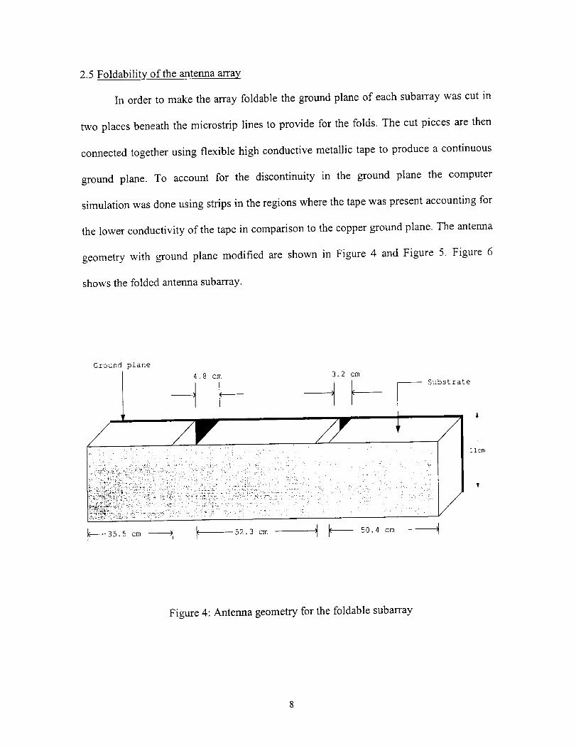
2.5 Foldability of the antenna array
In order to make the array foldable the ground plane of each subarray was cut in
two places beneath the microstrip lines to provide for the folds. The cut pieces are then
connected together using flexible high conductive metallic tape to produce a continuous
ground plane. To account for the discontinuity in the ground plane the computer
simulation was done using strips in the regions where the tape was present accounting for
the lower conductivity of the tape in comparison to the copper ground plane. The antenna
geometry with ground plane modified are shown in Figure 4 and Figure 5. Figure 6
shows the folded antenna subarray.
Ground plane
4.8 cm 3.2 cmSubstrate
Figure 4: Antenna geometry for the foldable subarray

4.8cm--_
4- 35.5cm ....
i
3.2cm-,!
1 i
,_ -- - 52.3 cm ..... _ _
50.4 cm-
--Feed Point Ground plane breaks --
Figure 5: A subarray showing the location of the cuts in the ground plane
L 52.3 cm
4.8 cm
50.4cm.
ii.0
35.5 cm fi
Figure 6: Folded antenna subarray
;round Plane

2.6 Simulated and Measured Results
The gain of the antenna under test is given by:
G, est = Ptes' .Gref
Prel
or, Gtest(dB) = G, ef(dB) + Pt_,t(dB) - P_ef(dB)
The calculated gain of the antennas is given below,
Standard gain horn received power, Pref = -25.0 dBm
Test antenna received power, Ptest
Gain of the standard horn, Gref
= -27.15 dBm
- 16.73 dB
Gain of the of the antenna in H-polarization is,
Gtest = -27.15 + 25.0 +16.73 = 14.58 dB
Simulated directivity of the antenna for H-pol = 17.2 dB
Efficiency of the antenna = 14.58 - 17.2 -- -2.62 dB
= 54.70%
Measured input impedance of each subarray was = 62.0 f2.
The simulated input impedance was = 95.0
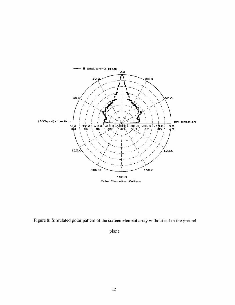
The simulated 2-D radiation pattern, the polar pattern, the 3-D mapped pattern are
shown in Figure 7, Figure 8 and Figure 9 respectively for the 16 element antenna array
with a continuous ground plane.
10

O.
-5.
-10.
-15.
d B-2o.
-25.
-30.
-35.
+ E-total phi=O. (deg)
rV.
-40.-90. -60. -30. O. 30. 60. 90.
Elevation Angle (deg)
Figure 7: Simulated 2-D radiation pattern of the sixteen element array without cut in the
ground plane
11
(180-phi) direction
0
---e-- E-total, phl=O. (deg)
0.0
150.0
180.0
Polar Elevation Pattern
150.0
phi direction
0B
Figure 8: Simulated polar pattern of the sixteen element array without cut in the ground
plane
12

dB to
Figure 9: Simulated 3-D mapped pattern of the sixteen element array without cut in the
ground plane
The antenna radiation pattern was measured in an outdoor test range in facilities
at Technical Systems Associates (TSA) in Orlando with the frequency of 1.413 GHz.
Figure 10 shows the comparison between 2-D simulated and measured radiation patterns
for the foldable 16 element antenna array. The two patterns show a close agreement.
13
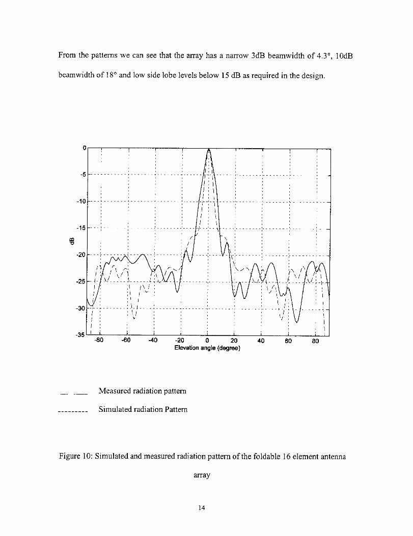
From the patternswe canseethat the arrayhasa narrow 3dB beamwidthof 4.3°, 10dB
beamwidth of 18 ° and low side lobe levels below 15 dB as required in the design.
1:13"O
"i .........
/I..... TI ...... L
;_ !\vI ' ' !J\
'I I , ! •
'il _I-I!I_ , \/
i i-60 -40 -20 0 20 40 60
Elevationangle (degree)-80 8O
Measured radiation pattern
Simulated radiation Pattern
Figure 10: Simulated and measured radiation pattem of the foldable 16 element antenna
array
14

2.7 Design 2
In the previous design the antenna was not well matched to the probe so a
different approach was taken to achieve a linear polarized antenna array which has better
matching. The configuration shown in Figure 11 produces directive beam on broadside
and is closely matched to the 50fl probe. In this design the antenna has two equal
subarrays composed of four elements each. Each subarray has patches of same width but
varying lengths unlike the previous design where the width was varied and the length
kept same.
In this design a pair of patches of same width and different length was taken as
one block and matched to the feeding probe. Each subarray consists of two of these pairs
(blocks) and is matched to 50f2 probe. The two subarrays are fed at the center 180 ° out of
phase.
Feed Points
Figure 11: Eight element antenna array
2.8 Eight element design
In this array design which has uniform excitation, curved transmission lines are
used. The half wavelength long connecting microstrip lines are curved to bring the
patches closer to each other and reduce the grating lobes. The single element design
15

procedure is as described in Section 2.3 with a design frequency of 1.413 GHz. The IE3D
simulation software package was used to arrive at the patch dimensions for a 50f_ match.
The dimension of the pair of patches obtained with IE3D is, L -- 93.2 ram, W = 77.1 mm
for the first patch and L = 100.2 ram, W = 77.1 mm for the second patch. The total length
is around 4 feet.
2.9 Results
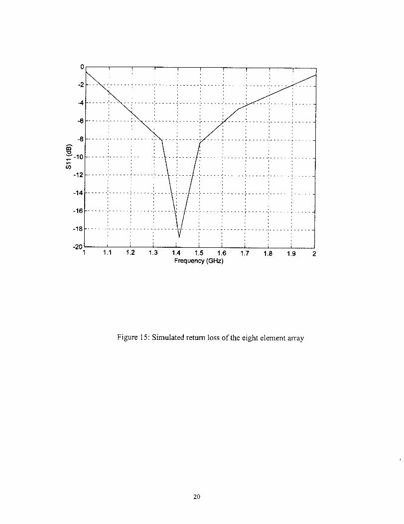
Input Impedance and return loss:
The simulated input impedance and return loss of the 8 element array is shown
below,
Frequency(GHz) Re[Z(1,1)] Im[Z(1,1)] dB[S(1,1)
1.000 12.58 131.60-0.553
1.333 172.30 10.50 -8.112
1.400 71.62 -15.16 -16.95
1.413 56.75 -5.54 -18.93
1.500 24.24 56.75 -3.358
1.667 92.54 92.09 -4.58
2.000 33.60 179.60 -0.7275
The simulated directivity of the array is 15 dB.
The simulated 2-D radiation pattern, polar pattern, 3-D mapped pattern and return
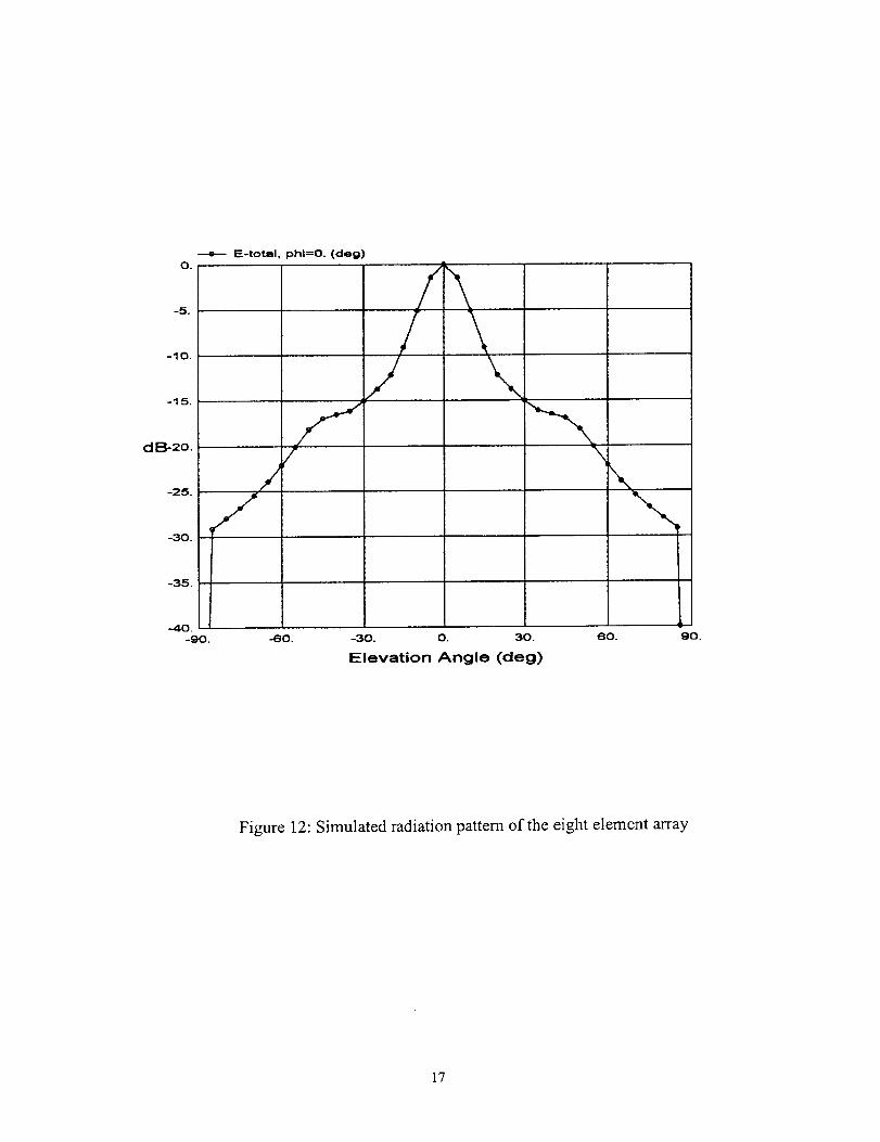
loss for the eight element array are shown in Figure 12, Figure 13 and Figure 14 and
Figure 15 respectively. The return loss was -19dB at the design frequency indicating a
good match. The pattern has a wider 3dB and 10dB beamwidth of 14.8 ° and 30 ° as
compared to 4.3 ° and 18 ° obtained with the first design. The pattern does not have
distinct side lobes, though the pattern falls below -15dB about 30 ° away from the main
lobe.
16
---e--- E-total, phl=O. (deg)O.
-5.
-10.
-15.
dB,-2o.
-25.
-30.
\\
-35,
.40.-90. -60. -30. 0. 30. 60.
Elevation Angle (deg)
90.
Figure 12: Simulated radiation pattern of the eight element array
17

(180-phi) direction
---4-- E-total, phl=O. (deg)0.0
150.0
180.0
Polar Elevation Pattern
30.0
1500
\ _60.0
phi direction
,0B
Figure 13: Simulated polar pattern of the eight element array
18

dB
( 90,
IE-totall
( 90,90)
Figure 14: Simulated mapped pattern of the eight element array
19
0
-2
-4
...6
-8
t,n.qo"" -10
O3
-12
-14
-16
| i | I I ]
! [ ! i ] ! ] !
....... , ...... T ..... ,...... '_ ...... t............ p ...... _ ...... i .....
-18i
q
-20 i i i i i i i ;1,1 1.2 1.3 1.4 1.5 1.6 1.7 1.8 1.9
Frequency (GHz)
Figure 15: Simulated return loss of the eight element array
20
CHAPTER 3
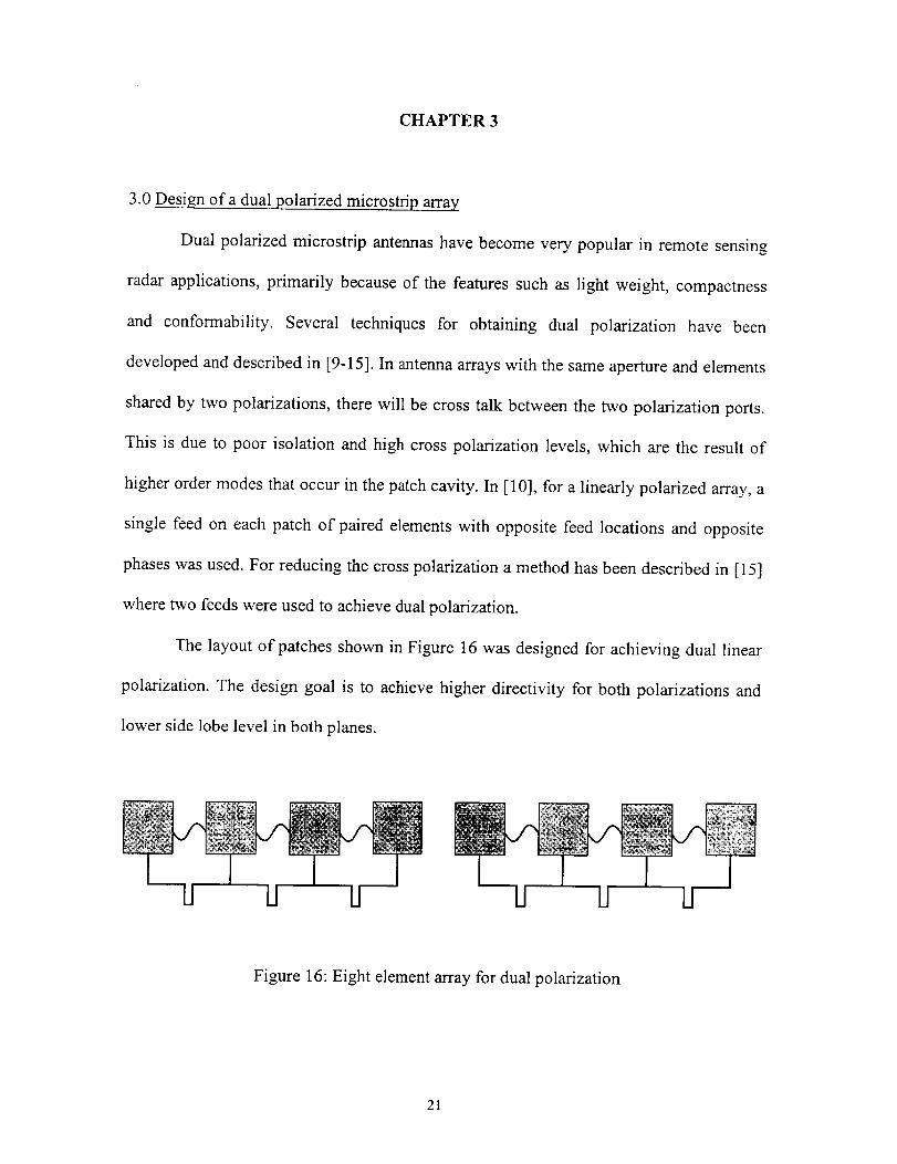
3.0 Design of a dual polarized microstrip array
Dual polarized microstrip antennas have become very popular in remote sensing
radar applications, primarily because of the features such as light weight, compactness
and conformability. Several techniques for obtaining dual polarization have been
developed and described in [9-15]. In antenna arrays with the same aperture and elements
shared by two polarizations, there will be cross talk between the two polarization ports.
This is due to poor isolation and high cross polarization levels, which are the result of
higher order modes that occur in the patch cavity. In [10], for a linearly polarized array, a
single feed on each patch of paired elements with opposite feed locations and opposite
phases was used. For reducing the cross polarization a method has been described in [15]
where two feeds were used to achieve dual polarization.
The layout of patches shown in Figure 16 was designed for achieving dual linear
polarization. The design goal is to achieve higher directivity for both polarizations and
lower side lobe level in both planes.
!1 U II U U II
Figure 16: Eight element array for dual polarization
21

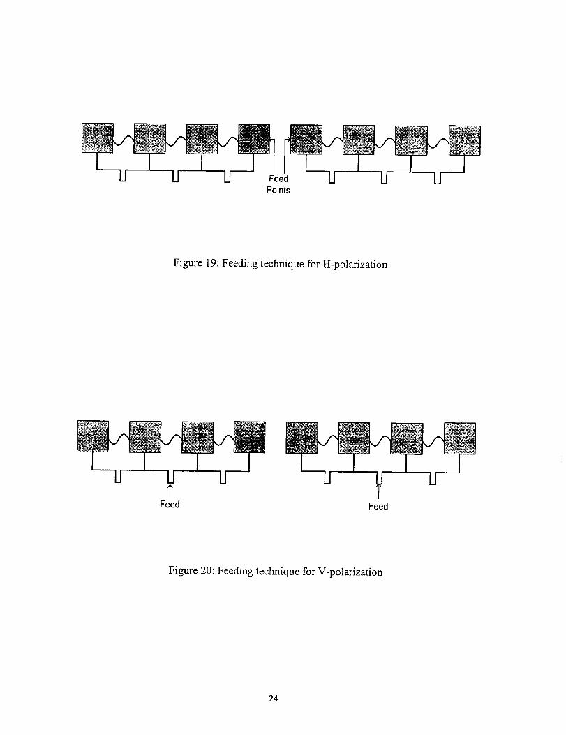
In this design, a seriesfeed for horizontal polarization (H-pol) and corporate
feedingfor vertical polarization(V-pol) wereused.For the H-pol the antennais center
fed at two pointsat thefirst elementof eachsubarraywith coaxialprobes.A 180° phase
differenceis introducedbetweenthetwo subarraysto producehighly directive beamon
broadside.For theV-pol the antennais fedby coaxialprobeswith microstriplines at two
points,onefor eachsubarray.Thetwo portsfor V-pol arefedwith samephaseto produce
highly directivebeamonbroadsideof theantenna.
3.1Design procedure for the eight element antenna
The dimensions obtained for the single patch is as described in Section 2.3 were
slightly modified for a 50f2 match for use in this array design. Using IE3D the
dimensions obtained are L = 92.7 mm and W = 86.7 mm. For the H-pol the dimension of
the patch is obtained such that it is matched to the 50f2 probe and the feed arrangement is
shown in Figure 17. In the array, the patches are connected with half wavelength long
curved lines to reduce the grating lobes. The patches are closer but the electrical
separation is equal to half wavelength. For the V-pol, a microstrip line is connected to the
patch and the input impedance of the patch at the thin microstrip line is 200fL The
structure of single patch for V-pol is shown in Figure 18. When the four patches of the
subarray are connected in parallel with the half wavelength lines, the subarray produces a
50f_ impedance at the feed. The final arrangement for the H-pol feeding is shown in
Figure 19 and for the V-pol feeding in Figure 20.
22

W
Feed Point for H-pol
L
Figure 17: Layout of a single patch for H-polarization
W
L
Feed Point for V-pol
Figure 18: Layout of a single patch for V-polarization
23
II 11 IJ Feed "El U LIPoints
Figure 19: Feeding technique for H-polarization
U Ut
Feed Feed
Figure 20: Feeding technique for V-polarization
24

3.2 Results
3.2.1 .Input impedance and return loss
The simulated input impedance of the antenna array for H-pol was 59_ and for
the V-pol was 75f2. The measured input impedance was 70_ for H-pol and 55f2 for V-
pol. The measured return loss for the antenna in V-pol is -26dB and for H-pol is -22dB.
3.2.2 Gain and efficiency measurement
Horizontal polarization:
Standard gain horn received power, Pref = -23.3 dBm
Test antenna received power, Ptest
Gain of the standard horn, Gref
= -28.1 dBm
= 16.73 dB
Gain of the of the antenna in H-polarization is,
Gte_t = -28.1 + 23.3 +16.73 = 11.93 dB
Simulated directivity of the antenna for H-pol = 14.1 dB
Efficiency of the antenna = 11.93 - 14.1 = -2.17 dB
= 60.67%
Vertical polarization:
Standard gain horn received Power, Pr_f = -23.3 dBm
Test antenna received power, Ptest
Gain of the standard horn, Gr_f
=-27.5 dBm
= 16.73 dB
Gain of the of the antenna in V-polarization is,
Gtest = -26.85 + 23.3 +16.73 = 13.18 dB
25

Simulateddirectivity of theantennafor V-pol = 16.0dB
Efficiency of theantenna= 13.18- 16.0=-2.82 dB
= 52.23%
3.2.3Simulated and measured radiation pattern
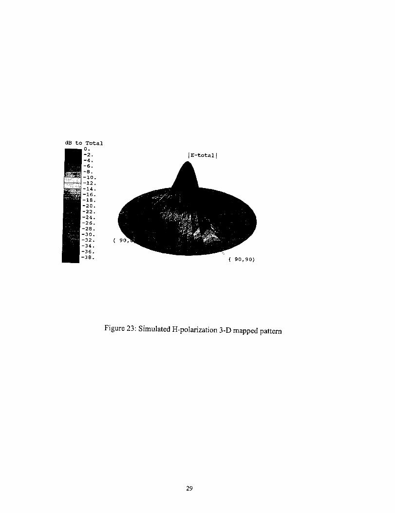
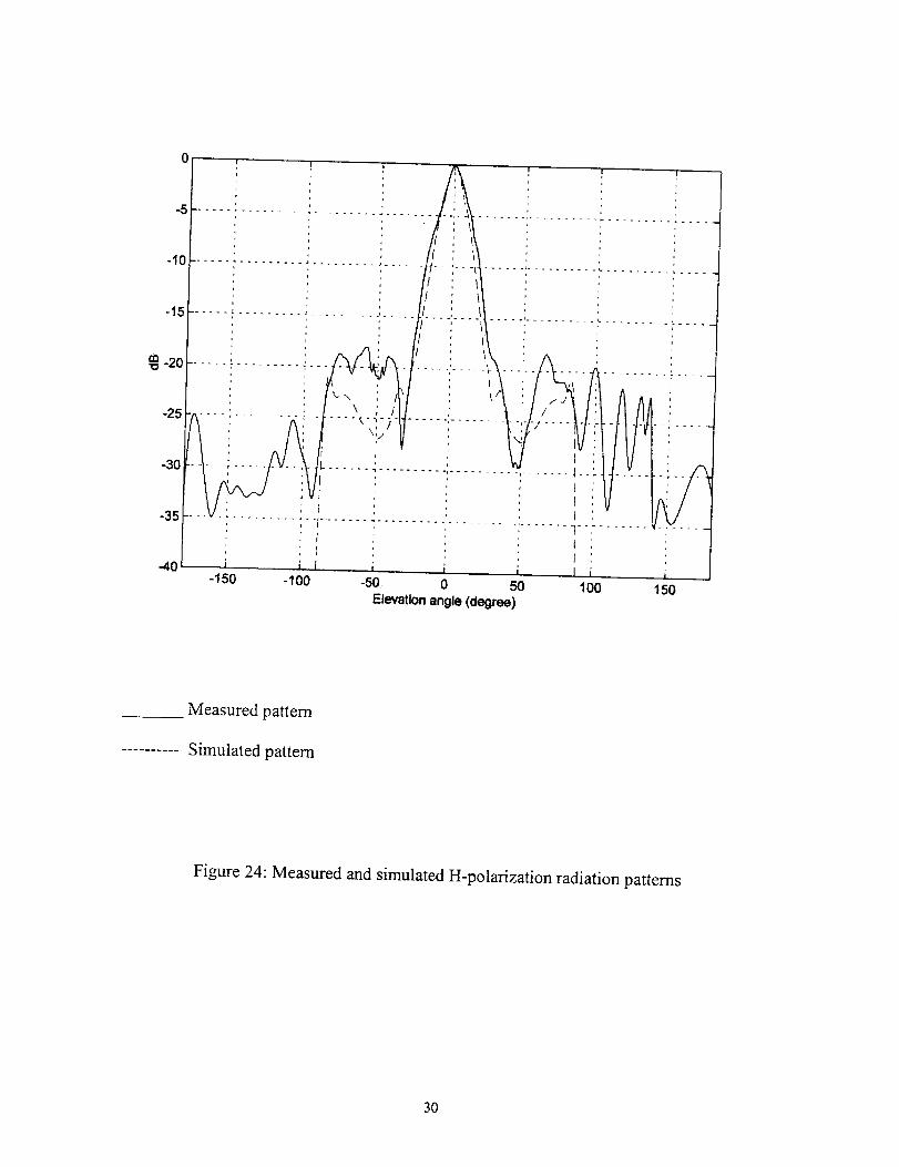
Figure 21, 22 and 23 show the simulated 2-D, polar, 3-D mapped radiation
patterns for the H-pol and Figure 24 shows the comparison between measured and
simulated 2-D radiation patterns for the H-pol. The measured pattern had some sidelobes
beyond 90 ° which did not appear in the simulated pattern.
26

-25.
--e-- E-total, phi=0. (deg)O.
-5.
-10.
-1,5.
d B-20.
-30.
-3,5.
-,40.
-go. -60. -30. O. 30.
Elevation Angle (deg)
60. 90.
Figure 21 : Simulated H-polarization radiation pattern
27

--0.-- E-total, phi--0. (dag)
0.0
_o.o__o.o
oo4/,- 75{:;X_-] t "- ", \- -A . / ",i.- .... :-_._ \ \ \ .>?o.o
l I ' if/ 7<..,.\_%.-x- \\_ "I \ ',I(1eO-phi) direction / I ' I _ -.kl//"._ I i _-- i _ ; ',/ _hi d_,,._,,_
oLo -,_.o {-z_.o _,-3&o_--_'._.36 o;-26 of ,A _ I,,l_ ..........
\\\ \\ \\.'_>\'-_'IJ_I_WI II ,/1\ \ _"\_ \ r--__--\ / /\/.. / /
\.'_ \ \ Y--. I ..._e / I -L ]12o o,. < \ .'_. . _- / /
\ \ -.t "--__1 -_ \ i / /'_2o.o
_'W_" ..... iiS'I/
15_0
180.0
Polar Elevation Pattern
Figure 22: Simulated H-polarization polar pattern
28
( 90_
IE-total I
( 90, 90)
Figure 23: Simulated H-polarization 3-D mapped pattern
29
I
-150 -100150
Measured pattern
.......... Simulated pattern
Figure 24: Measured and simulated H-polarization radiation patterns
30
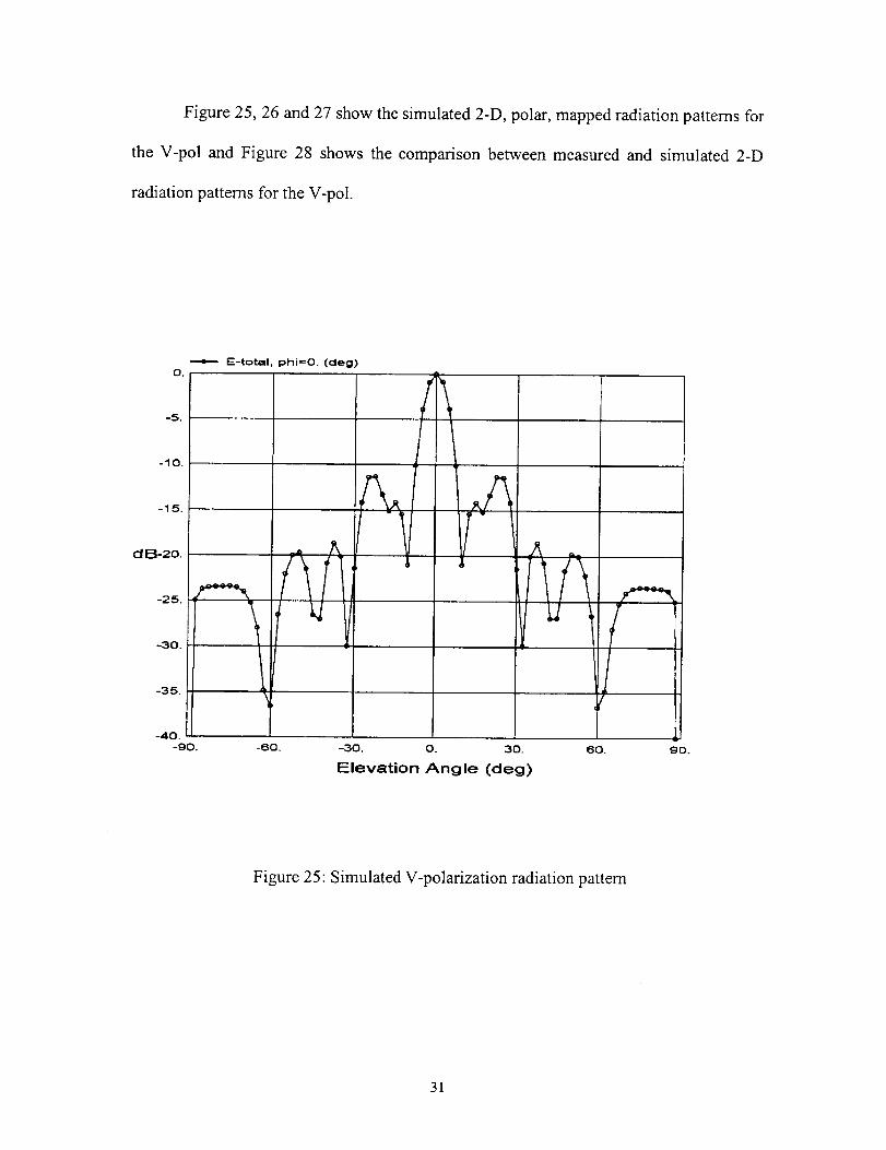
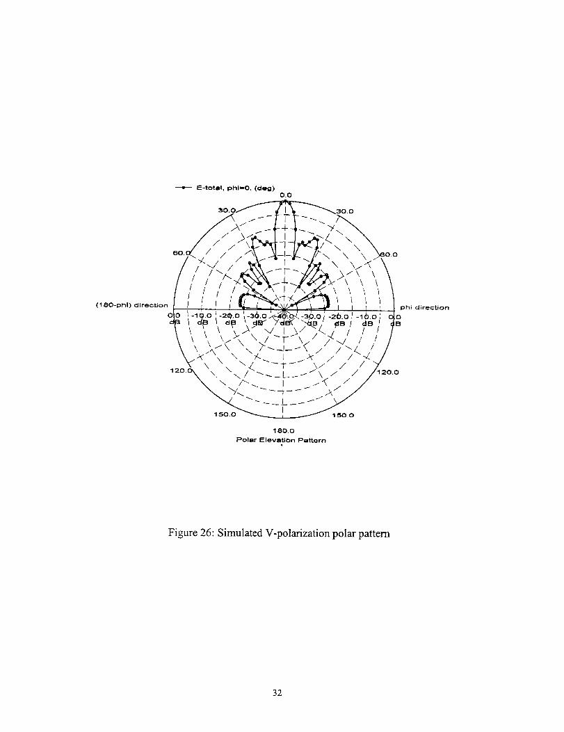
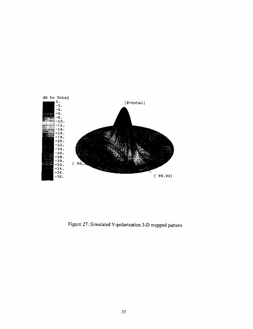
Figure 25, 26 and 27 show the simulated 2-D, polar, mapped radiation patterns for
the V-pol and Figure 28 shows the comparison between measured and simulated 2-D
radiation patterns for the V-pol.
E-total, phi=O. (cleg)O.
dB-2o.
-40.
-9o. -60. -3o. o. 30. 6o. 9o.
Elevation Angle (deg)
Figure 25: Simulated V-polarization radiation pattern
31
E-totll, Iohl==O. ((:leg)0.0
(180-phi) direction
_30.0
\ \ /
phi direction
0IB
180.0
Polar Elevation Pattern
Figure 26: Simulated V-polarization polar pattern
32
( 90
IE-total I
(90,90)
Figure 27: Simulated V-polarization 3-D mapped pattern
33

-20
-25
-30
:\/ 1I
........ !
8O
Measured pattern
........... Simulated pattem
Figure 28: Measured and simulated V-polarization radiation patterns
34

From the results we can see that the measured and simulated input impedance
agree well and the 2-D radiation patterns shown in Figure 24 and 28 show excellent
agreement between the measured and simulated results for the beamwidth and for the
location and level of the side lobes.
35

CONCLUSION
The design of a series fed linearly polarized and a dual polarized antenna are
presented. The array has to have low loss, a highly directive beam and low side lobe
level. In addition the array should be foldable to allow transportation into space. The
designs were simulated using the IE3D electromagnetic simulation tool. The design starts
with obtaining the dimensions of a single microstrip patch at the design frequency of
1.413 GHz. An inverted microstrip antenna configuration is chosen because this
configuration provides less dielectric and dispersion losses than the convention microstrip
antenna configuration. RT Duroid RO3003 with a dielectric constant 3.0 was chosen as
the dielectric cover for the inverted patches which were placed on Rohacell foam
substrate with a dielectric constant of 1.08. In the first design, the patch width was
reduced in constant ratio outward towards the end of the subarray to get higher directivity
and low side lobes. The simulated and measured radiation patterns obtained agree very
well. To get a better match at the feed, a different approach was taken by matching pairs
of patches to 50f_ and using two of such pairs to form one subarray. In this approach the
length of the patches were varied keeping the width the same.
For obtaining dual polarization the single patch dimension was optimized using
IE3D and an almost square patch was used. The subarray consists of the four patches of
equal dimension. Curved microstrip transmission lines were used to reduce side lobes for
series feeding for the horizontal polarization and a corporate feed network was used for
the vertical polarization. The measured radiation patterns agree very well with the
simulated patterns for both polarizations.
36

RE FERENCE S
[1] Metzler T., "Microstrip Series Arrays," Proceedings of The Workshop on Printed
Circuit Antenna Technology, October 17-19, 1979.
[2] Mahbub R.,"Design of a foldable series fed microstrip array antenna for radiometric
applications," University of Central Florida, Orlando, Florida, 1998.
[3] Wu K.-L., Spenuk M., Litva J., Fang D. -G., "Feed network effects on the radiation
pattern of series-fed microstrip antenna arrays," IEE Proceedings-H, Vol. 138, No.
3, June 1991.
[4] Kitazawa T. et al., "Planer transmission lines with finitely thick conductors and
lossy substrates," IEEE Int. Microwave Symp. Digest, June 1991.
[5] Gauthier G. P., Courtay A., and Rebeiz G. M., "Microstrip Antennas on
Synthesized Low Dielectric-Constant Substrates," IEEE Trans. On Antennas and
Propagation, Vol. 45, No. 8, August 1997.
[6] Zealand Software Inc.
[7] Splitt G. and Davidovitz M., "Guidelines for design of electromagnetically coupled
microstrip patch antennas on two-layer substrates," IEEE Trans. Antennas
Propagation, vol. 38, pp. 90-94, July 1990.
[8] Bancroft R., "Accurate Design of Dual - Band Patch Antennas," Microwave & RF,
September, 1988.
[9] Levine E. and Shtrikman S., "Experimental comparison between four dual polarized
microstrip antennas," Microwave and Optical Technology Letters, vol. 3, pp-17-
18, January 1990.
37

[15]
[10] Huang J., "Low cross-pol linearly polarized microstrip array," IEEE AP-S
InternationalSymposiumDigest,pp-285-288,May 1982.
[11] Maci S., Gentili G. B. and Avitabile G., "Single layer dual frequency patch
antenna," Microwaveand Optical TechnologyLetters,vol. 29, no. 16, pp-1441-
1443.
[12] Maci S., Gentili G. B., PiazzesiP.andSalvadorC., "A dualbandslot loadedpatch
antenna,"IEEProceedings-H,vol. 142,pp-225-232,1995.
[13] Huang J., "Dual PolarizedMicrostrip Array with High Isolation and Low Cross
Polarization," Microwaveand Optical TechnologyLetters,vol. 4, no. 3, pp-99-
103,February1991.
[14] HuangJ.,Lou M., FeriaD. andKim Y., "An InflatableL-bandMicrostrip SAR
Array," IEEEAP-SInternationalSymposiumDigest,pp-2100-2103,1998.
ZawadzkiM., and HuangJ., "A DualPolarizedMicrostrip SubArray Antennafor
anInflatableL-bandSyntheticApertureRadar," IEEEAP-S International
SymposiumDigest,pp-276-279,July 1999.
38