final report - nissan-global.com
TRANSCRIPT

31st March 2021
Final Report
Research period: 31th July 2020 to 31st March 2021
Title:
“Searching the Approaches for Lithium-Ion Battery (LIB)
Second Life Performance Improvement”
“FM Lab” Co Ltd
Daniil Itkis
Summary
Title
Searching the Approaches for Lithium-ion Battery (LIB) Second Life
Performance Improvement
Research period
31th July 2020 to 31st March 2021
Development / Survey Representative
“FM Lab”Co Ltd Dr. Daniil Itkis
Conductor
“FM Lab”Co Ltd Dr. Daniil Itkis
Nissan Motor Co., Ltd. Kazuyuki Shiratori
Yoshiko Hisitani
Takako Toda
Subcontractor
“SC-Tek” LLC Dr. Mikhail Kondratenko
Purpose
The main aim of the project is to monitor and to evaluate promising approaches, which
can enable enhancement of the LIB performance during its second life (i.e. approaches
enabling recovery of battery capacity and/or power after it was used for some time and
has been degraded).
Project Tasks
Task 1. Verification of recovery with the original method using laminated (pouch) cells:
1.1 Further screening of lithium salts – solubility and oxidation potentials
1.2 Ageing of pouch cells
1.3 Washing/refilling of cycled cells
Task 2. Design of a dedicated cell structure capable for capacity recovery by the original
method, even in a non-dry environment:
2.1 Developing the cell concept
2.2 Cell design & sketching
2.3 Parts fabrication & cell assembly
2.4 Cell testing
Task 3. Drafting the conceptual design of a high-pressure rig for laminated (pouch) cell
regeneration using supercritical fluids without dry environment
Task 4. Final report preparation
Summary
Testing of the suggested recovery approach on pouch cells revealed significant
inaccuracy caused by non-optimized experimental conditions. Opening, washing, and
refiling the cells with ordinary electrolyte leads to increased degradation rate and
significant scatter in the cycling data. It makes hard to accurately check the effect of
washing/recovery electrolyte refilling.
Although pouch cell washing by supercritical fluid and refilling with recovery electrolyte
candidates did not result in capacity improvement, refilling with Li lactate-containg
electrolyte significantly slowed down the degradation giving a hope of recovery possibility
if experimental conditions are improved.
We suggested, designed, and tested a dedicated electrochemical cell (high-pressure
electrochemical cell, HPEC), which we believe can enable more accurate experimental
conditions for testing our recovery approach. The cell operation was demonstrated.
Further research should be done with longer and more standardized cell ageing to avoid
unpredictable results. Pouch cell opening and resealing protocols are to be optimized.

Abbreviations
BPR back-pressure regulator
CC constant current
CV constant voltage
CVA cyclic voltammetry
DMC dimethyl carbonate
EC ethylene carbonate
EIS electrochemical impedance spectroscopy
HPEC high-pressure electrochemical cell
ICP MS inductively coupled plasma mass spectroscopy
LAM loss of active materials
LFP lithium iron phosphate LiFePO4
LIB lithium-ion battery
LLI loss of lithium inventory
LMO lithium manganese oxide LiMn2O4
MeCN acetonitrile
NMC lithium-nickel-manganese-cobalt oxide Li(Ni, Mn, Co)O2
NMP N-methyl-2-pyrrolidone
PEEK polyetheretherketone
PVDF polyvinylidene difluoride
scCO2 supercritical carbon dioxide
SCF supercritical fluid
SEI solid-electrolyte interphase
SEM scanning electron microscopy
TBAP tetrabutylammonium perchlorate
Contents
Abbreviations .................................................................................................................. 4
Contents ......................................................................................................................... 5
Introduction ..................................................................................................................... 6
Verification of the pouch cells recovery .......................................................................... 8
Screening of the salts for recovery electrolyte ............................................................ 8
Ageing of the pouch cells .......................................................................................... 10
Supercritical washing of the pouch cells ................................................................... 12
Refilling the pouch cells ............................................................................................ 14
High-pressure electrochemical cell design and testing ................................................. 18
HPEC design ............................................................................................................. 18
HPEC testing ............................................................................................................. 21
Concept of the rig for pouch cell recovery .................................................................... 25
Conclusions .................................................................................................................. 27
Challenges for the future .............................................................................................. 27
References ................................................................................................................... 28
Introduction
The demands for LIBs continue to grow, one of the main drivers today is the production
of electric vehicles, which have high energy efficiency (ca. 80% or higher vs. 12-30% for
cars with internal combustion engines) [1]. According to various estimates [2,3], the
annual amount of LIB waste is ca. 200-500 million tons, of which 5-15 wt. % belong to
cobalt - an expensive and toxic element, and 2–7 wt.% - to lithium. Due to expected
acceleration of LIB production growth the battery recycling [2–6] and “second life” [7]
became quite hot topics driven by both economic and environmental factors. Although
battery recycling is rather cost- and labour-consuming, increasing amount of spent
batteries pushes active investments into this field. Reusing spent batteries in the
applications not requiring high performance – battery “second life” – is on the contrary
much less expensive. However, there are serious limitations on energy and power of the
spent batteries, so the number of applications is quite limited. Economic benefits of using
the spent batteries as is after EoL are also not obvious due to deteriorated performance
[7].
This project aims to improve the performance of the spent lithium-ion batteries, to make
it possible to use recovered ones during its “second life” in demanding applications such
as electric vehicles. Although recovery of initial properties of the as-produced battery
seems to be impossible, we are searching the approaches for partial restoring battery
capacity and/or power. The focus of the project is evaluating the approach, which was
suggested at the previous stages for enhancement of the LIB performance during its
second life.
Among the numerous reasons for the battery performance loss [8] the group identified
as loss of lithium inventory was suggested by us as the most important. During recent
years this hypothesis was confirmed for batteries used in EVs [9] and in grid-storage
applications [10]. It was also found to be true for various cathode chemistries including
NMC, LMO, and LFP. The LLI is driven mainly by damaging of initial SEI layer and its re-
formation leading to Li+ capture in the form of as Li2O, LiF, Li2CO3 and possibly other
products. Thus, lithium is partially immobilised in SEI, thus the number of active charge
carriers in the cell decreases and the capacity fades. As well, excessive SEI increases
the negative electrode resistance thus lowering the cell power characteristics.
The main idea for restoring the spent battery capacity is based primarily on removing the
old electrolyte and partially SEI layer from the surface of the negative electrode and
further “refilling” of lithium inventory in the cell. This is illustrated in Figure 1, which shows

partial immobilization of lithium ions in SEI during battery life, removal of old SEI, refilling
the lithium inventory using special “recovery” electrolytes and reformation of SEI (lithium
oxalate additive to prepare “recovery” electrolyte is shown as an example).
Figure 1. Schematic illustration of the project general idea. Lithium host materials are shown as green (anode) and
orange (cathode) layers. Dark blue circles are lithium ions. Dotted circumflexes denote potential host sites for lithium,
which are not filled.
Although complete removal of SEI depicted in Figure 1 was not yet confirmed, we
previously demonstrated the ability of extracting the old electrolyte and from the
electrodes using supercritical fluids, which have good permeation ability (see the reports
for FY 2018 and 2019). During this project stage we further investigated removal of
electrolyte from the commercial pouch cells by supercritical fluids (sc-CO2 with MeCN as
a co-solvent). The experimental setup build previously was found to be able to wash out
the electrolyte from pouch cells, which was controlled by ICP MS and by measuring the
cell impedance (high impedance of the washed cell evidences for the electrolyte
removal). The candidates for recovery electrolyte suggested before (Li oxalate, Li
acetate) were found to be poorly soluble in 1M LiPF6 in EC:DMC electrolyte and can be
hardly employed for lithium inventory recovery. Because of that we continued the search
for the compounds, which can enable lithium inventory refilling. High-pressure
electrochemical cell for cycling model lithium-ion battery was developed. It enables the
internal cell volume washing and electrolyte refilling without the need for cell disassembly
in argon-filled glove-box environment. The cell was tested by cycling with graphite vs.
NMC electrodes, washing the electrolyte and refilling. The general concept on upgrading
the designed cell into a system for real battery recovery was drafted.
Verification of the pouch cells recovery
Screening of the salts for recovery electrolyte As state above, repeated SEI formation leads to active lithium inventory loss, thus, the
stated red/ox balance between cathode and anode materials becomes disrupted (see
Figure 1). For balancing red/ox processes and recovering lithium inventory we tried
several additions to electrolyte listed in Table 1. While selecting additives for the tests,
we used two criteria: 1) the additive hypothetically can be oxidized irreversibly at
moderate potentials with gaseous products formation; 2) it should provide Li+ for lithium
inventory recovery.
We monitored the lithium salts with well-known oxidizable anions: oxalate and formate.
Also, acetate and nitrate, according to the literature, can be oxidized at the potentials
close to electrolyte oxidative stability boundary. Acetoacetate and lactate can be
converted in CO2 and H2O in living cells and be easily oxidized. However, solubility of
organic salts in organic carbonates (EC:DMC 1:1 v/v) was found to be very low. As
aprotic polar solvents, carbonates are unable to solvate anions, and solubility decreases
with an increasing anion charge density (i.e., relation between anion charge and its size).
For testing the electrochemical behavior of the additives, we used 3-electrode analytical
glass cell with glassy carbon (GC) as a working electrode, Pt wire as a counter electrode,
polypyrrol on Pt wire (PPy+/PPy) as a reference electrode. After each experiment the
reference electrode was calibrated by measuring the ferrocene/ferrocene+ redox couple
potential. The EC:DMC mixture (1:1 by vol.) was used as a solvent, 0.1 M TBAP was
dissolved and played a role of supporting electrolyte. Concentration of tested compounds
varied from 0.05 to 0.1 M. Cycling voltammetry studies were done with a sweep rate of
50 mV/s inside the electrolyte stability window. Acetate and oxalate were tested
previously (see the report for FY 2019). All results voltammograms are presented in
Figure 2.
As all of the tested lithium salts were found to be either poorly soluble or demonstrated
very little redox activity in these model experiments, we suggested a new approach:
using lithium-free methyl formate and dimethyl oxalate as additives. Despite lithium
absence, side reactions with an excess of LiPF6 can possibly produce Li+ for lithium
inventory recovery. These compounds were found to be nicely soluble in EC:DMC and
can be easily oxidized. However, the possibility to use them for recovery of full lithium-
ion cells needs further testing.

Table 1 Selected compounds for candidate recovery electrolytes.
Name Formula Achievements Problems
Lithium oxalate
- Oxidation onset between 3.5-
4.0 V vs. Li+/Li
- Compensates lithium inventory
losses in solid form being added
to cathode material
Very low solubility: exact solubility
value was not measured, but very
high impedance of the saturated
solution in EC:DMC (without LiPF6)
is an indirect evidence
Lithium acetate
- Oxidation onset between 3.4-
4.0 V vs. Li+/Li
Very low solubility: exact solubility
value was not measured, but very
high impedance of the saturated
solution in EC:DMC (without LiPF6)
is an indirect evidence
Lithium nitrate LiNO3 - Solubility in EC:DMC is at least
0.05 M
- Oxidation onset close to 4 V vs.
Li+/Li, higher than for other salts
- Evolution of nitrogen oxides
(environmental impact)
Lithium formate
- Solubility at least 0.05 M in
EC:DMC
- High hygroscopicity; only hydrate is
commercially available, necessity to
dry
Lithium
acetoacetate
- Oxidation onset at low
potentials (starting at ca. 3.1 –
3.2 V vs. Li+/Li)
- Low chemical and thermal stability
- Tendency to form sol instead of
true solution
Lithium lactate
- No visible oxidation activity up to
4.5 V vs. Li+/Li
- Solubility not higher than 0.01 M
Methyl
formate*
- Liquid, solubility in EC:DMC is
at least 0.1 M
- Stable oxidation peak at 4.7 V vs.
Li+/Li (should be double checked)
Dimethyl
oxalate*
- Solubility in EC:DMC is at least
0.1 M
- Oxidation onset between 3.7-
4.5 V vs. Li+/Li
- Reduction onset at 2-2.4 V vs.
Li+/Li
* require addition of extra concentration of LiPF6 for lithium inventory refilling; charge compensation is expected to be
provided by interaction of residual PF6- anions with the oxidation products.

1.76 2.26 2.76 3.26 3.76 4.26 4.76 5.26
-0.02
-0.01
0.00
0.01
0.02
0.03
I, m
A
E vs Li+/Li , V
LiOOCH LiLact LiAcAcO LiNO3 HCOOMe (COOMe)2
Figure 2. CVA curves for tested candidates for recovery electrolyte. Lithium formate (LiOOCH), lactate (LiLact),
acetoacetate (LiAcAcO), nitrate (LiNO3), methyl formate (HCOOMe), and dimethyl oxalate ((COOMe)2) in EC:DMC with
0.1 M TBAP as a supporting electrolyte. The voltage sweep rate 50 mV/s.
Ageing of the pouch cells For testing the approach on commercially produced pouch cells we selected available
batteries with geometric dimensions allowing the washing in the experimental setup built
during previous project stage.
Figure 3. Photograph of the pouch cell used for cycling
The used cells were produced by EEMB ltd. (model LP401730). The picture of the cell
is shown in Figure 3. The cells comprise graphite – NMC chemistry. Its properties are
summarized in Table 2.

Table 2. The properties of the used pouch cells
Parameter Value
Dimensions 30 mm × 17 mm × 4 mm
Nominal capacity 150 mAh at C/5
Internal resistance < 300 mOhms
Recommended upper cutoff voltage 4.2 V
Recommended lower cutoff voltage 2.75 V
Average measured initial charge capacity 157.3 ± 2.6 mAh at C/2
Average measured initial discharge capacity 156.9 ± 2.7 mAh at C/2
The cells ageing was performed at a room temperature (23 ± 2°C) using multichannel
Biologic SAS MPG2 potentiostats. Discharge was performed at 75 mA (C/2) down to
2.75 V potential. Charge was performed at CC/CV regime. Current was kept at 75 mA
until the voltage reached the upper voltage threshold, which varied from one batch of the
cells to another (4.20, 4.30, 4.35, and 4.40 V). Then the cell was kept at constant voltage
until the current went down to 7.5 mA (10-fold decrease).
Figure 4 Average capacity fade for the pouch cells during cycling with different upper cut-off voltage (indicated in the
legends). Left graph shows absolute capacity values, right – the value normalized by the first cycle. Points show mean
values, error bars indicate standard deviations among the cells tested with certain upper voltage limit.
Figure 4 shows the averaged capacity fade for the aged cells. As expected, overcharging

the cells to higher voltage resulted in higher initial capacities. At the same time, the
degradation rate increased enabling to reach higher capacity loss in the limited
timeframe. The cells charged up to 4.35V during ageing demonstrated unexpected
behaviour degrading faster than those with stronger overcharge (4.40V). While this
particular case can be connected with insufficient statistics (only two cells were aged by
discharge/charge to 4.35V), it should be noticed that the overcharge conditions can affect
the contributions of different degradation mechanisms to capacity loss. One can imagine,
as an example, the intensified Ni dissolution from the cathode material at high voltages
leading to increased contribution of LAM degradation mode. Being constrained by the
timeframe, however, we used the cells aged at different conditions for washing/refilling
experiments. Nevertheless, the consequences of various ageing regimes, as well as
other ageing approaches are to be thoroughly analysed in future.
The cells cycled with an overcharge were finally discharged/charge 10 times with 4.20V
upper voltage limit to enable the comparison of the capacity drop between the cells aged
in different conditions.
Supercritical washing of the pouch cells The experiments were carried out using the setup proposed at the previous stage of the
project (Figure 5). CO2 pressure was set to 300 bar, thermostat exposition temperature
= 60 °C, fluid flow 4 ml/min.
Figure 5. Supercritical fluid extraction setup scheme.
Each washing experiment consisted of three steps: 1) preliminary washing of the system

with deionized water, 2) washing the pouch cell with supercritical carbon dioxide with a
co-solvent, 3) final washing of the system (cell removed) with water. A detailed
description of each stage is given in the report for FY 2019.
We used the developed washing method for commercial pouch cells. For washing the
aged cells were cut by knife on the one side and placed into the reactor II, this operation
was done inside an argon-filled glove box. The reactor was sealed and isolated by the
valves and connected to the high-pressure system. 50 ml of co-solvent (acetonitrile) was
poured in the reactor I; the entire experimental setup was purged with CO2 for 90 minutes,
and as a result CO2 was fed into reactor I, mixed with co-solvent, got into reactor II, mixed
with electrolyte in the pouch cell and got into the flask with water. Analysing the ICP MS
data, we plotted the curves showing the concentration of washed lithium versus the
volume of CO2 flushed through the system. Additionally, the procedures of pre-washing
and post-washing of the reactor with water were carried out, ensuring the control of the
purity of the capillaries of the setup. The lithium concentration in the post-washings was
more than a hundred times lower than in the main washing procedure (CO2 + co-solvent),
which indicates that the minimum amount of lithium accumulated in the capillaries.
Figure 6 shows a typical graph of lithium extraction from the pouch cell. The data are
presented as a cumulative total. The amount of Li washed from the pouch cell reaches
the saturation level.
120 180 240 300 360
1,12
1,16
1,20
1,24
1,28
tota
l Li w
ashe
d, m
ol *
10
-5
CO2 used, ml
CO2+cosolvent washing
Figure 6. The amount of lithium leached from the pouch cell vs. the amount of CO2 flushed though the cell. The plot
shows typical example for washing one of the aged cells. The amount of Li was detected by means of ICP-MS analysis.
MeCN used as a co-solvent.
Based on the experimental data obtained for 13 aged pouch cells, the median amount
of leached lithium was 1.5*10-5 mol. Thus, the possibility of supercritical extraction of
lithium from commercial pouch cells was demonstrated.
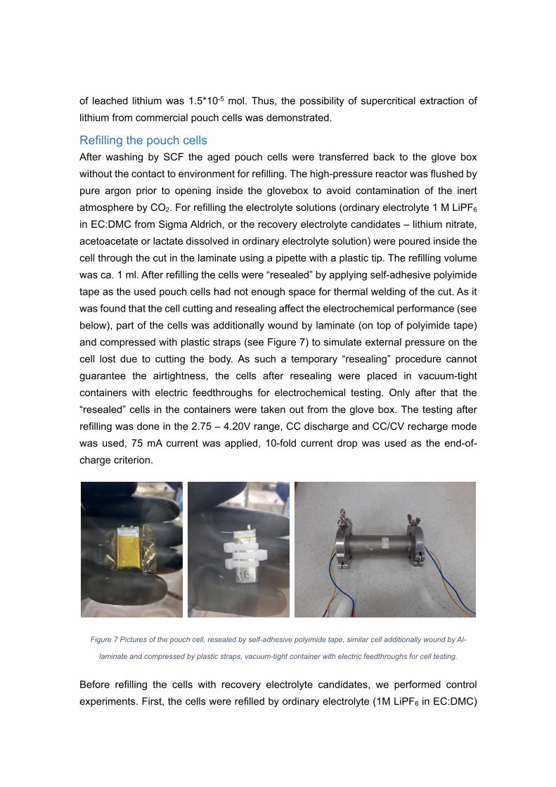
Refilling the pouch cells After washing by SCF the aged pouch cells were transferred back to the glove box
without the contact to environment for refilling. The high-pressure reactor was flushed by
pure argon prior to opening inside the glovebox to avoid contamination of the inert
atmosphere by CO2. For refilling the electrolyte solutions (ordinary electrolyte 1 M LiPF6
in EC:DMC from Sigma Aldrich, or the recovery electrolyte candidates – lithium nitrate,
acetoacetate or lactate dissolved in ordinary electrolyte solution) were poured inside the
cell through the cut in the laminate using a pipette with a plastic tip. The refilling volume
was ca. 1 ml. After refilling the cells were “resealed” by applying self-adhesive polyimide
tape as the used pouch cells had not enough space for thermal welding of the cut. As it
was found that the cell cutting and resealing affect the electrochemical performance (see
below), part of the cells was additionally wound by laminate (on top of polyimide tape)
and compressed with plastic straps (see Figure 7) to simulate external pressure on the
cell lost due to cutting the body. As such a temporary “resealing” procedure cannot
guarantee the airtightness, the cells after resealing were placed in vacuum-tight
containers with electric feedthroughs for electrochemical testing. Only after that the
“resealed” cells in the containers were taken out from the glove box. The testing after
refilling was done in the 2.75 – 4.20V range, CC discharge and CC/CV recharge mode
was used, 75 mA current was applied, 10-fold current drop was used as the end-of-
charge criterion.
Figure 7 Pictures of the pouch cell, resealed by self-adhesive polyimide tape, similar cell additionally wound by Al-
laminate and compressed by plastic straps, vacuum-tight container with electric feedthroughs for cell testing.
Before refilling the cells with recovery electrolyte candidates, we performed control
experiments. First, the cells were refilled by ordinary electrolyte (1M LiPF6 in EC:DMC)

after washing. Second, ordinary electrolyte was poured into the cell without washing by
SCF (just opening the cell, pouring additional electrolyte, sealing by tape). The results
are summarized in Figure 8. Control experiments revealed that fast degradation occur
after opening/“resealing” the used type of pouch cells. At the same time data is much
scattered. Now we see two main reasons for this. First, it can relate to the loss of
compression between electrodes, as the cell is resealed without evacuation, thus there
is no pressure difference enabling the compression of a jelly roll inside. Second, possible
contamination with humidity due to impropper MeCN quality (co-solvent in supercritical
washing). Both reasons to be further checked. Trials of applying additional external
compression to the cell were already performed for the batteries refilled with lithium
lactate and acetoacetate (see below). Monitoring of the MeCN purity and humidity to be
performed.
Figure 8. (Left) relative capacity fade (normalized by the first cycle of a certain cell) before and after opening the cell,
washing by SCF, refiling with ordinary electrolyte, and resealing by polyimide tape (without external compression of the
cell). Three pouch cells were aged in the same conditions with 4.2V upper voltage cutoff. (Right) Relative capacity fade
(normalized by the first cycle of a certain cell) before and after opening the cell, injecting additional volume of ordinary
electrolyte and cell sealing by polyimide tape (no supercritical wash).
Although at first glance it seems that supercritical washing leads to sudden capacity drop
after refilling, while simple cut immediately followed by electrolyte injection and resealing
increases the capacity, we think that no conclusion can be drawn at this stage. The
results are to be checked again with improved experimental conditions (control of the co-
solvent quality, external pressure applied to the cell after resealing). Even more accurate
testing can be expected from experiments with HPEC (see the corresponding chapter of
this report).
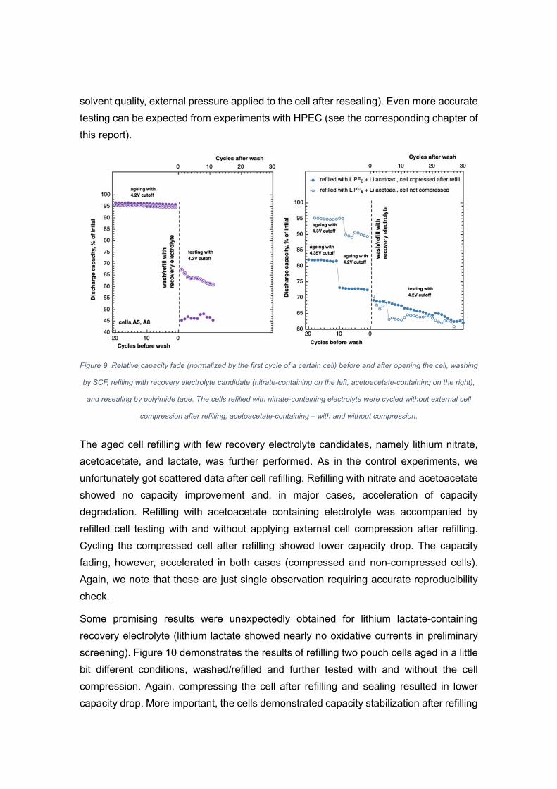
Figure 9. Relative capacity fade (normalized by the first cycle of a certain cell) before and after opening the cell, washing
by SCF, refiling with recovery electrolyte candidate (nitrate-containing on the left, acetoacetate-containing on the right),
and resealing by polyimide tape. The cells refilled with nitrate-containing electrolyte were cycled without external cell
compression after refilling; acetoacetate-containing – with and without compression.
The aged cell refilling with few recovery electrolyte candidates, namely lithium nitrate,
acetoacetate, and lactate, was further performed. As in the control experiments, we
unfortunately got scattered data after cell refilling. Refilling with nitrate and acetoacetate
showed no capacity improvement and, in major cases, acceleration of capacity
degradation. Refilling with acetoacetate containing electrolyte was accompanied by
refilled cell testing with and without applying external cell compression after refilling.
Cycling the compressed cell after refilling showed lower capacity drop. The capacity
fading, however, accelerated in both cases (compressed and non-compressed cells).
Again, we note that these are just single observation requiring accurate reproducibility
check.
Some promising results were unexpectedly obtained for lithium lactate-containing
recovery electrolyte (lithium lactate showed nearly no oxidative currents in preliminary
screening). Figure 10 demonstrates the results of refilling two pouch cells aged in a little
bit different conditions, washed/refilled and further tested with and without the cell
compression. Again, compressing the cell after refilling and sealing resulted in lower
capacity drop. More important, the cells demonstrated capacity stabilization after refilling
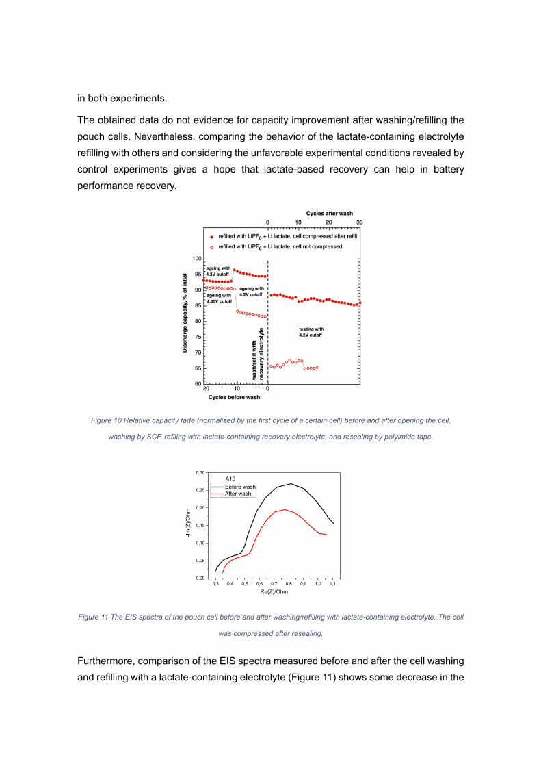
in both experiments.
The obtained data do not evidence for capacity improvement after washing/refilling the
pouch cells. Nevertheless, comparing the behavior of the lactate-containing electrolyte
refilling with others and considering the unfavorable experimental conditions revealed by
control experiments gives a hope that lactate-based recovery can help in battery
performance recovery.
Figure 10 Relative capacity fade (normalized by the first cycle of a certain cell) before and after opening the cell,
washing by SCF, refiling with lactate-containing recovery electrolyte, and resealing by polyimide tape.
0,3 0,4 0,5 0,6 0,7 0,8 0,9 1,0 1,10,00
0,05
0,10
0,15
0,20
0,25
0,30
-Im
(Z)/
Ohm
Re(Z)/Ohm
Before wash After wash
A15
Figure 11 The EIS spectra of the pouch cell before and after washing/refilling with lactate-containing electrolyte. The cell
was compressed after resealing.
Furthermore, comparison of the EIS spectra measured before and after the cell washing
and refilling with a lactate-containing electrolyte (Figure 11) shows some decrease in the

diameter of the lower-frequency depressed semicircle, which can indirectly evidence for
at least partial SEI removal. Additional EIS studies in more accurate conditions, as well
as the cell C-rate testing before and after refilling are needed to clarify the possibility of
battery power recovery.
High-pressure electrochemical cell design and testing
HPEC design On the present stage of the project the concept and the design of high-pressure
electrochemical cell has been developed. The purpose of HPEC development is
performing electrochemical measurements and supercritical extraction experiments
without disturbing the separator and the electrodes. Indeed, washing of pouch cells
inevitably requires cutting off the pouch, which can affect the contact between the
electrodes and separator, and might deteriorate the battery capacity. The capacity
decrease depends randomly on how accurately this cutting off is performed. This causes
significant random error in the experiment and requires multiple repetition of identical
experiments to gather the reliable statistical data. This problem is solved in HPEC since
it allows one to perform supercritical extraction and electrochemical measurements
without touching the separator-electrode assembly.
HPEC consists of two main parts: inner 3-electrode electrochemical cell made of PEEK
and outer high-pressure cell made of stainless steel (AISI 321) (Figure 12). Inner cell
ensures reliable contact between the current collector and electrodes and separator. The
outer cell can withstand high-pressure during supercritical extraction procedure and
contains 5 high-pressure ports: 3 for the electrodes and 2 for supercritical fluid supply.
HPEC assembly scheme is presented in Figure 13. The PEEK inner cell consists of two
parts: the upper part with a spike and the lower part with a slot for the spike (Figure 14).
Both parts have internal threaded center holes for the electrodes. The lower part also
has an off-center hole with a female thread for the reference electrode. The two parts
are clamped using three M1.6 cylindrical head screws.

Figure 12. HPEC assembly. 1 – inner 3-electrode cell body made of PEEK. 2 – outer high pressure cell body made of
stainless steel. 3 – high-pressure electrode ports. 4 – high-pressure gas ports.
First, inner cell is assembled. The separator is placed on the upper part of inner cell, the
spike ensures centrals positioning of the separator. Then the lower part is attached and
clamped with M1.6 cylindrical head screws. After that one electrode is placed on the
separator, covered with electrode current-collector plate and fixed with electrode-holding
nut. Then the inner cell is turned over, the second electrode and the reference electrode
are placed on the separator, covered with the corresponding contact plates, and then
fixed with the electrode-holding nuts. The assembled inner cell (Figure 15) is placed in
the outer cell body.
Outer cell has a channel at the bottom of the housing for an O-ring rubber sealant. The
two parts of the outer cell are pressed together with M12 hex bolts. In order to exclude
the rotation of the PEEK cell inside the body and to ensure the position of the reference
electrode is fixed, the PEEK cell has the shape of a circle with a cut-out segment, and
the stainless-steel body has a correspondingly shaped recess.
The assembled PEEK inner cell has 8 rectangular channels (1.5 × 1 mm2) for better
supercritical fluid access to the electrodes.
2
1
3
3
4

Figure 13. HPEC assembly scheme. 1 – inner electrochemical cell assembly. 2 – assembly of outer high-pressure cell
with enclosed inner cell.
Figure 14. Inner cell body parts. 1 – upper part. 2 – lower part. 3 – 8 channels for supercritical fluid access to the
electrodes and separator
Figure 15. Inner 3-electrode electrochemical cell scheme. 1 – electrode current collector plates. 2 – electrode holding
nuts. 3 – reference electrode contact plate. 4 – reference electrode holding nut. 5 – M1.6 inner cell holding screw (3
pcs.).
The electrical contact of the electrodes of the inner cell and the outer wire is provided by
2 1
5
4 3
1 2
1 2
3

means of metal springs placed inside the hexagonal cut of the nuts inside the PEEK cell
(not shown in the figures).
The pictures of the fabricated HPEC are shown in Figure 16. The technical drawings of
the HPEC parts are attached to the present report as an Appendix.
Figure 16 The photographs of HPEC
HPEC testing To investigate the pressure resistance of the stainless-steel case, a computer simulation
using SolidWorks software package was carried out. Figure 17 shows the distribution of
stresses arising in the upper and lower parts of the body at an internal pressure of 600
bar. The modelling shows that the cell can withstand pressure of 600 bar without
noticeable deformation. In a real experiment, the cell was successfully tested under the
working pressure of 300 atm without any signs of gas release.

Figure 17. HPEC outer cell mechanical pressure resistance simulation results. Red arrows - pressure on this wall, green
arrows - these sides are fixed with bolts.
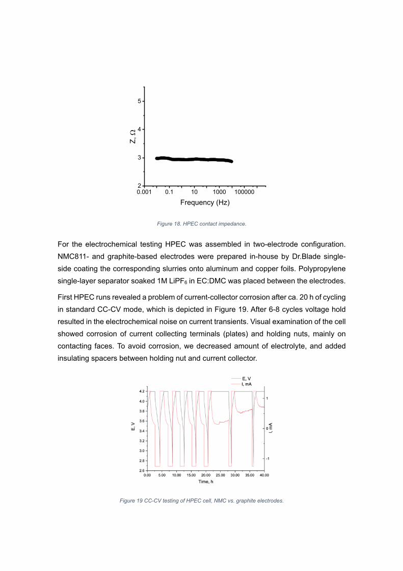
To further check the electric contacts between the electrode terminals, contact springs
and current collecting plates the impedance of the assembled HPEC cell without any
electrodes and separator was measured (Figure 18). The contact impedance magnitude
appears to be lower than 3 Ohm in the frequency range from 10 kHz to 10 mHz. Such
contact resistance is low enough for Li-ion battery cycling inside HPEC.
0.001 0.1 10 1000 1000002
3
4
5
Z,
Frequency (Hz)
Figure 18. HPEC contact impedance.
For the electrochemical testing HPEC was assembled in two-electrode configuration.
NMC811- and graphite-based electrodes were prepared in-house by Dr.Blade single-
side coating the corresponding slurries onto aluminum and copper foils. Polypropylene
single-layer separator soaked 1M LiPF6 in EC:DMC was placed between the electrodes.
First HPEC runs revealed a problem of current-collector corrosion after ca. 20 h of cycling
in standard CC-CV mode, which is depicted in Figure 19. After 6-8 cycles voltage hold
resulted in the electrochemical noise on current transients. Visual examination of the cell
showed corrosion of current collecting terminals (plates) and holding nuts, mainly on
contacting faces. To avoid corrosion, we decreased amount of electrolyte, and added
insulating spacers between holding nut and current collector.
Figure 19 СС-CV testing of HPEC cell, NMC vs. graphite electrodes.
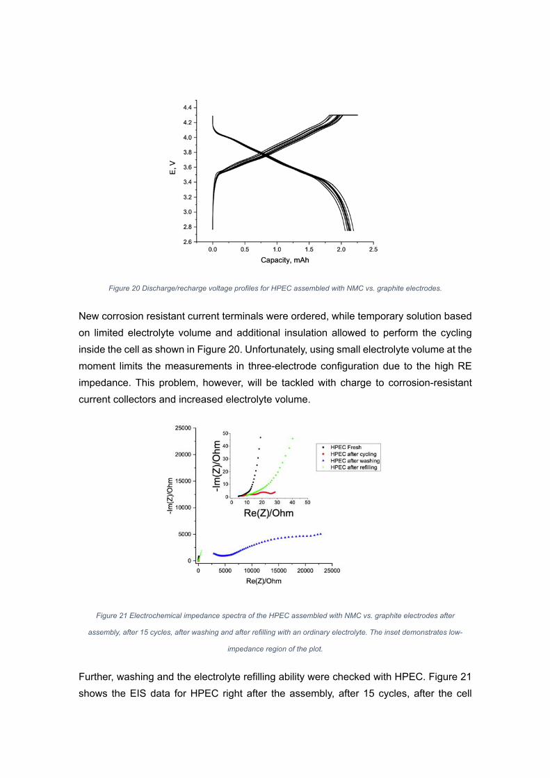
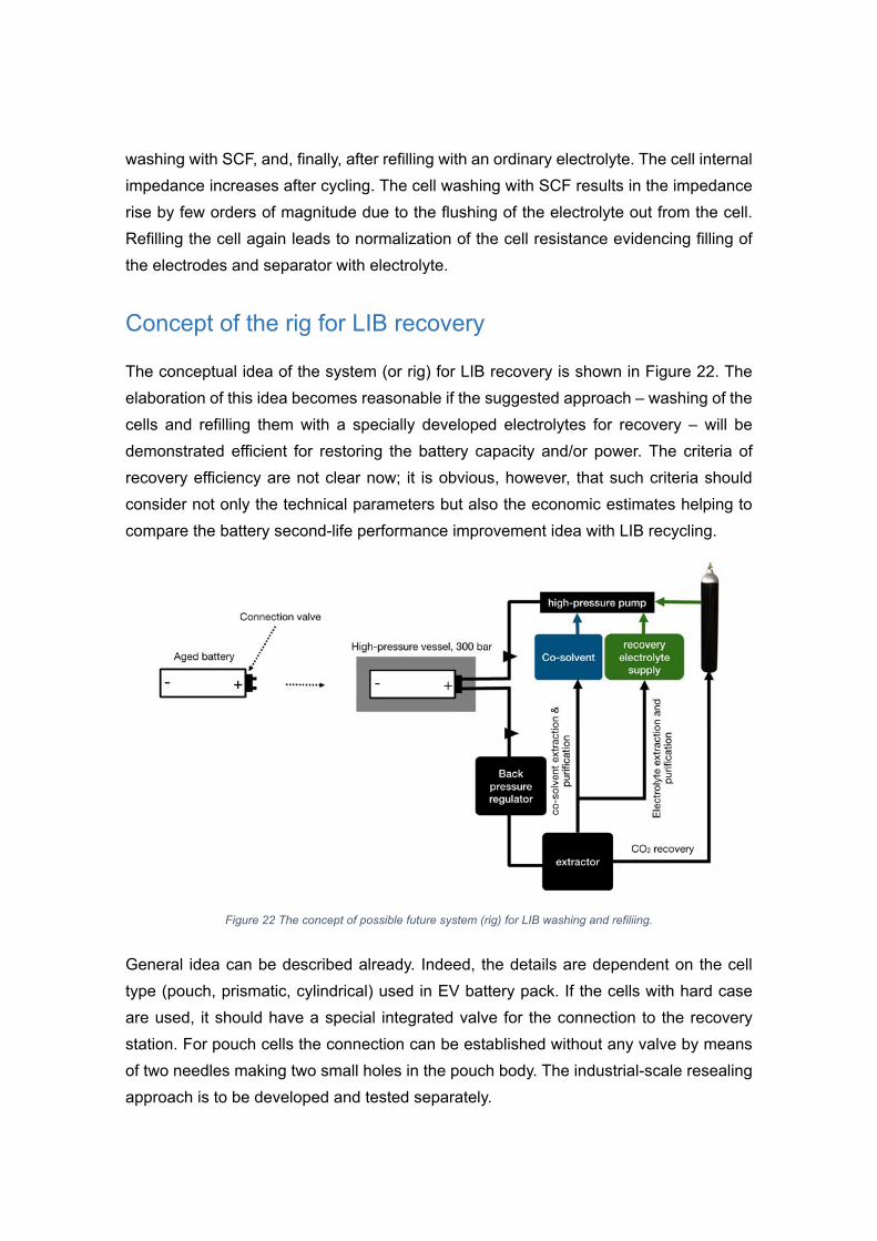
Figure 20 Discharge/recharge voltage profiles for HPEC assembled with NMC vs. graphite electrodes.
New corrosion resistant current terminals were ordered, while temporary solution based
on limited electrolyte volume and additional insulation allowed to perform the cycling
inside the cell as shown in Figure 20. Unfortunately, using small electrolyte volume at the
moment limits the measurements in three-electrode configuration due to the high RE
impedance. This problem, however, will be tackled with charge to corrosion-resistant
current collectors and increased electrolyte volume.
Figure 21 Electrochemical impedance spectra of the HPEC assembled with NMC vs. graphite electrodes after
assembly, after 15 cycles, after washing and after refilling with an ordinary electrolyte. The inset demonstrates low-
impedance region of the plot.
Further, washing and the electrolyte refilling ability were checked with HPEC. Figure 21
shows the EIS data for HPEC right after the assembly, after 15 cycles, after the cell
washing with SCF, and, finally, after refilling with an ordinary electrolyte. The cell internal
impedance increases after cycling. The cell washing with SCF results in the impedance
rise by few orders of magnitude due to the flushing of the electrolyte out from the cell.
Refilling the cell again leads to normalization of the cell resistance evidencing filling of
the electrodes and separator with electrolyte.
Concept of the rig for LIB recovery
The conceptual idea of the system (or rig) for LIB recovery is shown in Figure 22. The
elaboration of this idea becomes reasonable if the suggested approach – washing of the
cells and refilling them with a specially developed electrolytes for recovery – will be
demonstrated efficient for restoring the battery capacity and/or power. The criteria of
recovery efficiency are not clear now; it is obvious, however, that such criteria should
consider not only the technical parameters but also the economic estimates helping to
compare the battery second-life performance improvement idea with LIB recycling.
Figure 22 The concept of possible future system (rig) for LIB washing and refiliing.
General idea can be described already. Indeed, the details are dependent on the cell
type (pouch, prismatic, cylindrical) used in EV battery pack. If the cells with hard case
are used, it should have a special integrated valve for the connection to the recovery
station. For pouch cells the connection can be established without any valve by means
of two needles making two small holes in the pouch body. The industrial-scale resealing
approach is to be developed and tested separately.
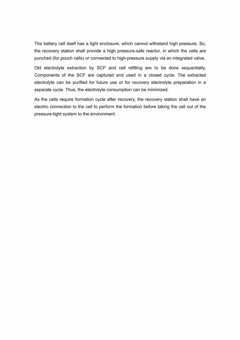
The battery cell itself has a light enclosure, which cannot withstand high pressure. So,
the recovery station shall provide a high pressure-safe reactor, in which the cells are
punched (for pouch cells) or connected to high-pressure supply via an integrated valve.
Old electrolyte extraction by SCF and cell refilling are to be done sequentially.
Components of the SCF are captured and used in a closed cycle. The extracted
electrolyte can be purified for future use or for recovery electrolyte preparation in a
separate cycle. Thus, the electrolyte consumption can be minimized.
As the cells require formation cycle after recovery, the recovery station shall have an
electric connection to the cell to perform the formation before taking the cell out of the
pressure-tight system to the environment.
Conclusions
Manual opening/“resealing” (by adhesive tape) of the pouch cells lead to
sufficient inaccuracy. Hard to check the effect of washing/recovery electrolyte
refilling.
“Resealed” pouch cells tend to degrade faster; however, refilling it with Li lactate-
containg recovery electrolyte significantly slows down the degradation. It gives a
hope that capacity will raise if experimental conditions are improved. It should be
checked in HPEC enabling more accurate experiments.
Project timeframe is not enough for proper ageing of good-quality pouch cells.
Overcharging the cells to speed up the project can lead to unpredictable results.
We need either more time, or employing express ageing techniques based on
elevated temperature.
HPEC was fabricated and tested. It is operational, nevertheless, further
improvements in design are needed. Checking the obtained results in HPEC is
already possible and ongoing.
Challenges for the future
Establishing reproducible cell ageing protocol within reasonable timeframe.
Further improvement of HPEC design and testing: extending corrosion resistance,
decreasing internal volume, testing with the reference electrode. Fabricating
more cells for speeding up the experiments.
Thorough checking all the recovery electrolyte candidate in HPEC. Reproduction
of the results for the aged pouch cells using the most successful candidates.
References
1. Sharma S.S., Manthiram A. Towards more environmentally and socially
responsible batteries // Energ Environ Sci. 2020. Vol. 13, № 11. P. 4087–4097.
2. Xu J. et al. A review of processes and technologies for the recycling of lithium-
ion secondary batteries // J Power Sources. 2008. Vol. 177, № 2. P. 512–527.
3. Zeng X., Li J., Singh N. Recycling of Spent Lithium-Ion Battery: A Critical
Review // Crit Rev Env Sci Tec. 2014. Vol. 44, № 10. P. 1129–1165.
4. Ordoñez J., Gago E.J., Girard A. Processes and technologies for the recycling
and recovery of spent lithium-ion batteries // Renewable and Sustainable Energy
Reviews. 2016. Vol. 60, № C. P. 195–205.
5. Zheng X. et al. A Mini-Review on Metal Recycling from Spent Lithium Ion
Batteries // Engineering. 2018. Vol. 4, № 3. P. 361–370.
6. Gaines L. The future of automotive lithium-ion battery recycling: Charting a
sustainable course // SUSMAT. 2014. Vol. 1–2, № C. P. 2–7.
7. Martinez-Laserna E. et al. Battery second life: Hype, hope or reality? A critical
review of the state of the art // Renew Sustain Energy Rev. 2018. Vol. 93. P. 701–
718.
8. Birkl C.R. et al. Degradation diagnostics for lithium ion cells // Journal of Power
Sources. 2017. Vol. 341, № C. P. 373–386.
9. Rumberg B. et al. Identification of Li ion battery cell aging mechanisms by half-
cell and full-cell open-circuit-voltage characteristic analysis // Journal of Energy
Storage. 2019. Vol. 25. P. 100890.
10. Elliott M. et al. Degradation of electric vehicle lithium-ion batteries in electricity
grid services // J Energy Storage. 2020. Vol. 32. P. 101873.