final report of the esa solar orbiter remote sensing payload working group
TRANSCRIPT

Final Report
ESA Solar Orbiter Remote Sensing Payload Working
Group
Richard A. Harrison (RAL, UK) & Bernhard Fleck (ESA)
June 1, 2003

Contents Summary of Recommendations to ESA Page 3 Introduction Page 5 The Approach Page 5 The Web site Page 6 The Challenges Page 7 The Challenges: Action Completion Page 12 The Challenges: Requests for ESA Support Page 94 The Payload Definition Documents (PDDs) Page 95 Final Words Page 95 Appendix 1: Integrity of Optical Components, Filters and Multilayers: Required Tests on Optical Components
Page 96
Appendix 2: Detector Development Requirements for the ESA Solar Orbiter Remote Sensing Instruments
Page 103
Appendix 3: Goals of the Solar Orbiter Page 111 Appendix 4: Instrument PDD Page 116
2

Summary of main recommendations to ESA
1 We recommend that a hard-mounted, joint pointing policy is adopted. We
believe that this is in keeping with the science goals of Orbiter and will save mass, power etc…
2 We recommend that one signal be used for image stabilisation, for all instruments that require it, and that this be provided by the VIM instrument. This will save mass and power by avoiding duplication. To avoid a single point failure, a backup option may be considered.
3 It is recommended that the ESA engineers should study a payload-wide thermal strategy rather than an instrument level strategy. This would be more elegant than having each instrument team working independently on thermal control issues.
4 It is stressed that the individual instrument thermal studies rely heavily on an understanding of the thermal inputs from the spacecraft (back of shield, conduction through mounts etc…) and such information ought to be made available even in preliminary form.
5 It is recommended that the Project study possibilities for increasing the instrument telemetry rate allocation; factors of 3-10 show significantly better scientific return. With increased on board memory (above that given in the July 2000 proposal) and more than one ground station (one was baselined in the original study), this should be feasible.
6 It is recommended urgently that the ESA Project take steps to maximise the payload mass allocation; a restricted mass allocation for instrumentation will have a direct impact on the scientific return of the mission.
7 The large thermal and particle variations of the Solar Orbiter environment require a detailed consideration of the potential degradation of optical surfaces and filters. This is considered to be an area for major study. Thus, a detailed report has been written by Schühle, Poletto and Korendyke, and is included as Appendix 1. It details required tests on optical components and has been passed to the ESTEC engineers. It is recommended that such tests be generated or supported by ESA, in preparation for the Solar Orbiter mission.
8 Since LCVR technology may be required for UVC as well as VIM, we recommend that ESA considers this technology for a study to assess and confirm its use for Solar Orbiter, and thus paving the way for future space applications.
9 Instrument co-alignment and pointing accuracy: The following are recommended by the Remote Sensing PWG: Instrument co-alignment accuracy = 2 arcminutes Absolute pointing accuracy = 2 arcminutes
10 The detector development effort is a critical issue for Solar Orbiter; this mission requires new detector technology. We recommend that ESA/ESTEC provides support to ensure that technologies applicable to several instruments are developed in a timely manner. A full report detailing the state of the detector work, the requirements for Orbiter, and the necessary developments, is given by Harrison and Hochedez, in Appendix 2. We recommend that ESA support the conclusions of that report and provide support for appropriate development work.
11 A general word of caution is given about the safety issues related to self-pointing of the spacecraft, which will occur whether target recognition is implemented or not. Note that Orbiter will be out of contact during the encounter periods. The risks of autonomous target selection and pointing must
3
be assessed fully and balanced against the obvious scientific gains. 12 It is essential that each proposed instrument provides an approach to cater for
latch up situations, i.e. there must be a capability for the instrument to monitor its state and to reboot or change mode as necessary to maintain scientific operation, without contact from the ground.
13 It is recommended that the ESTEC/ESA scientific and engineering staff concerned with Solar Orbiter, as well as the ESA SSWG and the Solar Orbiter Science Definition Team, take note of the operations scenario proposed under action 10.9.
14 The prime scientific exploitation of Solar Orbiter is centred on the encounter periods; this is an encounter mission and should be regarded as such. It is recommended that the non-encounter periods be used for operations testing (in preparation for encounter), for calibration and test activities, but possibly for limited scientific measurements.
15 A 150 day planning cycle is appropriate. The 30 day encounters should consist of a set of pre-programmed, autonomous Joint Observing Programmes (JOPs), scheduled in response to a formal call for proposals and selection procedure with the PI teams, for each encounter. An appropriate schedule of planning meetings can be set up each orbit to test sequences and finalise plans prior to each encounter.
16 It is most appropriate to have a dedicated Solar Orbiter operations facility, housing the flight operations activities, but with facilities for instrument teams to plan and operate test and calibration activities, and to uplink commands for the upcoming encounters, and to be used for mission planning and health monitoring.
17 Intelligent operation, through the use of flags and possible operational and pointing changes to cater for specific solar targets/events should be studied to enhance the scientific return of the mission. However, the risks involved must be studied closely.
18 We have identified for illustration just a few possible event types, such as SEUs, particle events, thermal anomalies etc…, which could require evasive action by the instruments. They illustrate that (a) we must build in schemes for recognising problems, and (b) we must be able to respond to them - all without ground contract. It stresses that each instrument team must define a basic 'safe mode' and must list possible dangerous events and suggested responses at the time of proposal. Note that some of these activities suggest options where information is exchanged between instruments.
19 The Solar Orbiter Science Definition Team, as well as the ESA SSD and SSWG, are invited to take note of the PWG study on Solar Orbiter science goals, to be produced by Alan Gabriel.
4

Introduction The ESA Solar Orbiter Payload Working Group (PWG) was set up after a Call for Letters of Interest in late 2001. The aim of the PWG was to assess the strawman payload feasibility (in particular due to the mission extreme environmental conditions) and to provide technical information in preparation for the Solar Orbiter industrial study. The PWG was divided into Remote Sensing and In-Situ components and this report is the outcome of the deliberations of the Remote Sensing PWG. The members of the Remote Sensing PWG are listed below. R.A. Harrison (CO-CHAIR) Rutherford Appleton Laboratory UK B. Fleck (CO-CHAIR) ESTEC ESA R. Bush Stanford University USA J.-M. Defise Centre Spatial de Liege Belgium S. Fineschi Torino University Italy A. Gabriel Inst. Astrophys. Spatiale, Orsay France A. Gandorfer Max-Planck-Inst. für Aeronomie, Lindau Germany L.K. Harra Mullard Space Science Laboratory UK D.M. Hassler Southwest Research Inst., Boulder USA J.-F. Hochedez Royal Observatory, Brussels Belgium C. Korendyke Naval Research Lab., Washington USA P. Lamy Marseille France R. Lin Berkeley University USA V. Martinez-Pillet Inst. de Astrofisica de Canarias, Tenerife Spain L. Poletto Padua University Italy I. Rüedi World Radiation Centre, Davos Switzerland U. Schühle Max-Planck-Inst. für Aeronomie, Lindau Germany M. Sigwarth Kiepenheuer Inst. für Sonnenphysik,
Freiburg Germany
The ESA/ESTEC technical representative is Thierry Appourchaux. The PWG met at ESTEC on May 16/17 2002 and November 25/26 2002, though most studies and actions were performed between May 2002 and May 2003 at home institutes with communication by e-mail and through a dedicated Web site. The Approach The tasks of the PWG can be split into three main areas: To identify the technical challenges of the mission/instruments and assess the
feasibility of achieving them; To identify outstanding areas needing technical development or study, possibly
with the support of ESA; To provide expertise in the development of instrument details, through the so-
called Payload Definition Documents (PDDs), as input to the industrial study. Thus, the Remote Sensing PWG agreed to the following method, at its first meeting: To identify all challenging areas where there was a need to demonstrate
feasibility, either from a mission or instrument point of view; To list these challenges and assign them as actions to members of the PWG for
assessment and study outside the meeting;
5

To complete reports on each challenge (action completion reports) - these reports to form part of the final report of the Working Group;
To identify any areas where further studies or test activities would be required, possibly with support from ESA, and to make appropriate recommendations;
In addition, PWG members to be selected to represent the different strawman instruments to co-ordinate the construction of Payload Definition Documents (PDDs) for each instrument, in collaboration with the ESTEC technical team.
Throughout the report, recommendations are made, which are highlighted in bold, red italics, and boxed. These must be noted in future studies. They are summarised in the table after the contents page. The Web Site A Web site was set up at http://www.orbiter.rl.ac.uk/solarorb/rspwg/ to co-ordinate the Working Group discussion and reports. The front page is shown below.
6

Notes/presentations from the two meetings are included under the 'Documents' section and the link to 'Other Documents' provides a library of related documents, set up by Bernhard Fleck. The link labelled 'List of Actions' is the master-list of identified challenges which was constructed after the first meeting. This list is discussed in the next section. The link, 'Action Status Documents' includes an Excel file, which tracks the status of each action (shown in detail below) and contained the action completion reports prior to compilation of this report. The Challenges Our first task was to list the challenges, i.e. those items that must be addressed to demonstrate feasibility of an instrument or of the mission. The challenges are listed by strawman instrument. Some are common to several instruments and are listed in the first section. All of the challenges discussed by the Working Group were classified, using the following categories: Category (I): ‘Global’ (mission/operational) challenges (e.g. pointing); Category (ii): Multi-instrument challenges (e.g. detectors); Category (iii): Instrument-specific challenges which are potential show-stoppers; Category (iv): Other instrument-specific challenges.
We did not consider Category (iv) items as being relevant for the discussion of the Working Group (this is for the proposing teams!) and do not list them below. We acted upon all of the others. It must be noted that the prime objective is to demonstrate feasibility, i.e. we do not need to design the instruments, just demonstrate that such instruments could operate effectively within the Solar Orbiter mission. The Solar Orbiter Remote Sensing strawman instruments are: VIM Visible Light Imager and Magnetograph EUS EUV Imaging Spectrometer EUI EUV Imager UVC UV and Visible Coronagraph RAD Radiometer (HEI) (High Energy Imager) (HI) (Heliospheric Imager) The instruments in brackets were not part of the prime strawman instrument list, but were considered and mentioned as possible instruments in the July 2000 proposal. Thus, they are considered here. Note that for the HEI instrument, we use the so-called STIX instrument concept. We now list the challenges identified by the PWG. The numbers allotted to each challenge are the action numbers used in the study.
7

1. Challenges Relevant to All Instruments 1.1 - A thorough study of the thermal feasibility of each instrument is required, probably including modelling and test activities in some cases. In particular, it must assess the thermal balance, the impact of the orbital variations to the thermal input and the impact of (and ways to cope with) degradation/aging of the reflectivity of the optical systems. An estimate of the radiator size requirements must be made. Category (iii). 1.2 - The thermal ‘regulation’, during the orbit, of each instrument must be considered, for example, using regulating radiators (e.g. cut/limit the radiators at/near aphelion) or switchable heat-pipes, to damp the extremes in the variability. This must be studied to demonstrate that we can cope with a heat load varying by a factor of 25. Category (iii). 1.3 - A realistic study is required to show that the scientific operation of each instrument is not compromised by the limited telemetry rate. Category (iii). 1.4 - A realistic study of the mass of each instrument is required. Category (iii). 1.5 - A realistic study of the power for each instrument is required. Category (iii). 1.6 - A study of the radiation degradation of filters and multilayers and related thermal aging must be performed. Some instruments will use filters or multilayer coatings to reduce the solar flux. In addition to the thermal load, the radiation dose will lead to degradation, contamination and particle implantation. The change in thermal properties, for example, induced by this must not compromise the thermal balance of the instruments. Category (ii). 2. Additional Challenges Unique to VIM 2.1 - Can the proposed camera system cope with the perceived particle environment? Is a visible APS detector a more realistic solution? See detector section below. Category (ii). 2.2 - Can we demonstrate that electro-optically modulated liquid crystal devices are not influenced by the particle and thermal environment? Can we specify the UV radiation shielding needed by these liquid crystal retarders? Category (ii). [with UVC]. 2.3 - VIM carries a sensor used for image stabilisation. It is suggested (below) that this be used as the image stabilisation signal for all instruments requiring stabilisation – to save mass by avoiding duplication. While a preference for a limb sensor is identified, it needs to be proven whether a full correlation tracker is (scientifically) needed to provide the error signals for the tip-tilt mirrors. Category (I). 2.4 - For the thermal and particle extremes, which Orbiter will encounter, how do we guarantee the required levels of cleanliness in VIM? Category (ii). 2.5 - What coatings can be used for a hot SiC primary mirror? How do these coatings behave with time (reflectivity) under 0.2 AU conditions? What solutions for a field-stop in an open VIM are feasible? What radiators are needed? Category (iii)
8

2.6 - Is it feasible to include a front filter on VIM? What materials could be used and what are the size and mass limitations on this solution? Category (iii). 3. Additional Challenges Unique to EUS 3.1 - The question of contamination and subsequent degradation of the optical systems must be considered, especially in the extreme thermal and particle environment. Consider tests which could be performed as well as outgassing policies etc… Category (ii). 3.2 - If we remove the independent pointing capability, can we include a method for image alignment? This is a general question for several instruments to ensure co-pointing. Category (ii). 3.3 - Can we assess the integrity of multilayers at high temperatures including a definition of tests to be done. Category (ii). 3.4 - Can we demonstrate that 5 micron 4kx4k APS, visibly blind detector systems are likely to be possible for such an instrument? Category (iii) but see detector section below. 3.5 - There is some concern over the impact of the particle environment on optical coatings in the light of studies of hydrogen bubbles forming under gold coatings in the solar wind. This must be assessed. Category (ii). 3.6 - The strawman EUS of the July 2000 proposal is too long (compared to the payload module). Can we demonstrate that a shorter instrument is possible. Category (iii). 4. Additional Challenges Unique to EUI 4.1 - The proposed EUI (July 2000 proposal) is long (2.5 m), compared to the payload module. Can Solar Orbiter accommodate this or do we need to demonstrate that a shorter instrument is feasible? Category (iii). 4.2 - We must assess the most realistic detector option given the particle environment. See detector discussion below. Category (ii). 4.3 - If we remove the independent pointing capability, can we include a method for image alignment? This is a general question for several instruments to ensure co-pointing. Category (ii). 5. Additional Challenges Unique to UVC 5.1 - If there is a common pointing policy, UVC must be able to cope with likely offsets. Assess this. Category (iii). 5.2 - We must assess the integrity of the liquid crystal device in the particle/thermal environment. Category (ii) [with VIM]. 5.3 - The instrument will most likely include multilayers and, thus, a consideration and test of multilayers at high temperatures is required. See EUS. Category (ii).
9

5.4 - The best options for detectors must be assessed, given the particle environment. See detector discussion below. Category (ii). 6. Additional Challenges Unique to RAD The principal issues of mass, power, telemetry are dealt with above. The particular needs of RAD are - The precision of temperature control and temperature levels must be assessed. - The cavity aging due to a higher solar constant must be studied. - The feasibility of keeping to an accuracy of 0.01% throughout mission must be studied. However, these are really category (iv) concerns and are not considered further here. 7. Additional Challenges Unique to HI Again, the principal issues of mass, power and telemetry, and thermal control, are covered above and there are no further issues raised at this time. 8. Additional Challenges Unique to HXI The STIX instrument has been used as a model for this (see PDD) and, beyond the major issues of power, mass, telemetry and thermal control, only the detector is raised as an issue. This is covered below. 9. General Challenges for the Spacecraft Study 9.1 - Can the possibilities for a payload mass increase be studied? Category (ii). 9.2 - Can the possibilities for a payload telemetry increase be studied? Category (ii). 9.3 - Can the possibilities for a payload power increase be studied? Category (ii). 10. General Mission/Spacecraft/Operational/Multi-instrument Challenges Pointing: It is proposed that the instruments are hard-mounted to the spacecraft and that we have a co-pointing policy. This is in keeping with a co-ordinated Joint Observing Programme (JOP) operations scenario. It is recognised that this would save mass, power and will simplify operations. 10.1 - We must assess the impact of such a policy on UVC – how do we compensate for this? UVC will need some adjustment. Category (iii). 10.2 - We must study how to deal with co-alignment – a method is required to ensure that we have aligned fields. Does this simply require large areas or some mechanisms? Category (I).
10

We recommend that a hard-mounted, joint pointing policy is adopted. We believe that this is in keeping with the science goals of Orbiter and will save mass, power etc… Detectors: It is recognised that we must demonstrate feasibility, rather than select the ‘final’ detector system. It is noted that the demands on small pixels (down to 5 microns), array sizes (up to 4kx4k), mass, and the particle environment may be very restricting to CCD systems and this suggests that APS and Diamond detectors are appropriate. The different advantages of these two are noted but some areas require study, assessments and tests. 10.3 - We must study the detector options, taking into account the Orbiter requirements and environment. Does this require some technological activity funded by ESA? Category (ii). Note that our original item 10.4 has been removed because it was incorporated into 10.3. 10.5 - Can we characterise the expected particle environment at 0.2 AU, including solar wind flux, flare/CME/shock accelerated particles, cosmic rays and neutrons? In particular, the anticipated neutron environment is of concern. Assess the impact of this on the APS and Diamond systems. Category (ii). Image Stabilisation: 10.6 - It is noted that an image stabilisation system is required and, to save mass, it is best to use a signal from only one source, e.g. the VIM. We must assess this option fully. Category (ii). We recommend that one signal be used for image stabilisation, for all instruments that require it, and that this be provided by the VIM instrument. This will save mass by avoiding duplication. To avoid a single point failure, a backup option may be considered. On-board Intelligent Operation: We must assess whether or not we want to have on-board target recognition for autonomous target selection. Note that this will most likely drive pointing of the spacecraft (given above recommendation of fixed mounting of instruments). 10.7 - We must initiate a target recognition, automated pointing study to assess fully how we cope with this for Orbiter. List what targets could be selected and the responses. What timing constraints exist for what targets? What mode changes could be envisaged? This will require image/data on board inspection and reaction. Category (I). 10.8 - Autonomous operation of the instruments must be guaranteed, despite the likelihood of latch-ups due to the local particle environment. An instrument failure due to a latch-up, which would be undetected and uncorrected during a solar pass, would result in a substantial loss to the science. Latch-up detection and automated
11

scientific operation resumption must be incorporated. Options to manage such situations at instrument and spacecraft level must be assessed. Category (I). Operations Planning: We must treat the mission as an encounter mission with a 149-day planning cycle. Organisation of the encounter periods will be done using JOP selections for the passes. Selection of some targets can be done well ahead of time and updated nearer to each pass. Some targets need intelligent selection. 10.9 - Assess the operations scenario based on this encounter mission scenario? Category (I). Instrument Safing: 10.10 - We must study the hazards for each instrument and how the instrument should respond? This should include an assessment of transferring data to warn other instruments that do not have access to such data (e.g. warning UVC of a flare). It should include a consideration of the thermal impact of closing doors. Category (ii). 11. Scientific Objectives Finally, it has been noted that the scientific goals of Solar Orbiter are rather poorly defined. The four new aspects of the mission, i.e. close solar encounter, out of ecliptic observation, co-rotation and inner heliosphere sampling, open up exciting new scientific opportunities, but the refined scientific goals are required to allow the best tuning of the instrument and operation designs. Thus, we add a further study. 11.1 - We must assess the scientific goals of the mission. Category (I). This last item is rather different from the rest and is discussed later. The Challenges: Action Completion The challenges, numbered above, were listed in the Excel spreadsheet on the Web site and assigned as actions for study by the members of the PWG. The first five columns of the spreadsheet as of 1 June 2003 are copied below. The table shows the status of each action/study at that date. Solar Orbiter Remote Sensing Payload Working Group Study Matrix
Version: 1 June 2003 Action Category Sub-
Action Lead Person Status
1.1 Thermal Feasibility Study
iii EUS Harrison/Harra Closed
iii EUI Harra/Defise/Hassler Closed iii UVC Fineschi Closed
iii VIM Sigwarth/Gandorfer Closed iii RAD Ruedi Closed iii STIX Lin/Hurford Closed
12

iii HI Korendyke Closed 1.2 Thermal Regulation iii EUS Harrison/Harra Closed
iii EUI Defise/Hassler/Harra Closed iii UVC Fineschi Closed
iii VIM Sigwarth/Gandorfer Closed iii RAD Ruedi Closed iii STIX Lin/Hurford Closed iii HI Korendyke Closed
1.3 Telemetry iii EUS Harrison Closed iii EUI Hochedez/Hassler Closed iii UVC Fineschi Closed
iii VIM Martinez Pillet Closed iii RAD Ruedi Closed iii STIX Lin/Hurford Closed iii HI Korendyke Closed
1.4 Mass iii EUS Harrison Closed iii EUI Defise/Hassler/Harra Closed iii UVC Fineschi Closed
iii VIM Martinez Pillet Closed iii RAD Ruedi Closed iii STIX Lin/Hurford Closed iii HI Korendyke Closed
1.5 Power iii EUS Harrison Closed iii EUI Defise/Hassler/Harra Closed iii UVC Fineschi Closed
iii VIM Martinez Pillet Closed iii RAD Ruedi Closed iii STIX Lin/Hurford Closed iii HI Korendyke Closed
1.6 Filter/Multilayer/optical surface degradation
ii Schuehle/Poletto/Korendyke
Closed
2.1 VIM detectors ii See 10.3 Closed 2.2 VIM LCD & environment
ii Martinez Pillet Closed
2.3 VIM stabilisation sensor
i Martinez Pillet Closed
2.4 VIM cleanliness ii Schühle/Gandorfer Closed 2.5 VIM coating study ii See 1.6 Closed 2.6 VIM filter ii Gandorfer Closed 3.1 EUS contamination/degradation
ii Poletto/Harrison/Schühle
Closed
3.2 EUS image alignment ii Harrison Closed 3.3 EUS multilayer integrity ii See 1.6 Closed 3.4 EUS detector option iii See 10.3 Closed 3.5 EUS particle impact study
ii Harrison Closed
3.6 EUS length iii Harrison/Poletto Closed 4.1 EUI length iii Defise Closed 4.2 EUI detector ii See 10.3 Closed
13

4.3 EUI image alignment ii Covered by 3.2 Closed 5.1 UVC pointing offsets iii Fineschi Closed 5.2 UVC LCD integrity ii See 2.2 Closed 5.3 UVC multilayer integrity
ii See 1.6 Closed
5.4 UVC detector ii See 10.3 Closed 10.1 Pointing - UVC impact iii Covered by 5.1 Closed 10.2 Pointing - alignment I See 3.2 Closed 10.3 Detectors - Requirements
ii Schühle/Hochedez/Poletto/Harrison
Closed
10.5 Detectors - Particle Environ.
Ii Covered by 10.3 Closed
10.6 Stabilisation - VIM source
ii Martinez Pillet/Hochedez
Closed
10.7 Operation - target recog.
i Harra/Hochedez Closed
10.8 Operation - latch up i Harrison Closed 10.9 Operation - planning i Harrison/Harra/Hoched
ez/Fleck Closed
10.10 Instrument Safing ii Harrison Closed 11.1 Scientific Objectives A. Gabriel On-
going For most actions, the standard approach was the completion of an Action Completion Form and these are reproduced below, with modest editing, for the completed actions. Note again, that major conclusions or recommendations that are particularly important, i.e. those that must be well understood from this point, are highlighted in red in the relevant reports. It should be noted that the idea is to study each topic to address feasibility. There will still be open questions about instrument detail and some outstanding issues (some of which are highlighted in the text by the editors), but the most basic demonstration of feasibility is the aim here. We cannot answer every question at this stage, but we can ensure that we are all comfortable that a mission with a payload like that of the strawman payload can work. The nature of the exercise means that the following reports are rather non-uniform in their approach, and some have been combined (as shown in column 4 of the Table above). Some reports which contain lengthy analyses are referred to and can be found in full at the Web site. Action ID Number: 1.1 - EUS & 1.2 - EUS Responsible Working Group Member: Richard Harrison & Louise Harra Action: Thermal feasibility study for EUS instrument/Adaptive Optics This report covers two areas. First we discuss the basic outcome of thermal studies for EUS design concepts. Second, recognising the variable thermal loads we discuss the possible use of adaptive optics. EUS Thermal Study: A preliminary thermal study has been performed of two proposed designs for the EUS. This has been done at RAL by a Cranfield University MSc student (Mattieu
14
Gasquet) working closely with the RAL solar group (see reference). The two designs include: (1) an off-axis normal incidence (NI; off-axis Ritchey-Chretien) design with 120 mm aperture (due to Martin Caldwell, RAL), and (2) a 35x35 mm aperture stigmatic grazing incidence (GI) Wolter II design (due to Luca Poletto, Padua). Both systems use a variable line spaced grating in normal incidence. The optical discussion is not included here. However, both designs are representative of the kind of design that an EUS instrument might adopt, and are sufficient for thermal considerations. To tackle the thermal situation it was assumed that a radiator area up to the size of the instrument footprint may be used. Various surface coatings were considered. For the NI design, the off-axis design allows a significant heat stop (reflecting a significant amount of energy out of the front aperture) between primary and secondary; thus, the critical area to consider is the heat load on the primary. The Wolter II design uses grazing incidence optics and, thus, a reduced aperture, which makes the thermal load much more manageable. The heat loads on the primary mirrors for the two designs are 41 W and 380 W for the Wolter II and the NI design, respectively. Refer to Gasquet (2002; see reference list) for the full analysis. However, for comparison let us examine a steady state situation at 0.2 AU, and fix the mirror temperature at 610 and the radiator temperature at 500. For various mirror coatings for the Wolter II option (e.g. gold, platinum, silicon-carbon) the radiator size required ranged from 0.0313 to 0.0935 m2. The instrument footprint might be of order 0.3 to 0.5 m2. Similarly, for the NI design, the radiator size ranged from 0.51 to 0.92 m2. These figures assume some absorption from the back of the spacecraft heat-shield (because it extends beyond the edge of the payload module). The NI figures, for example, come down by a factor of up to three if this is negligible. Thus, for this static 0.2 AU case, the Wolter II design is feasible and the off-axis NI design is borderline, but feasible for certain materials if the absorption from the heat-shield is not severe. The off-axis design is clearly more challenging and was considered using a time dependent model, which mimics the orbit. This model showed that the primary mirror temperature varies considerably during the orbit. The absolute temperatures could be controlled to some extent by using different mirror coatings, different heat-shield parameters, different radiator sizes and conductivities. However, considerable temperature variations were found over the orbit, e.g. the orbital temperature variation of the primary mirror ranged from 1000 to –500 C for one case, 1800 to 00 C, and 310 to –1200 C for others. A full range of 1500 is typical over the half-orbit period. This large temperature variation is a serious issue, which is most likely of concern for many of the instruments. Preliminary considerations of a heat-switch to the radiator show that some reduction is possible in the extreme ranges, but we are still looking at a significant range in temperature and a rather spiky temperature profile. This could be brought down and smoothed by a more sophisticated heat-switch arrangement, heaters and a better optimisation of the thermal design. However, the current studies suggest that the thermal variations present a severe problem for a NI design. From a feasibility point of view, given the much reduced heat load, the GI approach can be used to confirm that an EUV spectrometer will operate aboard the Solar Orbiter mission, but it is clear that any NI design must have a clear demonstration of thermal control at the time of the AO.
15
It should be stressed that the current study has concentrated on the optical components and the temperature of the structure is of paramount importance. Further improvements could be made from a spacecraft wide strategy, e.g. radiator viewing directions, heat shield absorption minimisation, spacecraft/payload wide cooling rather than instrument level cooling strategy etc… New Technologies: Adaptive Optics One approach to cope with some aspects of the thermal situation, which will be encountered by Solar Orbiter is the use of adaptive optics. The Smart Optics Faraday Partnership in the UK is investigating this and a number of areas have the potential for being used in space. Solar Orbiter will be in such an extreme environment that it seems to be an ideal candidate for such systems. For example, mass savings can be achieved from relaxation of the mechanical constraints imposed by the requirement to align complex optical systems prior to launch, by use of smart optics to correct for alignment errors in a lightweight optical system post-launch. Savings can also be obtained by relaxing constraints on the thermal design, by using adaptive optics to correct for thermally introduced optical aberrations in-flight. Applicable technologies for Solar Orbiter might be: • Aluminium mirrors: robust and easy to control thermally—possibly as part of an
isothermal design where the physical relationships between the optical components are self-correcting; Aluminium has been predominately used in infrared and X-ray space telescopes, but there has been little use of aluminium for optical ground or space based telescopes. Aluminium mirrors were considered for the VLT primaries and prototype mirrors were made (by REOSC) that were within the specs, though glass was eventually chosen;
• Deformable mirrors: another method of controlling the focus and image quality.
Not only can these mirrors be lighter than monolithic types they can also represent an overall system improvement when considered as part of an adaptable structure. A diagram showing a typical system is shown in the figure. It is very important to notice here that the closed-loop bandwidth requirements for a self-focussing system in the Solar Orbiter are trivial compared with the performance required to achieve real-time correction of atmospheric distortions in terrestrial telescopes. Atmospheric adaptive optics systems have an update rate of ~1000 Hz (giving closed loop bandwidth of ~100Hz). An active optics system for space (primary mirror support system for example) can work very much slower, at 0.1-10Hz perhaps. Various types of deformable mirror are currently available such as thin ceramics controlled by piezo-actuators, bimorph mirrors (two sheets of piezo electric material), and thin membrane electrostatically deformable mirrors. For the Solar Orbiter however, a metallic (perhaps aluminium) deformable mirror controlled by actuators would probably be preferable due to its high thermal conductance which allows heat to be conducted away easily and limits thermal distortions to large spatial frequencies, mainly defocus, which can be corrected by its adaptive nature. For the Solar Orbiter the number of actuators would probably be quite low (10–20) as the only low spatial frequencies would have to be corrected. Various low-precision actuators have already been used in space, but less work has been done so far on the high precision actuators likely to be needed for Solar Orbiter. Work is ongoing in this area. However, for example, the high accuracy position actuators by Energen Inc.
16

are low power, light weight and capable of cryogenic operation; there would also need to be some sort of wavefront sensing in the system to measure the mirror distortion and provide feedback to the mirror. This could be achieved with a separate wavefront sensor or the science detector alone. The diagram shows a typical layout of the components used for correction of atmospheric turbulence. In this configuration a share of the incoming light is picked off and distortions in the wave front are measured by the wave front sensor, typically with reference to a guide star. The processor system can then calculate the correction that is needed in the optical path and the necessary shape is applied on the deformable mirror.
• Thermochromic Coatings: Scaling a radiator to keep a primary mirror cool enough during perihelion is likely to lead to too great an oscillation in temperature as the spacecraft progresses around its orbit. A thermochromic surface that can vary its emittance would solve this problem with no moving parts or control systems necessary.
“Classical” Adaptive Optics System
With regard to the adaptive optics concept, the precise requirements need to be considered in detail by any proposing instrument team. The inclusion of the concept here does not necessarily imply that this approach can provide the mass saving or the necessary responses (in time and space) required for any particular design. This needs to be studied, and is being considered by the UK-led consortium considering an EUS proposal. Another option for any thermal design is that the optical integrity must be maintained for the prime mission, i.e. the encounters, and it may not be necessary to maintain the same level of optical quality outside the encounter periods. This
17

allows us to accept some flexing of the instruments without the need for full-time control. Conclusion: 1. Two EUS designs were considered which are representative of the design
concepts we anticipate for the EUS instrument. We believe that a grazing incidence design option is feasible from a thermal point of view, but an off-axis NI design requires considerable work to demonstrate thermal feasibility.
2. Further work is to be done on both options, including a full consideration of the use of heat-switches, heaters etc… and extending the analysis to include a complete temperature profile of the structure in particular.
3. Further work does depend on some spacecraft level input. What absorption can we expect from the back of the heat-shield, by radiation or even by conduction at the front of the instrument? What is the maximum size of the EUS radiator?
4. Given the extreme thermal situation, it is sensible to embark on a study of thermal control options for the payload at a spacecraft level. We recommend this. For example, can we de-couple the heat-shield as much as possible from the instrument front bulkheads and is it possible to minimise radiation from the heat-shield to the instrument radiators? Is the spacecraft shape best suited to a system with multiple radiators facing space? Would it be sensible to consider a payload-wide heat-pipe cooling system?
5. Proposing teams should consider the feasibility of using adaptive systems for Solar Orbiter, e.g. deformable mirrors and thermo-chromatic mirrors. However, the optical systems may be tuned to the encounter periods, allowing teams to relax the control during the non-encounter periods, i.e. the optical integrity need not be maintained accurately throughout the entire orbit.
It is recommended that the ESTEC engineers should study a payload-wide thermal strategy rather than an instrument level strategy. This would be more elegant than having each instrument team working independently on thermal control issues. It is stressed that the individual instrument thermal studies rely heavily on an understanding of the thermal inputs from the spacecraft (back of shield, conduction through mounts etc…) and such information ought to be made available even in preliminary form. References: 1. Gasquet, M., 2002, Cranfield University MSc Research Report, ‘Solar Orbiter: Thermal Analysis and Design of an Extreme Ultraviolet Spectrometer’. (see Web site http://www.orbiter.rl.ac.uk/solarorb/rspwg/actions/ file gasquet_report.pdf). 2. Smart Optics Faraday partnership – http://www.smartoptics.org. Action ID Number: 1.1 - EUI & 1.2 - EUI Responsible Working Group Member: Louise Harra, Jean-Marc
Defise & Don Hassler Action: Thermal feasibility study for EUI instrument This report assesses the thermal situation for the proposed Full Sun Imager component of the EUI strawman instrument. The work is detailed in an MSSL study
18
report by P.H. Sheather (15 December 2002) (found at the Working Group Web site http://www.orbiter.rl.ac.uk/solarorb/rspwg/actions/ as file sheather_report.doc). The MSSL report describes a simple thermal model, developed to represent the FSI instrument. At the time of construction of the thermal model, no satisfactory and definitive boundary condition data for the model was available. The model was therefore designed to give flexibility to change the boundary conditions at a later time. Two boundaries were defined. The first was the spacecraft in general and was set to 200 C, and the second was space at –2730 C. The original model of the instrument consists of 10 isothermal nodes representing its external surfaces Additionally, an internal baffle, the two mirrors, the detector, the thermal filter, and two structure panels were represented by a further 7 internal isothermal nodes. A radiator of 0.25 m2 is located externally. Electrical power input was modelled as being uniformly distributed over the volume representing the detector electronics with a nominal value of 10 W. The first model used, called FSI1, represents the instrument design as it was previously presented. While constructing this model, and attempting to represent the solar energy input, it became apparent that the baffle seemed to have no thermal benefits. In fact it seemed to be a serious handicap, and it is not clear that there is any scientific purpose either. The instrument is designed to face towards the Sun’s disk at a minimum range of 0.2 AU, and the incident radiation will then be about 35 kW/m2. The acceptance angle of the baffle appears to be about 5 degrees, and the angle subtended by the Sun’s disk will be about 2.5 degrees. The thermal filter in the basic design will therefore be exposed to full intensity solar radiation, and the baffle apparently provides no attenuation. In fact, because of the angular width of the solar disk, most of the baffle sides will also be illuminated to some extent, although not at full intensity. What can be said for certain is that over 500 W will pass through the entrance aperture, and whatever the internal absorptivities, most of that will heat the baffle by multiple reflection and absorption. A small fraction will escape, but as a worst case it has been assumed that it all heats the baffle. The thermal filter then has to radiate its heat to a very hot baffle. Two further models have therefore been created which simulate proposals that overcome some of these problems. The first is called FSIFF1 (FF for Filter Forward), and the only change is to represent the thermal filter at the entrance opening of the baffle, rather than between the baffle and the telescope. It has the clear advantages that no solar energy enters the instrument directly, the thermal filter is free to radiate to space, will therefore operate cooler and it is located further from the telescope. The disadvantage is that the thermal filter is larger in diameter and will be more difficult to support. The second alternative model called FSINB1 (NB for No Baffle) represents the total removal of the baffle, leaving the thermal filter in its original location. The advantages of this are that the filter is again free to radiate to space and therefore runs cooler, and that the instrument is more compact. The filter also retains its original diameter. The hot filter is however closer to the telescope components, and will have a greater heating effect on them than in the above case.
19
Finally the last model was changed to FSINB2, in which the absorptivity, emissivity ratio of the outside of the thermal filter was changed to 0.3/0.8 to represent the use of a second surface mirror system. Results: The results from the models are as follows:- As expected, for the original configuration, model FSI1, the baffle ran rather hot at about 132 C, and as a result the thermal filter was at 470 C. The telescope and its components were at about 40 C to 60 C. This was clearly less than satisfactory. For model FSIFF, with no baffle in front of the thermal filter to obstruct its view of space, its temperature dropped to 444 C, and the baffle to 25 C. The telescope area and the optical components had temperatures in the range 19 C to 21 C. This represented a considerable improvement. For the model FSINB1, with the filter in its original location and no baffle, the thermal filter now ran at 455 C, and because of its proximity to the telescope, this and its optical components were now in the range 20 C to 22 C. The instrument is however much more compact , and the thermal penalty for this is not great. For model FSINB2, the thermal filter now operated cooler at 403 C, with no significant change to the telescope temperatures. This is clearly a way to reduce the filter temperature, if a suitable surface treatment with high temperature resistance can be found. Conclusions and recommendations: The major object of the modelling was to provide a representation of the FSI in the Solar Orbiter thermal model. This has been achieved, with three alternative models. It should be noted that if any internal data is to be gleaned from these models, they need to be reviewed in detail for the areas in question. It is fairly clear that the original baffle design did not appear to deal well with the high incident solar radiation, and some more thought needs to be given to this aspect of the design. The second and third models illustrate two methods of improving the situation. It is also suggested that the performance of the thermal filter could be enhanced by changing its solar facing surface from a first surface mirror to a second surface mirror. This is demonstated in a fourth model. This could be achieved by coating this surface with a few microns of polymer such as Teflon. The coating thickness is critical, but an absorptivity/emissivity ratio of 0.3/0.8 should be achievable by this means, which would dramatically reduce the thermal filter temperature. The production of such a component should be carried out by a specialist, and could be very expensive. The problem of atomic oxygen erosion would also have to be investigated for the proposed orbital conditions. [Note added by editors: In keeping with the results of the EUS study, it would be prudent to extend the thermal considerations to an analysis of the thermal changes during the orbit, and to design a strategy to minimise the impact of those changes on the instrument. This remains TBD for EUI, but the essential problems are the
20

same for all instruments and in the case of the EUV instruments, is of more concern for the EUS, which has a larger aperture. See above.] Reference: Sheather, P.H., 2002, Report on the Thermal Modelling of the FSI Instrument, see http://www.orbiter.rl.ac.uk/solarorb/rspwg/actions/ as file sheather_report.doc. Action ID Number: 1.1 - UVC & 1.2 - UVC Responsible Working Group Member: Silvano Fineschi Action: Thermal feasibility study for the UVC instrument The optical configuration of the Ultraviolet and Visible-light Coronagraph (UVC) included in the Solar Orbiter Assessment Study Report (Marsch and Study Team , 2000) has been described in detail by Antonucci, Fineschi, et al. (2000). The UVC optical design has evolved since the original baseline design was studied (Fineschi et al., 2001). The new configurations include a sun-disk rejection mirror besides the external occulter of the baseline design. This study, therefore, deals with the thermal analysis of an externally occulted coronagraph with a mirror that rejects the sun-disk light. The UVC external configuration, with the cover closed and open, is shown in Figure 1. The coronagraph is composed of a box containing the optical elements, the detectors, the external occulter and the associated motorised cover. The control electronics are installed in a separate box (which can be located inside the spacecraft). The coronagraph is fixed to the Payload Module via a suitable isostatic mounting in such a way as to avoid inducing in the instrument structural distortions as a consequence of spacecraft thermo-elastic flexing.
Fig. 1 : External configuration of UVC with the cover closed (left) and open (right).
The coronagraph instrument box consists of an optical bench (primary structure), supporting the optics and the detector assembly (mirrors, filter wheel and drive motor, visible and UV detectors and proximity electronics), enclosed by a secondary structure that has only the purpose of enclosing the instrument and sustaining the thermal blankets (so this secondary structure has no structural role from the point of view of the optical system). A panel, rigidly connected to the optical bench, constitutes the front side of the coronagraph instrument box, on which the
21

instrument aperture is pierced. The occulter, the front cover and its driving mechanism are connected to this front panel. The structural configuration concept is presented in Figure 2. Only the elements relevant to the EUV channel are reported.
Fig. 2 : Internal configuration of the coronagraph.
E
M
M
M
The detail of the front panel supporting the occulter is shown in Figure 3.
Fig. 3 : Detail of the front panel supporting the occulter. The external occulter (which is a disk having a particular circumference to avoid rays scattering) experiences high temperatures peaks (possibly up to around 480 C) and large temperature oscillations (possibly up to around 350 C), and must not move radially more than a few microns. We suggest using titanium alloy in the design of the occulter assembly and for the “shutter” disk and its mechanism support. The occulter disk could be sustained by three equally spaced rods connected to the
22

external structure which define the aperture. The three rods can have a reduced cross-section area in order to avoid light ray disturbance while maintaining, at the same time, adequate mechanical stiffness. The use of a single-rod support for the occulter is not advisable both from a mechanical and a thermo-elastic point of view. For a thorough trade-off of the various solutions, a detailed mechanical and thermal analysis is needed. A further, but not less important, design constraint is the need to avoid heat leaks from the high-temperature external occulter to the remaining structure (in particular the optical bench). For this purpose, we suggest to use thermal “washers” manufactured in such a way to avoid bolts (which in turn can be seen as thermal bridges). TOSOH Zirconia ceramic Y2 O3 could be the material of such special “washers” because of its characteristics (low thermal conductivity and adequate low CTE). The straylight rejection concept is different from the original configuration A, mainly due to the presence of a mirror (named M0) which forms the image of the solar disk on the open area about the external occulter, thus rejecting the radiation flux coming from the solar disk. M0 works in an environment with large temperature difference between the "hot" and "cold" case (at 0.21 AU and 0.5 AU distances from the Sun, respectively), so that large deformations of its surface can be expected due to thermal reasons; moreover, the (partly absorbed) high radiation flux on it makes its temperature increase, so it is necessary to foresee a way to keep it as low as possible. Taking into consideration these two aspects, we have supposed that M0 is made of Silicon Carbide (SiC), a material with a low coefficient of thermal expansion (CTE) (to minimise deformations and dimensional variations1), and a high thermal conductivity (to dissipate the power absorbed by the mirror itself and thus minimise its temperature). We suggest, for a further step of the study, a possible trade off with other less expensive solutions, as the purpose of this mirror is not to do imaging with good optical quality, but only to reject radiation from the solar disk out of the instrument. So, probably, the mirror can withstand relatively big deformations without loosing its function of solar radiation rejecter. Due to the thermal load on this mirror, it is fundamental to avoid materials with low conductivity (like CFRP or Zerodur), so metallic materials could be investigated. What is important is that the mirror is capable of maintaining its function of rejecting the solar disk radiation out of the External Occulter (EO) window both in the "hot" and "cold" case (and intermediate temperatures) without reflecting part of it on some structural parts, as well as on the backside of the EO, thus increasing dramatically the level of stray light in the instrument. An opto-thermo-mechanical analysis is the basis for a trade off among various solutions. Also the mirror supporting structure is baselined as SiC, as this material can be used both for mirror substrates and for structural parts. This allows us to avoid considering the problem of combining materials with different CTE. The preliminary model for the M0 support considered is a SiC panel that completely separates the
1 For optical design reasons, it is important that the M0 central hole diameter doesn't change its dimension: bigger, would let straylight in; smaller, would reduce FOV.
23

optical system in two parts, the one towards the EO and the one towards M1. Two plates for thermal contact are attached at two sides of this panel (Figure 2). For thermal reasons, not only the "front" surface (towards the sun) but also the back one must be made reflective (to minimise emissivity): this must be considered when a straylight analysis is performed. The most important elements from a thermal point of view are certainly the External Occulter (EO), already examined in the analysis of the configuration A, and the sun-disk light reflecting mirror (M0). Therefore, the present thermal analysis was centred above all on the above mentioned items. Environmental conditions: Along the Solar Orbiter mission, the orbital observation phase is performed very close to the Sun, thus the solar flux incident on the satellite and its instruments represents by far the cause of the largest thermal power load on it. The solar flux incident on a (normal) surface (for instance: the occulter) ranges from 5.48 kW/m2 at 0.5 AU to 31.09 kW/m2 at 0.21 AU , which can be considered as the extreme conditions in order to define the operative cold and, respectively, hot analysis cases. Thermal design concepts and analysis model: The temperature achieved by the occulter has been assessed by assuming a purely radiative heat transfer towards the external environment (deep space), (plus a very limited contribution due to the heat poured from the EO rear side by radiation into the internal volume of the coronagraph, which ought to be as much as possible sheltered from this additional heat source). Therefore a coating made of white paint of the same type of that utilised for the sunshield of the Payload Module was considered for the EO external, front side, while a limited infrared emissivity typical of a polished metal (ε = 0.01) was considered for the internal, rear side. For the EO external side white paint, the thermo-optical parameters are given in Table 1.
α (absorptivity coefficient)
ε (emissivity coefficient)
Beginning of Life (BoL) 0.20 0.75 End of Life (EoL) 0.45 0.75
Table 1 : Thermo-optical parameters of the white paint used for Payload Module sunshield. Note that the decay of the thermo-optical properties of the coating of the occulter cannot be considered linear with the mission time, since it depends both on the duration of the exposure to the Sun and on the distance from the Sun during the exposure. The orbit in which the occulter experiences the maximum temperature and thermal excursion is the first operational orbit, in which the Solar Orbiter attains the minimum distance of 0.21 AU. Along this orbit, the observations are performed along the arc around the perihelion, which ends at a distance from the Sun of about 0.5 AU. Considering that the value of α along the first operational orbit will be
24

between α(BoL) and α(EoL), the occulter temperature will be in turn between the values corresponding to BoL and EoL. A further small reduction of the temperature will be caused by the transport of part of the heat through the occulter supports. A certainly conservative condition was adopted, consisting in associating the lower absorptivity to the larger distance for defining the (limit) cold case, and, vice versa, the higher absorptivity to the smaller distance for the (limit) hot case. Also the Sun-disk Rejection Mirror, M0, is thermally loaded, since it receives directly on its front side almost all the solar light power entering the annular Occulter Window (OW), with the aim to reflect it outside the OW itself as much as possible (exception made, of course, for the coronal information). This thermal load may result in a quite heavy burden, since, in order to fulfil its goal, its optical properties are typical of mirrors, made with a polished layer of suitable metal deposited as a coating on a structural substrate. As reported in the following, while its emissivity (in the infrared range) can be very low, it is expected that its absorptivity (averaged in the solar light flux vs. wavelength range) might very probably remain within the 0.10 - 0.20 range, causing a large amount of thermal power to be locally generated by absorption of solar power flux on its front face. In turn, this may be the cause of thermoelastic distortions related to gradients and time variations in its temperature field. As a counter measure, since the radiative way cannot be exploited for dumping the thermal power (which would pollute the internal environment and jeopardise the optical device performances), it was envisaged to increase at maximum the conductive link to the coronagraph box boundary, by selecting a conductive material as a mirror substrate. Silicon carbide is endowed with a high thermal conductivity (kSiC = 170 W/(m·K)), though quite low thermal expansion coefficient (CTE = 2 · 10-6 1/K). The mirror can be thus conceived as the central (optically coated) part of the silicon carbide support segment previously shown in the configuration paragraph, ending with one upper and one lower “horizontal” plates at the boundary of the coronagraph box, whose same boundary temperature, that is: 20 C, the plates share under a thermal point of view. A simple thermal model, including the coronagraph box, the external occulter and its annular window, and the mirror “zero” was built and used for the thermal analysis (by means of Thermica and ESATAN applicative software programmes), in the two limit (cold and hot) cases. The boundary temperature of +20 C was considered as a fixed thermal sink value (coherently with the coronagraph optical devices nominal operative temperature), applied to the box walls (whose internal absorptivity and emissivity were selected α= ε = 0.90, typical of a black box, visible light absorbing and absorbing/emitting in the infrared, in order to avoid local temperature gradients). The conductive links between M0 and the support extremes at the boundary temperature were estimated in order to be able to get the maximum temperature of the mirror (which will be experienced close to its central aperture), under the hypothesis of a thermally continuous structure of the silicon carbide support. The resulting conductance value is ~ 5.5 W/K. The emissivity of both the sides of M0 was selected ε = 0.01, while, waiting for a later suitable selection of the metal optical coating of the mirror, its absorptivity was considered as a parameter, and different runs were performed with five values of α for each case. Indeed, ESA “Spacecraft thermal control design data” document (ESA PSS-03-108, issue 1) provides with
25
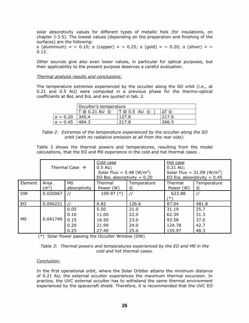
solar absorptivity values for different types of metallic foils (for insulations, on chapter J-3.5). The lowest values (depending on the preparation and finishing of the surfaces) are the following: α (aluminium) = ~ 0.10; α (copper) = ~ 0.25; α (gold) = ~ 0.20; α (silver) = ~ 0.12. Other sources give also even lower values, in particular for optical purposes, but their applicability to the present purpose deserves a careful evaluation. Thermal analysis results and conclusions: The temperature extremes experienced by the occulter along the SO orbit (i.e., at 0.21 and 0.5 AU) were computed in a previous phase for the thermo-optical coefficients at BoL and EoL and are quoted in tab. 2.
Occulter’s temperature T @ 0.21 AU © T @ 0.5 AU © ) ∆T ©
α = 0.20 345.4 127.8 217.6 α = 0.45 484.3 217.8 266.5
Table 2: Extremes of the temperature experienced by the occulter along the SO
orbit (with no radiative emission at all from the rear side). Table 3 shows the thermal powers and temperatures, resulting from the model calculations, that the EO and M0 experience in the cold and hot thermal cases .
Thermal Case
Cold case 0.5 AU; Solar Flux = 5.48 (W/m2) EO BoL absorptivity = 0.20
Hot case 0.21 AU; Solar Flux = 31.09 (W/m2) EO EoL absorptivity = 0.45
Element Area (m2)
M0 absorptivity
Thermal Power (W)
Temperature ©
Thermal Power (W)
Temperature ©
OW 0.020067 // 109.97 (*) // 623.88 (*)
//
EO 0.006221 // 6.82 126.6 87.04 481.8 0.05 5.50 21.0 31.19 25.7 0.10 11.00 22.0 62.39 31.3 0.15 16.50 23.0 93.58 37.0 0.20 21.99 24.0 124.78 42.7
M0
0.041749
0.25 27.49 25.0 155.97 48.3 (*) Solar Power passing the Occulter Window (OW)
Table 3: Thermal powers and temperatures experienced by the EO and M0 in the
cold and hot thermal cases. Conclusion: In the first operational orbit, where the Solar Orbiter attains the minimum distance of 0.21 AU, the external occulter experiences the maximum thermal excursion. In practice, the UVC external occulter has to withstand the same thermal environment experienced by the spacecraft shield. Therefore, it is recommended that the UVC EO
26

be designed following the same guidelines used for the spacecraft thermal shield and, possibly, the same material. It is also suggested that we consider using part of the spacecraft shield itself as an external occulter for the UVC. The sun-disk rejection mirror, M0, should not pose a thermal problem as long as its absorptivity remains less than 0.1 – 0.15. Therefore care must be taken in minimizing M0 reflectivity degradation due to thermal load, contamination and particle implantation. M0 deformation due to thermal loads is not critical, in that the mirror imaging properties are not stringent. M0 needs just to focus the reflected sun-disk light well enough to clear the Occulter Window. It is noted that some spacecraft-level input is required from ESTEC regarding the design of the spacecraft thermal shield. [Note added by editors: The 'cold' case used for the UVC analysis was 0.5 AU rather than 0.8 AU, the aphelion, though this will not alter the basic conclusions of the report.] References: 1. Marsch and Study Team Members, 2000, “Solar Orbiter: A High-Resolution Mission to the Sun and Inner Heliosphere,” ESA Assessment Study Report. http://solarsystem.estec.esa.nl/solar_physics/projects/solar_orbiter.htm 2. Antonucci, E., Fineschi, S., et al., 2000, Ultraviolet and Visibile-light Coronagraph for the Solar Orbiter Mission,” Proc. SPIE 4139, pp. 378 – 389. 3. Fineschi et al., 2001, “Extended UV Corona Imaging from the Solar Orbiter: the Ultraviolet and Visible-light Coronagraph (UVC),” Proc. ESA SP-492, pp. 217 – 222. Action ID Number: 1.1 - VIM & 1.2 - VIM Responsible Working Group Member: Michael Sigwarth & Achim
Gandorfer Action: Thermal feasibility study for the VIM HRT instrument This report discusses the general thermal feasibility of a VIM High Resolution Telescope (HRT) with a free aperture of 25 cm. The conclusions are based on the outcome of three industrial studies [refs 1 to 3], contracted to investigate various thermal aspects. We finally present a possible strawman design for VIM, based on the outcome of the studies. The VIM HRT was initially proposed as an open, on axis Gregorian type telescope with a free aperture of 25 cm in diameter. To keep the optics aligned, a wave-front sensor in combination with an active positioning mechanism for M2 was suggested to guarantee the optical performance. It was proposed to make the reflective optics of lightweight Cesic© [4, 5]. The overall mass limit was 13 kg for the HRT. Industrial studies have been initiated to investigate the feasibility of the initially proposed VIM HRT and to study an alternative approach using a narrow pass-band entrance filter. The studies show, that an entrance filter for VIM is feasible [2, 3]. The results are summarized in the report to action 2.6 (VIM), below. The study of the overall thermal feasibility was performed in the frame of a consulting contract with Astrium GmbH, Friedrichshafen, led and managed by Dr. N. Pailer [1].
27

Since the aim was to investigate feasibility and not to come up with a detailed thermal design, a simple thermal model was implemented that only considers radiation. Neglecting thermal conduction represents a conservative approach since conduction will help to equalize temperature gradients. The thermal load was investigated for the worst case scenario at 0.21 AU (31088 W/m²). Thermal model for VIM HRT: The feasibility assessment focuses on two designs: 1.) an open Gregorian telescope like that initially proposed (referred to as the “open design”) with a reflective heat stop at prime focus and 2.) a Gregorian telescope with a narrow pass-band entrance filter (referred to as the “closed design”) with and without heat stop. For both concepts a partially “open box” was assumed, so that the optics and telescope structure can radiate sidewise into deep space. The temperature behind the heat shield and at the interface to the spacecraft was set to 40°C. Figure 1 illustrates the thermal model.
M2
For the assessment an all-ceramic conceptunderlying with the reflective optics includstructure and mounts made of Si-ceramicsCesic© compared with other materials. The reflectivity of the mirror coatings was (case B). It is further assumed that M2 is sh The entrance filter is made of fused silica winner side of the filter. The pass-band is cencase) total transmittance of 5 %. The absor10 % of the incoming flux. Therefore 85entrance filter. The independent filter studare on the conservative side.
Table 1: The principal
Un
CTE @ RT α 10-6
28
Entrance Window
Heat rejection mirrorTelescope
M1
Figure 1: Illustration of simple thermal model of VIM HRT [1].
for the optics and telescope structure is ing heat stop made of Cesic© and the . Table 1 shows the main properties of
assumed to be 90 % (case A) or 75 % ielded from direct sunlight.
ith a dielectric multilayer coating on the tered at 630 nm with an assumed (worst ption within the filter was assumed to be % of the radiation is reflected by the ies [2] [3] show that these assumptions
properties of Cesic©
its Cesic©
CVD-SiC Zerodur
Al
K- 2.6 2.2 0.05 23

1 Thermal conductivity K W/m K 135 300 1.64 171
Specific weight ρ g cm-3 2.65 3.21 2.53 2.71
Youngs modulus E Gpa 235 466 91 69 Specific stiffness E/ρ 87 145 36 25
Steady state thermostability
EK/α 10 3
12 64 3 0.5
Dynamic thermostability
EK/αCp 18 106 4 0.05
* Values from Astrium GmbH and Rohm & Haas Company
Results from thermal model: Table 2 gives the absorption from the incoming radiation for each element for the two principal designs and shows the temperatures that result from the thermal analysis.
Table 2: Total input: 1354 W
Open Closed
A (90% reflectivity)
B (75% reflectivity)
A B
Entrance Filter* - - - - 135 W 231° C
135 W
231° C
M1 135 W
142° C
339 W
240°C 7 W -9° C 17 W 14° C
Heat Stop** 61 W
723° C
51 W 673°C 3 W 230° C 3 W 230° C
M2 2 W 22° C 5 W 55° C 0 W 99° C 0 W 99° C * Absorption of entrance filter 10% for both cases **Reflectance of heat stop 93% for both cases. Discussion: The suggested and preferred approach of Astrium GmbH was to regulate distortion by controlled heating of structural elements instead of controlled cooling and thermalisation of the whole instrument or of parts of it. This was driving the assessment towards a design that can avoid regulated heat pipes and radiators. Discussion of open concept: Temperatures for the heat stop and M1 (case B) are above 200° C which was assumed to be the upper limit. Although Cesic© mirrors can be operated in a broad temperature range from a few Kelvin up to 1500 K [5] hot optics raise the question of possible coatings with high and stable reflectivity. To keep the heat stop mirror at 200° C the required additional radiator size would be about 0.015 m² with a total mass (including heat pipes) of about 0.6 kg. A high and long term stable reflectivity of the heat stop mirror is mandatory. Cooling of M1 by radiator would require another 0.9 kg of thermal hardware.
29

Discussion of closed concept: It is obvious that the thermal situation for the closed concept is much more relaxed. The use of an entrance filter would even allow us to abandon the heat stop. Without a heat stop M2 will heat up to 143° C (case A) or 181° C (case B). The reason for the higher temperature of M2 compared to the open design is the heating by infra red radiation from the entrance window. On the other hand the entrance filter protects M2 automatically from direct sunlight while for the open design the shielding of M2 from direct sunlight (e.g. from the heat shield) is necessary. The additional mass of about 2 kg for the entrance filter (including support structure) can partially compensated by avoiding the heat stop and reducing thermal hardware. Beside the advantage for the thermal concept, the entrance filter would also protect the M 1 coating from UV and particle radiation. An entrance door is not mandatory for a closed telescope. Discussion of closed box: Astrium performed a basic thermal assessment for a VIM HRT with a reflective entrance window and no heat stop in a closed box. The assumption was that the temperature of the telescope box should not exceed 40° C under a worst case scenario. In order to reach that goal a deep space oriented radiator of 0.4 m² (approx. 4.5 kg) would be required. The resulting temperatures of the optical components are listed in Table 3 for high and low reflectivity of M1 and M2. Table 3:
Total input: 1354 W
M1 M2 Heat Stop
Entrance Window
Case A (90% reflect.)
65°C
161°C
- 245°C
Case B (75% reflect.)
80°C
198°C
- 247°C
Thermal regulation and optical performance: The Astrium assessment demonstrates that for a partially open box a VIM HRT with entrance window can operate at reasonable temperatures without need for additional radiator. Because of the non isotropic heat dissipation, temperature gradients within the structure and optical components will occur. The good thermal conductivity of Cesic© and Si-ceramics will help to relax the gradients compared to the worst case situation of the simple thermal model. Heating of the telescope structure allow to compensate for distortion within the support structure. The entrance window should be thermally insulated to the support ring and will radiate mainly along LOS. Temperature gradients within M1 are most critical and need to be quantified in a detailed analysis. A possible solution could be a local thermally closed box (“shade”) around M1. The all-ceramics concept provides a homogeneous behavior of the whole telescope at different temperatures (athermal design). Fine adjustment of the M1/M2 alignment is possible due to active heating of the support structure. The tolerances for lateral decenter of M1/M2 (relative to the optical axis) are not critical and are not affected by temperature changes due to the athermal design. Decenter along the optical axis as well as tilt can be controlled by active heating in combination with a focus
30
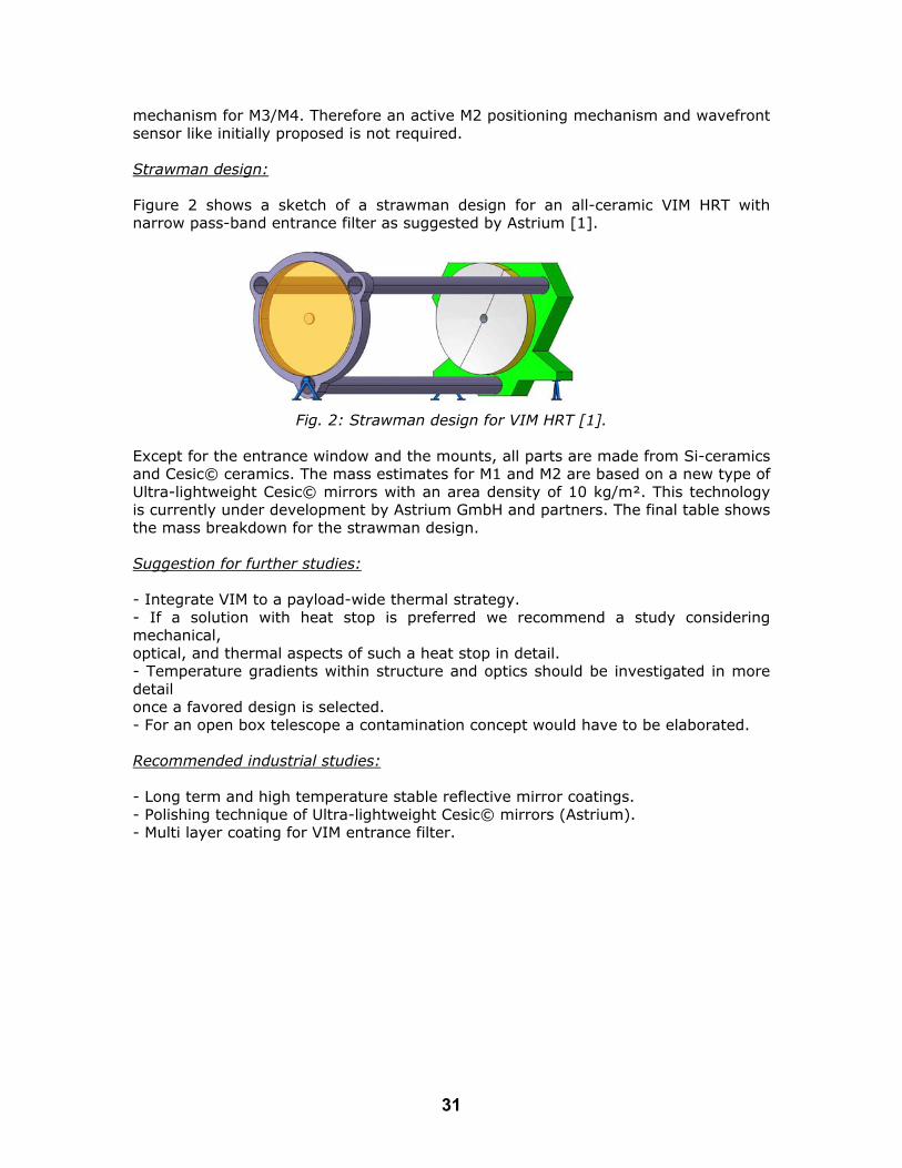
mechanism for M3/M4. Therefore an active M2 positioning mechanism and wavefront sensor like initially proposed is not required. Strawman design: Figure 2 shows a sketch of a strawman design for an all-ceramic VIM HRT with narrow pass-band entrance filter as suggested by Astrium [1].
Fig. 2: Strawman design for VIM HRT [1].
Except for the entrance window and the mounts, all parts are made from Si-ceramics and Cesic© ceramics. The mass estimates for M1 and M2 are based on a new type of Ultra-lightweight Cesic© mirrors with an area density of 10 kg/m². This technology is currently under development by Astrium GmbH and partners. The final table shows the mass breakdown for the strawman design. Suggestion for further studies: - Integrate VIM to a payload-wide thermal strategy. - If a solution with heat stop is preferred we recommend a study considering mechanical, optical, and thermal aspects of such a heat stop in detail. - Temperature gradients within structure and optics should be investigated in more detail once a favored design is selected. - For an open box telescope a contamination concept would have to be elaborated. Recommended industrial studies: - Long term and high temperature stable reflective mirror coatings. - Polishing technique of Ultra-lightweight Cesic© mirrors (Astrium). - Multi layer coating for VIM entrance filter.
31

* Different geometry necessary; first mass value valid for I/F to S/C at bottom of telescope, second mass value for I/F to S/C on side. Values from [1]
Part No. Material MASS DENSITY
MASS Margin
Total Mass
[g/cm³] [kg] [kg] Entrance Window 1 fused
silica 2,2 1,17 25% 1,46
M1 1 Cesic 2,6 0,50 25% 0,63 M2 1 Cesic 2,6 0,05 25% 0,06 Kinematic Mount (ISM) 3 Titan 4,5 0,016 25% 0,02 Mount for M1 3 Titan 4,5 0,016 25% 0,02 Primary Straylight Baffle
1 0,15
Baseplate 1 Si-
Ceramics 2,6 3,89 /
4,33* 25% 4,86 / 5,41
*
Tube 3 Si-
Ceramics 2,6 0,44 25% 1,65
Support Ring Entrance Window
1 Si-Ceramics
2,6 0,50 25% 0,63
Additional parts Prefilter at primary hole 1 0,40 Structure Heater Control
1 0,30
Structure MLI 1 0,30
Conclusion: A VIM HRT with 25cm aperture is feasible within the mass limits given. For both concepts (open and closed) we could not identify real show stoppers. For an open telescope a heat stop is necessary. It has to be identified as a critical
item. A closed telescope with reflective entrance window could work even without a
heat stop. In any case the requirements for a heat stop and the general thermal concept would be more relaxed compared to the open case.
From a thermal point of view a closed telescope with an entrance filter or even a lens is the preferred solution.
With the proposed all-ceramics concept we are confident that a wavefront sensor and M2 positioning mechanism is not necessary.
[Note added by editors: An additional important consideration is the temperature variation, over the orbit, which has not been included to date.] References: [1] VIM Telescope Consulting Assessment, Astrium GmbH, 2003 [2] Machbarkeitsstudie Sonnenfilter. Mso Jena. Jena 2003 [3] Thermalanalyse eines Sonnenfilters für VIM, Kayser-Threde, München, 2003 [4] Lightweight Cesic© Mirrors and their Applications, Pailer et al., in: “Innovative Telescopes and Instruments for Solar Physics”, SPIE, 2002, in press
32
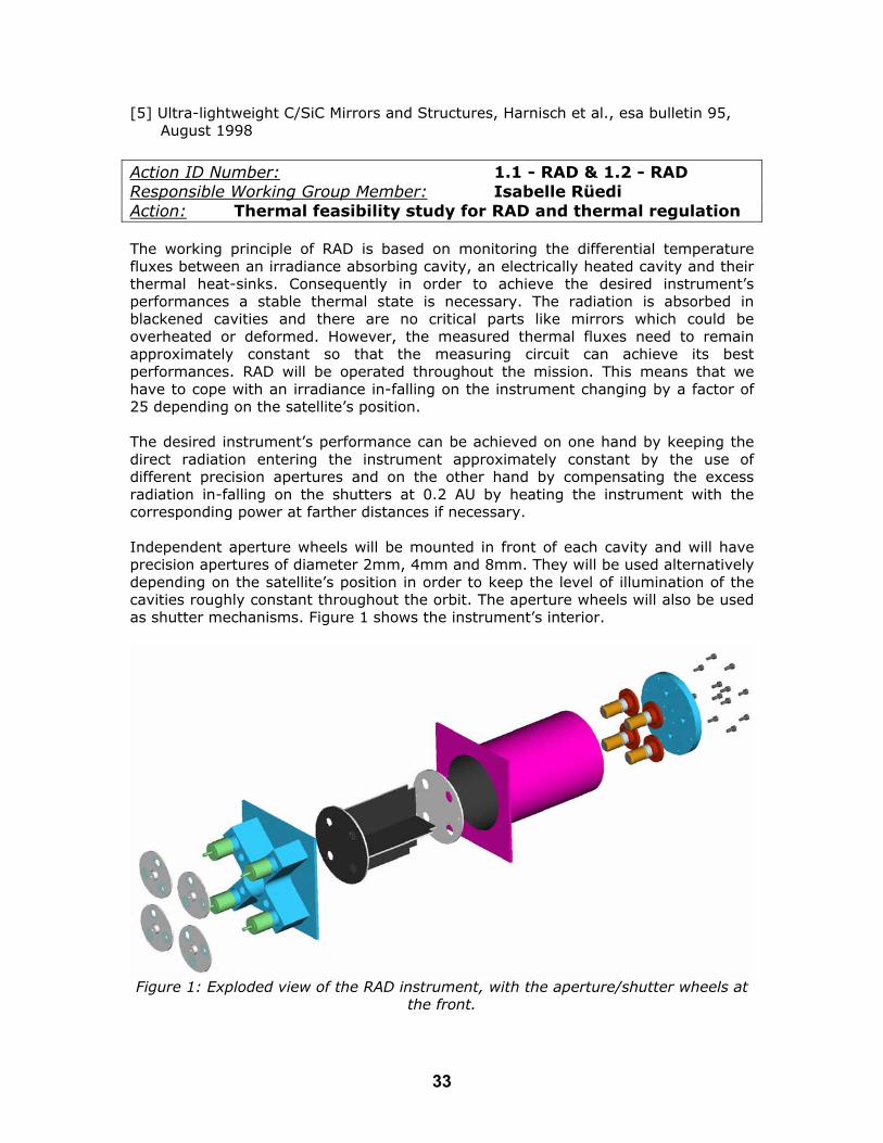
[5] Ultra-lightweight C/SiC Mirrors and Structures, Harnisch et al., esa bulletin 95, August 1998 Action ID Number: 1.1 - RAD & 1.2 - RAD Responsible Working Group Member: Isabelle Rüedi Action: Thermal feasibility study for RAD and thermal regulation The working principle of RAD is based on monitoring the differential temperature fluxes between an irradiance absorbing cavity, an electrically heated cavity and their thermal heat-sinks. Consequently in order to achieve the desired instrument’s performances a stable thermal state is necessary. The radiation is absorbed in blackened cavities and there are no critical parts like mirrors which could be overheated or deformed. However, the measured thermal fluxes need to remain approximately constant so that the measuring circuit can achieve its best performances. RAD will be operated throughout the mission. This means that we have to cope with an irradiance in-falling on the instrument changing by a factor of 25 depending on the satellite’s position. The desired instrument’s performance can be achieved on one hand by keeping the direct radiation entering the instrument approximately constant by the use of different precision apertures and on the other hand by compensating the excess radiation in-falling on the shutters at 0.2 AU by heating the instrument with the corresponding power at farther distances if necessary. Independent aperture wheels will be mounted in front of each cavity and will have precision apertures of diameter 2mm, 4mm and 8mm. They will be used alternatively depending on the satellite’s position in order to keep the level of illumination of the cavities roughly constant throughout the orbit. The aperture wheels will also be used as shutter mechanisms. Figure 1 shows the instrument’s interior.
Figure 1: Exploded view of the RAD instrument, with the aperture/shutter wheels at
the front.
33

The precision apertures are placed in the aperture wheel at the front of the instrument while the view limiting apertures are located at the back, just in front of the cavity. This arrangement has the advantage to reduce stray-light in the instrument which is a crucial parameter due to the large irradiance changes expected across the orbit. To show the thermal feasibility of the RAD experiment we take as a starting point our experience with the VIRGO experiment on SOHO which contains radiometers working on the same principle and which is performing well. There, a thermally controlled sun-shield and base plate are provided by the satellite. In this report we consequently only address the aspects, which are specific to the Solar Orbiter mission due to the changing irradiance along the orbit. For this estimation we assume that a front radiation shield of constant temperature is provided by the spacecraft. Four holes have to be provided in this shield to let the radiation enter the instrument. These holes will have a diameter of 12 mm. The aperture wheels which at the same time work as shutter mechanisms will be covered with back surface mirrors. At 0.2 AU the radiation falling on the instrument shutters/apertures will be larger than at 1.2 AU. This excess radiation has ideally to be compensated at larger distances from the Sun in order to keep a constant instrument’s temperature. The worst case will occur at the end of the mission, when the reflectivity of the back-surface mirrors will have degraded (EOL absorption coefficient of 0.15). This excess radiation corresponds to: P= 4 * 0.15 * π*(6*10-3)2 *1370 ((1/0.21)2 - (1/1.21)2)= 2.04 W Conclusion: This report shows that the irradiance changes throughout the orbit do not pose a major problem for continuous operation of the RAD instrument as far as the thermal control of the instrument is concerned. However, it should be noted that this assumes a stable thermal environment of the surroundings of the RAD instrument provided by the satellite. If other instruments’ or spacecraft’s parts which are surrounding RAD experience very strong temperature excursions, RAD’s performances might be altered. It was assumed that a front sun-shield of constant temperature and a base temperature control is provided by the satellite! Action ID Number: 1.1 - STIX & 1.2 - STIX Responsible Working Group Member: Bob Lin & Gordon Hurford Action: Thermal feasibility for the STIX instrument The thermal shielding issue for STIX is readily address by an opaque sunshade. The entrance aperture of STIX can be covered by a sunshade in the form of C-C in front of multilayer Beryllium. This is not a problem for STIX imaging because it requires shielding in any case to suppress the intense flare flux of low energy solar x-rays. Although not thermally significant, this low energy x-ray flux would otherwise overwhelm the detectors’ ability to handle individual photons. For a 3 keV observing threshold, the optimum sunshade thickness for x-rays is equivalent to ~1 mm of
34
Carbon or 3 mm of Beryllium. With a suitable design, such a sunshade should provide suitable thermal protection as well. The sunshade would require 2 open apertures (each ~0.1 x 50 mm) in front of the aspect elements. At 0.2 AU such apertures would transmit about 340 mW. About 50 mW of this would be transmitted to the lower grid tray inside the instrument while the remainder would be absorbed or reflected by the top tungsten grid. If necessary a thin reflective coating could be applied to the grids without affecting their imaging performance. One unresolved issue is whether the sunshade should be provided by the spacecraft or by the instrument. An additional design issue is the tradeoff between co-alignment accuracy of the sunshade apertures (that determines their width and transmitted heat load) and the feasible level of heat dissipation/reflection by the front grid. Action ID Number: 1.1 - HI & 1.2 - HI Responsible Working Group Member: Clarence Korendyke Action: Thermal feasibility for the HI instrument The HI telescope or telescopes (depending on whether one or two units is carried), view deep space with a field of view shielded from the Sun. There is no direct solar illumination on any surfaces internal to the HI instrument. Thus, the thermal design relies on standard methods (radiator, heaters, thermal blanket) with a nominal heater power required of about 3 Watt per unit. The thermal concept is similar to that of the Heliospheric Imager on the NASA STEREO spacecraft. The instrument would be located on the side of the spacecraft, and would lie at least partly in the shade of the Solar Orbiter front shield, which extends beyond the edge of the payload module. However, the vanes, which define the (sharp) edge of the field of view of the instrument would see direct sunlight and would need to be thermally shielded from the internal components of the instrument. Since no direct sunlight enters the optical system, the thermal control of HI is regarded as conventional and feasible. Action ID Number: 1.3 - EUS Responsible Working Group Member: Richard Harrison Action: To demonstrate that the restricted telemetry rate is sufficient to achieve the scientific goals of EUS. The nominal telemetry rate for the EUS instrument is 17 kbit/s. The full EUS detector image is 4kx4k pixels. At 12 bits per pixel, it will take 197 min to read one exposure. Since each exposure will form part of a raster, the raster cadence will be significantly longer. Studies from instruments such as CDS/SOHO (ref. 1) have shown that careful line selection is far more important than data compression in managing the data return. Much of the spectrum is not required. Indeed, for specific studies, specific emission lines are required. A good rule of thumb from SOHO is that a selection of between 6 and 15 lines is good for most scientific purposes. The EUS nominal resolving element is 0.5 arcsec along a 34 arcmin slit (4k pixels). The nominal spectral resolution is of order 0.01 Å/pixel. To obtain full line widths for
35

million K lines, plus sufficient nearby background, one would want to return about 0.3 Å, i.e. 30 pixels. The table shows a selection of potential cases. In each case a number of required lines is defined as is a length along the slit (spatial direction). The time to return such an exposure is given with a stated compression factor. The rastered image cadence is then given for four cases. The spatial length is given in pixels because of the varying distance to the Sun. We assume a return of 30 pixels across each line and 12 bit words. No. of lines
Spatial Length
Compression Factor
Time to return exposure
Cadences for 200 (100 arcsec), 500 (250 arcsec), 1000 (500 arcsec) and 2000 (1000 arcsec) steps (minutes)
10 100 10 2.1 sec 7 18 35 70 6 500 3 21.2 sec 71 177 353 707 6 500 10 6.35 sec 21 53 106 212 10 500 10 10.6 sec 35 88 177 353 6 1000 3 42.4 sec 141 353 707 1413 6 1000 10 12.7 sec 42 106 212 423 10 1000 10 21.2 sec 71 177 353 707 6 2000 3 84.7 sec 282 706 1411 2823 6 2000 10 25.4 sec 85 212 423 847 6 4000 10 50.8 sec 170 414 846 1694 This table shows that the telemetry rate is very limiting for the majority of rastered images. Given the dynamic/transient nature of the Sun’s atmosphere, we should be looking for cadences of order minutes. For some, specific solar applications, the figures of the above table are fine. This would include Small area (under 50x50 arcsec) rasters to investigate fine-structure dynamic
events (e.g. 3.5 min raster with 10 lines in 50x50 arcsec FOV); Single-slit location sequences (i.e. no raster – the slit stays at one place
monitoring intensities with one spatial dimension) to study transient intensity events such as blinkers and explosive events (e.g. 10.6 sec resolution observation over 250 arcsec with 10 lines). Spectral atlas studies, which are seeking evidence for line identifications and
discoveries using long-duration runs. However, for many studies, we need to find methods for improving the performance to avoid compromising the scientific return. Several options are possible: 1. Increase the telemetry rate: This option should be sought from the Project in any
case; 2. Return line profile parameters rather than the full profile information; 3. Return image differences rather than full images. These are just three options, one of which is beyond the control of the EUS study team! Returning the line profile parameters would reduce the data return by a factor of up to 0.1 (at best, 3 parameters instead of the 30 bins). Alternatively, we may wish to return 15 bins (2:1 summing) across the line rather than the full 30, if we
36

are wary of the profile parameter method. The savings are illustrated below for the 1000 pixel length studies of the table above. No. of lines
Spatial Length
Compression Factor
Time to return exposure
Cadences for 200 (100 arcsec), 500 (250 arcsec), 1000 (500 arcsec) and 2000 (1000 arcsec) steps (minutes)
1. Basic Method 6 1000 3 42.4 sec 141 353 707 1413 6 1000 10 12.7 sec 42 106 212 423 10 1000 10 21.2 sec 71 177 353 707 2. 2:1 Line Profile Summing Method 6 1000 3 21.2 sec 70 177 353 707 6 1000 10 6.3 sec 21 53 106 212 10 1000 10 10.6 sec 36 89 177 353 3. Line Parameter Method 6 1000 3 4.2 sec 14 35 71 141 6 1000 10 1.3 sec 4 11 21 42 10 1000 10 2.1 sec 7 18 35 71 In addition to this, the feasibility of the image differencing method should be examined by any proposing EUS team. However, the figures in the second table do now show cadences of order under 10 minutes and this is encouraging. This report has assumed the nominal telemetry rate of 17 kbit/s. This figure is based on the 240 Gbit onboard memory for the payload and the single ground-station data dump scenario. In anticipation of improvements in ground-station coverage and on-board memory capacity, we briefly examine improvements in the telemetry rate of factors of 3 and 10, i.e. 51 kbit/s and 170 kbit/s. No. of lines
Spatial Length
Compression Factor
Time to return exposure
Cadences for 200 (100 arcsec), 500 (250 arcsec), 1000 (500 arcsec) and 2000 (1000 arcsec) steps (minutes)
Telemetry Rate of 51 kbit/s: 6 4000 10 16.9 sec 56 140 280 560 6 2000 10 8.45 sec 28 70 140 280 6 1000 10 4.23 sec 14 35 70 140 Telemetry Rate of 170 kbit/s: 6 4000 10 5.08 sec 17 70 140 280 6 2000 10 2.54 sec 8 35 70 140 6 1000 10 1.27 sec 4 17 35 70 Telemetry Rate of 51 kbit/s with Line Parameter Compresion Method: 6 4000 10 1.6 sec 5.2 16 28 56 6 2000 10 0.8 sec 2.6 8 14 28 6 1000 10 0.4 sec 1.3 4 7 14 It is clear that there are very significant improvements in the performance with increased telemetry rates, providing reasonable rastered observations with cadences of under 10 minutes. Conclusion:
37

The figures demonstrate that the operation of an EUS instrument is feasible with the 17 kbit/s telemetry allocation given careful data selection and compression. The basic scientific goals of the instrument are not compromised but it is very restricting. It is clear that a greater telemetry allocation is highly desirable and would provide a MUCH improved scientific return. The nominal telemetry allocation is extremely low and we would suggest that the following actions be considered by the Solar Orbiter Project and by any proposing EUS team to improve significantly the scientific return: - The Project to consider possibilities for increasing the EUS telemetry rate
allocation from 17 kbit/s; factors of 3 or 10 show significantly better scientific return, and it is felt that with increased onboard memory and improved ground coverage, this will be feasible. This must be taken as an urgent action.
- In addition, proposing EUS teams should study methods for novel data selection and compression, such as returning image differences rather than raw images, and line profile parameters, to aid certain scientific study requirements.
References: 1. Harrison et al., 1995, Solar Phys. 162, 233. It is recommended that the Project study possibilities for increasing the instrument telemetry rate (not just EUS) allocation; factors of 3 and 10 show significantly better scientific return. With increased on board memory (above that given in the July 2000 proposal) and more than one ground station (one was baselined in the original study), this should be feasible.
Action ID Number: 1.3 - EUI Responsible Working Group Member: Jean-François Hochedez &
Don Hassler Action: To demonstrate that the restricted telemetry rate is sufficient to achieve the scientific goals of EUI. The EUI in the July 2000 Study Report consists of three high-resolution imaging telescopes (HRI) and one full-Sun imaging telescope (FSI). They all use 2kx2k imaging detectors, but the HRI cadence is anticipated to be 10 s when the FSI would only work at a 4800 s cadence. These values amount to a production of 14410 kbps assuming only 12 bits per pixel and no compression. The allocated averaged telemetry rate was 20 kbps. It is a factor 720.5 below that needed, as it is formulated in the Study Report. There, the discrepancy is solved by the combined usage of lossy algorithms (a gain 50 is mentioned), binning (another way to compress with loss), and observing strategies (varying resolution, wavelength selection, interleave modes). The concern can be made even more apparent if higher - yet legitimate - requirements are introduced: the signal dynamics could be expected to be 14 bit instead of 12, and more serious, the required cadence can be demonstrated to be 10 Hz for the HRIs in order to be homogeneous with their 35 km pixel at the Sun. Additionally, the Solar Orbiter detector standard format has been raised to 4kx4k. This leads to very large peak telemetry rates of the order of 6720 Mbps for the 3 HRIs, a factor 336000 above the average availability.
38

Such a huge discrepancy will neither be solved by the best compression schemes, nor by the highest realistic increase of telemetry bandpasses, even though they both should be maximised because all other solutions will be, to some extent, at the expense of the Science return of the mission. The best lossless compression schemes are of the order 3-10, and the telemetry could be hoped to improve by also 3. Slightly lossy (almost lossless) compression schemes, such as those developed for the Solar Probe mission (Hassler et al. 2000), involve wavelet compression algorithms, which operate on large portions of the image at once, allowing higher compression ratios than Fourier techniques such as JPEG. Tests of wavelet compression using solar data show that such algorithms can preserve both photometry and small-scale morphology even at very high compression factors. Sample tests have shown that reconstructed images using wavelet compression differ by the original image by less than 10 DN everywhere and less than 1 DN in all but 0.06% of the pixels, even with compression ratios as high as 48:1. Thus, with the most stringent format and dynamic range requirements discussed above, we are left a data production rate 2,240x greater than can be handled by the telemetry and compression technique improvements. This remaining discrepancy must then be handled by imaging format (design spec), binning (in-flight), and observational strategy (that is, duty cycle). We propose that the format of the HRI detectors be anticipated to be less ambitious than 4kx4k, and be rather expected to be in the 1kx1k range. This would avoid useless optical design efforts that would rarely be benefited of. The FOV should not suffer too much however, and the pixel at the Sun could be brought to ~50 km, which would already be awesome. The cadence requirement would then be slightly relaxed (by ~1.4), and the instrument specifications, physically homogeneous. The “excess” of data is down to ~140 in this way. Rather than implementing lossy compression to these precious data, we suggest to carefully emphasize a priori and a posteriori data selection. Almost-lossless schemes (with well restricted loss) should still be studied and implemented in the onboard software, possibly at later mission stages, when the very nature of the data (contrast, fill factor, etc.) has been observed and acknowledged. 1. A posteriori data selection consists of on-board image processing routines able to robustly qualify the content of the image sequences. Solar Orbiter is a non-synoptic mission, in that sense it rather need the most interesting sequences (which will sometimes be mere QS) rather than regular sampling, already restricted by the tiny HRI FOV. In other words, the scientific relevance of the data is key. The criteria will obviously include the occurrence of joint programs with the other instruments of the payloads or with other missions or telescopes, the integrity of sequences, etc. They could furthermore implement preferences for features not yet observed. They can be based on simple/robust schemes such as the distributions of scale and brightness (histograms). This filtering could provide a factor ~20 in the TM reduction quest, bringing the excess factor down to 7. Such information could be shared among the whole payload leading to the autonomous decision to drop altogether, or not, a given “JOP”, providing hence auto-leverage. This would be done with respect to the knowledge of the mission mass memory occupation. A side effect of such a filtering would be that the instruments would operate 20x more than they effectively
39

downlink. This 5% duty cycle, depending on the onboard CPU power, will put additional robustness requirements on the optics, and particularly on the detectors. 2. A priori data selection means target selection. This capability is already implicit in the basic fact that the spacecraft will often be out of contact, especially when it is on the other side of the Sun. Pointing automatically a detected BP or CH boundary is not fundamentally different than pointing the Sun Centre or the predicted location of an AR. Other considerations will be taken into account such as orbital parameters (distance to the Sun, ecliptic latitude) in the choice of the target. With the above hypothesis, and assuming that only a third of the orbit is worth HRI observations (perihelion and phases outside the ecliptic), HRI will observe 24*3/140*20 ~ 10.3 hours ~ 620 min per day of interest (207 min per day on average) based on the processing of FSI and in situ observations, and downlink the most useful 30 minutes… An increase up to a few hours can be hoped for with the help of augmented TM during certain orbits (p.67 of the S.O. ASR). The usage of the above daily resource shall be optimized over longer timescales (weeks to month), particularly in view of co-rotations. The operational duty-cycle (207min/24h=14%) will have to be tuned to account not only for the DPU power but also for the electrical power availability. Given the outstanding contextual and EP/O interest of the FSI, it is recommended to keep its TM allocation above 10% of the HRI, ie. 2kbps. Within a 2k^2 format, 12 bit, :3 lossless compression, x3 TM mission increase, 2kbps lead to an acceptable 45min cadence all around the orbit. Variable binning/windowing could be used to match the cadence with the resolution changes resulting from the orbit eccentricity. Conclusion: The telemetry budget is a clear bottleneck for the EUI. Any progress of its overall telemetry allocation will provide direct enhancements to its scientific return. The same stands for gains in the lossless compression schemes and to lossy algorithm if their impact on the science analysis is perfectly controlled. To cope with the lack of bandpass, EUI and most Solar Orbiter instruments will have to implement a severe onboard filtering of the observations both before pointing and after acquisition in memory. This should occur on the most scientifically relevant, and technically robust basis. References: ESA-SCI(2000)6 Solar Orbiter Assessment Study Report, July 2000, ESA. Action ID Number: 1.3 - UVC Responsible Working Group Member: Silvano Fineschi Action: UVC Telemetry Requirements This report is intended to demonstrate that the restricted telemetry rate available to the Solar Orbiter payload is sufficient to achieve the scientific goals of the Ultraviolet and Visible-light Coronagraph (UVC). The strawman UVC instrument is comprised of two 4k × 4k detectors: one for the UV/Extreme-UV and the other for the visible-light (VL).
40

Assuming a 2 × 2 pixel binning, corresponding to a spatial resolution ≈ (30 arcsec)2, a 2k × 2k image with 2 Bytes (B) per bin takes ≈ 8 MB. Only 70% of the image is used (the rest is occulted disk), thus an uncompressed image is ≈ 6 MB. The expected countrates of the UV/EUV channels are shown in Fig. 1 (Fineschi, et al., 2001). Based on these countrates, and considering acceptable a SNR ≈ 10 for the outer boundary of the field-of-view (FOV), then about 103 s (≈ 15 min) are needed for HI and HeII Lyman-α images of the corona up to the outer FOV boundary, including coronal holes. Assuming
1. 100 images/day/detector, and 2. that the VL detector works in parallel with the HI Lyman-α channel 60% of
the time, then a full day of observations takes 150 images. This corresponds to ≈ 1.2 GB of uncompressed data. This requires 14 kB/s peak, or half of that with lossless compression, that is, 7 kB/s = 56 kbit/s.
Figure 1 Left panels: Coronal HeII 30.4 nm and HI 121.6 nm radiances from equatorial (solid line) and polar (dash line) regions. Right panels: Expected countrates for the UVC’s HeII 30.4 nm and HI 121.6 nm paths. (Fineschi, et al. 2001.)
41

During the nominal observation mode, with Solar Orbiter’s expected telemetry rate at 75 kbit/s, lossy compression schemes with compression factors from 5 to up to 10 will have to be used. In this case, the UVC telemetry rate requirement would be in the range comprised between 10 to 20 kbit/s. Conclusion: The limited Solar Orbiter’s telemetry rate (≈ 75 kbit/s) is sufficient to accommodate the 10 to 20 kbit/s telemetry range necessary to UVC to achieve its scientific objectives. However, the telemetry allocation is extremely low and it is suggested that the following actions be considered by the Solar Orbiter Project to improve significantly the scientific return: - The Project to consider possibilities for increasing the Solar Orbiter telemetry rate
allocation; - The Project to consider possibilities for allowing UVC to observe also outside of
the 30-day nominal mode period at perihelion. That is, when observations at a lower rate (11.5 kbit/s) will take place. Also, for spacecraft/Sun distances larger than 0.5 AU.
The last point is worth being considered in view of the fact that a coronagraph on a platform such as the Solar Orbiter would still be able to carry out valuable scientific observations of the extended solar corona, and of the interplanetary medium, even when the spacecraft is not at perihelion. References: Fineschi, S., Antonucci, E., Gardiol, D., Da Deppo, V., Naletto, G., Romoli, M., Cacciani., A., Malvezzi, M., 2001, “Extended UV Corona Imaging from the Solar Orbiter: The Ultraviolet and Visible-light Coronagraph,” ESA SP-493, pp. 217-222. Action ID Number: 1.3 - VIM Responsible Working Group Member: Valentín Martínez Pillet Action: Demonstrate that the limited telemetry can be used to provide the science return expected from the Visible-light Imaging Magnetograph. The nominal detector for VIM is a 2K x 2K pixel, 12 bits system that can receive light from either a high resolution or a low resolution channel, each one providing different spatial samplings and field of views (FOV). For this action item, both channels are treated the same and the use of one or the other will depend on the science operation mode of the spacecraft. VIM will detect intensity images in different positions within a selected spectral line and in different polarization modes (probably including an unpolarized mode). For calibration purposes, sometimes, these intensity frames (or the Stokes parameters
42

easily deduced from them) will be stored. But these data will represent a small fraction of the total and will not compromise the telemetry rates. Here we consider only the cadences and telemetry rates needed for different observing modes that should constitute the fundamental science operation modes of the instrument. The use of these modes will depend on the science targets selected for each orbit based on the science plans of the spacecraft. In any of these modes, VIM will provide a combination of the following physical magnitudes: - Ic or continuum intensity images. A temperature indicator that provides the
photospheric context. 8 bits compressed to 4 bits per pixel. - Vlos the line-of-sight (LOS) velocity frames. They provide the Doppler signals
needed for local helioseismology. 10 bits compressed to 5, some applications may use only 4.
- Blos the LOS component of the magnetic field. They are basically maps of circular
polarization over the observed area. 10 bits compressed to 5, some applications may use only 4.
- Btrans the transverse to the LOS component of the magnetic field. They represent
maps of linear polarization. 8 bits compressed to 4. - φ the azimuth of the transverse component in a plane perpendicular to the LOS.
Also obtained from linear polarization measurements. 8 bits compressed to 4. The final 4/5 bits per pixels estimates provided here, assume a lossless compression scheme with an efficiency of a factor 2. Note that from the original 12 bits we have first thrown out the 2 to 4 less significant ones. Thus the total reduction factors are between 2 to 3. These compressed estimates have been used in the following description of example observing modes that could produce the desired scientific results from VIM. Mode 1. Low resolution, high cadence mode: On-chip binning to 512 x 512 pixels of 1 physical magnitude at a cadence of 1 per minute require a telemetry rate of 18-22 kbs. This mode can be used for storing Vlos
over the whole FOV at a high cadence for local helioseismology. This mode uses the nominal telemetry rate of 20 kbs. Mode 2. Medium resolution, medium cadence mode: Binning to 1024 x 1024 pixels of 1 physical magnitude at a cadence of 1 every two minutes require a telemetry rate of 35-44 kbs. This mode can be used for sending Ic, Vlos or Blos for general purposes (e.g., magnetic field evolution). This mode uses a telemetry rate 2 times larger than the nominal value of 20 kbs. Mode 3. High resolution, high/medium cadence mode: This mode is similar to the two previous ones but instead of binning pixels, a selection of a subframe (512 or 1024) is done, thus prioritizing spatial resolution at the expenses of FOV and keeping a reasonable cadence.
43

This mode uses a telemetry rate up to 2 times larger than the nominal value of 20 kbs. Mode 4. Photospheric context: In this mode three quantities (Blos, Btrans and φ for vector magnetometry or Blos, Vlos, Ic for dynamical studies) can be sent over the full 2K frame every 5 minutes at a rate of 160 kbs (4 bits per magnitude). The vector magnetometry case enables to follow the evolution of the magnetic field in the photosphere and higher at a sufficiently high cadence for most of the coronal phenomena. This mode uses a telemetry rate 8 times larger than the nominal value of 20 kbs. One expects the use of mode 4 (or similar) frequently during perihelion phases. This would strongly indicate the need to investigate higher telemetry rates (at a spacecraft level) and/or the use of lossy schemes whenever these modes are used. Peak telemetry rates of 3 physical magnitudes over the full frame every minute of 800 kbs (40 times the nominal value) must also be considered. As it is evident VIM will require often larger rates than the nominal one. The way in which this could be achieved is: - By using those orbits where the telemetry rates of the spacecraft are larger than
the nominal 75 kbs, by factors between 2 to 8 (see Assessment Study) . Thus careful planning of the scientific objectives of each orbit should be made beforehand.
- By increasing the resources of the spacecraft (in realistic ways as increased on-board memory, a second downlink ground station). Nominal telemetry rates 8 times higher than the current values allow near optimum scientific return at all orbits.
- By studying lossy approaches that do not compromise the science output of some experiments. This point should be of interest to all instruments and experience from other spacecrafts under development is available. We propose to study this point in a coordinated way between all science teams in the future.
- By pre-programming flexible data acquisition rates in parallel with the rest of the instruments. Modes that demand high telemetry rates should have low duty cycles.
Conclusion: As it is shown, even with the nominal telemetry rates of 20 kbs VIM will be able to provide magnetic and velocity context data to help our understanding of the upper atmospheric processes studied by the rest of the instruments. The science goal of local helioseismology puts a high demand on observing cadence but not so strong on spatial resolution. Modes 1 and 2 have telemetry rates that can be accommodated in different orbits to achieve this science goal. The same is true for observing modes with a small field of view but high spatial resolution. However, modes with full field of view and high spatial resolution (and/or high temporal cadence) indicate a clear need for higher telemetry rates (up to a factor eight) than the current nominal values. These modes can also achieve better telemetry
44

performance through the use of lossy compression approaches (with compression factors higher than 3) but their impact on the scientific quality of the data must be investigated. References: ESA-SCI(2000)6 Solar Orbiter Assessment Study Report, July 2000, ESA. Action ID Number: 1.3 - RAD Responsible Working Group Member: Isabelle Rüedi Action: To demonstrate that the restricted telemetry rate is sufficient to achieve the scientific goals of RAD. The nominal RAD telemetry rate stated in the Solar Orbiter assessment study is 0.5 kb/s. The purpose of RAD is to determine the solar irradiance. To achieve this aim, the heater currents of 2 radiometers need to be monitored. The current will be sampled at a frequency of 100 Hz with a resolution of 16 bits. This corresponds to an average daily rate of 3.2 kb/s plus some housekeeping data (3b/s). However, this data rate will only be needed during test phases or in case of problems. In normal operation, it is planned to evaluate the radiometer measurements onboard. The data will be frequency analyzed and only the in-phase signal at the shutter frequency will be necessary for the computation of the irradiance. However, the values of some of the harmonics will also be transmitted to ground in order to characterize the temporal behavior of the detectors. Since one phase lasts 100 s, only one irradiance value needs to be computed for every 100 s for each radiometer. Assuming 20 values from the frequency analyzed data are transmitted during every 100 s phase for each radiometer, this corresponds to a reduction of 500 in comparison to the raw data and corresponds to 6.4b/s plus the 3b/s housekeeping data. And corresponds to less than 10b/s. Conclusion: In normal operation RAD is able to function with less than 10b/s telemetry rate. However, in test phases or in cases of problem, the necessary telemetry rate may raise to 3.2kb/s for short periods. Action ID Number: 1.3 - STIX Responsible Working Group Member: Bob Lin & Gordon Hurford Action: STIX Telemetry Study Expected count rates from the detector system will vary from a few counts per second during background periods to more than 106 counts/second during intense flares. The key on-board data handling challenge is to process and compress these data in order to allow ground-based image reconstruction from a modest telemetry volume. No image reconstruction is done on board.
45
Each detected photon generates an output pulse from a single CZT detector element. Such analogue pulses are shaped and amplified by front-end electronics and then digitised into one of 16 energy channels. Initial data processing consists of accumulating such events according to their energy and detector into one of 16x64 (1024) energy/detector bins. A basic instrument time resolution of 1/8 second results in an initial data rate of ~16 kBytes/second. A rotating 64-Mbyte buffer stores ~1 hour of this full-resolution data within the instrument. Within the context of this 1-hour time frame, an autonomous instrument processor is used to form detector- and time-averaged spectra and detector-and energy-averaged light curves. Enhanced count rates in the light curves are used to identify flare time intervals for imaging. The processor then calculates statistically significant sums over adjacent time bins and/or energy channels. The data for a single image is then in the form of 64 2-byte numbers, representing the counts in each detector element for the selected time/energy interval. The image morphology and location is represented by the relative values of these counts and can be expressed as a corresponding set of 64 4-bit binary fractions relative to the maximum count among the 64 values. Compressing the total counts to 8 bits, the image can then be stored as this 8-bit total plus 64x4 bits of relative counts plus 7 bytes of miscellaneous information for a total of 40 bytes per image. Assuming a long-term average of 6 minutes of flare data per hour, imaging in an average of 10 energies bands with an average 2-second cadence implies a requirement of 1800 images per hour. Adding 25% for aspect, housekeeping and non-imaging datasets results in an average data rate of 200 bits/second. The science output of the STIX instrument would greatly enhanced by observations during the cruise phase. The telemetry requirements during this period could be tailored by selecting only large flares for analysis. Action ID Number: 1.3 - HI Responsible Working Group Member: Clarence Korendyke Action: HI Telemetry Study The average data rate of HI is 1.6 kbit/s. This assumes one frame from each of two HI telescopes with 10:1 lossy compression each hour. Heliospheric images of this nature do not need a rapid cadence. Each frame is a 2048x2048 array. Image summing and compression by the spacecraft computer is assumed. A relatively fast communication link (400 kB) is required between the APS camera and the digital processing unit. Action ID Number: 1.4 - EUS Responsible Working Group Member: Richard Harrison Action: EUS Mass Breakdown Study The EUS mass breakdown has been studied. Several optical configurations are still possible, but the basic mass approach is established. In simple terms, this would most likely be a light-weight carbon fibre structure, with SiC optics, APS detectors (which have a mass saving over CCD camera systems because of the on-chip electronics). There is no independent pointing system.
46

In the most basic terms, we compare the masses of other EUV spectrometers. We note that the SOHO/CDS instrument weighs 100 kg and this includes two spectrometers within an aluminium ‘girder’ structure with a pointing system. EIS (Solar-B) weights 60 kg. IT contains a single EUV spectrometer, but is 3 m in length. These figures would suggest immediately that a modern 1.5 m EUV spectrometer ought to weigh under 30 kg. Primary Mirror 0.5 kg Mirror Support 0.3 kg Secondary Mirror 0.1 kg Mirror Scan Mech. 0.6 kg Slit Assembly 0.3 kg Grating Assembly 0.6 kg Detector 1.0 kg Detector Electronics 1.5 kg Baffles 0.5 kg Structure 5.4 kg Thermal Subsystem 3.5 kg Harness 1.2 kg Main Electronics Box 6.0 kg Image Stabilisation 1.5 kg Margin 2.0 kg TOTAL 25 kg This must be regarded as preliminary because of the number of open design options. However, from a feasibility point of view, the numbers suggest that it is possible to build an EUV spectrometer for Solar Orbiter for a figure of order 25 kg. However, the chosen design may not include a secondary mirror; it may require a larger mass for thermal control; the estimate does not include a dedicated pointing system or a door. Conclusion: A mass of 25-30 kg appears to be feasible for a light-weight Solar Orbiter EUV spectrometer, but it is stressed that studies are in an early phase and design options are still under study. Also, much depends on the results of thermal modelling. It is noted that the restricted mass allocation of Orbiter is impacting the scientific return and the following recommendation is made concerning the full scientific payload. It is recommended urgently that the ESA Project take steps to maximise the payload mass allocation; a restricted mass allocation for instrumentation will have a direct impact on the scientific return of the mission. Action ID Number: 1.4 - EUI Responsible Working Group Member: Jean-Marc Defise, Don Hassler,
Louise Harra Action: EUI Mass Breakdown Study
47
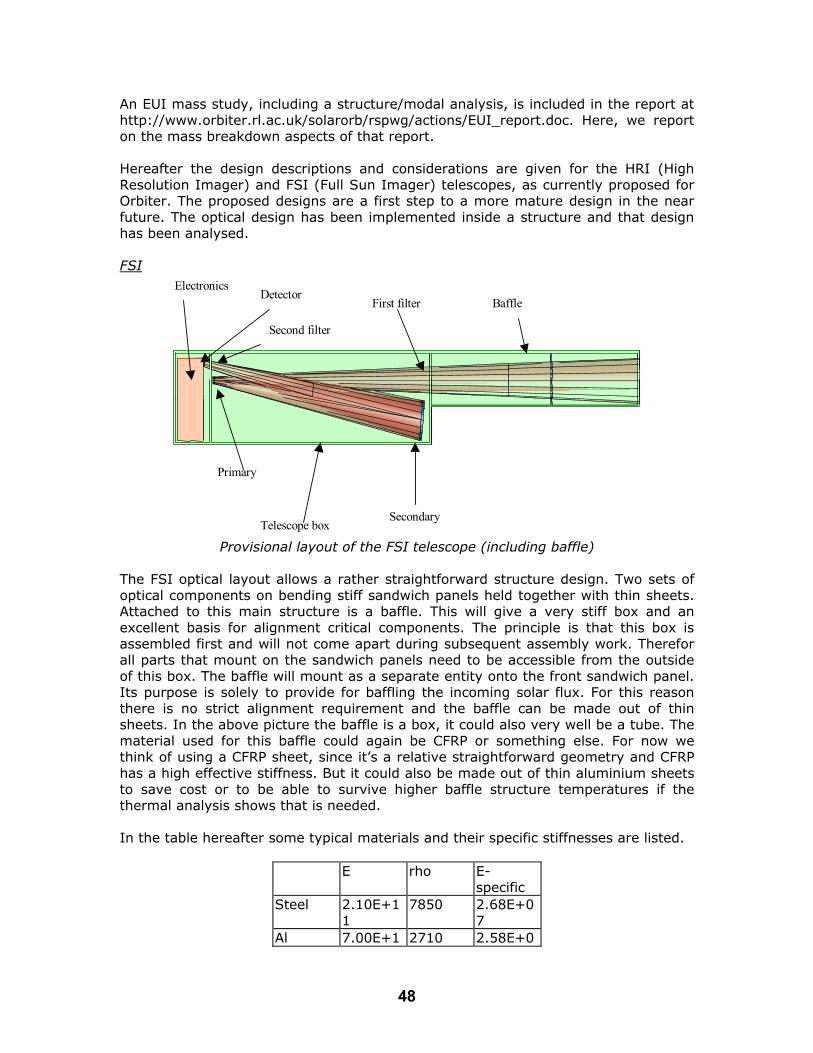
An EUI mass study, including a structure/modal analysis, is included in the report at http://www.orbiter.rl.ac.uk/solarorb/rspwg/actions/EUI_report.doc. Here, we report on the mass breakdown aspects of that report. Hereafter the design descriptions and considerations are given for the HRI (High Resolution Imager) and FSI (Full Sun Imager) telescopes, as currently proposed for Orbiter. The proposed designs are a first step to a more mature design in the near future. The optical design has been implemented inside a structure and that design has been analysed.
ElectronicsDetector
Primary
Second filter
Telescope boxSecondary
BaffleFirst filter
FSI
Provisional layout of the FSI telescope (including baffle) The FSI optical layout allows a rather straightforward structure design. Two sets of optical components on bending stiff sandwich panels held together with thin sheets. Attached to this main structure is a baffle. This will give a very stiff box and an excellent basis for alignment critical components. The principle is that this box is assembled first and will not come apart during subsequent assembly work. Therefor all parts that mount on the sandwich panels need to be accessible from the outside of this box. The baffle will mount as a separate entity onto the front sandwich panel. Its purpose is solely to provide for baffling the incoming solar flux. For this reason there is no strict alignment requirement and the baffle can be made out of thin sheets. In the above picture the baffle is a box, it could also very well be a tube. The material used for this baffle could again be CFRP or something else. For now we think of using a CFRP sheet, since it’s a relative straightforward geometry and CFRP has a high effective stiffness. But it could also be made out of thin aluminium sheets to save cost or to be able to survive higher baffle structure temperatures if the thermal analysis shows that is needed. In the table hereafter some typical materials and their specific stiffnesses are listed.
E rho E-specific
Steel 2.10E+11
7850 2.68E+07
Al 7.00E+1 2710 2.58E+0
48

0 7 CFRP 1.20E+1
1 1800 6.67E+0
7 Ti 1.10E+1
1 4600 2.39E+0
7 CFRP (quasi-isotropic) has the best specific stiffness by far compared to steel, aluminium or titanium. Making it the best choice for light weight construction if it can be used as a sheet. For parts that are stressed in three dimensions it is less suitable and a metal is a better choice. CFRP also has the lowest coefficient of thermal expansion. Using CFRP in this particular configuration would benefit from a quasi-istropic layup. The effective coeficient of thermal expansion would be the same (in plane) in all directions. Our experience with M55 is that the expansion for such a lay-up is lower than 0.5x10⁻⁶ m/m-°C at room temperature. For a structure like this a temperature variation of 10 °C would yield a worst case relative displacement for the optical components of 4 micro-meter. The detector is mounted of the back sandwich panel and is pictured inside an enclosure. This is not necessary, it could also be ‘outside’ the telescope. Without the box structure extended around it. This would expose the electronics box directly to space, but using a thermal blanket the temperature fluctuation could be damped sufficiently.
1450
180
280
Overall dimensions in mm
Sandwich panels
The overall telescope assembly will fit inside the payload bay as the current design stands. Because of the extreme thermal environment of the spacecraft the thermal coupling with the spacecraft needs to be considered carefully. The coupling is via radiation of the payload bay and via conduction through the mounting points. We need to study the heat flow between both in the extreme thermal cases. For now it is assumed that the telescope box will be isolated from its environment as much as possible using thermal blankets. And also assuming the spacecraft will shadow the telescope at all times. A radiator panel is baseline to control the temperature of the detector and possibly the mirrors. The entry baffle will effectively serve as a black body absorber. Unless the filter is moved from its current location on the front panel to the entry
49

opening of the baffle. All in all the incoming heat flux is in the order of 500 W. It may be necessary to thermally isolate the baffle from the box. This can be done by using a bi-pod mounting on the sandwich panel, with the legs designed such to minimise thermal conduction and thermo-elastic loads from the shrinking and expanding baffle as the spacecraft cycles through its orbit. This is currently baseline. The mounting points of the telescope will be located at the edge of the sandwich panels. Two points at the edge/corner of the rear panel and one at the edge/centre of the front panel. The mounting will be statically determined to minimise deformation of the telescope via its interface with the spacecraft.
Following the above described baseline the mass budget for this telescope is tabulated. FSI Dimensions in mm and kg Telescope box
Length width Thickness mass [kg]
number total Sub
Bottom-top
785 280 0.36 0.142 2 0.284
Sides 785 180 0.36 0.092 2 0.184 Front panel
280 180 23 0.112 1 0.112
Rear panel
280 180 23 0.152 1 0.152
Stiffeners 280 25 0.36 0.021 14 0.294 Stiffeners 180 25 0.36 0.014 14 0.196 Fasteners 0.002 168 0.336 1.55 Baffle Length width Thickness mass
[kg] number total
Bottom-top
665 180 0.36 0.078 2 0.156
Sides 665 180 0.36 0.078 2 0.156 1st bulkh. 190 190 0.36 0.005 1 0.005 2nd bulkh.
190 190 0.36 0.009 1 0.009
Stiffeners 180 25 0.36 0.014 24 0.336 Fasteners 0.002 144 0.288 0.94 Total for CFRP part of structure
2.491
mass
[kg] number total
Mounting brackets of telescope
0.2 3 0.6
Mounting brackets for electronics box 0.15 4 0.6 Mounting brackets for baffle 0.2 3 0.6 Electronics box 2 1 2 Detector 0.2 2 0.4
50

4.2 Radius Thicknes
s Volume mass
[kg]
Primary mirror
10 4 1257 0.006 1 0.006
Secondary mirror
60 15 169646 0.848 1 0.848
0.855
Mirror supports and actuators Primary mirror 0.2 1 0.2 Secondary mirror 0.6 1 0.6 0.8 Thermal blanket 0.5 Thermal radiator 1.7 2.2 Total mass (excluding uncertainty) 10.5 Uncertainty (20%) 2.1 Total mass including uncertainty
12.7
HRI
sandwich panelsandwich panel
primary electronics box
field stop
secondary Provisional layout of the HRI telescope (just 1)
The HRI consists out of three telescopes, all with the same layout and dimensions but with different optics (filters). Above the basic layout of one of the HRI telescopes is pictured. The HRI is different from the FSI in that the current optical design does not allow for the fairly simple layout as used for the FSI telescope. In the original HRI first cut optical layout a long baffle was foreseen. However this may not be needed. In the structural design of the HRI telescope the same principles hold as for the FSI, the only difference being the filter, field stop and primary mirror location. It seems logical to combine the three individual HRI telescopes into one structure. This would save mass and assist the co-alignment of the three individual telescopes. It would also be best to combine the 3 electronics boxes into one box. There was no time to design such a telescope. It would also require change in the optical design. For the suspension and thermal design the same principles hold as for FSI. The location of the filter, inside the HRI structure is from a thermal point of view sub
51

optimal. Better would be to move the filter to the entry aperture of the telescope. Blocking most of the incoming solar flux and minimising the telescope temperature.
Overall dimensions in mm
110
230
HRI Dimensions in mm and kg Telescope box
Length width Thickness
mass [kg]
number total Sub
Bottom-top
1450 20 0.36 0.019 2 0.038
Baffle panels
1500 120 0.36 0.117 2 0.233
Sides 1450 120 0.36 0.113 2 0.226 Front panel
220 120 23 0.080 1 0.080
Sec. Suppot
220 120 23 0.080 1 0.080
Filter sup.
220 120 23 0.080 1 0.080
Rear panel
220 120 23 0.080 1 0.080
Stiffeners
220 25 0.36 0.004 12 0.043
Stiffeners
220 25 0.36 0.004 0 0.000
Fasteners
0.002 105.6 0.211
1.068 Total for CFRP part of structure
1.068
mass
[kg] number total
Mounting brackets of 0.2 3 0.6
52

telescope Mounting brackets for electronics box 0.15 4 0.6 Mounting brackets for baffle 0.2 3 0.6 Electronics box 1.5 1 1.5 Detector 0.2 2 0.4 3.7 Radius thickness Volume mass
[kg]
Primary mirror
10 4 1257 0.006 1 0.006
Secondary mirror
15 4 2827 0.014 1 0.014
0.020 Mirror supports and actuators
Primary mirror 0.2 1 0.2 Secondary mirror 0.5 1 0.5 0.700 Thermal blanket 0.5 Thermal radiator 1.7 2.2 Total mass (excluding uncertainty) 7.7 Uncertainty (20%) 1.54 Total mass including uncertainty 9.2 Overall conclusions: Both telescope designs will fit inside the current available payload envelope. The length of the HRI is critical in the sense that it only just fits within the payload bay. For more confidence we need to study more detailed geometry of optics and electronics boxes. The overall optical design of the telescope can perhaps be optimised a bit more if needed. The design of the telescopes is extremely lightweight, we need to look in more detail into the stressing of the proposed telescope designs. The mass estimates for the two components are 9.2 kg for the HRI and 12.7 for the FSI. The original plans (July 2000 proposal) included 3 HRI telescopes and one FSI, making a total mass of 40.3 kg. This includes a 20% margin (8 kg), and the target mass was 36 kg. Reference: EUI_report.doc at PWG Web site. Action ID Number: 1.4 - UVC Responsible Working Group Member: Silvano Fineschi Action: UVC Mass breakdown study The mass of the strawman Ultraviolet and Visible-light Coronagraph (UVC) has been derived using some hypotheses. The optical bench is assumed to be made of CFRP
53

sandwich, while the elements supports could be made by a low coefficient of thermal expansion (CTE) metallic material, e.g. invar. The materials selection is an important topic of this study because of the harsh environment where the instrument will be operating (i.e., launch vibrations, large thermal gradients, dust, radiation, etc.) and the scientific requirements. The scientific requirements should be carefully addressed in order to optimise the mechanical and thermal design via suitable materials selection; the optical errors budget analysis is deemed essential in the optical bench material trade-off. The secondary structure (i.e. the box surrounding cover) could be made-up by joining together five thin panels that, in turn, are in connected to the bench. The hypothesis for the mass budget is to use thin sandwich panels, since the purpose of this secondary structure is only to enclose the instrument (in order to control the stray-light) and (probably) to take away heat from sun-disk rejection mirror (M0) that prevents the direct sunlight from entering the telescope. This second function can imply the use of thermal conducting stripes or heat pipes, which may be better placed in a honeycomb structure (that is anyway lighter than Al). These evaluations are typically the result of a complete thermal analysis (which ought to be done taking into consideration also the whole spacecraft thermal control approach). The coronagraph instrument box overall dimensions are {1.2 x 0.55 x 0.3} m3 (cf. Fig. 1, and Fineschi, et al., 2001); the optical bench thickness is assumed to be 40 mm (included in the reported 3rd dimension).
Figure 2 Configuration of the coronagraph box, and internal views. The telescope mirrors are assumed to be made of Zerodur. Because of its good thermal conductivity, Silicon Carbide (SiC) is the material selected for sun-disk rejection mirror (M0). Also the mirror supporting structure is supposed to be made of SiC, as this material can be used both for mirror substrates and for structural parts. The UVC mass breakdown obtained with all these assumptions on the materials for the structure and the optics is summarized in Table 1.
Component Mass (kg) Structure 6.6Thermal control hardware 0.6
54

Stepper motors 0.3Optics 2 Mechanisms 1Detectors (2) 2CPU & Interface 2DC/DC converter 1ADC 1Data compressor 1Motor drive 2
Electronic housing 4.2
TOTAL instrument 23.7
Table 1. UVC mass breakdowm Conclusion: The estimated budget of the total UVC mass is 23.7 kg. This is inclusive of the electronic housing that has the shielding necessary for surviving the environment of the Solar Orbiter Mission. It is worth pointing out that the obtained mass value is based on standard hypotheses about the structure: no attempt of minimizing the mass has been done. Mass savings are certainly possible, and it is suggested that the following actions be considered by the Solar Orbiter Project and by any proposing UVC team to contain the coronagraph and the payload mass budget: - The Project to consider the possibility for sets of remote sensing instruments to
share the same electronic housing. This would consolidate the weight of the shielding;
- Proposing UVC teams to consider using the spacecraft (S/C) shield as the
coronagraph’s external occulter. This would result in same mass saving by reducing part of the coronagraph structure necessary to hold the external occulter and connect it to the telescope.
Reference: Fineschi, S., Antonucci, E., Gardiol, D., Da Deppo, V., Naletto, G., Romoli, M., Cacciani., A., Malvezzi, M., 2001, “Extended UV Corona Imaging from the Solar Orbiter: The Ultraviolet and Visible-light Coronagraph,” ESA SP-493, pp. 217-222. Action ID Number: 1.4 - VIM Responsible Working Group Member: Valentin Martínez Pillet Action: VIM Mass Breakdown Study The mass breakdown of VIM described here is based on past experience in other space instruments like SOHO/SUMER (MPAe, see Wilhelm et al. 1995), ground instruments like TESOS (KIS, see Kentischer et al. 1998) and TIP-LPSP polarimeters (IAC, see Martínez Pillet 1999). Relevant to several aspects of the mass budget is the
55

on-going development of the SUNRISE stratospheric balloon (see Solanki et al., 2002), which contains an optical instrument similar to VIM. The key aspects of the mass budget are: ultra lightweight C/SiC mirror for the HRT, all ceramic structure, optics with no moving parts (liquid crystal based polarization modulator, LiNbO3 etalons) and the use of an APS type detector and ASIC controller that perform a great deal of the functions needed to convert photons to bits. It considers the following subsystems High Resolution Telescope + Magnetograph (total of 10.1 Kg) Mirrors and Structure 2.8 Kg Pre-filter 0.1 Kg Polarization Modulator 0.4 Kg HRT folding mirror 0.1 Kg Tip-Tilt mirror 0.8 Kg Re-imaging system 0.4 Kg Etalons, oven and elect. 2.5 Kg VIM focus mechanism 0.5 Kg HRT/FDT selector 0.3 Kg CMOS-APS detector 1.2 Kg Harness 1.0 Kg Full Disk Telescope + Image Stabilisation (total of 3.1 Kg) Prefilter 0.1 Kg Lenses and Structure 0.6 Kg Polarization Modulator 0.4 Kg FDT folding mirror 0.1 Kg Tip-Tilt mirror 0.8 Kg Cube Beam-splitter 0.2 Kg ISS Lens 0.1 Kg ISS detector and elect. 0.5 Kg Harness 0.3 Kg VIM Thermal & structural (total of 13.8 Kg) VIM enclosures 6.5 Kg VIM thermal subsystem 3.5 Kg VIM door mechanism 0.8 Kg VIM electronics 3.0 Kg VIM Margin (10 % of above) 3.0 Kg TOTAL VIM MASS 30 kg The above mass breakdown considers the strawman VIM proposed in the assessment study to ESA. In this case, the HRT is an open Gregorian telescope with a light rejection system (heat stop) that sends the light sideways. The Astrium study on the thermal feasibility of the VIM HRT telescope considered this configuration (but did not recommend it). The total mass (with a 25 % margin) allocated in the study for this configuration was 11.4 Kg, including one radiator for the heat stop and one for
56

M1. This number compares favorably with the total of 12.8 Kg assigned above to the mirror and structure, enclosures and thermal subsystem added together. The Astrium study favors a concept that uses an entrance window to relax the thermal handling of the HRT. This extra window weights 1.4 Kg. But in this case there are savings on the thermal subsystem, as the telescope would use no radiators. The total mass associated to this recommended solution is estimated to be 10.8 Kg, which is, again, below the allocated 12.8 Kg. Most critical of all the numbers is currently the allocation for structural subsystems like the enclosure of the HRT. Further progress on the mass allocation requires coordinated work at instrument and payload bay level, including the verification of the spacecraft thermal concept and payload distribution. We want to emphasize that the increase in the VIM mass from the assessment study value of 26 kg to the current 30 kg is due to including more realistic estimates of the needs in the structural and thermal aspects of the instrument. Conclusion: The estimated VIM mass is 30 kg, with a 10 % margin. The Astrium study shows that this is a realistic estimate for a number of different concepts that could be adopted for the HRT. Further confirmation of this value depends on structural and thermal analysis that must include a description of the location of the instrument within the payload bay and a thermal model of the spacecraft itself. References: Astrium, Solar Orbiter VIM Telescope, 2003, Consulting Assesment Kentischer, T. et al., 1998, A&A, 340, 569 Martínez Pillet, V. et al., 1999, ASP Conf Series, Vol. 183, 264 Solanki, S. et al., 2002, ESA SP-505, 27 Wilhelm, K. et al., 1995, Solar Physics, 162, 189 Action ID Number: 1.4 - RAD Responsible Working Group Member: Isabelle Rüedi Action: RAD Mass breakdown study The mass breakdown of a RAD instrument has been studied. The instrument consists of an aluminum housing, a 4-channel radiometer mainly made out of aluminum. An aperture wheel holding 3 apertures of different diameter is provided for each channel in order to cope with the varying level of irradiance throughout the orbit and serves at the same time as shutter. The mass breakdown is as follows: Empty package 2.5 kg (including a front cover wheel/door and motor) Radiometer 2.0 kg (including apertures wheels and their motors) Electronic/logic 1.2 kg DC/DC 0.9 kg Harness 0.14 kg (0.04kg +0.1kg/m) TOTAL 6.74 kg
57

Note that no sun-shield was included in this study since it was assumed that it will be provided by the spacecraft. Conclusion: This preliminary study shows that the weight necessary to build a radiometer for Solar Orbiter is around 6.7 kg. Some weight could be saved by using a power supply in common with other instruments. Action ID Number: 1.4 - STIX Responsible Working Group Member: Bib Lin & Gordon Hurford Action: STIX Mass breakdown study The estimated mass of STIX is 4 kg plus 1 kg for contingency. This is based on a well-calculated mass of 0.25 kg for the grids, 0.2 kg for the sunshade and 1 kg each for the metering structure, detectors and electronics and 0.5 kg for miscellaneous subsystems. An additional 25% (1 kg) is added for contingency to reach the 5 kg value quoted in the PDD data sheet. Action ID Number: 1.4 - HI Responsible Working Group Member: Clarence Korendyke Action: HI Mass breakdown study The estimated mass of the HI instrument is given as 5 kg, tabulated below:
Unit Mass (kg) Telescope 1.29 Camera electronics box 0.5 Structure 1.8 Kinematic structure mounts 0.3 Baffle cover assembly (door) 0.754 Contamination components 0.150 Alignment cube 0.013 Margin 0.2 TOTAL 5.007
The current HI PDD calls for two HI units, mounted on each side of the spacecraft, making a total mass of 10.014 kg. Action ID Number: 1.5 EUS Responsible Working Group Member: Richard Harrison Action: EUS Power breakdown study With several options on the table for an EUS instrument, it is not possible to produce an accurate power breakdown for the instrument. Thus, we have only a basic idea of the required power level. We can compare to existing instrumentation. For example, the CDS instrument has an average power value at 58 W. This is a 100 kg instrument with a pointing mechanism (two actuators), two spectrometers, with two sets of detectors (5 in all), a slit mechanism, a scan mirror mechanism, two doors, and heaters. The EUS will most likely have 1-2 detectors, no pointing system, one door, a mirror mechanism and a slit scanning mechanism, and heaters. It is a far
58

simpler instrument in terms of numbers of mechanisms and detectors, though the thermal control is more complex. However, most of the thermal control will be through passive processes, and we anticipate the instrument (optical surfaces) running hot. The best current estimate is to compare the EUS instrument with the NEXUS instrument proposed for the NASA SDO mission. This had an average power consumption of 56 W, including a margin of 5 W. This is a similar instrument to the EUS concept, but the EUS would include 1-2 detectors instead of the 3 of NEXUS, and the proposed APS detectors would require less power than the NEXUS CCD devices. Considerations like this bring the rough power estimate for EUS to something like 40 W, without margin, but the power consideration is dependent on the final design concept chosen. The EUS average power given in the July 2000 proposal was 25 W and in the Pre-Assessment it was 30 W. Thus, the current estimates must be trimmed by about 10 W at least during the optimisation of the instrument design to achieve such a figure. This is not regarded as insurmountable, but refinement of the power breakdown cannot be considered until the optical design has been fixed in some detail. However, 30 W is considered to be a realistic target. Action ID Number: 1.5 - EUI Responsible Working Group Member: J-M. Defise, D. Hassler, L. Harra Action: EUI Power Breakdown Study The strawman EUI instrument consists of a Full Sun Imager and a High Resolution Imager (FSI and HRI). The average power for the FSI is given as 3W, with 17 W to the 3 HRI systems (essentially detectors, shared electronics and DPU). For a given telescope, we anticipate a constant power requirement of about 4 W for the cycling (power on, integration, dump to memory…). Reasonable margins, plus power for pointing, takes this to 5 W. Thus, for three HRI telescopes, working simultaneously, this is 15 W for basic functions, to which we add 2 W for data compression and telemetering by a common DPU. Sequential observations would lead to a power saving. However, the baseline power is given as 20 W for the EUI. Action ID Number: 1.5 - UVC Responsible Working Group Member: Silvano Fineschi Action: UVC Power breakdown study The power budget of the strawman Ultraviolet and Visible-light Coronagraph (UVC) has been estimated for the different operational modes described below. In order to minimize power consumption, three basic Operative modes (OpM) have been defined, plus a Standby mode:
The three basic OpMs are:
• Data Acquisition; • Data Compression; • Instrument Configuration.
59

Plus: • Standby Mode;
In each of these OpM, only the necessary components are supplied with power. In standby mode, the power is supplied to only three components: DC/DC converter, Power interface and CPU module. These components are also powered in all the other OpMs. During Data Acquisition, at least one detector with the related electronics and ADC needs power. Data Acquisition implies both on-source exposure and frame transfer to the memory bank. During Data Compression the RICE Compressor board is also powered. In Instrument Configuration mode, all the actions are performed to configure the instrument (filter selection, doors opening/closing). In all the three OpMs the power consumption of the DC/DC converter is higher because of the increased total supply requirement. The electronics box considered is that of the Standard Payload Computer (SPLC), in its 5-slot configuration. A description of the characteristics of the 5 boards in the relative slot is given in Table 1.
Electronics Component in the Board Power Consumption (W)
Analog/Digital Converter (2 units) (ILC Data Device Corporation)
5 (1 ADC)
Stepper Motor Control (2 channlel) (Hytec Electronics Ltd. VMC series, Etel SA)
5 (1 channel)
DC/DC Converter (ILC Data Device Corporation)
8
SPLC (Erc32 + 1533 bus interface) (Daimler-Benz Aerospace)
12 (CPU module) + 7 (1533 interface)
Packetising RICE Compressor Board (SAAb-ERICSSON Space, PRCB)
10
Table 1. Characteristics of the 5 boards in the UVC electronics box. The UVC power budget can be derived from the consumption of each electronics component in the four instrument modes. This is given in Table 2.
UVI Power Budget for each Instrument Mode (W) Active Component Stand-by D. Acquisition D. Compression I. Configuration
CPU & Interface 19 19 19 19 DC/DC converter 5 6 6 6
60
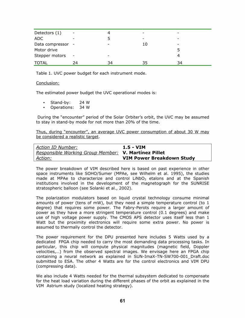
Detectors (1) - 4 - - ADC - 5 - - Data compressor - - 10 - Motor drive 5 Stepper motors - - 4
TOTAL 24 34 35 34 Table 1. UVC power budget for each instrument mode. Conclusion: The estimated power budget the UVC operational modes is:
• Stand-by: 24 W • Operations: 34 W
During the “encounter” period of the Solar Orbiter’s orbit, the UVC may be assumed to stay in stand-by mode for not more than 20% of the time. Thus, during “encounter”, an average UVC power consumption of about 30 W may be considered a realistic target. Action ID Number: 1.5 - VIM Responsible Working Group Member: V. Martínez Pillet Action: VIM Power Breakdown Study The power breakdown of VIM described here is based on past experience in other space instruments like SOHO/Sumer (MPAe, see Wilhelm et al. 1995), the studies made at MPAe to characterize and control LiNbO3 etalons and at the Spanish institutions involved in the development of the magnetograph for the SUNRISE stratospheric balloon (see Solanki et al., 2002). The polarization modulators based on liquid crystal technology consume minimal amounts of power (tens of mW), but they need a simple temperature control (to 1 degree) that requires some power. The Fabry-Perots require a larger amount of power as they have a more stringent temperature control (0.1 degrees) and make use of high voltage power supply. The CMOS APS detector uses itself less than 1 Watt but the proximity electronics will require some extra power. No power is assumed to thermally control the detector. The power requirement for the DPU presented here includes 5 Watts used by a dedicated FPGA chip needed to carry the most demanding data processing tasks. In particular, this chip will compute physical magnitudes (magnetic field, Doppler velocities,…) from the observed spectral images. We envisage here an FPGA chip containing a neural network as explained in SUN-ImaX-TN-SW700-001_Draft.doc submitted to ESA. The other 4 Watts are for the control electronics and VIM DPU (compressing data). We also include 4 Watts needed for the thermal subsystem dedicated to compensate for the heat load variation during the different phases of the orbit as explained in the VIM Astrium study (localized heating strategy).
61
These two aspects have increased the power requirements assigned to VIM (25 Watts in the assessment study) to an amount of 34 Watts including 10 % margin. We note that in the ESTEC pre-assessment study of the Solar Orbiter, the magnetograph had assigned a value of 35 Watts. VIM also has a number of mechanism (focus, HRT/FDT selector) that are not listed here as they will be used only outside observing windows, when a number of devices will be off and thus being able to provide the required power. VIM Power requirements Polarization Modulator 2 Watts Image Stabilisation System 4 Watts Fabry-Perots, oven and elect. 8 Watts CMOS-APS detector 4 Watts DPU and control electronics 9 Watts Thermal subsystem 4 Watts VIM Margin (10 % of above) 3 Watts TOTAL 34 Watts Conclusion: VIM requires 34 Watts for its operation. The increase with respect to previously estimated values is explained by the demanding data processing levels needed and the thermal regulation subsystem. While the later is probably unavoidable, the former (data processing levels) can be lowered (with an impact on science) offering some possible power savings (up to 5 Watts). References: Astrium, Solar Orbiter VIM Telescope, 2003, Consulting Assesment Solanki, S. et al., 2002, ESA SP-505, 27 SUN-ImaX-TN-SW700-001_Draft.doc SUNRISE-ImaX technical note on VIM data processing needs (available through [email protected]). Wilhelm, K. et al., 1995, Solar Physics, 162, 189 Action ID Number: 1.5 - RAD Responsible Working Group Member: Isabelle Rüedi Action: RAD Power breakdown study The RAD power breakdown is based on experience in other space projects such as VIRGO/SOHO and SOVIM/ISS. It assumes a constant thermal environment provided by the satellite. The RAD power breakdown is tabulated in detail at http://www.orbiter.rl.ac.uk/solarorb/rspwg/actions/RAD_power_report.doc. The table gives the details of the normal operation breakdown which corresponds to 5.14 W. Another 2.24W will be necessary to keep the instrument at a constant temperature throughout the orbit. These values correspond to a total of 7.38 W including 10% contingency. The operation of the shutter/aperture wheels will need additional power. This value is strongly dependent on the types of motors used. Using one of the presently available motor types this would amount to 13W during 0.8s/1minute. These values will need
62

to be refined depending on the type of motors which will actually be used, in particular if such a power peak is a problem. Conclusion: RAD will need 7.38 W for its operation plus some power to activate the aperture/shutter wheels. This latter power will be dependent on the type of motors used (f.ex 13W during 0.8s/1minute). Note that this analysis assumes a constant thermal environment provided by the satellite. Action ID Number: 1.5 - STIX Responsible Working Group Member: Bob Lin & Gordon Hurford Action: STIX Power breakdown study The current estimate for the power consumption of STIX is 4 Watt (average and peak) with a 1 Watt mode in standby. Action ID Number: 1.5 - HI Responsible Working Group Member: Clarence Korendyke Action: HI Power breakdown study The average electronic power is estimated to be 1 Watt, with a peak power of 2 Watt, assuming spacecraft provided sequencing and power conditioning. A stand-by power of 0.2 W is assumed, with a heater power of 3 Watt (per HI unit). If there are two units, the total heater power if 6 Watt. Action ID Number: 1.6 Responsible Working Group Member: Udo Schühle, Luca Poletto &
Clarence Korendyke Action: Study of the integrity of optical components, filters and multilayers under the extreme conditions of the Solar Orbiter mission. The large thermal and particle variations of the Solar Orbiter environment require a detailed consideration of the potential degradation of optical surfaces and filters. This is considered to be an area for major study. Thus, a detailed report has been written by Schühle, Poletto and Korendyke, and is included as Appendix 1. It details required tests on optical components and has been passed to the ESTEC engineers. It is recommended that such tests be generated or supported by ESA, in preparation for the Solar Orbiter mission. Action ID Number: 2.2 Responsible Working Group Member: Valentín Martínez Pillet Action: To study the suitability of Liquid Crystal Variable Retarders for polarization modulation on the Visible-light Imaging Magnetograph (VIM). VIM measures the magnetic field on the Sun through the detection of the polarization state of the light. Doppler measurements may use as well polarization optics. Thus,
63

VIM needs a polarization modulator. Traditionally this has been made by using wave-plates (optical retarders) that are mounted on a rotating mechanism. Polarization modulation is, then, achieved by mechanical rotations. These continuous or stepped rotations need excessive mass (compared to the retarder weight itself) and are power consuming. Also the devices must show no mechanical degradation (bearing degradation is a concern) during the whole mission time frame. Liquid Crystal Variable Retarders (LCVRs) offer an interesting alternative as polarization modulators. The well developed Liquid Crystal Display (LCD) technology in use in a myriad of applications can be used as a polarization modulation system. Two types of LCVRs are available for this purpose, those based on nematic materials (change of birrefringe) or ferroelectric materials (change in orientation). Here, we refer them generically as LCVRs and make no further distinction. LCVRs are retarders whose properties can be changed electronically by means of a simple (few volts) driving signals. The response times are in the range of tens of milliseconds or better. LCVRs are easy to synchronize to a detector readout due to their electro-optical nature, simplifying the instrument control. No moving parts are needed, offering a clear advantage for a space mission. Their power consumption is negligible and only the driving electronics (which can be efficiently designed for low consumption) should be considered. In addition they do not need heavy mechanical mountings. They are commercially available today and products manufactured 7 years ago are still working under specs (IAC experience). They have been used for ground polarimeters (Martínez Pillet et al., 1999) with a satisfactory performance and in stratospheric balloon experiments (Flare Genesis Experiment, Bernasconi et al., 2000) working in vacuum. LCVRs main disadvantage is their sensitivity to UV light which causes malfunctioning of the devices. For an experiment like VIM, where UV light will be avoided by all means way before reaching the LCVRs, this should not be a real problem. LCVRs need to be temperature controlled to within 1 °C only. LCVRs have been space qualified to various degrees by different teams. Here we show present levels of characterization (integrity and functionality in some cases) of LCVRs produced by Meadowlark (Colorado) as made by EADS-CASA (see report for more details): Vacuum integrity: 10-5 mbar Heating/Cooling: [-80, 85] °C Vibrations: 20-2000 Hz up to 7 g Launch Shock: 15 g in 10 ms Outgassing: ESA standard PSS-01-705 Ionizing γ radiation: up 17 Krad Ionizing e- radiation: up to 2 Mrad (source Meadolwark Optics) UV exposures: up to 50 ESH All of these characteristics are positive, except the last one as commented before. IAC has been since 2001 collaborating with an Italo-Spanish LCD company (TECDIS Display, www.tecdis.com) to produce LCVRs for use in the stratospheric Antarctica balloon experiment SUNRISE. IAC is PI institution of a VIM-like instrument, the Imaging Magnetograph eXperiment ImaX, for the SUNRISE project that will produce
64

polarization modulation using the LCVRs produced under the collaboration IAC+TECDIS (funded by the Spanish space program). TECDIS contribute with all the LCD experience an IAC sets the requirements for optical quality of the devices (λ/4 is expected to be achieved using fused silica substrates). Prototypes for the ImaX instrument have been produced by TECDIS and calibrated at IAC with most satisfactory results. Final prototypes with the specified optical quality will be produced before the end of the year. IAC together with INTA (Spain) plan to carry out the qualification for the balloon experiment in year 2003. LCVRs need further studies for use in an instrument like VIM. The radiation levels the spacecraft will encounter should be considered. Functionality under the cruise + nominal/extended mission conditions should be studied. No LCVR has been in vacuum for a long period of time and put to work after a large lapse of time. But the technology seems to be ready for a full characterization (in particular, response to small amounts of UV light). This technology is particularly useful for a space mission which has very strong constrains of mass, power and complexity. We note that the UVC instrument is also considering the use of LCVRs in his visible part. Conclusion: LCVRs technology (basically LCD technology) has been proven on ground instrument and qualified for a suite of space applications. This technology offers the possibility of producing large mass and power savings compared to mechanically driven devices. It also offers a more simple solution for synchronization purposes than rotating devices. LCVRs are commercially available and are being manufactured for optical and space programs in several parts of the world. Since LCVR technology may be required for UVC as well as VIM, we recommend that ESA considers this technology for a study to assess and confirm its use for Solar Orbiter, and thus paving the way for future space applications. References: Bernasconi, P., Rust, D., et al., 2000, Proc. SPIE 4014, 214 EADS-CASA CAS-LCV-RPT-0002 Martínez Pillet, V. Collados, M. et al., 1999, ASP Conference Series #183, ISBN:1-58381-009-9, p.264 Action ID Number: 2.3 Responsible Working Group Member: Valentín Martínez Pillet Action: VIM Stabilisation Sensor Typical helioseismology measurements require velocity errors of 10 m/s. Velocity errors of this magnitude are produced by image motion during the exposures used to determine the Doppler shifts. This error reference is adopted here. To know how much this implies in terms of real image motion, we use the following estimates: in a typical distance of 1000 km one finds points on the sun with velocities that differ by as much as 4 km/s (near an intergranular boundary). This implies that a 10 m/s change is produced over a distance of 2.5 km only. Near perihelion this corresponds to a displacement of the image by 0.02 arcsec. Helioseismology thus requires stability over a typical spectral line scan lasting 10 seconds of about 0.02 arcsec to limit velocity errors due to image motion.
65

This image stability corresponds well with the 10-3 sensitivity expected for the polarization measurements (4 G BL and 80 G for BT). Figure 1 shows the differential signal produced from two intensity spectra shifted by the same 10 m/s displacement. This spurious signal is readily interpreted by a single beam polarimeter as a polarization signal. As it is apparent from this Fig. The residual signals produced are about a factor two larger than the required 10-3. To make these signals two times smaller, we adopt as pointing stability requirement for VIM 0.01 arcsec (1σ) over a ten seconds period. VIM pixels are 0.25 arcsec which translates into a stability requirement of 0.04 pixels in 10 seconds.
Fig.1 Spurious polarization signal generated by displacing intensity spectra by 10
m/s. The AOCS of the spacecraft provides a pointing stability of 3 arcsec (3σ) over 15 minutes (TBC) with a TBD frequency spectrum. Although this provides a good starting pointing stability, an ISS is needed to ensure the required stability over smaller intervals of time. Ample experience has been obtained in recent years developing ISS for solar observations from space. Limb sensors have been successfully used in SOHO/MDI (Scherrer et al., 1995), TRACE (Handy et al., 1999) and are being built for STEREO, or developed for SDO (HMI and SHARPP). All of them are NASA funded payload. A full correlation tracker is included in the FPP of SOLAR-B (being made in Japan). Correlation trackers use (small) CCDs and make the ISS more complex than a limb sensor based system. We adopt a limb sensor as the basis for the VIM-Solar-Orbiter ISS. The wavefront sensor explained in the proposal for VIM will not be considered unless spacecraft resources increase significantly. A wavefront sensor would be most helpful to correct for thermally driven aberrations that will be much easier to handle in this way. In the absence of wavefront sensing, the thermal model of VIM will have to be carefully defined.
66

Fig.2 Scheme of VIM with the HRT and the FDT. The common M4 sending the light to
the filtergraph is the tip-tilt for the HRT and FDT. In the FDT a cube beamsplitter sends the light to the limb sensor with a folding mirror that acts as closed loop tip-
tilt. M4 tip-tilt should mimic the ISS Tip-Tilt. The two critical components of the ISS are the tip-tilt mirror and the limb sensor detectors. These are normally four photodiodes at 90 degrees from which the difference signal between opposite detectors provide the desired error signal. Some redundancy, provided by duplicated photodiodes, is desirable. Also the geometry of the detectors should be considered to accommodate full disk sizes at all orbital times (see AI 10.6 about the use of ISS far from perihelion). The tip-tilt mirror is typically a 3 piezoelectric transducer (PZT) actuator supporting a small mirror with bandwidths typically of up to 1 kHz. SOHO/MDI uses such a system in closed loop providing pointing stability of 0.02 arcsec in tens of seconds. The TRACE guider telescope (GT) uses the secondary for tip-tilt and reduces spacecraft pointing errors of 5 arcsec (3σ) in 10 s intervals to 0.1 arcsec (Fig. 8 in Zimbelman et al., 1996). The TRACE GT error signals are sent in the low frequency range, below 0.1 Hz, to the AOCS and higher frequencies, up to 50 Hz,to the tip-tilt (secondary) mirror. Only the error signal that is sent to the AOCS forms a closed loop system. The part sent to the tip-tilt mirror on the main telescope produces no correction of the image on the solar-limb photodiodes and, thus, forms an open-loop system. As it appears in the proposal, VIM Solar Orbiter has a Full Disk Telescope (FDT) and a High Resolution Telescope (HRT, see Fig. 2). The ISS explained here should stabilize the signal for both telescopes. We propose an ISS with two tip-tilt mirrors and only one limb sensor to save mass and power. Light at the nominal wavelength on the FDT (say red) is sent to the filtergraph during observations. We propose to locate a beamsplitter on the FDT path that sends other wavelengths (say green) to the limb sensor also with the help of a folding mirror. This folding mirror will be one
67
of the two tip-tilt mirrors. As it is in front of the limb sensor, it forms a closed loop system. Such a system can provide up to a factor 10 better pointing than, for example, the TRACE system. However this tip-tilt mirror has not yet stabilized the light transmitted through the beamsplitter at the FDT and that goes into the filtergraph. The stabilization will be provided by making the M4 mirror of the optical design also tip-tilt. As this mirror is shared between the FDT and the HRT it will stabilize both beams. The error signals of this second tip-tilt will be the same as those derived from the previous tip-tilt mirror located on the FDT using the same gains and offsets, if the observations are being made with the FDT itself. If the HRT is being used, corrected gains and offsets will be computed (due to the different spatial scales). As the error signal is being used by a tip-tilt different from the one that sends the light to the limb sensor, we call the system quasi-closed loop. Only through careful calibration and alignment of both tip-tilt mirrors can closed loop performance be ensured. We thus propose ground calibration of the two mirrors and to provide some calibration strategy in orbit (see AI 10.6 that further develops this idea for the rest of the spacecraft). The exact bandwidths needed for the full tip-tilt mirror depend on the jitter frequencies of the spacecraft+payload system. If no information is provided about this frequencies, we anticipate that an ISS reaching several tens Hz bandwidth with attenuation factors of 20-100 will be able to meet the stability requirements. This requirement can be relaxed only if more information about the jitter frequencies and amplitudes (as excited by motions in the spacecraft module and payload) is provided . Conclusion: VIM requires image stability of 0.01 arcsec over periods of 10 seconds. To guarantee this stability an ISS using a limb-sensor system should be provided. A full correlation tracker/wavefront sensor may not be needed. Information of the jitter frequency spectrum of the spacecraft/payload would be most helpful to provide the specifications on the limb sensor system. The ISS can be built using the full disk telescope and provide a quasi-closed loop to VIM in all observing modes and to other instruments requiring image stabilization. We anticipate the need to calibrate the response function of the ISS PZTs in orbit, before reaching perihelion observing phases. References: Handy B.N., et al., 1999, The Transition Region and Coronal Explorer, Solar Physics, 187, 229 Action ID Number: 2.4 Responsible Working Group Member: U. Schühle, A. Gandorfer Action: For the thermal and particle extremes, which Orbiter will encounter, how do we guarantee the required levels of cleanliness for VIM? For an instrument with reflecting optical components, the outgassing of condensable (organic) material is the major process leading to performance degradation. The varying thermal environment, as well as the changing apparent size of the Sun, increases the risk of redistribution of outgassing contaminants during the orbit. The deposition of these species on the optical components is extremely enhanced on cold
68

surfaces and on surfaces exposed to solar UV light and particle flux, leading to irreversible deposition by polymerization of the organic substances. It is thus mandatory to the design of the instrument to block the ultraviolet component of the spectrum on a clean, hot surface very early in the optical path. Otherwise cleanliness requirements for organic material would be prohibitive inside the optical housing. A front filter in the entrance aperture is a possible candidate for a solution. In any case, the instrument must be ultimately clean up to this surface, like a solar UV instrument. To avoid efficiently UV-enhanced polymerization, the UV filter must block all wavelengths shorter than 360 nm. Since the working passband of the instrument is in the visible, a UV blocking filter at the entrance aperture would be a preferred solution. However, the filter must be stable against the radiative flux and must be unpolarizing. These two requirements must be verified before this can be considered a final solution. Conclusion: In order to arrive at acceptable levels of cleanliness, the far UV radiation below 360nm must be blocked at the front aperture of the instrument. It must be verified that the blocking filter is stable against the solar UV radiation at 0.2 AU. Action ID Number: 2.6 Responsible Working Group Member: Achim Gandorfer Action: Entrance filter for VIM The VIM HRT was initially proposed as an open telescope with a free aperture of 25 cm in diameter. This report is discussing an alternative approach by using a narrow band-pass entrance filter. While thermal aspects of such a closed VIM telescope are discussed in detail in action items 1.1 (VIM) and 1.2 (VIM), this report focuses on the intrinsic feasibility of the window/filter only. This report is based on an industry study report by mso Jena [1]. The main goal of the entrance filter is to protect the telescope from excessive heat load during perihelion passes. It is therefore designed as a dielectric filter that reflects most of the incident solar spectrum back to the Sun, while transmitting only a narrow bass-band centered around the science wavelength (630nm, tbc). Window substrate: The window substrate should be made from fused silica. The main arguments for fused silica are the absence of UV fluorescence, the high internal transmittance between 200nm and 3 microns, the stability against particle radiation, the low coefficients for stress-induced birefringence, and the low thermal expansion coefficient. For reasons of mechanical stability the aspect ratio (diameter/thickness) of the filter should not exceed 20 and the edges of the window should be polished. Filter properties:
69

To achieve minimum internal absorption the filter is designed as an all-dielectric multilayer stack. All dielectric coatings are today deposited in a process called ion assisted deposition (IAD). This technique provides excellent durability and pass-band stability of the filter. It is widely used in manufacturing beam-splitter coatings for telecommunication applications. To protect the multilayer from excessive heat and from particles the multilayer stack is deposited on the inner surface of the entrance window. IAD coatings have thermal expansion coefficients below 10-6 /K and are stable against temperatures as high as 400O Celsius [2]. Transmission-, Reflection-, and Absorption of the window/filter system: It has been shown in [1] that the internal absorption in the filter can be as low as 0.5% (average) in a wavelength interval from 200nm to 3000nm, while reflectivity is above 98% in this wavelength band. To provide the necessary “observing window” a 10nm gap around 630nm has a reduced reflectivity of 15%, transmitting most of the science photons. The main contribution of energy input on the entrance window is thus not provided by the filter, but by absorption below 200nm and above 3000nm in the fused silica substrate! This is approximately 10% of the entire solar load. For a 25cm window this is 170W at 0.21 AU. Thermal properties of the window:
- Pass-band shift with temperature is not considered a problem due to the low thermal expansion of IAD layers (as described above)
- 170 W are absorbed in the window, which are radiated away by the window itself, which is almost black in thermal infrared. Even without additional thermal losses (assumption of complete thermally isolated mounting) a maximum temperature of 230 Celsius (at 0.21 AU) will be reached. This temperature is not considered a problem for the fused silica substrate, nor for the multilayer (Tmax=400o Celsius).
- However, to avoid large radial temperature gradients within the window the window should be thermally isolated from the mounting.
Angle of incidence: All dielectric multilayer coatings have limited acceptance angles. Deviations from the optimum incidence angle cause a wavelength shift of the band pass. For use in Solar Orbiter this is not considered a problem, since the science field of view is only very limited. For solar radiation coming from outside the science FOV the band pass is shifted, but the overall reflectivity is still at its high value [1]. Conclusion: With current technology there are no principle objections against a narrowband passband filter for VIM. However, as in all Solar Orbiter instruments relying on multilayer coatings a thorough analysis of long term stability of IAD coatings against temperature and particle radiation should be initiated.
70
References: 1. Machbarkeitsstudie Sonnenfilter. Mso Jena. Jena 2003 2. Zoeller, A., Goetzelmann, R., Matl, K., Cushing, D.: Temperature stable bandpass filters deposited with plasma ion-assisted deposition, Appl. Opt. 35, 5609, 1996. Action ID Number: 3.1 Responsible Working Group Member: L. Poletto, R. Harrison, U. Schühle Action: Optics contamination under high irradiation level, in particular for EUS Under high irradiation, particularly in the ultraviolet, any contaminant deposited on an optical surface, even in very minute amounts, polymerizes, so the reflectivity of the surface drastically decreases. This effect is well known for synchrotron radiation optics as well as for some space instruments, but has been well avoided by the SOHO UV/EUV instruments. The degree to which the reflectivity decreases depends on the irradiation exposure and on the partial pressure of the contaminant. However, for Solar Orbiter the situation is more difficult than it was for SOHO; due to the changing distance from the Sun, the level of UV irradiation will be higher and the thermal environment more variable. Even with the most stringent procedures in the handling and assembling of the optical components, under the extreme irradiation conditions at 0.2 AU, there is a risk of a serious rapid degradation of the reflectivity, especially in the EUV. The variable thermal environment during the orbit makes evaporation and outgassing from surfaces with increasing temperature unavoidable. The decreasing reflectivity could be severe for optics at normal incidence, where the EUV reflectivity is relatively low and the EUV absorption is high. For example, gold could be a good candidate as an EUV coating for mirrors at normal incidence, since it has high visible reflectivity and also discrete EUV reflectivity (0.16 at 1200 Å and 0.13 at 600 Å), but a thin layer of contaminants deposited on its surface could drastically reduce the EUV response, and thus the effective area. The effects could be less severe when the optics are used in grazing incidence. Firstly, the portion of the optics illuminated at grazing incidence is much larger than in normal incidence (for the same aperture) and correspondingly the flux decreases (this is beneficial also for cooling the optics); secondly, the effect of polymerization results in much less degradation of the reflectivity than in normal incidence. It should be noted that the mirrors can be operated at relatively high temperature and this could help to reduce the deposition of contaminants. It should be noted, also, that steps can be taken to reduce the levels of potential contamination, in space. The most important procedure would be a long outgassing period prior to opening the instrument door. For the CDS and SUMER instruments on SOHO, the outgassing period was 3 months from launch, and this was a deliberate (and successful) policy. With the inclusion of vents allowing outgassing materials to escape, the long period certainly enabled the contamination to be reduced. Such a policy must be adopted for Solar Orbiter – possibly for several instruments. For efficient venting, the opening to space must be large (e.g. a partly opened aperture
71

door, a door specifically designed for venting, or a permanent vent) and, in addition, the instrument interior must be preferentially heated (by passive or active heating). Some experimental data have been acquired for SOHO instruments, characterizing the degradation under solar UV irradiation with organic contaminants, but it is unknown how much the degradation will be increased at the higher irradiation levels to be encountered by Solar Orbiter. Conclusion: Any EUV instrumentation must be developed with the most stringent contamination policy, both in the laboratory and in operation (e.g. outgassing). Possible effects must be assessed thoroughly by the proposing teams and optical and procedural policies adopted. A test activity on the degradation of optical surfaces under high irradiation levels should be recommended and considered by ESA as part of the Solar Orbiter development programme. The test should consider both the normal incidence and grazing incidence cases. (See Appendix 1). Action ID Number: 3.2 Responsible Working Group Member: Richard Harrison Action: To consider the co-alignment requirements of the instruments, and the absolute pointing accuracy required. The Solar Orbiter remote sensing instruments will be hard-mounted together, and co-pointed to solar target regions. Here, we consider the co-alignment accuracy required and the accuracy of absolute pointing required during the operations. We recognise that the thermal variations in particular will be one factor influencing the co-alignment and also note that the UVC instrument will have to include some repointing capability to maintain the solar disc alignment behind the occulting disc. The minimum field of view of the remote sensing instruments is 8 arcmin. The desire is to ensure that fields of view of the different remote sensing instruments have significant overlap. A rule of thumb suggested for Orbiter is to use approximately one fifth of the smallest field of view as the required co-alignment accuracy. Note that in normal operations, some instruments, such as EUS, will make use of small-area images (smaller than the full field of view). However, with the stated co-alignment accuracy and a pointing calibration, the target areas can be chosen within the instrument field to ensure observational alignment during campaigns. Thus, we recommend an instrument co-alignment accuracy of 2 arcmin. The absolute pointing accuracy during the mission can be defined in a similar way - about one fifth of the smallest field of view. Thus, we define this as 2 arcmin also. The following are recommended by the Remote Sensing PWG: 1. Instrument co-alignment accuracy = 2 arcminutes. 2. Absolute pointing accuracy = 2 arcminutes. Action ID Number: 3.5 Responsible Working Group Member: Richard Harrison Action: To investigate particle impact effects on mirror coatings, in particular for EUS.
72

Our concern is that solar wind protons will cause degradation to optical coatings. Specifically, Swinyard and Drapacz (1990) studied the effect of hydrogen bubbles building up behind gold coatings in response to 2 keV protons, as part of a test for SOHO/CDS. The solar wind flux at 1 AU is of order 2 x 10⁸ protons.cm-2.s-1 at an average energy of about 1 keV. The Swinyard and Drapacz test involved a 2keV flux at values of 3-19 x 1012 protons.cm-2s-1. They noted blisters after fluences of order 1017 protons.cm-2. It was concluded that the process was no problem for the environment anticipated at SOHO. Indeed, there has been no noted degradation of the CDS mirrors after 6.5 years in operation. How does this relate to Solar Orbiter? The proton flux may (very roughly) be taken at 25x the level at SOHO and the average energies may be the same. This is for the encounter periods at 0.2 AU, which form only part of the mission in any case. If the fluence of 1017 protons.cm-2 was really a value where we may be concerned, we might expect concerns after 231 days at 0.2 AU. Given the nature of the orbit (out to 0.8 AU every 150 days) that fluence would be reached much later than this. However, the onset of blisters may well be dependent on the rate of proton arrival (flux) and the low rates compared to the laboratory tests may mean that far greater fluences would be expected before blistering. We are not aware of other tests which can verify this. Also, it should be noted that the tests mentioned were for gold coatings on chrome and glass only. In a private communication (with Swinyard), it was suggested that there may be a given level of flux below which blistering just would not happen. Given the fact that the test data were for fluxes up to 4 orders of magnitude greater than the solar wind flux, we may be below that level. However, this level is not known. There may be effects on temperature, which have not been considered. We have noted that the particle environment at 0.2 AU is rather different to that at 1 AU. We may be more susceptible to impact from energetic particles generated in shocks in the solar atmosphere. It is thought that for much higher energies there would be little effect, i.e. they would not cause bubbles because they would go straight through. However, the enhanced flux of alphas and other ions will sputter the surface and for long lived missions this should be studied. Conclusion: Much depends on the mirror surfaces and coatings to be proposed by the instrument teams. If indeed gold or other coatings are proposed at all, we must be sure that the surfaces will not degrade significantly because of the particle environment. The ideal approach would be to study the effects of proton and ion beams on coatings likely to be used, as a function of temperature and particle energy, with emphasis on the study of blistering and sputtering. To date, the Strawman instruments do not have defined reflective surfaces, though gold coating or SiC mirrors have been quoted for the EUS and EUI instruments. The issue of multilayer coatings is discussed in a further action but the effects of the particle environment on these must be considered.
73

To a large extent, the onus is on the experiment teams to take care of this issue when considering particular designs, however, a test activity should be recommended and considered by ESA. See Appendix 1. Reference: Swinyard, B.M., Drapacz, P.R., ‘Simulations of Low Energy Solar Proton Damage to Grazing Incidence X-ray Mirrors for SOHO CDS’, 1990, in Proc. ESA Workshop on Space Environmental Analysis WPP-23. Action ID Number: 3.6 Responsible Working Group Member: L. Poletto, R. Harrison Action: EUS length Since the mass budget is one of the main limitations for the scientific instrumentation on Solar Orbiter, it is important to reduce the size (i.e. the mass) of every instrument and keep at the same time the high performances to match the scientific requirements. The original strawman design of EUS (a normal-incidence telescope feeding a normal-incidence spectrometer) has a total optical path of 2.3 m. This length appears to be too great for the payload module size and for the mass budget allocated to the spectrometer. It is important to identify options that give high optical performances (i.e. high spatial and spectral resolutions) within a shorter envelope. At present, a consortium including RAL, Padua, NASA/GSFC, MSSL and others, is preparing the groundwork for proposing an EUS instrument for Solar Orbiter. To address the question of instrument length, we make use of the optical studies of that consortium (of which the authors are members). We are considering three optical designs, namely: 1. A normal-incidence double-element telescope feeding a normal-incidence
spectrometer 2. A normal-incidence single-element telescope feeding a normal-incidence
spectrometer 3. A grazing-incidence double-element telescope feeding a normal-incidence
spectrometer All of the configurations have high spectral and spatial resolution (spectral resolving element of ≈7 km/s and spatial resolving element of 75 or 150 km on Sun), within a total length of 1.5 m or even less. We believe that these optical designs, which are significantly advanced relative to the strawman design, and are fairly mature, demonstrate that it is feasible to build an EUV spectrometer to the apparent length (and mass) constraints of the Solar Orbiter spacecraft. Conclusion: Recent studies show that EUS can achieve the optical performance required to match the scientific requirements within a total length of 1.5 m or even less.
74

Action ID Number: 4.1 Responsible Working Group Member: Jean-Marc Defise Action: The proposed strawman EUI is long (2.5 m). Can S.O. accommodate this or do we need to demonstrate that a shorter instrument is feasible? The HRI strawman is baselined with a 2500 mm long instrument. The overall length is driven by 2 parameters: the front baffle and the telescope. - The front baffle is used to reduce the total heat on the metallic foil filter, and to
reduce the straylight from the near-field solar emissions. - An off-axis telescope is proposed to avoid a direct lengthening of the instrument,
with part of the optics aside. The initial study was carried out for a CCD detector 1024 x 1024 with 13 µm pixels, which is no more considered in the payload strawman. A rework of the optical design has been conducted by CSL, considering a 2048 x 2948 - 9 µm pixel CCD, and trying to reduce the envelope. This brings a new focal length (7.2 m instead of 5.4 m) and new optical parameters. The new design fits within a 1800 mm x 225 mm x 150 mm box per channel. The length reduction is obtained with an optimization of the Gregory off-axis design, while the baffle is slightly enlarged to a 1520 mm length. We considered different off-axis configurations, offering adequate possibilities to implement an efficient field stop, to finally define an adequate optical scheme. Conclusion: A shorter instrument is feasible, without compromising the baffle efficiency. The overall length is not drastically reduced, as a ~1500 mm baffle remains necessary to minimize straylight and keep the direct heat load on the filter below 2 solar constants. Tests may need to be carried out to verify the behavior of the filters under 2 solar constants but its small size is an advantage. From the optical point of view, the total length of the optical bench is dictated by • the Gregory design, not very compact but with good baffling possibilities; • the need to keep the magnification of M2 under a realistic value; • the important focal length. References: Solar Orbiter - HRI Design Study - ref TN-CSL-SOR-02001 Action ID Number: 5.1 Responsible Working Group Member: Silvano Fineschi Action: UVC Pointing The Solar Orbiter spacecraft is expected to have the capability of offset pointing from the nominal sun-center direction with an angular range of about ±2° (that is, less than ±1 R at 0.2 A.U.). This capability will allow the pointing towards the solar poles, during the out-of-ecliptic encounters, of the high spatial resolution remote-sensing
75
instruments with limited field-of-views. These instruments will be hard-mounted. However, such an approach has an impact on coronagraph observations. In order to compensate for the spacecraft offset pointing, the following alternatives for the coronagraph may be considered:
1. Fixed pointing with over-occulting; 2. Adjustable pointing with optimised occultation; 3. Fixed pointing with optimised occultation and no observations during offset.
In the following, the pros and cons of these options will be discussed to help the Solar Orbiter Project and any proposing UVC team to maximize the scientific return of the coronagraph. 1. UVC with fixed pointing and over-occulting In this alternative, the UVC would have the same fixed co-alignment of all the other remote sensing instruments. The spacecraft offset pointing would be compensated by over-occulting the solar disk by the expected maximum angle of offset. This angle would be somewhat less than 1 R, at 0.2 A.U. In this way, the FOVs of the on-disk, high spatial resolution imagers could be pointed at the solar poles. Pros By requiring no pointing mechanism, this is obviously the simplest alternative. Cons Assuming that the over-occultation is sized for the closest approach during the nominal mission, that is, 0.2 A.U., then the inner edge of the UVC’s FOV would be about 2.3 R (that is, 1.3 R + 1 R over-occulting). During the extended mission, the perihelion distance at 0.32 A.U. would further limit the inner FOV to about 4 R. Figure 1-Right gives an idea of how the UVC over-occultation from 2.3 R up to 4 R would severely limit the observations of the inner corona between 1.7 to 2.5 R. This is the region where UVCS/SOHO measurements indicate that the acceleration of the solar wind already takes places. Note that the in the visible-light images, the diffraction due to the vignetting of the external occulter would further limit the inner coronal FOV, compared to that in the UV/EUV images (cf. Fig.2). The observations during spacecraft offsets would only partially alleviate this limitation. Even if the offset were to bring one side of the inner corona within the UVC’s FOV, still, the eccentric occultation would introduce unbalanced stray-light and diffraction patterns that would be difficult to characterize and that would reduce the quality of the images.
76

Figure 1. Left: UVC field-of-view with adjustable pointing and optimized occulting. Occulter’s inner edge is 1.3 R at 0.2 A.U. (nominal mission), and 2 R at 0.3 A.U. (extended mission). Right: UVC f.o.v. with fixed pointing and ±1 R over-occulting. Occulter’s inner edge is 2.3 R at 0.2 A.U., and about 4 R at 0.32 A.U.
Figure 2. Optical performances of UVC. The diffraction due to the vignetting of the external occulter (upper-left panel) would limit the inner FOV more in the visible light images (upper-right panel) than in the UV/EUV ones (lower panels). 2. UVC with adjustable pointing and optimised occulting
77

If the UVC were given the possibility of adjustable pointing, then the occulting could be optimized for the closest encounter. Pros In this case, the inner edge of the UVC field-of-view could range between 1.3 R at 0.2 A.U. (nominal mission), and 2 R at 0.3 A.U. (extended mission). Figure 1-Left shows the advantage of such FOV inner edge in imaging the inner corona. Cons The adjustable pointing would require an additional mechanism not included in the current UVC strawman configuration. This may have an impact in complexity, and in the mass budget. However, the spacecraft may be expected to offset point along one direction (i.e., solar north-south). Therefore, the UVC adjustable pointing may be achieved with a very simple mechanism with only one degree-of-freedom. As an example of a possible pointing mechanism for the UVC, the UVCS/SOHO’s two degree-of-freedom (i.e., pitch and yaw) pointing is briefly described below. Pointing Mechanism a la UVCS/SOHO The UVCS pointing mechanism allows an offset pitch and yaw pointing of the telescope assembly over ±1° range (Ref. 1). The telescope possesses a ring that rests upon two crowned and hardened front support rollers at symmetric positions about the telescope centerline (cf. Fig. 3). The rollers are supported by roller bearings mounted by metallic stands that are driven inward and outward by translation stages, providing a bi-directional motion of the telescope assembly. Figure 3. The UVCS/SOHO’s pitch and yaw pointing mechanism consists of two translation stages that by moving inward and outward provide bi-directional motion.
78

Retention springs integral within the roller bearing subassemblies restrain the telescope roll/pointing ring onto and maintain constant contact between the ring and the drive rollers. Offset pointing positions within ±16 arcminutes of Sun-center are measured by the Sun sensor, while pointing positions outside of this central zone are computed based on position telemetry of the two translation stages. The fine-pointing Sun sensor, which consists of four redundant photodiodes located at positions about the Sun-center reference line, provides a Sun-center determination to within ±4 arc-seconds by measuring relative photodiode signal intensities. This fine pointing control can be utilized following roll maneuvers to eliminate any Sun-center misalignment caused by the telescope roll mechanism. The translation stage drive capacity allows offset pointing at a baseline rate of approximately one arc-minute per minute, but slower and faster pointing rates are available for implementation through the flight software. The power consumption of the pointing mechanism is about 6 W. 3. UVC with fixed pointing, optimised occultation, and no offset observations This alternative would call for not observing with the UVC during S/C offset. The occultation would be optimised for the closest encounter’s distance, Pros This would combine the pros of alternatives #1 and #2. Cons The spacecraft offsets would take place during the out-of-ecliptic periods of the encounters. Therefore, by not observing during those periods, UVC would lose one of the major advantages of the Solar Orbiter platform, that is, the out-of-ecliptic viewpoint. Conclusion: The spacecraft offset for pointing the remote-sensing instruments with limited field-of-views during the out-of-ecliptic periods does not represent a showstopper for the UVC observations. Any proposing UVC team should consider the adoption of a simple pointing mechanism to compensate for the spacecraft offset. This would be preferable to the alternative of a UVC fixed-pointing approach. This last approach would have a negative impact on the UVC scientific return because it would require over-occulting, or limiting the UVC operations during the most interesting periods of the encounters, that is, during the out-of-ecliptic passages. The UVCS/SOHO experience has proven that a simple, reliable pointing mechanism can be used for coronagraphic observations. The average power consumption of UVC (< 30 W) would not be affected. The 6 watts required for the pointing mechanism are consistent with operating a stepper motor in the envisaged Configuration Mode of the UVC power budget. References: 1. Kohl, J. L., et al., 1995, “The Ultraviolet Coronagraph Spectrometer for the Solar and Heliospheric Observatory,” Solar Phys., 162, 313-356.
79
Action ID Number: 10.3/10.4/10.5 Responsible Working Group Members: R.A. Harrison, J.F. Hochedez,
U. Schühle and L. Poletto Action: Investigate appropriate detector systems for the Solar Orbiter EUV/UV instruments, including a consideration of the particle environment. Can such detectors be available in time for Orbiter? 1. The Particle Environment The Solar Orbiter particle environment dictates that CCD-type detectors will most likely be inappropriate. We may anticipate a solar wind ‘background’ proton flux some 25x that of SOHO (1/r2). For an average flux at 1 AU, of density 9 cm-3 (average speed and temperature of 300 km/s and 4 x 10⁵ K (3.5 keV)) we expect 225 cm-3 at 0.2 AU. Thus the nominal particle environment will be similar to some modest storm events detected by SOHO. There may also be an increased chance of encountering proton ‘storms’, due to vicinity, from shocks associated with mass ejection, with up to thousands of proton hits per second. One might expect events similar to those experienced by SOHO, with greater intensity, and, in addition, some near-Sun events may be generated by lateral expansion of CME disturbances (e.g. consider the EIT waves). The exact intensities remain unknown. The geometrical factors and magnetic configurations, which may play a role in defining the chance of occurrence are also ill defined. Also, we anticipate occasional impacts from solar flare neutrons whose 15.5 minute lifetime means that missions not approaching the Sun do not encounter them. Finally, we anticipate a similar cosmic ray (non solar) flux to that at SOHO. The net effect is an increase in particle hits, with some extreme conditions including occasional neutrons. 2. The Influence on Detectors: The APS Option The radiation damage in CCDs is mostly caused by the creation of charge traps reducing the charge transfer efficiency (CTE) (1). The radiation hardness of silicon Active Pixel Sensor (APS) detectors is much higher because CTE degradation is unimportant (2); charge is not transferred across the array using an APS detector, where on-chip electronics allows the extraction and amplification of charge from each pixel individually. The charge collection efficiency (CCE) may also degrade, but at higher radiation levels. Such a measurement should be performed once the type of detector has been chosen for any Solar Orbiter instrument. The APS detector system is a realistic option for Solar Orbiter from a particle environment point of view. We note, however, that the on-chip electronics also provides additional low mass and power advantages, compared to CCDs. 3. The New Technologies Experience with the intercalibration of SOHO UV instruments has shown that degradation in responsivity was mainly due to shortcomings of the detector
80

technology used. These could be prevented by new detectors that would not need cooling or micro-channel plate intensifiers. The new detectors must be sensitive to the VUV and EUV. For the imaging instruments on Solar Orbiter the expected UV flux per imaging element (count-rate per pixel) will not be higher than for previous instruments. Thus, a good EUV sensitivity is essential. In particular, a very low dark-current signal is needed or a photon counting capability must be studied. 3.1 A solar ‘blind’ detector A consortium (the BOLD consortium) has been set up with the goal to develop new APS-type UV detectors with wide-band gap materials, which are solar blind, are VUV/EUV sensitive, and are expected to have very low dark signal. The development is supported by ESA (3). A full characterization including the responsivity measurement from the near-UV to soft X-rays, will be performed on the first prototypes during 2003. Further such measurements will be undertaken as necessary at the Berlin electron storage ring BESSY II by Physikalisch-Technische Bundesanstalt (PTB) in collaboration with MPAE. The wavelength range is between 0.7 and 400 nm. The final characterization will also include stability measurements under EUV radiation. 3.2 Back-thinned APS detectors The UV/EUV imaging and spectroscopy requirements for Solar Orbiter call for large arrays and small pixels. Typical figures called for are 5 micron pixels with 4kx4k arrays. A 4kx4k APS 5 micron array has been fabricated in the USA but not with EUV sensitivity in mind. A collaboration between RAL and E2V in the UK has currently produced a 3kx4k APS 5 micron array designed with back-thinning in mind specifically. The back-thinning process is to be investigated in the coming months. This will provide EUV/UV sensitivity. However, it does not make the APS detector visibly blind, so a filter (or even a microchannel plate) must be used. Given the current state of play, funded in the UK, partly through a specific Solar Orbiter technology project, we anticipate that a 4kx4k 5 micron EUV/UV sensitive APS detector should be readily available within 2 years. Conclusion: The development of APS detectors is most important in regard to EUV/VUV efficiency and radiation hardness. Activities in this field, both through an ESA-funded multinational ‘blind’ detector development, and a UK-led APS development programme, are well under way and it is concluded that systems required for Solar Orbiter should be available at an appropriate time for the instrument proposal and development. The detector development effort is a critical issue for Solar Orbiter; this mission requires new detector technology. We recommend that ESA/ESTEC provides support to ensure that technologies applicable to several instruments are developed in a timely manner. A full report detailing the state of the detector work, the requirements for Orbiter, and the necessary developments, is given by Harrison and Hochedez, in Appendix 2. We recommend that ESA support the conclusions of that report and provide support for appropriate development work.
81

References: (1) Mark Clampin, “Ultraviolet-optical charge-coupled devices for space instrumentation”, Opt. Eng. 41 (6), 1185-1191, 2002. (2) James Janesick, “Dueling Detectors”, Opt. Eng. 41, February 2002. (3) Jean-François Hochedez et al., “Blind to optical light detectors – A European investigation for UV sensing on-board the Solar Orbiter”, Proposal submitted to ESA, July 2002. Action ID Number: 10.6 Responsible Working Group Member: V. Martínez Pillet & J.F. Hochedez Action: Stabilisation - the VIM Source Note: Action 2.3 on the VIM Image Stabilisation System is strongly linked to this one. The reader is referred to that report (above). We start by listing the spacecraft pointing stability as provided by the Pre-Assessment Study Report. In page 116 it is summarized that the required pointing stability of 1 arcsec in 15 minutes will not be reached by the AOCS and that only 3 arcsec in 15 minutes will be attainable. Meeting the required specification has a high cost impact at spacecraft development level. Remote sensing instruments require better stability over smaller intervals of time, VIM being the most stringent of them: 0.01 arcsec over 10 seconds. Action 2.3 (report above) describes a quasi closed-loop ISS based on a limb sensor and tip-tilt mirror capable to provide this stability. The ISS is inserted on the full disk telescope (FDT) of VIM. The derived error signals (from bad pointing and jittering) will have a bandwidth of several tens of Hz. This signal can be shared among the rest of the remote sensing instruments on Solar Orbiter to provide accurate pointing. The idea is that VIM, EUI and EUS could all have their own tip-tilt mirror receiving signals from the VIM-ISS and providing stability very similar to the closed-loop reference of 0.01 arcsec in 10 seconds. As the correction made by all these tip-tilt mirrors is not seen by the ISS, they do not form a real closed-loop system (quasi closed-loop). But careful calibration and testing should provide almost closed-loop performance. To this end, we propose the following set of strategies that need to be evaluated in the next phases: 1.- The VIM-ISS error signal at low frequencies (TBD) can be sent to the spacecraft AOCS for correcting the pointing of the whole satellite. In this way, a closed-loop path is formed at low frequencies that can improve the pointing of the spacecraft to the level required by some instruments (UVC, others?). This strategy is being used in TRACE (Zimbelman et al., 1996) and it implies an interface between VIM-ISS and the AOCS. 2.- All instruments that require better stability should incorporate a tip-tilt mirror in their design, probably making use of secondary mirrors or folding mirrors already included in their design. 3.- Ground calibration of the gains and offsets of all the PZT systems is needed. Testing during AIV phase is also needed.
82

4.- In-orbit calibration strategies for all instruments must be developed to monitor the differential degradation processes that will inevitably develop. The best time for this calibration is during the approach to the observing perihelion phases, whenever possible. This implies that VIM-ISS (and to some extent the other instruments) should be able to work outside the nominal observing periods. 5.- Being VIM-ISS a limb sensor system, it is unable to correct for spacecraft roll. A requirement on the amount of rolling that is tolerable by the instruments should be produced. A TBC estimate is rolling stabilized to better than 1.5 arcmin (3σ) in 10 seconds. Conclusion: The error signals of VIM-ISS can be shared among all the RS instruments requiring higher stability than that provided by the spacecraft, in conditions similar to closed-loop performance. The low frequency part of the VIM-ISS error signal may be sent to the AOCS to help pointing in the low frequency range. Careful calibration of the performance of the tip-tilt mirrors is needed before launch and during the mission lifetime. References: Zimbelman, D. et al., 1996, Precision pointing and image stabilization for the transition and coronal explorer solar observatory. SPIE, 2739, 77. Action ID Number: 10.7 Responsible Working Group Member: Louise K. Harra, J-F
Hochedez Action: Initiate target recognition, automated pointing study to assess fully how we cope with this for Orbiter. List what targets could be selected and the responses. What timing constraints exist for what targets? What mode changes could be envisaged? Will require image/data on board inspection and reaction. 1. Solar Orbiter context, and general motivations The Solar Orbiter (S.O.) is a “high resolution mission to the Sun and inner heliosphere”. There are therefore several large-format imaging devices anticipated onboard. Small phenomena are expected to be highly dynamical, and high cadences are consequently requested. The associated scientific observational needs, and data production potentials are thus huge. S.O. is also an Encounter Mission. The amount of time spent at perihelion or at high latitudes is limited and needs to be optimised. Additionally, the Sun is non-stationary: interesting events are sporadic. Finally, a last crucial ingredient to the mission fulfilling strategy is the intermittent contact, and rather low telemetry. Around perihelion, or when hidden by the Sun itself, S.O. has no contact with Earth. A large solid-state memory (240 GB) is foreseen and meant to record the observations during this recurrent phase. At other moments, the contact with Earth is established at a variable rate depending on orbital configurations and data loss policy. Tele-commands can then be sent, and the
83
memory buffer can be dumped. The cumulated downlink capability is however changing by a factor 7 from SO-orbit to SO-orbit. In the next section, we study how these goals and restrictions can be made more consistent by appropriate use of data processing and singularly of target recognition. 2. Automated pointing The operations are assumed to be organized as Joint Operation Programs (JOPs). With mission focus on high resolution, and given the limited fields of view of some instruments, several JOPs are expected to deal with small objects such as spicules, individual loops, blinkers, explosive events, brightenings or coronal hole boundaries. Since these have vertical extensions, and lifetimes of the order of hours or even minutes, their exact location cannot be known from Earth when S.O. is out of the Sun-Earth line, and cannot be relayed to S.O. in any case during the out-of-contact encounter periods. Thus, on-board target recognition would be extremely valuable. Pointing through a concentric target recognition scheme (e.g. FSI->VIM->HRI->EUS) would optimise the JOP target selection, but a simple location hint from either FSI or VIM would already provide immense benefits. Other positional information from spacecraft such as STEREO should also be further evaluated. After target selection, the tracking could be left to orbital and nominal solar rotation considerations, or alternatively assigned to an imager through a closed loop if the altitude is high and unknown. 3. Flags, and JOP triggering The implementation of lookout procedures from large field of view instruments such as FSI and VIM will enhance the mission scientific return. Some solar phenomena are somewhat infrequent: flares, CMEs, prominence eruptions, acoustic waves, Moreton waves, active region morphological reconfigurations, etc. There is little chance that a CME or a flare be well observed if its passing through the instrument field of view is left entirely to luck. Interesting objects with related JOPs should be triggered by simple yet robust algorithmic watching schemes. Their respective priority will be made a function of the observations already made, so that only certain levels of interest interrupt more deterministic/synoptic JOPs. In this way, it allows S.O. to grab intermittent events with negligible statistical drawback on other systemic goals. Currently, robust algorithms are in place to search for flares, and the brightest region in a field of view. Many other potential targets were studied during the flag implementation of SOHO. 4. A posteriori data selection To cope with the memory and telemetry limitations, data selection/filtering can be foreseen. The memory buffer size will be fixed, but the telemetry will vary across orbit cycles. The bottleneck can potentially be in memory and in the telemetry dumping at different times. It is recommended that the first problem be solved by fast in-line selection of the data during the encounter phase. Such an automated procedure would aim at having the memory filled by the most valuable data just before the new telemetry contact period is established. Another advantage of this is the non-causal recording, i.e. the possibility to keep and downlink the observations ahead of the event of interest. Insights on flare or CME initiation will be gained. Note that in this case (memory
84

bottleneck), additional observations can be done and downlinked during the following non-encounter stage since there is an excess of telemetry relative to memory. If on the contrary, the telemetry is short, additional processing time will be dedicated to select onboard S.O. the most valuable data. This screening can be done with more advanced algorithms as compared to the in-line filtering, since there is more time and less data to consider. 5. Autonomy in the onboard software Recent techniques in software have been developed in order to make onboard software systems safe but yet extremely flexible. The flexibility allows the user on the ground to effectively upload their own software, instead of only changing variables within the existing software, as is generally the case. It is a major extension to the idea of a deferred command store containing time tagged observation sequences designed on the ground and then uploaded. A ‘virtual CPU’ is effectively implemented onboard. Flexibility then comes from designing or adapting sequences on the ground during flight. These are then fully checked out on a simulator before uploading them to the instrument. This approach is used by some instruments on-board SOHO. 6. Reliability The above 'virtual CPU' is considered to be inherently reliable yet flexible because of its design philosophy. The on-board code is relatively simple and easy to check out prior to launch. The potentially complex command sequences can be checked out thoroughly on the ground before upload. They can also be designed or refined once the mission has started and the necessary knowledge for optimal observing has been acquired. The long out-of-contact periods that S.O. will encounter has implications for ground testing. In particular, it will not be practical to perform a realistic 'soak test', where the software is left running for an operationally significant number of days looking for 'bugs' that only emerge after a period of time e.g. counters overflowing, obscure 'race conditions'. A possible solution to this problem is to deliberately 'reboot' the software at a convenient moment (e.g. at the end of an exposure) - and thus resetting all counters etc to their initial values. This reduces the time for a 'soak test' to be of the order of the longest possible exposure. It would be good practice to run the observation control software on a separate CPU to that of any software of a more 'bookkeeping' nature, in order to keep the level of interconnection down between these two functions, with the consequent reduction in potential 'crash' conditions 7. Error Correction In view of the extreme environment to which the instrument will be subjected, it is likely that the data will be subject to noise corruption. It will therefore probably be necessary to have some form of forward error correction. This is where the data is split up into k-bit blocks, and (n-k) check bits are added to each block. These check bits are then used on reception to detect and correct any corruption. Commercial cards are likely to be available for this type of correction.
85

All instruments will be subject to this problem. It would therefore seem sensible if such error correction for the transmitted data was added by the spacecraft rather than by each instrument separately. However, assuming that it will not be economic to have the ideal quantity of radiation hard memory on-board, it will be necessary for each instrument to have some error correction check bits embedded in all memory resident data/code. It would then be necessary to have a small piece of code (resident in radiation hard memory) to sweep the tables/code and repair any damage. It should be noted that there are limitations to this process. It would seem intuitive that as the more check bits are added it should be possible to correct more and more errors. However, because of the increase in bandwith, the probability of error increases i.e. the check bits are themselves subject to error. Therefore it becomes more difficult (and presumably expensive) to design good codes to deal with the increasing probability of error. 8. Feasibility issues The feasibility is twofold: * Can reliable software be implemented onboard and on-ground to fulfil the above requirements and, * Are the spacecraft pointing capabilities (reaction time, safety issues) compatible with the above requirements? There is no answer to the first issue yet, because each specific solar event category needs an adequate algorithm. The feasibility of its implementation will then depend on the CPU available on S.O. We are confident that the most basic flags (flare detection) can be built in SO in a straightforward way. The second issue will require evaluating the attitude control with respect to the typical event durations. Can the spacecraft be repointed autonomously in a few minutes? 9. Actions There are several outstanding actions: - determine from the scientific requirements what flags will be required and determine algorithms for these. - investigate the spacecraft pointing capabilities - investigate a flexible onboard software system - study the type of error correction that would be suitable for the Solar Orbiter orbit. Conclusion: The invaluable profit of autonomous target recognition onboard SO has been demonstrated. The feasibility cannot be insured as long as target recognition tests have not been made on systems with equivalent processing power. The attitude control parameters need also to be known. A general word of caution is given about the safety issues related to self-pointing of the spacecraft, which will occur whether target recognition is implemented or not. Note that Orbiter will be out of contact during the encounter periods. The risks of autonomous target selection and pointing must be assessed fully and balanced against the obvious scientific gains.
86

Action ID Number: 10.8 Responsible Working Group Member: R. Harrison Action: Address the issue of instrument latch-up The Solar Orbiter payload will encounter extreme conditions, particularly in terms of the particle environment, and will be out of contact during the critical solar encounter operations. We do not have the luxury of SOHO-like operations where latch-up can be catered for during the frequent real-time operations periods. There is a greater chance of SEUs and latch-up during the periods of autonomous operation of Solar Orbiter. In addition, the encounter periods should be considered to be rare (there are only 7 encounters in the nominal mission); we do not want to make contact with an instrument after the encounter to find that it was off during the entire encounter period! It is essential that each proposed instrument provides an approach to cater for latch up situations, i.e. there must be a capability for the instrument to monitor its state and to reboot or change mode as necessary to maintain scientific operation, without contact from the ground. This is an instrument level issue, but must be incorporated from an early stage. Action ID Number: 10.9 Responsible Working Group Member: R.A. Harrison, B.Fleck, L. Harra, J.-
F. Hochedez Action: Assess the mission operation scenario & operations planning 1. Basic Outline The Solar Orbiter mission has a basic orbit of 150 days with a nominal ‘encounter’ period of 30 days. The precise definition of the ‘encounter’ is yet to be made but, at this stage we must consider the methods for Orbiter operation and planning assuming two scenarios, (I) a mission with scientific observations only during the encounter periods, and (ii) a mission with two observation modes, i.e. during encounter and for the rest of the orbit. This mission does not enjoy continuous, high telemetry contact. Indeed, during the encounter stage, the high gain antenna is stowed in the shadow of the spacecraft. We must, therefore, assume no scientific instrument contact during the 30 day encounter. This demands two things: The spacecraft (or, indeed, the instruments) must carry sufficient on board
memory to hold at least 30 days worth of observations at the nominal telemetry rates. Observation planning for the encounter must be determined and pre-
programmed before the encounter starts. The first bullet implies that at the nominal telemetry rate of the instruments (74.5 kbit/s), for a period of 30 days, the on-board data memory had better be of order 2 x 10 11 bits. The Pre-Assessment Study Report on Solar Orbiter states that a 2.4 x 1011 bit (240 G bit) memory is anticipated. This would be adequate. However, we
87

note that requests are made (above) for a consideration of a larger on board memory and more than one ground station, leading to a larger telemetry rate. 2. Joint Observing Programmes (JOPs) The instrument observations must be planned using a method similar to the SOHO Joint Observing Programmes (JOPs) with pre-planned sequences, which can be stored on board in a deferred command store. A particular JOP would define the operation of the instrument package, in the pursuit of a particular scientific question. For example, one might design a JOP for quiet Sun transient event observation. This would demand that the remote sensing package be pointed to a quiet Sun area. The EUS instrument might be run using small-area rasters with a few emission lines selected, in order to produce rapid cadences. Similarly, the EUI may be requested to make partial field, rapid observations on the same area. In this way, a complete study is built up and the JOP can be run through software planning tools to set up the instrument/spacecraft command sequence for storage in a JOP library. On SOHO, several instruments have sophisticated planning tools of this type. However, for Solar Orbiter, since the remote sensing instruments will be operated together, it would be sensible to have a central planning tool. Given such a central activity, this is one argument for the need for a central Solar Orbiter planning and operations facility. This is discussed later. For an encounter period, one might expect a number of JOPs to be run; some may be run over several days, some may require just a few hours. For example, during one pass, the targets may range from quiet Sun to coronal hole, with rapid imaging for transient event detection, through to long exposures for spectral atlas studies. JOPs should be designed by the user community, much as the SOHO JOPs are, and should be scheduled ahead of the encounter. They should be stored in a JOP ‘library’. Given the nature of the mission, we do not have the luxury of repeat observations. If a JOP fails on SOHO, we can repeat it the next day. It is suggested that all JOP sequences be tested in flight during the non-encounter periods to ensure that the JOP will work during the encounter passage (when we have no contact), i.e. we must use the non-encounter periods for test activities. This assumes that there is contact during the non-encounter periods, which will require detailed studies of on board memory, telemetry and ground station use, to ensure that it is feasible with no impact on the encounter data. The fact that such tests would be sensible is well illustrated by the example of CDS on SOHO where tests are run on a proto-type instrument on the ground prior to operation in space; this allows a thorough analysis of the operation and, in the case or Orbiter could also supply useful solar data. There must be a user interface – perhaps as a Web site – where the user community can both request observations and can access information on planning and, perhaps, the planning tool software. As with SOHO, the access for the user must be straightforward and open. Unlike most solar missions, the prime observation periods are short – only 20% of the orbit. Thus, we may be heavily oversubscribed. This will require a more formal and rigorous procedure to select and plan observations than SOHO. It is suggested that there is a call for proposals for each encounter, and a formal evaluation board.
88

However, the PI groups must have a role in screening and scheduling incoming requests. The selection and scheduling can be done using a central planning and mission diary facility, which can be little more than a Web site akin to those used by some SOHO teams. This would allow some discussion and visible scheduling of observations before the 150 day planning meetings (see next section). 3. Planning Meeting Cycle/Operations Facility There must be a central Solar Orbiter operations facility. The activities of that facility may cater for a range of operational issues. At one extreme, the facility may only house the flight/spacecraft operations team, with no presence from the instrument teams. Solar Orbiter is not as ‘hands on’ as SOHO, for example, so this is a possible option and many scientific planning tasks can be done at home institutes. On the other hand, such a facility may include an instrument team presence to cater for all planning meetings, test activities, scientific evaluation and JOP design and planning; it would certainly be valuable to maintain an operations facility manned by the instrument teams. The following discussion outlines the planning and operations activities without the assumption that the instrument teams must be present at a central operations facility. The activities are outlined and possible uses of such a facility are discussed, as are possible activities from home institutions. From a feasibility point of view, both options are possible but it is for ESA to decide upon the provision of a central scientific and operations planning facility based on the tasks listed in this document. The principal planning meetings should be held on a 150 day cycle, possibly held at the PI home institutes in turn, but possibly in the dedicated operations facility. The instruments are co-pointed, so the JOP selections should be made in open discussion between the groups, but consistent with the formal selection process. This is akin to the SOHO planning meetings but on a much longer time-scale and rather more formal. Each instrument team could, in principle, provide commands to uplink for the coming encounters from their home institutes prior to the encounter. In this case, they must have real-time access to the spacecraft and instrument technical data-stream, but this, again, does not demand a presence at a central facility. It does demand good contact with that centre and it does require that the instrument teams have the ability to monitor and control their instruments. On the other hand, for security reasons, as well as for planning co-ordination, ESA may choose to demand that all commanding and uplinks are limited to activities at the operations facility. We have already mentioned that the JOP planning will be critical to the mission, and must be performed in close collaboration well before the encounters. Face to face planning may be the most efficient way of doing this. In addition, if JOPs can be tested during the non-encounter periods, joint analysis of the operation is required. Also, the formal calls for proposals and the proposal selection and subsequent planning must be done somewhere. Combined with all of this, as well as the 150-day planning meetings, if we require instrument teams to work closely during the lead up to the encounters and during the encounters, we may be able to fully justify a dedicated planning facility.
89

The basic scientific outline (JOP schedule, scientific targets) for the next encounter would be designed at the 150 day planning meeting. This ought to be held at least 30 days prior to the encounter onset to ensure that any testing and sequence design can be done well head of time. The basic pointing should be defined, using projected target areas using the Sun at the time. For many targets (coronal holes, quiet Sun) the pointing selected at the 150 day meeting may be fine. However, in the final days before the encounter there should be a Pointing Review Meeting to refine the pointing selection and, if necessary, update the pointings given the state of the Sun. This meeting should not change the JOP structure, just the pointing. It is suggested that a basic overall science operations plan could be designed for the full mission, before launch. This would outline the basic priorities but include flexibility. It could provide the principal framework for scheduling the specific JOP activities. 4. Intelligent Operations Target selection, as described above, is done using a projected view of the Sun and, in many cases, this will be fine. However, for some phenomena, such as active regions or bright points, we will need to consider options for pointing updates based on on-board measurement. Again, the JOP structure would not change, but, it should be possible, for some targets to enable a last minute pointing update based on the EUI or VIM images. This could only be for limited use but for active regions and bright points, for example, would seem to be quite possible. As far as the 150 day planning is concerned, it should be decided at that time whether of not we need to enable such an update at the start of a particular scheduled JOP. We must decide at that time whether or not it is scientifically useful. The precise details of this would have to be defined elsewhere. Another ‘intelligent’ option is the response to ‘flags’. It ought to be possible to store extra JOPs, which are not scheduled but could be run, using on board decision making, if certain circumstances come about. For example, if an active region JOP is being run and there is a flare, could data from the EUI be used to trigger a pre-stored flare JOP? This option must be considered fully but at a payload level. This issue must be discussed at mission level. The ability to have a lookout instrument (e.g. FSI or/and VIM) allows Orbiter to study rare/intermittent events with negligible (statistical) drawback on other goals, particularly when on the hidden side of the Sun. Such events would include flares, but also various CME types, prominence eruptions, acoustic waves, Moreton/EIT waves, active region morphological reconfigurations, etc. This concept could extend to the ability to also trigger special JOPs from ground-based or other space-based (SDO, STEREO) instruments. Several issues must be considered here. A thorough study of flag-driven operations was considered for SOHO, and was implemented. It has never been used at an instrument-instrument level. We must be sure of the scientific benefits and the technical feasibility at an early stage and build it into the Orbiter operations concept. The most basic difference between the SOHO and Orbiter operations is that Orbiter will be out of contact for long periods and, thus, a flag operation may be more useful from a scientific viewpoint; it may also be more risky! Thus, a full study is required.
90

Having said that, instruments such as CDS on SOHO use pre-stored JOPs which can interrupt on-going JOPs under certain circumstances. This has been a well used concept. As another ‘intelligent option’, Solar Orbiter on-board processing for event recognition may have additional benefits: it could allow data recording to recover pre-event observations. Such a technique could be used to maximise the scientific return by careful management of the on board memory and the telemetry. Such an option needs careful study. 5. The Rest of the Orbit The non-encounter periods of the orbit are considered to be periods when data are trickled back to Earth from the encounter observation. Also, as suggested above, such periods should be used to test JOPs prior to encounters. However, good scientific research is perfectly possible during the non-encounter periods and we must remain open to a consideration of scientific operations in these periods, providing there is no impact on the prime encounter science/opertation. Such non-encounter studies would include, for example, solar spectral atlas and irradiance studies with distance, latitude and longitude; full Sun and CME observations at large Earth-Sun-spacecraft angles; calibration programmes etc… These would all benefit from observations at any time during the orbit. Other scientific and PR benefits would include far-side and high-latitude observations of the Sun at any distance, a round-trip movie of the Sun, deconvolution of (3D) heliospheric structure, and measurement of neutron half lives. This is all in addition to the operational aspects such as JOP rehearsals. Such activities must NOT impact the 30-day encounter scientific activities. However, in addition, we must assess whether any enhanced memory or telemetry link would be better used to enhance the encounter science rather than the non-encounter activities. This must be discussed. These periods may be scheduled differently. It is suggested that the no-encounter periods be more freely scheduled. Instrument teams must schedule their own independent calibration and test programmes. However, some JOP testing and scientific observations must be scheduled by coordination between the PI teams. This need not wait for the 150 day encounter planning meeting. During the non-encounter periods, it is assumed that the remote sensing instruments would be pointed to Sun centre. This needs to be discussed. Conclusion: There is a logical planning and operation concept for a mission such as Solar Orbiter but it includes a number of assumptions and recommendations, which must be built into the mission from an early stage. It also requires some discussion about the use of a dedicated planning facility and of policies with regard to the use of any enhanced memory or telemetry options. As far as feasibility is concerned, planning around a 150-day cycle is no problem. We recommend that there be a thorough study of the
91
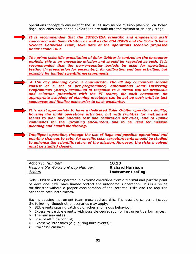
operations concept to ensure that the issues such as pre-mission planning, on–board flags, non-encounter period exploitation are built into the mission at an early stage. It is recommended that the ESTEC/ESA scientific and engineering staff concerned with Solar Orbiter, as well as the ESA SSWG and the Solar Orbiter Science Definition Team, take note of the operations scenario proposed under action 10.9. The prime scientific exploitation of Solar Orbiter is centred on the encounter periods; this is an encounter mission and should be regarded as such. It is recommended that the non-encounter periods be used for operations testing (in preparation for encounter), for calibration and test activities, but possibly for limited scientific measurements. A 150 day planning cycle is appropriate. The 30 day encounters should consist of a set of pre-programmed, autonomous Joint Observing Programmes (JOPs), scheduled in response to a formal call for proposals and selection procedure with the PI teams, for each encounter. An appropriate schedule of planning meetings can be set up each orbit to test sequences and finalise plans prior to each encounter. It is most appropriate to have a dedicated Solar Orbiter operations facility, housing the flight operations activities, but with facilities for instrument teams to plan and operate test and calibration activities, and to uplink commands for the upcoming encounters, and to be used for mission planning and health monitoring. Intelligent operation, through the use of flags and possible operational and pointing changes to cater for specific solar targets/events should be studied to enhance the scientific return of the mission. However, the risks involved must be studied closely. Action ID Number: 10.10 Responsible Working Group Member: Richard Harrison Action: Instrument safing Solar Orbiter will be operated in extreme conditions from a thermal and particle point of view, and it will have limited contact and autonomous operation. This is a recipe for disaster without a proper consideration of the potential risks and the required actions to safe instruments. Each proposing instrument team must address this. The possible concerns include the following, though other scenarios may apply: SEU events causing Latch up or other anomalous behaviour; Excessive particle events, with possible degradation of instrument performances; Thermal anomalies; Loss of attitude control; Excessive intensities (e.g. during flare events); Processor crashes;
92

Etc… The instrument teams must demonstrate that for the particular events, which may upset or damage their instrument, there is an onboard process for (a) identifying the problem, and (b) taking evasive action. For example, the following cases may apply: Event Action Particle Event If excessive particle numbers are registered, i.e. above a
specified threshold, either as extracted 'cosmic ray' flux recorded from images, or as an intensity registered by one of the particle instruments, some instruments may wish to close doors and/or reconfigure into a safe 'sleep' mode. This must be automatic. Due to the lack of contact, it would be useful to be able to monitor any particle fluxes from the in situ instruments and include the ability to switch on again, in observation mode as the particle event subsides.
SEU Each instrument must be able to recognise latch up and have built in autonomy to enable a reset and switch on to avoid the loss of encounters. See action 10.8. Also, each instrument must monitor for anomalous events, and reset if necessary.
Thermal Anomalies The thermal control will be complex and for each instrument may rely on passive radiators, heat switches, shields, thermal blankets, heat stops, reflection, heaters etc… The thermal control must be somewhat autonomous and this must be built into the instrument plans. The instruments must be able to regulate themselves. However, there may be anomalies, and these will require the definition of thresholds above which the instrument will shut down into a safe mode - which is to be defined. A thermal reconfiguration of an instrument to be triggered by the spacecraft must be possible in case of instrument failure to go into safe mode.
Loss of Attitude Control
Each instrument must have a safe mode - most likely with doors shut and heaters set at a nominal level. If attitude control is lost, each instrument must adopt this mode, though the signal to inform each instrument of the loss of control must come from one source, e.g. the spacecraft, or VIM - this is TBD.
Excessive Intensities
This is included as an example of an event, which influences a single instrument. The variability of the solar radiance in the UV/EUV is generally larger than the dynamic range of any existing detector. If, for example a flare occurs, the instrument must be able to recognise the dynamic event and respond to it in a way to avoid over-exposure and guarantee useful data. Such events must be defined for each instrument at the time of the proposal.
Processor Crashes All instruments have computer crashes at times and rather than wait for the ground operations to identify the crash, which may be after an entire encounter, it would be sensible to consider ways of rebooting instruments automatically.
93

We have identified for illustration just a few possible event types, such as SEUs, particle events, thermal anomalies etc…, which could require evasive action by the instruments. They illustrate that (a) we must build in schemes for recognising problems, and (b) we must be able to respond to them - all without ground contract. It stresses that each instrument team must define a basic 'safe mode' and must list possible dangerous events and suggested responses at the time of proposal. Note that some of these activities suggest options where information is exchanged between instruments. Action ID Number: 11.1 Responsible Working Group Member: A. Gabriel Action: Refinement of the Solar Orbiter Science Objectives Note from R. Harrison: Solar Orbiter was 'sold' on four new aspects of solar research - i.e. close encounter observations, inner heliosphere measurement, high latitude observations of the Sun, and co-rotation with the Sun during perihelion. Although these new and unique aspects for solar observation are compelling reasons for flying Orbiter, they are not, in themselves scientific objectives. Thus, although the Solar Orbiter proposal discussed a range of scientific investigations and targets, there is no formal definition of the scientific goals for Solar Orbiter. Focusing the Solar Orbiter goals is a task for the Solar Orbiter Science Definition Team (SDT). However, there are aspects of this that do influence instrument designs - e.g. wavelength selection, resolution, fields of view. Thus, some discussion was raised at the PWG meetings. It was decided that one way to tackle this question was for the PWG members to co-ordinate some thinking about the use of Solar Orbiter in preparation for the SDT. This is being done through Alan Gabriel, who has received input from the PWG members and will be producing a separate report, which will be tabled at the SDT meetings. One input to that discussion was a document prepared just after the 2001 Tenerife Solar Orbiter Workshop, by R. Harrison, which attempted to lay down some basic foundations for the Solar Orbiter goals. This is included as Appendix 3. The Solar Orbiter Science Definition Team, as well as the ESA SSD and SSWG, are invited to take note of the PWG study on Solar Orbiter science goals, to be produced by Alan Gabriel. The Challenges: Requests for ESA Support The actions have highlighted two areas where it was felt that ESA support was required, mainly because of the multi-instrument nature of the issue in question in each case. These are items 1.6 and 10.3 in the action list and are concerned with the integrity of optical surfaces/components in the environment to be encountered by Orbiter, and the development of suitable detector systems. These are the subjects of the more complete, stand-alone reports of Appendix 1 and 2, as well as recommendations made in the relevant parts of the last section. It is recommended that ESA take a role in ensuring that these activities are achieved in good time.
94
The two reports were submitted to ESTEC/ESA for consideration in January 2003. The Payload Definition Documents (PDDs) The second principal activity of the PWG was the production of the PDDs for EUI, EUS, UVC, VIM and RAD. This activity has been performed in parallel with the actions discussed above. The PDDs form the instrumental input to the industrial studies and they are seen as living documents, updated through discussion between Thierry Appourchoux and the PWG members. Since they are a product of the PWG activities, the PDDs for the five remote sensing instruments are attached in Appendix 4. Final Words The PWG activity has been rather successful in identifying areas of concern, or challenges, and in assessing the feasibility of overcoming these, as well as in defining the nature of the instruments which would be flown on Solar Orbiter. Thus, this report is submitted as a rather complete summary of the principal work of the remote sensing PWG. We hope that it serves as a reference to help define and refine the mission and instruments, and as a study to provide confidence in the feasibility of a mission scenario being adopted for Solar Orbiter. Other documents, notes etc… can be found at the Web site.
95

APPENDIX 1: Solar Orbiter Payload Working Group Remote Sensing
Solar Orbiter Working Group Action 1.6: Integrity of optical components, filters, multilayers:
Required tests on optical components
Udo Schühle, Max-Planck-Institut für Aeronomie
Luca Poletto, Istituto Nazionale per la Fisica della Materia (INFM)
Clarence Korendyke, Naval Reasearch Laboratory
January, 2003
96

I. INTRODUCTION The remote-sensing instrumentation of Solar Orbiter will be subject to severe environmental conditions, due to the close approach to the Sun and the high eccentricity of the orbit, from 0.2 AU to 1 AU. Optical components, such as filters and mirrors, are affected not only by the variable thermal radiation, but also the flux of solar particles. Tests are required to validate their robustness against the radiation environment and to verify the effects of degradation in time. We consider several possible ways in which the variable environmental conditions degrade the performance of these optical systems in orbit:
1. variable heat input, changing between 1.3 and 34 kW/m2. 2. variable particle flux of the slow solar wind, changing between 4x10¹² to
1x10¹⁴ protons/m2 3. variable flux of high energy particles (>0.1 MeV) from solar activity during
the mission time 4. variable flux of the UV radiation in combination with organic material, leading
to polymerization on optical surfaces. For each instrument of the strawman payload the optical surfaces must survive these conditions with degradation within acceptable limits. Below, we first discuss these four different radiation effects in general and then outline the tests needed for the optical elements of each single instrument of the strawman payload. 1. Heat input The variable heat input to the payload instruments must be dissipated by regulated heat conduction to radiators. Technical solutions for this must be studied in general. Despite a regulated dissipation, some optical surfaces will reach very high temperatures during the journey close to the Sun. First thermal models of the payload instruments predict very high temperatures for the primary optical surfaces (mirror coatings, multilayers, filters). These optical components must be tested under irradiation of 25 solar constants to show their integrity under these conditions. 2. particle flux of the slow solar wind The average flux of solar wind particles of the quiet Sun at 1 AU is fairly constant. It consists mainly of 4x10⁸ protons/cm2/s, 2x10⁷ He++/cm2/s at an energy of typically 1 keV. Within the variable distance from the Sun during the orbit, this flux will change according to 1/R2. Thus, for a safe estimation of the total dose we can assume that the flux is on the average an order of magnitude higher. For a mission time of 2500 days we arrive at a total dose of solar wind protons of 8x10¹⁷/cm2 plus 4x10¹⁶/cm2 of He++ (Alpha particles). The optical surfaces directly exposed to this particle flux will undergo chemical changes within the first atomic layers, where the low energy protons (and Alphas) are stopped. The stopping power of Alpha particles is about one order of magnitude higher than for protons, which approximately compensates their lower abundance. We are thus facing an equivalent dose of 1.6x10¹⁸ protons/cm2 at 1 keV. Optical surfaces exposed to the solar wind should be subjected to a test which measures the performance degradation during such an exposure. Since this radiation can be easily shielded by the metal housing of the instruments, only the first optical surface of an instrument is concerned. In addition, the first optical surface can be
97
protected against this exposure if electrostatic deflection plates can be placed far enough ahead of the surface to deflect the solar wind. Surfaces with dielectric (, non-conductive) coatings may be damaged due to charge formation and possible discharge with pit formation (see Fuqua, 2002), if they are exposed to the solar wind. As a test for the SOHO mission, samples of SiC mirrors of the SUMER instrument have been tested to a level of 3x10¹⁶ per cm2 of H+/H2+ and He+ ions in an experiment. The irradiation resulted in amorphisation and erosion of the mirror surface and corresponding reduction of reflectivity (see SUMER Contamination Study, 1989). For this reason electrostatic deflecting plates were implemented inside the SUMER telescope to protect the primary mirror. 3. solar energetic particles (SEPs) Major flux of energetic particles is to be expected only during solar energetic events (flares, CMEs). A first-order estimation of the energetic radiation has been given by the In-Situ Payload WG based on the study made for Solar Probe and published by Tsurutani at al. (2000). It is assumed that the flux of particles during major flares goes with 1/r2 with the distance from the Sun. According to the tables given by the In-Situ PWG we expect a maximum flux at perihelion of 106 protons and He-ions/cm2/s at energies >10 MeV during an event. The estimation for the fluence per event is 109/cm2. Only few such events can occur during the short period of perihelion passage and only several can be expected during the solar cycle. Nevertheless, it should be kept in mind that the high flux of a possible event during perihelion passage may temporarily saturate a detector. The total fluence to be expected during the mission may have an effect on optical filters due to dislocation damage from the heavy ions. However, tests performed on filters of previous missions show very small effects: A corresponding study has been made for SOHO at a fluence of 6x10¹¹ protons /cm2. A loss of transmission of few percent of the optical filters was measured as a result of the irradiation (Appourchaux, 1993). The same dose was applied to SiC mirror samples for the SUMER instrument with no change in their reflectivity. Similar tests were performed on the interference filters for the WAC camera on Rosetta, showing essentially no degradation in time (Naletto et al., 2003) at a fluence of 1.5x10¹¹ protons/cm2 at 4 MeV. CCD detectors are more vulnerable to radiation damage. A survey of radiation damage to CCD devices has been performed for the OSIRIS cameras on Rosetta (Sierks 2001). At a fluence greater than 108/cm2, effects on the charge transfer efficiency and the dark current have been reported. 4. UV irradiation and organic contamination The organic material, needed to build an instrument, generally leads to outgassing molecules which are able to deposit on any surfaces. The residence time on that surface depends on its temperature. Thus a condensation on an optical surface can be largely reduced by keeping it at a high temperature. If, however, at the same time the surface is exposed to UV radiation, the condensed material can be activated and polymerized, resulting in irreversible deposition on the surface. In this process,
98

the rate of deposition depends on the arrival rate of molecules at the surface, the desorption rate from the surface (given by its temperature), and the UV flux. The solar UV flux is well known, so the measurement of molecular deposition under solar irradiation can in principle be measured easily (using a quartz crystal microbalance (QCM)) in a vacuum test set-up. It is essential in this experimental set-up to simulate the solar UV spectrum, while a surface (the QCM) is exposed to a certain outgassing organic source. For the SOHO mission, preliminary measurements of this kind have been performed (SUMER, 1989, Schühle, 1993) for the UV irradiance at 1 AU. But for Solar Orbiter the irradiance will be variable during the orbit with very high flux at perihelion (25 times higher than at 1 AU). This makes it unavoidable that certain surfaces of the instruments will change their temperatures during the orbit, leading to offgassing of previously condensed material (see Schühle, 2002). In addition, at the higher irradiance the polymerization and deposition rate may be higher. It has never been measured, how much the deposition of contaminants will be accelerated at this irradiance level. For a careful estimation of the contamination risk of exposed optical surfaces it is thus necessary to carry out such a contamination simulation test with a UV irradiance that is expected during the Solar Orbiter mission orbit. For instruments of the Solar Orbiter payload that are not operating in the UV, it is only the first optical filter blocking the UV which will be under risk. In general, degradation at a mirror surface is twice as high as compared to transmission optics, because the light has to pass twice through the contamination layer. For a UV instrument it is the mirror with the highest UV flux density. This makes grazing incidence mirrors less vulnerable in two ways: First, the density of UV flux (per mirror area) is lower than at normal incidence mirrors and, second, the UV reflectance is not so much affected by the deposited material, because at grazing incidence the reflectance of materials is generally higher than at normal incidence. II. IDENTIFICATION OF SENSITIVE PAYLOAD ITEMS Critical items of the payload optical instruments are generally the first optical surfaces of the instruments, which cannot be protected against the radiation and/or heat input. We can identify the most critical optical components in the present strawman payload: 1. Interference filters for the visible (VIM) 2. Thin filters for the EUV (EUI) 3. Mirrors for the visible (UVC) 4. Mirrors for the EUV (EUS) The effects of the radiation environment mentioned above have to be evaluated either by literature search or by tests as specified below. III. TESTS REQUIRED FOR EACH INSTRUMENT We can list the main tests required to validate the use of such components as the first optical element of an instrument looking at the solar disk. 1. Interference filters for the visible
The interference filters for VIM are supported on a quartz substrate. This gives the required stiffness and assures a good thermal transmission for power
99

dissipation. Generally, dielectric multilayer filter coatings are sustainable to high temperatures. Thermal environment: A detailed thermal analysis is required in order to check the stability at the operating temperature at 0.2 AU (34 kW/m2) and to assess the stability during the orbital variations (from 34 kW/m2 to 1.3 kW/m2). A thermal balance test must be conducted with a prototype design of the filter, simulating the orbital radiation conditions. Filter transmission and absorption properties must be measured before and after (-better during-) the test. Radiation and particle environment: The quartz substrate of the entrance filter is stable in the radiation environment, and if the multilayer interference coating is on the back side of the quartz substrate, then it is well protected against the solar wind particles. Depending on the thickness of the window, the high energy component of the SEPs may have only a negligible effect on the filter transmission. However, the radiation tolerance of liquid crystal modulators must be evaluated. In addition, a solid crystal etalon (LiNbO3) may degrade under SEP radiation even under very low fluence, due to the high field strength (of several 10KV/cm) across the crystal substrate. It is recommended to perform a verification of the electrical integrity after irradiation.
2. Thin filters for the EUV A thin Al filter is the first optical element of the EUV imager. A long baffle reduces the thermal load on the filter to few solar constants. Thermal environment: A feasibility study is required in order to check the stability at 0.2 AU. Thermal tests could be required, depending on the results of the thermal analysis. Radiation and particle environment: These filters have already space heritage. No tests are required. However, a single filter may pose the risk of a single point failure. Thus a double filter may be a safer solution.
3. Mirrors for the visible The UVC design has a normal-incidence mirror that rejects the visible light coming from the disk out of the coronagraph. At 0.2 AU, the mirror receives a thermal power of 34 kW/m2. Thermal environment: Under high UV irradiation, any contaminant deposited on an optical surface polymerizes, so the reflectivity of the surface decreases. Under the extreme irradiation conditions at 0.2 AU, there is a risk of a degradation of the reflectivity and a consequent increase of the thermal absorption. The effect has to be quantified, since it is very important for the radiator design. Thermal tests are required. The mirror has to be exposed to a controlled environment and illuminated with an intense visible and UV flux (e.g. the radiation coming from an intense Hg-Xe lamp and concentrated in a small spot). Radiation and particle environment: The visible reflectivity should be not drastically affected by the radiation and particle environment. No tests are required.
4. Mirrors for the EUV: conventional optics The first optical component of the spectrograph is a telescope mirror producing an image of the Sun on the spectrograph entrance slit. Thermal environment: The degradation of the EUV reflectivity due to the polymerization is extremely critical for the spectrograph, since it could drastically reduce the efficiency of the spectrograph.
100

Thermal tests are extremely important for the design of the spectrograph. The mirrors have to be exposed to a contamination environment and illuminated with an intense flux from a UV source. The degradation of the EUV reflectivity has to be measured as function of time and partial pressure of the contaminants. The tests have to be performed both in normal and in grazing incidence, using gold-coated optics in normal incidence and Si-coated optics in grazing incidence. Radiation and particle environment: Tests on damages from particles have been performed for the SiC mirrors of SUMER. The primary mirror must be protected from the solar wind flux. The SEP fluence does not pose a concern for mirrors with thick coating.
5. Mirrors for the EUV: multilayer optics A multilayer mirror could be used in the telescope of the spectrograph, depending on the spectral region of operation and in the EUV imager. However, in the EUV imager they are protected by the entrance filter. Thermal environment: Thermal tests are extremely important for the design of the spectrograph and the EUV imager. The degradation of the EUV reflectivity due to polymerization has to be quantified. Radiation and particle environment: For the unshielded multilayer optical components – primary mirror of the spectrograph -, tests are required in the radiation and particle environment expected at 0.2 AU. If a solar wind deflector is impractical in this optical design, it must be tested if the multilayer optics are affected by the high fluence of low energy protons and alpha particles.
In summary: 1. A detailed document on the expected radiation and particle environment at 0.2
AU is needed. 2. A document on the thermal analysis of the interference filter for VIM is needed.
Tests of radiation hardness of liquid crystal modulators and LiNbO3-crystals are recommended.
3. A document on the thermal analysis of the filters for EUI is needed. 4. We recommend tests for optics degradation due to contaminant condensation
and polymerization (conventional optics at normal and grazing incidence, multilayer mirrors) at different solar UV irradiances between one and 25 solar constants.
5. We recommend tests of degradation of multilayer optics due to particle radiation of the solar wind corresponding to 1 and 0.2 AU.
IV. FURTHER TESTS RECOMMENDED FOR SOLAR ORBITER The contamination working group recommends that ESA establish a test programme for all optical and thermal components on the solar orbiter. The test programme should concentrate particularly on components directly illuminated by solar radiation. It would cover the issues related above. The proposed components should be well characterized before and after testing. The particle related testing should be conducted using standard techniques to simulate the exposure to the solar wind and the solar energetic particles. The heat, solar irradiation and contamination studies are necessarily coupled and require a more sophisticated approach. The high temperatures are directly caused by the exposure to multiple solar constants. Depending on the thermal geometry, complex gradients may be present within the various components. The dwell time of the contaminants sticking to the surfaces is directly related to the surface temperature. The effective rate of photodeposition will increase with increasing solar
101

irradiance. This must be investigated quantitatively. The rate of UV photodeposition will also vary with chemical composition of the contaminant and the spectrum of the UV exposure. These mechanisms of UV photodeposition are not well enough understood to make reliable predictions for the Solar Orbiter mission. Based on the previous experience of the committee members, we would suggest that the component tests be conducted in a dedicated, well understood chamber using measurement techniques similar to those used in the ASTM 1559 standard testing. The sample should be placed in a fluence cell with various ports leading to TQCMs and also a sample cell containing a candidate contaminant material. Multiple TQCMs at various temperatures will be required to obtain some measure of the constituent activation energies. The temperature of the contamination sample should have a reasonable degree of adjustment. The component sample must be capable of being heated in a sustainable manner to very hot temperatures. Additionally, a UV/visible solar simulator source capable of 25 solar constants must illuminate a reasonable patch (~1 cm) or so of the surface. This could be created by optically concentrating the effective output of a 5 cm solar simulator into a smaller diameter. A reasonable size of component with a 5 cm diameter optical area could be readily used for much of this testing. The detailed definition of this test geometry is clearly a significant task and not within the charter of this working group. The working group additionally feels that these issues raised herein may very directly influence the solar orbiter instrument and spacecraft designs. Thus, early testing would be very beneficial to the program. References: SUMER Contamination Study, SUM-MPAE-SS-02000-00-00, (1989) P.D. Fuqua, N. Presser, J. D. Barrie, M. J. Meshishnek, D. J. Coleman, Appl. Opt. 41, 3142-3149, (2002) U. Schühle, "The cleanliness control program for the SUMER/SOHO experiment", in: UV and X-Ray Spectroscopy of Astrophysical and Laboratory Plasmas, E.H. Silver and S.M. Kahn, (Eds.), Cambridge University Press, 373-382, (1993) Tsurutani,et al., (2000), http://outerplanets.larc.nasa.gov/outerplanets/Radiation_Environ2.pdf Appourchaux T. P., "Effect of space radiations on optical filters", Proc. SPIE 2018, 80 - 91 (1993) U. Schühle, R. Thomas, J.-F. Hochedez, "The Solar Orbiter Mission and Design Recommendations", in The Radiometric Calibration of SOHO, ISSI Scientific Report SR-002, 361 - 370, ESA Publications Division, Noordwijk, (2002) G. Naletto, A. Boscolo, J.Wyss, A. Quaranta, “Effect of proton irradiation on glas filter substrates for the Rosetta mission”, Applied Optics, submitted, (2003)
102
APPENDIX 2: Solar Orbiter Payload Working Group Remote Sensing
Detector Development Requirements for the ESA Solar Orbiter
Remote Sensing Instruments
Richard A. Harrison, Rutherford Appleton Laboratory
Jean-François Hochedez, Royal Observatory of Belgium
January 10, 2003 Updated: March 12, 2003
103
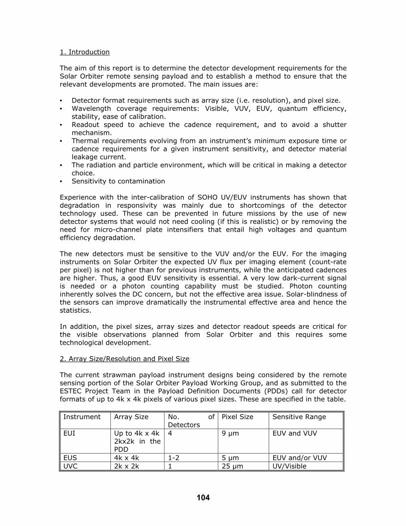
1. Introduction The aim of this report is to determine the detector development requirements for the Solar Orbiter remote sensing payload and to establish a method to ensure that the relevant developments are promoted. The main issues are: • Detector format requirements such as array size (i.e. resolution), and pixel size. • Wavelength coverage requirements: Visible, VUV, EUV, quantum efficiency,
stability, ease of calibration. • Readout speed to achieve the cadence requirement, and to avoid a shutter
mechanism. • Thermal requirements evolving from an instrument’s minimum exposure time or
cadence requirements for a given instrument sensitivity, and detector material leakage current.
• The radiation and particle environment, which will be critical in making a detector choice.
• Sensitivity to contamination Experience with the inter-calibration of SOHO UV/EUV instruments has shown that degradation in responsivity was mainly due to shortcomings of the detector technology used. These can be prevented in future missions by the use of new detector systems that would not need cooling (if this is realistic) or by removing the need for micro-channel plate intensifiers that entail high voltages and quantum efficiency degradation. The new detectors must be sensitive to the VUV and/or the EUV. For the imaging instruments on Solar Orbiter the expected UV flux per imaging element (count-rate per pixel) is not higher than for previous instruments, while the anticipated cadences are higher. Thus, a good EUV sensitivity is essential. A very low dark-current signal is needed or a photon counting capability must be studied. Photon counting inherently solves the DC concern, but not the effective area issue. Solar-blindness of the sensors can improve dramatically the instrumental effective area and hence the statistics. In addition, the pixel sizes, array sizes and detector readout speeds are critical for the visible observations planned from Solar Orbiter and this requires some technological development. 2. Array Size/Resolution and Pixel Size The current strawman payload instrument designs being considered by the remote sensing portion of the Solar Orbiter Payload Working Group, and as submitted to the ESTEC Project Team in the Payload Definition Documents (PDDs) call for detector formats of up to 4k x 4k pixels of various pixel sizes. These are specified in the table. Instrument Array Size No. of
Detectors Pixel Size Sensitive Range
EUI Up to 4k x 4k 2kx2k in the PDD
4 9 µm EUV and VUV
EUS 4k x 4k 1-2 5 µm EUV and/or VUV UVC 2k x 2k 1 25 µm UV/Visible
104

VIM 2k x 2k 1 10 µm Visible HI 2k x 2k 1 TBC Visible STIX See below 2 TBC X-ray and visible
Pixel size will have a direct bearing on the size and mass of the remote sensing instruments through their optical designs. Small pixels lead to shorter and thus smaller camera optics, but they generally come with smaller signal to noise ratio (SNR), and sensitivity. Some compromises between resolution and pixel size may be inevitable. The above table does not include the in-situ strawman instruments. Also not included is the RAD instrument, which would use an active cavity detector. Two further remote sensing options are being considered, which are not part of the core strawman payload, namely a visible light Heliospheric Imager (HI), which would use a 2k x 2k APS front-illuminated detector, and a High Energy Imager (STIX), which would use CdZnTl detectors to detect 3-150 keV X-rays, but would also use an APS visible light detector for aspect measurement. These are included in the Table. 3. Wavelength Coverage Current strawman payload instruments work from the EUV through to the visible as shown above. Detector materials and technology will be critical, and must be tailored to the waveband of interest; i.e. the sensors will have to be optimised differently depending on the wavelength range of interest. It would be useful to assess as soon as possible the need to have imagers in the more difficult VUV range (e.g. Lyman-alpha). 4. Thermal Requirements Detector SNR requirements and hence, cooling requirements will depend on an instrument’s exposure timing, sensitivity requirements, and the detector’s inherent readout noise and thermal leakage current. The detector’s leakage current will depend on the leakage within the detector material itself, and in the silicon readout circuit (ROIC) in the case of hybrid detectors. Each instrument will need to trade overall sensitivity against detector readout noise, and the leakage current accumulated between readouts. 5. The Radiation / Particle Environment We may anticipate a solar wind ‘background’ proton flux some 25 times greater than that of SOHO (assuming 1/r2). For an average flux at 1 AU, of density 9 cm-3 (average speed and temperature of 300 km/s and 4 x 10⁵ K (3.5 keV)) we expect 225 cm-3 at 0.2 AU. Thus the nominal particle environment will be similar to some modest storm events detected by SOHO, which have proven to be quite disruptive to some observations. There may also be an increased chance of encountering proton ‘storms’, due to vicinity, from shocks associated with mass ejection, with up to thousands of proton hits per second. One might expect events similar to those experienced by SOHO, with greater intensity, and, in addition, some near-Sun events may be generated by lateral expansion of CME disturbances (e.g. consider the coronal ‘EIT’ waves). The exact intensities remain unknown. The geometrical factors and magnetic
105

configurations, which may play a role in defining the chance of occurrence are also largely unknown. Also, we anticipate occasional impacts from solar flare neutrons whose 15.5 minute lifetime means that most missions do not encounter them. Finally, we anticipate a similar cosmic ray (non solar) flux to that at SOHO. The net effect is an increase in particle hits, with some extreme conditions including occasional neutrons. 6. Detector Options 6.1 CCDs The most significant concerns with current science-grade CCD technology are: • Radiation damage. • Minimum pixel size – probably 10 microns. • Array format – 4kx4k pixel sensors still in development (e.g. 4k x 4k CCD
detector is being planned for NASA's SDO). The particle environment, which will be encountered by Solar Orbiter means that CCD-type detectors will most likely be inappropriate. The radiation damage in CCDs is mostly caused by the creation of charge traps reducing the charge transfer efficiency (CTE) (Ref. 1). The current optical design of the EUS instrument requires a detector pixel size of ~ 5 microns for a realistic accommodation of the instrument on the spacecraft and this appears to be beyond the capabilities of a CCD option. 6.2 Active Pixel Sensors (APS) Monolithic silicon Active Pixel Sensors (APS) are a more realistic option for Solar Orbiter because they promise: • Much Greater radiation tolerance than CCDs. • Smaller pixel size (Ref. 2). • Integration of on-chip readout electronics (e.g. RAL have already developed a 1
MHz 16 bit ADC in 0.35 µm technology and have transferred the design to 0.25µm for integration on a 4kx4k APS - Ref. 3).
• Fast read-outs The radiation hardness of silicon APS detectors is much higher than for CCDs because the CCD’s CTE degradation is not applicable (ref. 2). There is no large-scale charge transfer; each pixel’s charge is sensed and buffered within the pixel. Charge collections efficiency may degrade, but there are good reasons to believe the effect will be at higher radiation levels than in CCDs. Some investigative work is required. Compared to current science-grade CCDs, CMOS APS pixels can be made very much smaller enabling shorter camera optics systems, and leading to very much smaller and lighter instruments.
106

In contrast to CCD technology, the readout electronics for CMOS APS detectors can be incorporated on-chip leading to large savings in readout electronics size, mass, and power (Ref. 2). The most significant question for APS technology is wavelength coverage. The imaging and spectroscopy requirements for Solar Orbiter (EUI, EUV, UVC, VIM as well as HI and STIX) call for large arrays and small pixels. Although there are several companies, world-wide, producing APS detectors, almost all are aimed at the commercial markets. A 4k x 4k APS 5 micron array has been fabricated in the USA but not with science-grade performance or EUV/UV sensitivity in mind. 6.2.1 Front illuminated APS detectors For the visible detectors for VIM and UVC (also HI and STIX), front illuminated APS devices could be used. Detectors of applicable format and pixel size may be expected within the next 12 months. 6.2.2 Back-thinned APS detectors Recognising the importance of APS technology for future space flight instrumentation, the Rutherford Appleton Laboratory (RAL) has initiated a research programme to develop large format science-grade arrays with small pixel sizes. Also recognizing the requirement for EUV/UV sensitivity for Orbiter, and other missions, a collaboration has been set up between RAL and E2V (Marconi) in the UK with the aim of developing the technology necessary for successful thinning and back-illumination of CMOS sensors. The back-thinning of CCDs is a well established technique at E2V, and has been used for numerous space applications. This technology is now being applied to the APS. The aims of the work co-ordinated through RAL, with emphasis on APS detectors and on Solar Orbiter in particular, are given at http://www.orbiter.rl.ac.uk/solarorb/rspwg/actions/raldetectors.ppt. Development work so far is summarised by the following: (I) a front-illuminated APS with 512x512 pixels (Ref. 2) has been produced, samples of which have been thinned by E2V and delivered recently (December 5, 2002) - the thinning work receives no direct funding and so progress to date has been on a ‘best efforts basis'; (ii) a new 4k x 3k APS with 5 micron pixels, and specifically designed with back-thinning in mind has recently been delivered to RAL for testing. The aim of the programme is to provide EUV/UV sensitivity, for a large array with small pixels, and with good radiation tolerance. We anticipate that a 4kx4k 5-micron EUV/UV sensitive APS detector could well be readily available within 2 years given appropriate support. 6.3 The Bold Detectors A consortium (the BOLD consortium) has been set up with the goal to develop new APS-type UV detectors with wide-band gap materials (e.g. Diamond and Nitride materials). The basic goals of these devices are:
107

• They are blind in the visible and near infrared, thus increasing the overall effective area in the VUV and EUV;
• Are designed to be directly sensitive to the EUV/UV, removing the need for microchannel plates (MCPs);
• Are rad-hard to SEPs (Solar Energetic Particles) and UV radiation. • Benefit from all APS-specific gains However, the approach does require the bump-bonding of a detector material on top of the ROIC. The development of a prototype detector system is being supported by ESA (ref. 5). A full characterization including the responsivity measurement from the near-UV to soft X-rays, will be performed on the first prototypes during 2003. Further, such measurements will be undertaken, as necessary, at the LGEP (Near UV), the LPL (VUV), and the Berlin electron storage ring BESSY II by Physikalisch-Technische Bundesanstalt (PTB) in collaboration with the Max Planck Institut fur Aeronomie. The wavelength range is between 0.7 and 400 nm. The final characterisation will also include stability measurements under EUV radiation. A non-imaging prototype will fly aboard the LYRA instrument of the ESA Proba-2 micro-mission in 2004. This will measure solar irradiance in four EUV/UV channels. The Web site for the BOLD consortium is at http://bold.oma.be/. It is co-ordinated through the Royal Observatory of Belgium, by Jean-Francois Hochedez, and includes the Max-Planck Institut fur Aeronomie, Lindau, Germany; the Institut d’Astrophysique Spatiale, Orsay, France; the XUV Laboratory of the University of Florence, Italy; the Universidad Politecnica de Madrid, Spain; Laboratoire d’Etudes des Proprietes Electroniques des Solides, France; Laboratoire de Genie Electrique de Paris, France; Laboratoire de Physique des Lasers, Universite Paris 13, France; Laboratoire pour ‘Utilisation du Rayonnement Electromagnetique, France; Centre de Recherche sur l’Hetero-Epitaxie et ses Applications, France; Instituut voor Materiaal Onderzoek, Belgium; and IMEC, Belgium. Other references for BOLD development work are given in Refs. 6 onwards. 6.4 C3Po Detectors The Charge Caching CMOS detector for Polarimetry, known as C3Po detector, is a strong candidate for the VIM instrument. The basic idea of the detector is similar to the BOLD detector, with current applications using Si for the wavelength range 200-1100 nm and HgCdTe for 1000 to over 10,000 nm, instead of diamond. The fundamental difference is in the design of the pixels, which include a more complex transistor design to allow the storage of several images. This can be used to extract rapid image differencing such as in polarimetry measurements, or for Doppler measurements. The basic description of these detectors can be found at http://www.noao.edu/noao/staff/keller/c3po/c3po.html (refs. 11, 12). 7. PDD Choices The overall detector requirements for Solar Orbiter, accounting for the radiation/particle environment, combined with the need to produce small, low mass, high resolution instruments (i.e. small pixels with large arrays) has led to the choice of detector arrays, pixel sizes and types as shown below for the UV/EUV and visible imaging and spectroscopic instruments.
108

Instrument Array Size Pixel Size
Sensitive Range
Detector Type
EUI Up to 4k x 4k 9 µm EUV BOLD or APS back-thinned EUS 4k x 4k 5 µm EUV APS back-thinned baseline,
with BOLD as alternative. UVC 2k x 2k 25 µm UV/Visible APS back-thinned with MCP
and front illuminated APS VIM 2k x 2k 10 µm Visible C3Po detector with front
illuminated APS as alternative.
In addition, the HI and STIX instruments refer to front-illuminated APS detectors. 8. Conclusions It is clear that the remote sensing instruments on Solar Orbiter require the completion of some development work, both in the APS and wide band-gap technologies, if we are to make the mission deadlines, and that it would be prudent to liaise with the relevant groups to ensure that the requirements for Orbiter are catered for. To ensure this, it would be wise to provide some support for the relevant development work. Specifically, the development of the back-thinned APS detectors, the BOLD solar-blind detectors and the C3Po detectors are critical to Solar Orbiter. Thus, it is recommended that there be a project-wide approach to ensuring that Solar Orbiter’s needs are catered for in a timely manner in the detector development programmes. The following is a suggested programme of work, to be partly supported by ESA: 1. Set up a liaison mechanism with the detector groups to discuss and oversee the
requirements for Solar Orbiter. This could be in the form of an ESTEC contact attending occasional review meetings and providing Orbiter requirement information. This must include the provision of Solar Orbiter specifications and requirements on the one hand (array sizes, pixel sizes, sensitivity ranges and values etc…), and a consideration of detector and technology specifications and requirements on the other. This could involve the Solar Orbiter Payload Working Group or the Solar Orbiter Science Definition Group, as appropriate.
2. Establish key milestones for development of Orbiter-required technology, e.g. prototype development dates and model specifications, and test activities.
3. Provide support for the development of a 4kx4k, 5 micron EUV sensitive back-thinned APS array, including test activities, to be ready during 2003. In particular, provide support for further work on the design and fabrication of optimal 5 micron pixel test structures, the thinning work at E2V (currently unfunded and progressing on a ‘best efforts basis’), and a more comprehensive test programme.
4. Provide support for the development of a large format small pixel size BOLD demonstration prototype, including test activities, targeted for completion before the 2004 Solar Orbiter A.O.
5. Provide support for the development of a large format C3Po prototype for Solar Orbiter, targeted for completion before the 2004 Solar Orbiter A.O.
References:
109

(1) M. Clampin, “Ultraviolet-optical charge-coupled devices for space instrumentation”, Opt. Eng. 41 (6), 1185-1191, 2002. (2) N.R. Waltham, M. French, M. Prydderch, Q. Morrissey, R. Turchetta, A. Marshall, J. King, and G. Woodhouse, (2002), CMOS Active Pixel Sensor developments at the Rutherford Appleton Laboratory, Proceedings of the Workshop on Scientific Detectors for Astronomy, June, 2002, Hawaii, in press (3) N.R. Waltham, M.J. French, L.L. Jones and G.F.W. Woodhouse, (2002) “The use of ASIC technology in the development of compact, low-power CCD cameras” Proceedings of the Workshop on Scientific Detectors for Astronomy, June, 2002, Hawaii. In Press. (4) J. Janesick, “Dueling Detectors”, Opt. Eng. 41, February 2002. (5) J.-F. Hochedez et al., “Blind to optical light detectors – A European investigation for UV sensing on-board the Solar Orbiter”, Proposal submitted to ESA, July 2002. (6) J.-F. Hochedez, E. Verwichte, P. Bergonzo,B. Guizard, C. Mer, D. Tromson, M. Sacchi, P. Dhez, O. Hainaut, P. Lemaire, P., J.-C. Vial, “Future diamond UV imagers for solar physics”, Physica Status Solidi Applied Research (a) 181, 141-149, 2000. (7) J.-F. Hochedez, P. Lemaire, E. Pace, U. Schühle, and E. Verwichte, E., “Wide bandgap EUV and VUV imagers for the Solar Orbiter”, SP-493, in proceedings of Solar Encounter, The First Solar Orbiter Workshop, Puerto de la Cruz, Tenerife, Spain, 14-18 May 2001, 245-250, 2001. (8) J.-F. Hochedez, P. Bergonzo, M.-C. Castex, P. Dhez, O. Hainaut, M. Sacchi, J. Alvarez, H. Boyer, A. Deneuville, P. Gibart, B. Guizard, J.-P. Kleider, P. Lemaire, C. Mer, E. Monroy, E. Muñoz, P. Muret, F. Omnes, J.L. Pau, V. Ralchenko, D. Tromson, E. Verwichte, and J.-C. Vial, “Diamond UV detectors for future solar physics missions”, Diamond and Related Materials 10/3-7, 669–676, 2001. (9) J.-F. Hochedez, J. Alvarez, F.D. Auret, P. Bergonzo, M.-C. Castex, A. Deneuville , J.-M. Defise, B. Fleck, P. Gibart, S.A. Goodman, O. Hainaut, J.-P. Kleider, P. Lemaire, J. Manca, E. Monroy, E. Muñoz, P. Muret, M. Nesladek, F. Omnes, E. Pace, J.L. Pau, V. Ralchenko, J. Roggen, U. Schühle, C. Van Hoof, “Recent progresses of the BOLD investigation towards UV detectors for the ESA Solar Orbiter”, Diamond and Related Materials 11, 427-432, 2002.
(11) C.U. Keller, Solar polarimetry close to the diffraction limit, SPIE 4843, 2002. (12) C.U. Keller, Polarimetry with the ATST, in Current theoretical models and future high resolution solar observations: preparing for ATST, ASP Conf. Ser. In press. 2002.
(10) J.-F. Hochedez et al, “New UV detectors for solar observations”, SPIE Proc, August 2002, in press.
110

APPENDIX 3:
Solar Orbiter Date 11 Jul 2001 – 1st Issue; 15 Dec 2001 – 2nd Issue Author Richard Harrison Title Goals of the Solar Orbiter Goals of the Solar Orbiter
Introduction We need to focus the scientific goals of Solar Orbiter. The mission was proposed using a large set of goals and objectives, and it is timely to refine these to a subset of fundamental issues, the solutions of which really require the unique aspects of the Solar Orbiter mission. This note is an attempt to provide some focus – or at least to fuel the discussion. There is some urgency. We will be considering the detailed design of instrumentation for Orbiter over the next year or so. We do need a refined set of goals in order to provide the scientific requirements for the instrumentation. 1. What is unique about Solar Orbiter? The unique features of Solar Orbiter have been highlighted by emphasising the four 'new aspects' in the proposal to ESA. This includes the following: (i) Proximity to the Sun (ii) High Latitude Remote Sensing (iii) Co-rotation (iv) In-situ measurements in the inner heliosphere In themselves, though, these are not goals. So, what do they give us? The 'proximity' aspect gives us the high-resolution capability but we can, in principle, make good high-resolution observations using large instrumentation in Earth orbit, with a MUCH better telemetry rate! Thus, this alone is not a selling point. The 'high latitude' aspect suffers in that it is rather late in the mission. However, Orbiter will achieve significantly high latitudes in the latter part of the main mission (i.e. pre-extension). This gives us a few major new things, e.g. the 'cosine' is such that we can see the flow patterns using spectroscopic means; the photospheric magnetic and flow patterns of the poles can be seen for the first time; we can view luminosity and mass ejection from more
111
than one vantage point (the only star for which we can view from different angles). The co-rotation is unique and does offer the chance to link the atmosphere and inner heliosphere - if we can work out how to do it. However, it is a marginal feature of the mission, i.e. a few days per orbit for the first (in ecliptic) orbits. We should use it but not as the principal argument. The in-situ measurements question is easy to answer. There is no other way to do it other than to go there! It is unique, though we have to sell it carefully to make it look better than a marginal improvement on Helios. Of course, it is closer and with a much more sophisticated and complete set of instruments. However, there is another location aspect, namely the Sun-spacecraft-Earth angle, which provides us with unique views out of the Sun-Earth line and even of the far-side of the Sun. This aspect was not highlighted in the original proposal to ESA. In addition, unique multiple spacecraft vantage points enable a variety of new opportunities. This multiple vantage point aspect is important. Thus, we have five new aspects to the mission and their importance in selling the mission, based on their uniqueness can be given in the following order of priority: 1. In situ/exploring the inner heliosphere 2. Co-rotation/linking the corona to the heliosphere 3. Multiple vantage point observations/3D and unique views of solar phenomena 4. High latitude/3D studies of a star 5. Proximity/high resolution observation of the Sun 2. What does this mean for the instrumentation? 2.1 EUV/UV Spectroscopy We explore here the needs for EUV/UV spectroscopy, in particular, as part of the preparation for the EUS instrument. EUV/UV spectroscopy should not be flown for its own sake but for its unique uses on Solar Orbiter. Such techniques provide the plasma diagnostic ‘tools’ for all solar phenomena. The following statements, based on the goals of Orbiter, define the need for such an instrument, given in a rough order of importance (i.e. uniqueness): (i) We need to use spectroscopic means to determine the plasma
processes and structure of the polar regions, including the generation
112

of the high speed wind streams, the structure and evolution of plume and inter-plume regions and the evolution of coronal hole boundaries.
(ii) We can provide plasma diagnostic and evolution characteristics for solar surface and atmospheric phenomena connected directly to the spacecraft, and thus linked to the in-situ instrumentation, for coronal-heliospheric interrelation studies during the co-rotation phases.
(iii) Multiple line of sight observation vantage points afforded by Solar Orbiter (with ground-based observatories, near-Earth spacecraft and other heliospheric spacecraft - such as STEREO and Solar Probe) can be used to determine the plasma properties and evolution of a range of solar phenomena which cannot be determined readily from one vantage point. This applies in particular to diagnostic analyses of phenomena best observed at the limb, e.g. eruptive phenomena onsets (CMEs, prominences, sprays and surges, spicules, macrospicules) as well as the detection of far-side phenomena.
(iv) We can produce high-resolution spectral observations, for plasma diagnostic analyses, of all solar features, with a spatial and spectral capability an order of magnitude better than currently available.
Item (I) we cannot do with SOHO - the Don Hassler solar wind/network image is as near as we get. Thus, the principal measurement here, in many ways, is VELOCITY. However, this must be across a broad range of temperatures preferably from chromosphere to corona and flare-like lines. The density may come in a poor third but as with the CDS NIS2 band, we can retain some density capability almost as a by-product (e.g. the O IV in the Mg X wing) and the weakness of the lines may not be such a problem if we sum images on the ground to obtain the statistics - as long as the density is not the driver. This we do for CDS in the CME onset studies, for example, with short exposure times. HOWEVER, we must ensure that the sensitivity is such that the exposure times are consistent with the temporal needs for such high resolution. However, as stated, the bottom line is the new ability to explore the polar regions and we do not need to get that far out of the ecliptic to make significant advances here. Item (ii) is not straightforward, but provides a unique opportunity to study the source plasma and its subsequent signature in situ. Item (iii) certainly provides unique opportunities with observations in combination with near-Earth and ground-based systems, as well as with other spacecraft such as STEREO and Solar Probe. More than one vantage point is a major advantage for a number of phenomena, such as CME onsets. Note that STEREO does NOT carry a spectrometer. Item (iv) is a major advance but not unique enough to be higher in the list. 2.2 Other Instruments
113
The coronagraph observations are also only really new from the out of ecliptic point of view. The out of Sun-Earth line would be new if STEREO did not exist! Out of the ecliptic observations (again, we don't need 70 degrees plus) can provide an insight to CME distribution, directions and widths, as well as making statements about global CME activity, sympathetic CMEs etc, etc… The global mass loss picture would certainly be clearer because we can see the equatorial belt from above, and the ecliptic and out-of-ecliptic view can only be done for one star – the Sun! In effect, we are studying a star in 3D for the first time. However, the strength of this is in the late phase of the mission. The in-situ instrument advantage is obvious - we can sample the innermost heliosphere for the first time. The radiometer is also obvious. To sample a star (the only one) from more than one vantage point is a key to understanding the luminosity question. How else could we do it? The comments about the EUV/UV spectroscopy also apply to any oscillations/magnetic device. We lack knowledge of the polar regions and a few tens of degrees would do it! The magnetic and flow information in the polar regions are critical to an understanding of the dynamo, for example. 3. Suggested Focused Goals So, given all of the above, it is suggested that the focused goals should be listed as below. For each there is a ‘uniqueness rating’, α, where the values are given in the table:
Uniqueness Rating (α) Definition 0 Not unique. Goal can be addressed effectively
by existing instrumentation. 1 Not unique. Goal can be addressed by existing
instrumentation, but expected improvement does represent a step forward.
2 Unique? Could, in principle, be done by other means, but plans do not exist for this, and the expected improvement is extremely significant.
3 Unique. Cannot be done by any other planned instrument or mission.
(i) To explore the innermost heliosphere for the first time using in-situ measurement. [α = 3]
114

(ii) To investigate the linkage between the solar surface and atmosphere to the inner heliosphere, using remote sensing and in-situ instrumentation in a co-rotating orbit. [α = 3] (iii) To provide the first 3-D view of the luminosity and global mass ejection processes of a star, using a combination of low and high latitude remote sensing oservations. [α = 3] (iv) To investigate for the first time the true nature of the Sun's polar regions using a combination of imaging and spectroscopy from high latitude. This includes studies of (a) the nature of the polar flow and magnetic fields (critical for understanding the solar dynamo); and (b) the generation of the high speed solar wind and the structure and evolution of coronal holes, including the plume/inter-plume regions and coronal hole boundary structure and evolution. [α = 3] (v) To investigate a range of solar phenomena through multiple vantage point observation, enabling a unique view of Earth-observed limb events and structure, and far-side activity, which will provide critical information on event onsets, and the structure and evolution of a range of solar features. [α = 2/3] (vi) To investigate the fine-scale fundamental processes in the solar atmosphere through close-up, high-resolution imaging and spectroscopy. [α = 2]
115

APPENDIX 4:
Instument Payload Definition document
(ESA/ESTEC PDD Document provided as separate file)
116