final report on advanced system concept for · pdf fileorbitec wishes to acknowledge the...
TRANSCRIPT

FINAL REPORT
on
ADVANCED SYSTEM CONCEPT FOR TOTAL ISRU-BASED PROPULSION AND POWER SYSTEMS FOR
UNMANNED AND MANNED EXPLORATION
NIAC-PHASE I CONTRACT
Research Grant 07600-020OTC-G084-FR-2000-1
Prepared for:
Universities Space Research Association (USRA)
1 January 2000
by
Dr. Eric E. Rice, President and CEO, NIAC Fellow
Orbital Technologies CorporationSpace Center, 1212 Fourier Drive
Madison, Wisconsin 53717608-827-5000
www.orbitec.com
EMAIL: [email protected]
FOREWORD

ORBI TEC
ORBITAL TECHNOLOGIES CORPORATION NASA INSTITUTE FOR ADVANCED CONCEPTS
1
This document represents the Final Report on the Phase I feasibility analysis of an “AdvancedSystem Concept for Total ISRU-Based Propulsion and Power Systems for Unmanned andManned Exploration” a NIAC-Phase I study contract (Research Grant #07600-020) prepared byOrbital Technologies Corporation (ORBITECTM), Madison, Wisconsin, for NASA and theNASA Institute for Advanced Concepts (NIAC), managed by the Universities Space ResearchAssociation (USRA). The work was performed from June 1999 through November 1999.
ORBITEC wishes to acknowledge the excellent communications and support from Dr. RobertCassanova, NIAC Director and his project team. Dr. Eric E. Rice, PI and author, wishes also toacknowledge the excellent contributions of Mr. Robert Gustafson, Dr. Marty Chiaverini, Mr.Chris St.Clair, Mr. Daniel Gramer, Mr. William Knuth, Mr. Matthew Molecki, Mr. Brant White,Ms. MaryAnn Knoke, Ms. Kelley Rice, Ms. Jenny Kellogg, and Ms. Molly Mitten. It should benoted that the test firing data for CO/GOX and CH4/GOX that are presented and were conductedunder NASA/GRC contracts NAS3-27382, NAS3-99153, and in house ORBITEC IR&D. Apatent has been filed by ORBITEC in the U.S. to protect the advanced solid cryogenic hybridengine technology.

ORBI TEC
ORBITAL TECHNOLOGIES CORPORATION NASA INSTITUTE FOR ADVANCED CONCEPTS
2
TABLE OF CONTENTSFOREWORD ...................................................................................................................................0TABLE OF CONTENTS................................................................................................................ 2LIST OF FIGURES......................................................................................................................... 3LIST OF TABLES .......................................................................................................................... 41.0 BACKGROUND...................................................................................................................... 52.0 ADVANCED CONCEPT DESCRIPTION............................................................................. 63.0 STUDY RESULTS AND FINDINGS..................................................................................... 93.1 Introduction...............................................................................................................................93.2 Literature Survey.......................................................................................................................93.3 Results of ORBITEC Experimental Work..............................................................................10
3.3.1 SCO/GOX Hybrid Rocket Firings .............................................................................. 103.3.2 Engine-Test Operation................................................................................................ 123.3.3 Individual Test Procedures and Results ...................................................................... 14
3.3.3.1 CO-H001 Hot Firing of SCO/GOX ..................................................................... 143.3.3.2 CO-H002 Hot Firing of SCO/GOX ..................................................................... 143.3.3.3 CO-H003 Hot Firing of SCO/GOX ..................................................................... 153.3.3.4 CO-H004 Hot Firing Attempt of CO/LOX......................................................... 163.3.3.5 CO-H005 Hot Firing of CO/GOX........................................................................ 163.3.3.6 CO-H006 Hot Firing of CO/GOX........................................................................ 173.3.3.7 Summary of SCO/GOX Testing........................................................................... 19
3.3.4 SCH4/GOX Hybrid Rocket Firings............................................................................. 203.4 Overall Approach for the Architecture Study.........................................................................203.5 System Requirements/Ground Rules Definition.....................................................................243.6 Propellant Family Scenarios....................................................................................................25
3.6.1 Propellant Processing Scenarios.................................................................................. 253.6.2 Propellant Performance............................................................................................... 253.6.3 CO/O2 Production Plant .............................................................................................. 28
3.7 Mission and Traffic/Use Model..............................................................................................283.8 Vehicle/System Families Scenarios ........................................................................................323.9 Assignment of Vehicles/Systems to Missions and Traffic/Use Model...................................32
3.9.1 TSTO Mars Ascent Vehicle (MAV) ........................................................................... 333.9.2 Martian Hopper Analysis ............................................................................................ 393.9.3 Rover ......................................................................................................................... 493.9.4 Auxiliary Power .......................................................................................................... 52
3.10 Cost Models/Cost-Benefit Analysis......................................................................................553.10.1 Cost Models............................................................................................................... 553.10.2 Cost-Benefit Analysis ............................................................................................... 57
3.11 Recommendations for ISRU Propellant Technology Development .....................................584.0 CONCLUSIONS.................................................................................................................... 595.0 RECOMMENDATIONS....................................................................................................... 60APPENDIX A - BIBLIOGRAPHY............................................................................................A-1APPENDIX B - MARS INFORMATION DATABASE........................................................... B-1APPENDIX C - MISSION MODEL WORKSHEETS ..............................................................C-1

ORBI TEC
ORBITAL TECHNOLOGIES CORPORATION NASA INSTITUTE FOR ADVANCED CONCEPTS
3
LIST OF FIGURES
Figure 1. Solid CO/LOX Theoretical Isp vs O/F Ratio for e=100, Pc- 500 psia ............................ 6Figure 2. Solid C/LOX Theoretical Isp vs O/F Ratio for 100, Pc- 500 psia and Varying H Concentrations................................................................................................................. 7Figure 3. Theoretical Maximum Isp for SC2H2/GOX..................................................................... 7Figure 4. Solid CO/O2-Based Hybrid Rocket Flight Vehicle Concepts ........................................ 8Figure 5. Mark II Engine Assembly............................................................................................. 11Figure 6. Pressure Traces for All Successful Carbon Monoxide Hot Firing Tests...................... 13Figure 7. Pressure Trace – CO-H001........................................................................................... 14Figure 8. Pressure Trace – CO-H001 and CO-H002 ................................................................... 15Figure 9. Pressure Trace – CO-H002 and CO-H003 ................................................................... 16Figure 10. Pressure Trace – CO-H002, CO-H003, and CO-H005 .............................................. 17Figure 11. Engine Assembly with Conical Injector ..................................................................... 18Figure 12. Pressure Trace – CO-H002 and CO-H006 ................................................................. 18Figure 13. Solid CO Grain Formed in the Mark II Engine Prior to Firing .................................. 19Figure 14. CO Grain Firing in the Mark II Engine ...................................................................... 19Figure 15. Summary of Cryogenic Hybrid Regression Rate Results........................................... 19Figure 16. Pressure Curves for SCH4/GOX Firings, Showing Effect of Varying Grain Size ..... 20Figure 18. Overall Study Approach............................................................................................. 22Figure 19. CO/LOX – Theoretical Isp .......................................................................................... 26Figure 20. LCH4/LOX – Theoretical Isp....................................................................................... 26Figure 21. LH2/LOX – Theoretical Isp ......................................................................................... 26Figure 22. Carbon/LOX – Theoretical Isp .................................................................................... 27Figure 23. SC2H2/LOX – Theoretical Isp...................................................................................... 27Figure 24. CH3OH/H2O2 – Theoretical Isp ................................................................................... 27Figure 25. Mg/CO2 – Theoretical Isp ............................................................................................ 28Figure 26. Far-Term Mars Mission Categories............................................................................ 29Figure 27. Example of a Mars Mission Worksheet for Scientific Exploration and Research..... 30Figure 28. Cell Printout from Preliminary Traffic Model Worksheet ......................................... 31Figure 29. Vehicle Categories to Be Considered to Satisfy Mission Requirements.................... 32Figure 30. TSTO Mars Ascent Vehicle........................................................................................ 33Figure 31. Geometry of Ballistic Trajectory................................................................................ 39Figure 32. Delta V and Optimum Heading Angle for Mars Hopper............................................ 40Figure 33. Apogee and Time of Flight for Mars Hopper............................................................. 41Figure 34. Overall Mass Fractions for Mars Hopper................................................................... 41Figure 35. Propellant Mass Fractions for Mars Hopper............................................................... 42Figure 36. Payload Mass Fractions for Mars Hopper .................................................................. 42Figure 37. Vehicle Masses for Mars Hopper using LOX/LH2 .................................................... 43Figure 38. Vehicle Masses for Mars Hopper using LOX/CH4 .................................................... 43Figure 39. Vehicle Masses for Mars Hopper using LOX/CO...................................................... 44Figure 40. Vehicle Masses for Mars Hopper using CO2/Al......................................................... 44Figure 41. Mars Ballistic Hopper................................................................................................. 46Figure 42. Total Propellant Mass Required for a 500 km Ballistic Hop vs. Structural Mass Fraction........................................................................................................................ 48
ORBI TEC
ORBITAL TECHNOLOGIES CORPORATION NASA INSTITUTE FOR ADVANCED CONCEPTS
4
Figure 43. Total Propellant Mass Required for a 1000 km.......................................................... 48Figure 44. Total Propellant Mass Required for a 2500 km Ballistic Hop vs. Structural Mass Fraction........................................................................................................................ 49Figure 45. ISRU Powered Rover.................................................................................................. 49Figure 46. CO/O2 System Fuel Requirements at Various Efficiencies........................................ 53Figure 47. CH4/O2 System Fuel Requirements at Various Efficiencies ...................................... 54Figure 48. H2/O2 System Fuel Requirements at Various Efficiencies ......................................... 54Figure 49. Fuel Requirements for System Power at 70% Overall Efficiency.............................. 55
LIST OF TABLESTable 1. Solid Carbon Monoxide/GOX Hybrid Firing Tests in ORBITEC’s Mark II Engine.... 12Table 2. Summary of Results – Maximum Theoretical Isp for Different Propellant Combinations, Expansion Conditions .................................................................................................... 25Table 3. CO/O2 Production Plant Mass and Energy Estimates.................................................... 28Table 4. Mission Characteristics .................................................................................................. 33Table 5. Performance Characteristics for Each Propellant Combination..................................... 34Table 6. Summary of MAV Analysis........................................................................................... 35Table 7a. Vehicle Mass Breakdown............................................................................................. 36Table 7b. Vehicle Mass Breakdown ............................................................................................ 36Table 7c. Vehicle Mass Breakdown............................................................................................. 37Table 7d. Vehicle Mass Breakdown ............................................................................................ 37Table 7e. Vehicle Mass Breakdown............................................................................................. 38Table 7f. Vehicle Mass Breakdown............................................................................................. 38Table 8. Delta-V Required ........................................................................................................... 45Table 9. Hopper Mass Breakdown............................................................................................... 45Table 10. Summary of Martian Hopper Analysis for a Structural Mass Fraction = 0.10............ 47Table 11. Rover Mass Estimations............................................................................................... 51Table 12. Fuel Needs for a 300KM, Ten-Hour Turbine-Powered, Rover Mission..................... 51Table 13. Fuel Requirements of a proposed Mars Outpost.......................................................... 53Table 14. Cost-Benefit Comparison of ISRU Propellants………………………………………58

ORBI TEC
ORBITAL TECHNOLOGIES CORPORATION NASA INSTITUTE FOR ADVANCED CONCEPTS
5
1.0 BACKGROUND
In this feasibility study, ORBITEC has conceptualized systems and an evolving architecture forproducing and utilizing Mars-based ISRU propellant combinations from the atmosphere tosupport ground and flight propulsion and power systems that would be part of Mars explorationand colonization. Ground transport systems included: automated unmanned roving vehicles,personal vehicles, two-person unpressurized rovers, manned pressurized transport rovers, andlarger cargo transports. Flight vehicles include: Mars sample return vehicles, unmanned andmanned surface-to-surface “ballistic hoppers”, surface-to-orbit vehicles, interplanetary transportvehicles, powered balloons, winged aerocraft, single person rocket backpacks, and single personrocket platforms. Auxiliary power systems include: Brayton turbines and fuel cells for smallMars outposts. The vision of these systems goes from the initial human exploration missions outto 50 years beyond the early exploration initiatives.
In this Phase I study, we accomplished a preliminary systems scoping study which provides theapproach and direction to fully assess the benefits of an ISRU approach (e.g., carbon/oxygen,carbon monoxide/oxygen, methane/oxygen or hydrogen/oxygen) compared to one of using allEarth-supplied propellants. There is no question that for the cost-effective human exploration ofMars, we will need to use insitu resources that are available on Mars. The real question is whatpropellants do we use in what applications to achieve the best economic benefit for humanity.
Probably the most cost-effective and easiest use of Martian resources is the atmosphere (95%CO2). The CO2 can be easily processed and converted to carbon monoxide or carbon andoxygen. Water vapor is also present in the Mars atmosphere in small proportion; soil-basedwater (especially in the polar regions) may likely be in much greater abundance. With theavailability of C, CO, O2, and H2O through processing the atmosphere, excellent propellants canbe made (SC/LOX, SCO/LOX, LCO/LOX, LCH4/LOX, SC2H2/LOX, LH2/SOX, LH2/LOX,H2O2/CH3OH, and etc). For this study period, we have focused upon a 50-year period beyondthe initial manned Mars exploration activity. We have assumed that three different levels ofactivity and missions that require the use of propellants and fuels are possible, as driven byvarious reasons (continued presence/research/exploration, terraforming program, colonization,etc.). Therefore, we are defining what we call “low”, “medium” and “high” traffic models. Todefine the use of propellants/fuels, we define the vehicles that would use them. ORBITEC'soverall approach in this Phase I effort was to develop a feasible study methodology/approachsuch that a credible detailed study could be conducted in Phase II that would provide reasonableanswers that would provide knowledgeable guidance to NASA technology development ofsystems that use the ISRU propellants as well as the definition of the ISRU processing systemsthemselves.

ORBI TEC
ORBITAL TECHNOLOGIES CORPORATION NASA INSTITUTE FOR ADVANCED CONCEPTS
6
2.0 ADVANCED CONCEPT DESCRIPTION
To enable cost-effective, in situ production and uses of Mars atmospheric-derived oxidizers (O2,N2O, N2O4, H2O2) and fuels (CO, C, C2H2, C2H4, CH4, C3H8 CH3OH, H2, etc.) and to guidetechnology development and unique hardware development, detailed advanced conceptdevelopment and system analysis efforts are required. The use of these propellants inapplications involve rocket propulsion, ground-based rovers that use turbine engines, and electricpower generation systems. It is believed that by using the baseline C/O system with the additionof either Earth supplied hydrogen or Mars atmospheric derived hydrogen, in the proper fuel form(CO solid, C solid, C2H2 solid, CH4 solid, etc.) that significant economic dividends can beachieved for the HEDS enterprise.
The production of oxygen and carbon monoxide through solid state electrolysis appears to bewell in hand by K. R. Sridhar of the University of Arizona. Hardware is now being prepared tofly to Mars for an ISRU demonstration. ORBITEC’s innovative work on this revolutionaryconcept, and the recent successful hot firing demonstrations of advanced cryogenic solid hybridrocket engines, including: solid CO/GOX, solid H2/GOX, solid O2/GH2, solid CH4/GOX, andsolid C2H2/GOX, provide the motivation to analyze, test and assess the potential of using theMars atmosphere for ISRU propellant.
1 5 0
2 0 0
2 5 0
3 0 0
0 0.5 1 1.5 2 2.5 3Mixture Ratio
Isp
,vac
(se
c)
Figure 1. Solid CO/LOX Theoretical Isp vs O/F Ratio for e=100, Pc- 500 psia
The beauty of our SCO/LOX propellant concept is that CO gas can be directly and quicklyfrozen to a solid hybrid fuel grain below the triple point temperature (68 K) by using sub-cooledLOX (with the low pressure of the Mars atmosphere (4.5 to 11.4 mm Hg, this is very [email protected] mm LOX will be at 63 K, and @6 mm LOX will be at 60 K) as the freezing fluid andoxidizer in a cryogenic hybrid engine. The heavy tank associated with LCO goes away and amuch lighter propulsion system can now be developed that will be the most simple and low costapproach. Ideal performance using the NASA/GRC CEA performance code is shown in Figure1 for an expansion ratio of 100 and a chamber pressure of 500 psia.
Additionally, and in collaboration with Dr. Tom Sullivan (NASA/JSC), we have good indicationthat solid carbon, with perhaps some small amount of hydrogen, could result in an ignitable,good burning carbon hybrid fuel grain for ISRU applications on Mars. Ideal performance for

ORBI TEC
ORBITAL TECHNOLOGIES CORPORATION NASA INSTITUTE FOR ADVANCED CONCEPTS
7
carbon/LOX at e=100, and Pc=500 at differing hydrogen loadings in the carbon is indicated inFigure 2. This performance is very promising.
240
280
320
360
1 1.5 2 2.5 3Mixture Ratio
Isp
,vac
(se
c)
100% C
99%C, 1% H2
97% C, 3% H2
95% C, 5% H2
Figure 2. Solid C/LOX Theoretical Isp vs O/F Ratio for 100, Pc- 500 psia and Varying HConcentrations
According to ideal performance analysis, C2H2 burning with O2 at an O/F ratio of 1.4, a chamberpressure of 300 psia, with a nozzle expansion ratio of 100:1, the maximum theoretical Isp exceeds405 seconds. Figure 3 shows maximum theoretical Isp levels for SC2H2/O2 as a function of O/Fratio for 100:1 expansion to vacuum and for optimum expansion to atmosphere at sea level.
Theoretical Maximum Isp for C2H2/O2
220
260
300
340
380
420
1 1.5 2 2.5 3
O/F Ratio
I sp (
sec) 100:1 Expansion to Vacuum
Optimum Expansion to Atmosphere
Figure 3. Theoretical Maximum Isp for SC2H2/GOX
The results of this proposed effort are applicable to future NASA Solar System unmanned andmanned exploration missions to Mars. This activity is a part of NASA’s overall strategic plan.Mars-produced fuels and oxidizers will enhance and/or enable a variety of Mars explorationmissions by providing a very cost-effective supply of propellants. The technology requiresdemonstration before propellants are selected. The establishment of practical feasibility couldresult absolutely huge savings to our exploration programs.
As an examples of the rocket-based vehicles that would be studied here, Figure 4 provides asummary of the vehicle systems that would be evaluated and analyzed in this proposed effort.The first concept would be for Mars sample return missions, the second for automated surface“hopper”/orbital vehicle, and the third, a large manned “hopper” /orbital vehicle.

ORBI TEC
ORBITAL TECHNOLOGIES CORPORATION NASA INSTITUTE FOR ADVANCED CONCEPTS
8
Figure 4. Solid CO/O2-Based Hybrid Rocket Flight Vehicle Concepts
For the small vehicle, an expendable propellant production system would be outside of thevehicle shell and would include: a solar energy power generation system, an atmospheric intakesystem, with filters; a regenerative solid oxide fuel cell/separator system; an intermediate CO gasreservoir; an oxygen liquifer subsystem; control system, and etc.
For the medium unmanned and large manned vehicles, all of the processing systems would becontained within or on (retractable solar arrays) the flight vehicle. Part of our analysis in thisproposed effort will be to develop reasonable mass breakdown projections such that the benefitassessment can be conducted. We believe that the results may show a tremendous cost/benefitfor the C/O architecture.
During the Phase I effort, we developed an overall advanced concepts study approach that willbe exercised in Phase II to determine the winning ISRU propellant combinations for the mosteconomical program. We have defined the assumptions, and study guidelines and havedeveloped the foundation for a successful Phase II effort. Our overall study approach is outlinedin Figure 18, Page 22.

ORBI TEC
ORBITAL TECHNOLOGIES CORPORATION NASA INSTITUTE FOR ADVANCED CONCEPTS
9
3.0 STUDY RESULTS AND FINDINGS
The sections that follow provide the results of the Phase I research effort, including: (1)introduction, (2) literature survey, (3) ORBITEC’s SCO/GOX hybrid rocket engine firing, (4)results of ORBITEC's SCH4/GOX hybrid rocket engine firings data, (5) system requirementsdefinition for the architecture study, (6) Mars mission/traffic model and cost model development,(7) preliminary system concept development and analysis, (8) preliminary cost-benefit analysis,and (9) preliminary technology assessment.
3.1 Introduction
The purpose of this effort was to identify, assess and enable the cost-effective application of InSitu production and uses of Mars atmospheric-derived propellants and to help guide theadvanced concept development, system analysis, technology development and unique hardwaredevelopment efforts of the future. Mars-produced propellants will enhance and/or enable avariety of Mars exploration/exploitation missions by providing a very cost-effective supply ofpropellants. The most cost-effective Martian resource is the atmosphere which is comprised of95% CO2. Atmospheric CO2 can be easily processed and converted to CO or C & O2. A smallamount of H2O can be converted to H2 and O2, and N2, Ar are also available from theatmosphere. With these elements, there are many propellant combinations that are possibleincluding: SC/LOX, SCO/LOX, LCO/LOX, LCH4/LOX, SC2H2/LOX, LH2/SOX, LH2/LOX,H2O2/CH3OH, and etc).
For this study period, we have considered a 50-year period beyond the initial manned Marsexploration activity. We have assumed that three different levels of activity and missions thatrequire the use of propellants are possible, as driven by various reasons (continued presence,research, exploration, terraforming program, colonization, etc.). Therefore, we are defining whatwe call “low”, “medium” and “high” traffic models to define the use of propellants, we definethe vehicles that would use them.
In this Phase I study, ground transport systems have included: automated unmanned rovingvehicles, personal vehicles, two-person unpressurized rovers, manned pressurized transportrovers, and larger cargo transports. Flight vehicles have included: Mars sample return vehicles,unmanned and manned surface-to-surface “ballistic hoppers”, surface-to-orbit vehicles,interplanetary transport vehicles, powered balloons, winged aerocraft, single person rocketbackpacks, and single person rocket platforms. Auxiliary power systems include: Brayton cycleturbines and fuel cells for small Mars outposts. Implementation of this ISRU-based architecturewill also greatly support logistics & base operations by providing a reliable and simple way tostore solar and nuclear generated energy.
3.2 Literature Survey
The review of the literature provided background information upon which to build the data basefor concepts and future design work and analysis in Phase II. Items now included in our database include: ORBITEC work on advanced cryogenic hybrid engines, oxygen liquifactionsystems, cryogenic refrigerators, the latest in light-weight cryogenic insulation, the latest studiesby NASA JSC and JPL on Mars sample return propulsion and manned Mars propulsion systems,

ORBI TEC
ORBITAL TECHNOLOGIES CORPORATION NASA INSTITUTE FOR ADVANCED CONCEPTS
10
mission models for Mars base development, mission science needs, other ISRU works related toMars, etc. Attention was also given to the on-going work on CO2 separation technology beingdeveloped by Sridhar at the University of Arizona for CO, O2 and CH4 production.
Many journal articles, conference papers, detailed reports and web articles were identified andobtained and placed in our NIAC project library. These items were entered in a computerdatabase that contains the title, author name, publication date, publication source, and a briefabstract. All of these sources were reviewed and they will serve as a valuable reference source tosupport future study activity in Phase II. Appendix A is a Bibliography of related works andAppendix B provides the list of references reviewed for this study.
3.3 Results of ORBITEC Experimental Work
This section briefly describes the most recent rocket engine findings that directly relate to thewok of this program, namely, test firings of CO/GOX and OH4/GOX.
3.3.1 SCO/GOX Hybrid Rocket Firings
This section summarizes the evolutionary carbon monoxide/GOX/hybrid rocket engine hot firingtests performed to date by ORBITEC. These data are relevant and key to the conduct of theadvanced concepts study.
A total of six solid carbon monoxide/GOX hybrid hot firing tests have been attempted, all in theORBITEC Mark II engine system. Figure 5 shows a section view of the Mark II cryogenichybrid engine assembly that has been used to test many cryogenic solid and gaseous propellantcombinations. The carbon monoxide grain is deposited from the gas phase on the inner wall ofthe central tube in the freezer core. Coolant fluid, in this case liquid helium, fills the annularcoolant chamber around this central tube and chills the tube wall to enable the cryogenicdeposition. The volume inside the central tube is referred to as the grain chamber. When thefiring is performed after the grain formation process, oxygen injection and the ignitor torch enterfrom the injector plate located at the head end of the grain chamber. The surrounding vacuumchamber provides thermal insulation to enable efficient cryogenic operation. For reference, thediameter of the grain chamber is 5.08 cm (2.00 inches).

ORBI TEC
ORBITAL TECHNOLOGIES CORPORATION NASA INSTITUTE FOR ADVANCED CONCEPTS
11
Figure 5. Mark II Engine Assembly
Table 1 summarizes the results of these tests in tabular form, and Figure 6 presents a compositepressure trace/time summarizing all successful hot firing tests.

ORBI TEC
ORBITAL TECHNOLOGIES CORPORATION NASA INSTITUTE FOR ADVANCED CONCEPTS
12
Table 1. Solid Carbon Monoxide/GOX Hybrid Firing Tests in ORBITEC’s Mark IIEngine
CO-H001 CO-H002 CO-H003 CO-H004 CO-H005 CO-H006
Date: 29-Jan-98 2-Aug-99 3-Aug-99 4-Aug-99 12-Nov-99 23-Nov-99Grain Mass (g): 100 100 100 100 100 100CO gas delivery: Head-end Nozzle Nozzle Nozzle Nozzle NozzleCO gas cooling: None LN2 bath LN2 bath LN2 bath LN2 bath LN2 bathCO freez. press. (torr): app. 1 9 9 9 90 90
Oxygen flow (g/s): 6.0 6.0 4.0 10.0 10.0 6.0Oxygen phase : GOX GOX GOX GOX GOX GOXInjector diameter: Conical 0.104" 0.104" 0.104" 0.104" 0.104"Avg. reg.rate (cm/s): 0.0576 0.0482 0.043 --- 0.0608 0.0438
Freezer coolant: LHe LHe LHe LHe LHe LHeDuration (sec): 9.7 11.6 13 --- 9.2 12.8Avg. O/F: 0.57 0.7 0.51 --- 0.92 0.76Avg. Pres. (psia): 71 67 52 --- 95 55.4
Ignitor H2 Flow (g/s): 0.06 0.06 0.06 0.06 0.06 0.06Ignitor O2 Flow(g/s): 0.24 0.24 0.24 0.24 0.24 0.24Ignitor duration (sec): whole test 2 2 --- 2 2
C* (sec): 114 120 115 --- 119 104C* efficiency: 83 88 85 --- 89 77Max temp on TC 3 (K): 310 260 270 --- 300 540Max temp on TC 3 (K): 710 720 430 --- 810 180
3.3.2 Engine-Test Operation
Many aspects of the test firings were kept constant throughout the entire test series. All grainswere formed using liquid helium as a coolant fluid, and all were 100 grams in mass. Theestimated grain thickness for this grain mass is 0.56 cm. All tests employed ahydrogen/oxygen/spark ignition system with an O/F ratio of 4 and a total mass flow rate of 0.3grams/second. Also, all tests used the same basic oxygen flow profile, with an accelerating rampfor the first 0.5 seconds followed by a plateau for the remainder of the test.
The sequence timing remained virtually identical for the entire test series. A representativetimeline is presented below. Note that the time defined as ‘t=0’ corresponds to the start of themain oxygen flow ramp.

ORBI TEC
ORBITAL TECHNOLOGIES CORPORATION NASA INSTITUTE FOR ADVANCED CONCEPTS
13
0
2 0
4 0
6 0
8 0
1 0 0
1 2 0
1 4 0
1 6 0
- 4 - 2 0 2 4 6 8 1 0 1 2 1 4 1 6
T i m e ( s t a n d a r d r u n s e c o n d s )
Pr
ess
ur
e (
psi
a)
CO-H001
CO-H002
CO-H003
CO-H005
CO-H006
CO-H001
CO-H002
CO-H003
CO-H005
CO-H006
Figure 6. Pressure Traces for All Successful Carbon Monoxide Hot Firing Tests
Time (sec) Event-2.5 The operator initiates the firing sequence through the computer control
system.
-2.5 The gaseous helium purge valve opens, dumping a calibrated volume ofpressurized helium gas into the grain chamber to bring the pressure to oneatmosphere.
-2.2 With the chamber now at atmospheric pressure, the computer opens theswinging door, exposing the nozzle to the atmosphere below.
-0.8 When the computer has sensed that the swinging door is completelyopened and clear of the nozzle area, the ignition sequence is started. Theigniter hydrogen valve is opened and the spark plug is turned on.
-0.5 The igniter oxygen valve is turned on. Several tenths of a second later,ignition occurs in the igniter and the igniter flame enters the grainchamber.
0.0 With the igniter flame on, the main oxygen flow valve is opened and theramp-up is started. As oxygen begins entering the chamber, it encountersthe igniter flame and a fuel (CO)-rich environment, and main ignitionoccurs.
0.5 The ‘command’ flow ramp of oxygen reaches the designated plateau level.

ORBI TEC
ORBITAL TECHNOLOGIES CORPORATION NASA INSTITUTE FOR ADVANCED CONCEPTS
14
0.6 The actual ramp catches up to the command profile. Oxygen flow reachesits maximum level and remains constant for the remainder of the test.
Later, after burning for approximately 9-13 seconds, the carbon monoxide grain is depleted.Oxygen continues to flow according to the pre-programmed profile for several more seconds.Then oxygen flow is ramped down, the main oxygen flow valve is closed, and helium gas purgesthe combustion chamber of any remaining propellants.
3.3.3 Individual Test Procedures and Results
3.3.3.1 CO-H001 Hot Firing of SCO/GOX
During the grain freezing process, carbon monoxide gas was introduced from the head end of theengine through the igniter. A vapor pressure of approximately 1 Torr (of CO) was maintained inthe grain chamber during the freeze. The actual test firing proceeded smoothly, with a goodignition followed by a test that lasted approximately 10 seconds. Figure 7 presents a pressuretrace from the test firing.
0
2 0
4 0
6 0
8 0
1 0 0
1 2 0
1 4 0
-4 -2 0 2 4 6 8 1 0 1 2 1 4 1 6
Time (standard run seconds)
Pre
ssu
re (
psi
a)
Figure 7. Pressure Trace – CO-H001
As Figure 6 illustrates, the chamber pressure reaches 60 psi shortly after the oxygen flow reachesits full level. The pressure then steadily increases for the next 6 seconds to approximately 90 psi.The end of the test is marked by several pressure spikes and an overall drop-off in pressure. Theigniter torch was left on for the duration of the test. The main oxygen flow for CO-H001 wasinjected into the grain chamber through a single-hole injector, 0.104” in diameter. This sameinjector was used for CO-H001 through CO-H005.
3.3.3.2 CO-H002 Hot Firing of SCO/GOX
Several modifications were made to the freezing process for this test. One possible explanationfor the rough pressure trace seen at the top of the pressure curve in CO-H001 was that the grainwas forming asymmetrically, resulting in premature grain burn-through in one location duringthe burn and a subsequent end of burn grain break-up. Grain asymmetry could arise from anumber of causes. One prime suspect was asymmetrical thermal input from the incoming gasstream. Room-temperature CO gas entering the grain chamber through the angled igniter port at

ORBI TEC
ORBITAL TECHNOLOGIES CORPORATION NASA INSTITUTE FOR ADVANCED CONCEPTS
15
high velocity could have warmed one area of the grain, resulting in a thin area prone to earlygrain depletion of the wall of the engine.
The following changes were made to minimize the chance of grain asymmetry caused by non-uniform convective heating. First, the location of the gas input was changed from the igniter portin the head end, which pointed into the chamber at an angle, to the nozzle at the aft end, which isdirected straight up the axis of the chamber. This gave the incoming flow radial symmetry.Second, the freezing pressure during the grain formation process was increased fromapproximately 1 Torr to 9 Torr. This was done to reduce the velocity of the incoming gas. Last,a liquid nitrogen pre-chill heat exchanger was installed to cool the incoming gas toapproximately 80 K before it reached the grain chamber. This reduced the total amount ofconvective warming caused by the incoming gas. It also provided the benefit of accelerating thefreezing process by approximately 30%, reducing liquid helium usage.
For the firing, the oxygen flow rate was held at the same level as for CO-H001 (6.0 g/s). Figure8 presents a summary pressure trace showing both CO-H001 and CO-H002.
0
2 0
4 0
6 0
8 0
1 0 0
1 2 0
1 4 0
-4 -2 0 2 4 6 8 1 0 1 2 1 4 1 6
Time (standard run seconds)
Pre
ssu
re (
psi
a) CO-H001
CO-H002
Figure 8. Pressure Trace – CO-H001 and CO-H002
As the plot illustrates, the second test had a lower pressure than the first, and a lower rise rate.The tail-off is also different; the second test goes down in pressure more smoothly, althoughthere are still some prominent pressure spikes near the end. Referring to Figure 6, it is worthnoting that CO-H002 had a higher C* efficiency than CO-H001 (88%, vs. 83%), also suggestinga cleaner burn with less ejection of solid grain material.
The igniter torch was shut off at time=1.2 seconds for CO-H002; it was left on for the duration ofCO-H001. It was also shut off at time=1.2 seconds for all subsequent tests.
3.3.3.3 CO-H003 Hot Firing of SCO/GOX
The grain formation procedure for this test was the same as for CO-H002. The oxygen flow ratewas reduced from 6.0 g/s to 4.0 g/s. Figure 9 shows a summary pressure trace showing both CO-H002 and CO-H003.

ORBI TEC
ORBITAL TECHNOLOGIES CORPORATION NASA INSTITUTE FOR ADVANCED CONCEPTS
16
0
1 0
2 0
3 0
4 0
5 0
6 0
7 0
8 0
9 0
1 0 0
-4 -2 0 2 4 6 8 1 0 1 2 1 4 1 6
Time (standard run seconds)
Pre
ssu
re (
psi
a)
CO-H002
CO-H003
Figure 9. Pressure Trace – CO-H002 and CO-H003
As Figure 9 illustrates, CO-H003 had a lower pressure and a lower pressure rise rate than CO-H002. In addition, CO-H003 lasted longer, both until it hit its pressure peak and until the firingwas completed. All of these results are consistent with a lower oxygen flow rate. CO-H003exhibited the least pressure spiking and the flattest overall pressure trace of all the testsperformed to date.
3.3.3.4 CO-H004 Hot Firing Attempt of CO/LOX
CO-H004 was set up to increase the oxygen flow rate to 10 g/s. However, the engine failed tolight and the test was aborted. A close examination of the video after the test indicated that theigniter torch failed to produce a flame, causing the test failure. The cause of the igniter failurehas not been determined. Possibilities include a failure in the spark generation system, a failureto deliver hydrogen or oxygen gas, or some previously unnoticed problem with the igniterdesign. Subsequent testing with the igniter was consistently successful.
3.3.3.5 CO-H005 Hot Firing of CO/GOX
For the grain formation process in CO-H005, a Baratron gauge with a higher range (0-100 Torr)was installed to replace the old Baratron (0-10 Torr). This enabled the freeze process to beconducted at an even higher pressure, 90 Torr, to bring inlet gas velocities lower. The triplepoint pressure of carbon monoxide, 116 Torr, is the upper limit for the working pressure during agas-phase deposition process without any liquid formation. The oxygen flow rate was 10 g/s, thesame flow rate attempted in CO-H004. The firing lit successfully and went to completion.Figure 10 presents pressure traces for CO-H002, CO-H003, and CO-H005. The pressure trace forCO-H005 exhibits a higher pressure and a higher pressure rise rate, both consistent with a higheroxygen mass flow. It shows relatively smooth burning for the first five seconds, followed by anextremely rough end to the burn. The test was completed faster than any of the preceding tests.

ORBI TEC
ORBITAL TECHNOLOGIES CORPORATION NASA INSTITUTE FOR ADVANCED CONCEPTS
17
0
2 0
4 0
6 0
8 0
1 0 0
1 2 0
1 4 0
1 6 0
-4 -2 0 2 4 6 8 1 0 1 2 1 4 1 6
Time (standard run seconds)
Pre
ssu
re (
psi
a)
CO-H002
CO-H003
CO-H005
Figure 10. Pressure Trace – CO-H002, CO-H003, and CO-H005
3.3.3.6 CO-H006 Hot Firing of CO/GOX
All of the preceding tests exhibited the same overall pressure profile: a quick increase at the start,a gradual further increase for approximately 60%-70% of the test duration, and a concludingpressure tail-off which may or may not be marked with pressure spikes. Also, temperature dataconsistently indicated very hot temperatures near the aft end of the engine and very coldtemperatures near the head end of the engine. These data supported the hypothesis that the mostintense burning was occurring near the aft end of the engine, suggesting that the injected oxygenflow was jetting past the head end of the grain and burning the grain away from the bottom up.This mode of burning would be undesirable and could possibly contribute to grain break-up;ideally, the grain would regress evenly at the top and the bottom.
A new injector was designed with the intention of slowing down the incoming oxygen gas anddistributing it to the head end of the grain. Figure 11 shows a section view of the engineassembly with the new conical injector in place at the head end of the grain chamber. The mainoxygen flow for CO-H006 was set to 6.0 grams/second, the same flow rate used in CO-H002.Figure 12 shows the pressure traces for CO-H002 and CO-H006. The pressure trace for CO-H006 is generally lower than the trace for CO-H002. This is also reflected in the relatively poorC* efficiency for CO-H006: 77%, vs. 88% for CO-H002. In general, CO-H006 had fewerpressure spikes than CO-H002, although the overall profile remained quite non-uniform, adisappointing result. Temperature data indicated that temperatures in the head end of the grainchamber were much warmer than normal, and temperatures in the aft end of the engine weremuch cooler than normal.
Figure 13 shows a solid CO grain that has been formed in the Mark II engine just prior to it.Figure 14 shows the bright exhaust plume of CO2 from one of the test firings. Figure 15provides a summary of cryogenic hybrid regression rate results for SOX/OH2, SH2/GOX,SCH4/GOX, SCH4-Al/LOX and SC2H2/GOX.

ORBI TEC
ORBITAL TECHNOLOGIES CORPORATION NASA INSTITUTE FOR ADVANCED CONCEPTS
18
Title:c:\Users\CHRIS\monoxide\SKETCHES2Creator:PSCRIPT.DRV Version 4.0Preview:This EPS picture was not savedwith a preview included in it.Comment:This EPS picture will print to aPostScript printer, but not toother types of printers.
Figure 11. Engine Assembly with Conical Injector
0
1 0
2 0
3 0
4 0
5 0
6 0
7 0
8 0
9 0
1 0 0
-4 -2 0 2 4 6 8 1 0 1 2 1 4 1 6
Time (standard run seconds)
Pre
ssu
re (
psi
a)
CO-H006
CO-H002
Figure 12. Pressure Trace – CO-H002 and CO-H006

ORBI TEC
ORBITAL TECHNOLOGIES CORPORATION NASA INSTITUTE FOR ADVANCED CONCEPTS
19
Figure 13. Solid CO Grain Formed in theMark II Engine Prior to Firing
Figure 14. CO Grain Firing in the Mark IIEngine
SOX/GH2: r = 0.24GO0.47
SOX/GH2 - A Control: r = 0.097G
O0.33
SCH4/GOX: r = 0.29G
O0.77
SCH4-7.5% Al/GOX: r = 0.17GO0.89
HTPB/GOX: r = 0.015GO0.68
Ref.: R.A. Fredrick
SOX/GH2 - B Control r = 0.17GO0.22
0.001
0.01
0.1
1
0.001 0.01 0.1 1 10 100
Average Oxygen or Hydrogen Mass Flux (g/cm2 - sec)
Ave
rage
Reg
ress
ion
Rat
e (c
m/s
ec)
SOX/GH2
SOX/GH2 - A Control
SOX/GH2 - B Control
SCH4/GOX
SCH4-7.5% Al/GOX, singlet injector
SCH4-15% Al/GOX, singlet injector
SCH4-15% Al/GOX, showerhead inj.
SCH4-30% Al/GOX, singlet injector
SH2/GOX
SC2H2/GOX
HTPB/GOX
SCO/GOX
SC2H
2/GOX
SH2/GOX
SCO/GOX
r=0.062Go0.27
Figure 15. Summary of Cryogenic Hybrid Regression Rate Results
3.3.3.7 Summary of SCO/GOX Testing
This section summarizes the results from the ORBITEC hot firings of the SCO/GOX propellant.We discovered that SCO can be easily formed in a solid grain and the grain appears structurallysound. There were no indications of grain slipping during burns. SCO burns very well withGOX; it has been one of the smoothest burning cryogenic solids that we have tested. Thepressure change with time was primarily due to the increase in area as the CO grain regressed;some contribution to the increase in grain temperature is also believed a contributor. The

ORBI TEC
ORBITAL TECHNOLOGIES CORPORATION NASA INSTITUTE FOR ADVANCED CONCEPTS
20
optimum O/F ratio was easily achieved the first time tried. The tests show great promise for theSCO/LOX propellant combination for use as a Mars sample return and a wide variety of Marsexploration applications.
3.3.4 SCH4/GOX Hybrid Rocket Firings
ORBITEC has also completed work on a project for NASA/GRC to design, build, and test asolid methane/GOX hybrid rocket engine. A total of 24 successful test firings were performed inthe final version of the Mark II engine; also an excellent Mars ISRU propellant candidate. Thelargest SCH4 grain fired had a mass of 120 g. The highest steady chamber pressure attained was240 psia, and the highest oxygen mass flow rate injected into the engine was 35 g/sec. The testswere planned using statistical experimental design (SED) to study the effects of varying grainmass, oxygen flow, grain temperature, injector type, and aluminum loading. Figure 16 shows aseries of pressure curves that illustrate the effect of varying grain size. Figure 17 illustrates theeffect of varying oxygen flow.
0
50
100
150
200
-2 0 2 4 6 8Time (standard run seconds)
Cha
mbe
r P
ress
ure
(psi
a)
G30-H037 (60 g)
G30-H038 (80 g)
G30-H044 (100 g)
Figure 16. Pressure Curves for SCH4/GOX Firings, Showing Effect of Varying Grain Size
0
50
100
150
200
0 4 8 12 16Time (standard run seconds)
Pre
ssu
re (
psi
a)
3.6 g/s
7.2 g/s
15 g/s
Figure 17. Pressure Curves for SCH4/GOX Firings, Showing Effect of Varying Oxygen Flow Rate
3.4 Overall Approach for the Architecture Study
The overall approach to this architecture study is graphically displayed in Figure 18. The firststep is to define the fuel and oxidizer scenarios that will be evaluated. This includes selectingfuel and oxidizer combinations, determining the planetary source of the fuel and oxidizers, anddeveloping processing scenarios. At the beginning of the Phase I effort, the study focused on the

ORBI TEC
ORBITAL TECHNOLOGIES CORPORATION NASA INSTITUTE FOR ADVANCED CONCEPTS
21
innovative and revolutionary use of solid C and CO as fuels with LOX in both hybrid rocketsand power system applications as compared to LH2/LOX supplied from Earth. However, thefocus of the study was broadened to also include ISRU propellants: SCH4/LOX, LCH4/LOX,SC2H2/LOX, LH2/SOX, LH2/LOX, and other secondary derivative propellants that may havesignificant storability advantages (e.g., H2O2, CH3OH). The planetary source of each of thesefuel and oxidizer combinations must be determined before the processing scenarios aredeveloped. Some of the planetary sources of the fuel and oxidizers considered in Phase Iincluded the atmosphere and, the regolith of the Moon (Lunar H2/O) compared with Earth-supplied propellants. The third part of this step is the development of the processing scenarios.Conceptual designs of the processing hardware are required to determine estimates of systemmass and volume, development costs, recurring costs, system life, recurring requirements, andenergy requirements.

ORBI TEC
ORBITAL TECHNOLOGIES CORPORATION NASA INSTITUTE FOR ADVANCED CONCEPTS
22
Fuel/Oxidizer Scenarios Defined
1. Select Fuel/Oxidizer Combination2. Determine Planetary Source3. Develop Processing Scenario
Vehicles/SystemsDefined
1. Space Transport2. Ground Transport3. Auxiliary Power4. Other
Mission ModelDevelopment
1. Early Exploitation2. Low Exploitation3. Medium Exploitation4. High Exploitation
Assignment of Vehicles/Systems to Missions
Establishment of Vehicle/System Traffic/Use Model
Cost/Benefit Model Analysis
1. Parametric Source Launch Cost
2. Recurring Cost3. Recurring and Non-
Recurring Cost
Results Review & SensitivityStudy
Consider Other Combinationsto Lower Cost Further
Final Recommendations for ISRUFuel/Oxidizer Technology
Development for MarsExploration/Exploitation
Develop MoreEfficient
PropellantFamilies
Figure 18. Overall Study Approach

ORBI TEC
ORBITAL TECHNOLOGIES CORPORATION NASA INSTITUTE FOR ADVANCED CONCEPTS
23
The next two steps of the study occur in parallel. One is the definition of the vehicle/systemfamilies that will utilize the propellant combinations identified in first step. The generalcategories identified during the Phase I effort are flight vehicles, ground vehicles, and auxiliarypower systems. Each propellant combination will have its own family of vehicles that coverthese categories. The other step is development of the mission and traffic/use models. Themission model outlines the potential activities that require vehicle/systems. Many potentialmissions were identified during the Phase I effort including: scientific exploration and research,commercial exploration, terraforming, infrastructure construction, agriculture/farming,manufacturing/industrial activities, resource mining, weather/environmental, communicationsnavigation services, surveying/mapping, personal transportation, package/mail delivery/packagedelivery/product delivery/food delivery/goods/services/cargo, government activity/lawenforcement/emergency rescue and response, launch/space transport satellite/Earth cargolaunch/space transport, auxiliary power/emergency power, life support, waste/trash management,health care/maintenance, and real/virtual travel market. The traffic/use model outlines how oftenthese activities take place. Four different levels of human presence on Mars were defined duringthe Phase I effort. These levels are: (1) early exploration, (2) low presence (100 permanentinhabitants after 50 years), (3) medium presence (1,000 permanent inhabitants after 50 years)and (4) a high presence (10,000 permanent inhabitant after 50 years).
The next step is to assign vehicles/systems to the missions based upon the traffic/use model. Themission activity will help to determine the vehicle/system type that is used and the traffic/usemodel will help determine the number of vehicles/systems required. Four examples weredeveloped during the Phase I effort under this step. These included: a Mars Ascent Vehicle(MAV) replacement for a Mars sample return mission, ballistic surface hopper that could travel500 and 1,000 km distances, a rover/transporter that could travel 300 km round trip once per day,and an output auxiliary electrical generator that uses chemical power for an outpost.
The next step is the cost/benefit model and analysis.
The predicted cost-benefit of ISRU propellants and their associated production and uses isgreatly affected by the assumption of what is the Earth Launch Mass (ELM) cost or Earth toMars surface transport cost. The latter is much more difficult to estimate out into the future. Theformer can be straight forwardly used parametrically, once we know how much mass we mustlaunch to Mars to support the exploration/colonization activities.
We plan to use values of $10,000, $1,000 and $400 per kg as the range of Earth Launch Mass(ELM) costs. As part of the cost-benefit analysis, we will need to understand under each missionscenario and how much mass is required from Earth. This depends on the missions that aredefined, their frequency and their propellant option. We must include not only ELM propellantfor Mars delivery, but all of the masses associated with storage, processing,upgrading/refurbishment, resupply, etc. of both Earth-supplied propellant and Mars-suppliedpropellants. We must also consider the different recurring and non-recurring costs of the flightand ground systems that are designed for each propellant use. We will estimate these costs usingaerospace CER’s or other software models that are available. Once the costs for all Mars-basedscenarios are established, and we also know the ELM for the specific option, then we can

ORBI TEC
ORBITAL TECHNOLOGIES CORPORATION NASA INSTITUTE FOR ADVANCED CONCEPTS
24
estimate the options cost parameter. So for each given propellant family we want to analyze wewill have a cost parameter for four different levels of pressure over the appropriate time period.
Once we have analyzed the costs for each option and assessed their sensitivity to the studyassumptions, we would generate groups or families of propellant options that we would analyze.We expect that there may be significant benefit in selecting both high and low performancepropellants for the vehicles being considered. If one looks at the modes of transportation onEarth, one can see that many different combinations exist and usually each for a good reason.We will attempt to determine the best propellant families to satisfy the lowest expected costexploration/colonization scenarios on Mars. This family or ISRU propellant architecture willthen be recommended at the end of Phase II.
3.5 System Requirements/Ground Rules Definition
Many of the system requirements and ground rules for the study have already been discussed, buta summary of the current list is provided below. This list is subject to modification from thePhase II Workshop to be held in April/May 2000.
• Purpose of the study is to assess cost-effective, in-situ production and use of Mars-derivedoxidizers and fuels to guide advanced concept development, system analysis efforts, andtechnology and unique hardware developments
• The study timeframe includes the early manned exploration period and extends 50 years fromthe “end” of the initial human Mars exploration activity
• Missions to be used are those defined by the project team (as previously mentioned above)• Earth Launch Mass (ELM) costs will be parametrically assessed at $10,000/kg, $1,000/kg,
and $400/kg• Human activity defined for the 50-year period of assessment to be 10,000 humans for high,
1000 humans for medium and 100 humans for low• Mission vehicle assignment and mission frequency will be determined by consensus of the
workshop participants and the project team and based upon the other requirements andguidelines
• All cost estimates will be in year 2000 dollars• Flight vehicles are to include: Mars sample return vehicles, unmanned and manned surface-
to-surface “ballistic hoppers”, surface-to-orbit vehicles, interplanetary transport vehicles,powered balloons, winged aerocraft, single person rocket backpacks, and single personrocket platforms
• Ground vehicles are to include: automated unmanned roving vehicles, personal vehicles,two-person unpressurized rovers, manned pressurized transport rovers, and larger cargotransports
• Auxiliary power systems are to include: Brayton turbines and fuel cells for small Marsoutposts
• Only propellants to be considered are those derivable from Earth (Earth delivered), the Marsatmosphere, or water resources from the Moon
• Potential propellant candidates to be considered include: CH4/O2, C/O2, C2H2/O2, CO/O2,H2O2/CH3OH, CH3OH/LOX and H2/O2.

ORBI TEC
ORBITAL TECHNOLOGIES CORPORATION NASA INSTITUTE FOR ADVANCED CONCEPTS
25
3.6 Propellant Family Scenarios
Propellant “family” scenarios include at least one or more propellant combinations. Thepropellant form can be in solid or liquid state depending upon its use as a liquid or solidpropellant. We expect that up to 4 different propellant combinations could make up one family.
3.6.1 Propellant Processing Scenarios
The propellant processing scenarios that have been identified, reviewed and selected for futureconsideration in Phase II are shown below:
1. All Earth-supplied H2 and O2
2. Earth-supplied H2, O2 from the Mars atmosphere3. Moon-supplied H2 and O2 from Lunar H2O4. All Mars-supplied H2 and O2 from H2O in the atmosphere5. CO and O2 made from the Mars atmosphere6. C2H2 made from Earth-supplied H2 and Mars C and O2 from Mars atmosphere7. C and O2 made from the Mars atmosphere8. CH4 made from Earth-supplied H2, C and O2 from Mars atmosphere9. CH4 made from Mars-supplied H2 (atmospheric water), C and O2 from Mars atmosphere
10. CH3OH made from Earth H2, Mars C and H2O2 from Earth H2 and Mars O2.
3.6.2 Propellant Performance
Analysis was performed to estimate the theoretical performance for various propellantcombinations which might be used on Mars. For each propellant combination, specific impulsewere generated for different expansion ratios (20:1 and 100:1) and for different atmosphericconditions (10 Torr, vacuum). NASA’s CEA code was used to conduct the analysis. Table 2presents a summary of the results. These data were used to calculate the size of different flightvehicles for different missions.
Table 2. Summary of Results – Maximum Theoretical Isp for Different PropellantCombinations, Expansion Conditions
Propellant CombinationCO/L
OXLCH4/L
OXLH2/L
OXCarbon/L
OXSC2H2/L
OXCH3OH/H2
O2
Mg/CO2
500 psia, 100:1 tovacuum
290 402 459 335 401 359 232
100 psia, 20:1 to vacuum 260 368 429 301 367 329 209500 psia, 100:1 to 10Torr
276 386 445 320 387 345 220
100 psia, 20:1 to 10 Torr 240 345 408 282 346 308 193
The following seven figures (Figure 19 to Figure 25) present more detail on the performancedata shown above, detailing the variation of specific impulse with O/F ratio for each case.

ORBI TEC
ORBITAL TECHNOLOGIES CORPORATION NASA INSTITUTE FOR ADVANCED CONCEPTS
26
200210220230240250260270280290300
0 0.5 1 1.5 2 2.5 3O/F Ratio
Isp
500 psia, 100:1 exp. to vac
100 psia, 20:1 exp. to vac
500 psia, 100:1 exp. to 10 torr
100 psia, 20:1 exp. to 10 torr
Figure 19. CO/LOX – Theoretical Isp
310320330340350360370380390400410
0 1 2 3 4 5 6 7 8O/F Ratio
Isp
500 psia, 100:1 exp. to vac
100 psia, 20:1 exp. to vac
500 psia, 100:1 exp. to 10 torr
100 psia, 20:1 exp. to 10 torr
Figure 20. LCH4/LOX – Theoretical Isp
300
320
340
360
380
400
420
440
460
0 2 4 6 8 10 12 14 16 18 20O/F Ratio
Isp
500 psia, 100:1 exp. to vac
100 psia, 20:1 exp. to vac
500 psia, 100:1 exp. to 10 torr
100 psia, 20:1 exp. to 10 torr
Figure 21. LH2/LOX – Theoretical Isp

ORBI TEC
ORBITAL TECHNOLOGIES CORPORATION NASA INSTITUTE FOR ADVANCED CONCEPTS
27
240250260270280290300310320330340
0 1 2 3 4 5 6O/F Ratio
Isp
500 psia, 100:1 exp. to vac
100 psia, 20:1 exp. to vac
500 psia, 100:1 exp. to 10 torr
100 psia, 20:1 exp. to 10 torr
Figure 22. Carbon/LOX – Theoretical Isp
310320330340350360370380390400410
0 0.5 1 1.5 2 2.5 3 3.5 4 4.5 5O/F Ratio
Isp
500 psia, 100:1 exp. to vac
100 psia, 20:1 exp. to vac
500 psia, 100:1 exp. to 10 torr
100 psia, 20:1 exp. to 10 torr
Figure 23. SC2H2/LOX – Theoretical Isp
260270280290300310320330340350360
0 1 2 3 4 5 6 7 8O/F Ratio
Isp
500 psia, 100:1 exp. to vac
100 psia, 20:1 exp. to vac
500 psia, 100:1 exp. to 10 torr
100 psia, 20:1 exp. to 10 torr
Figure 24. CH3OH/H2O2 – Theoretical Isp

ORBI TEC
ORBITAL TECHNOLOGIES CORPORATION NASA INSTITUTE FOR ADVANCED CONCEPTS
28
140150160170180190200210220230240
0 1 2 3 4 5 6O/F Ratio
Isp
500 psia, 100:1 exp. to vac
100 psia, 20:1 exp. to vac
500 psia, 100:1 exp. to 10 torr
100 psia, 20:1 exp. to 10 torr
Figure 25. Mg/CO2 – Theoretical Isp
3.6.3 CO/O2 Production Plant
The masses and energy requirements for two different sizes of CO/O2 production plants weredeveloped during the Phase I effort. The small production plant will convert 10 kg of CO2 into10 kg of CO and O2 (combined mass) per day. The large plant will convert 1,000 kg of CO2 into1,000 kg of CO and O2 (combined mass) per day. The analysis for the small production plantassumes that the CO2 compressor and CO/CO2 separator will operate for one cycle per day. Theanalysis for the large plant assume that the CO2 compressor and CO/CO2 separator will operatefor 8 cycles per day. This will decrease the launch mass requirements when compared to asimple linear scaling. The O2 generator in the small production plant would operate four 7 hourseach day, while the large production plant would operate 24 hours per day. This again reducesthe launch mass required. The results of this analysis are summarized in Table 3. The masslisted is the total launch mass required. The energy listed represents the total energy required tooperate the plant each day.
Table 3. CO/O2 Production Plant Mass and Energy Estimates
Small PLANT 10KG/DAY
Large Plant 1,000 kg/day
Component Mass (kg) Energy (kW-hr) Mass (kg) Energy (kW-hr)CO2 Compressor 120 24 1,500 2,400Oxygen Generator 15 15 437 1,500CO/O2 Separator 120 24 1,500 2,400
Support Equipment 75 - 950 -TOTAL 330 63 4,387 6,300
3.7 Mission and Traffic/Use Model
With the assumption that man has explored Mars for a 10 to 20 year period and has decided tostay and grow the population at the colony for a wide variety of reasons, we took on the task totry to identify realistic missions that require a flight or ground vehicles or chemicalpower/storage systems. We held brain storming sessions with the project staff and discussedpossible missions with outside aerospace experts. The list of some 19 mission categories isshown below in Figure 26.

ORBI TEC
ORBITAL TECHNOLOGIES CORPORATION NASA INSTITUTE FOR ADVANCED CONCEPTS
29
Figure 26. Far-Term Mars Mission Categories
Work sheets were developed for each mission category; Figure 27 provides an example for“Scientific Exploration and Research.”
Data needs included: number of crew, robotic or manned, mission duration, distance from base,travel time, payload and vehicle type required. Once these data are developed, then we canconfigure a ground or flight vehicle that can satisfy the mission need. The approach would be todevelop only a few sets of ground and flight vehicles that can satisfy all the missions. AppendixB provides the “draft” worksheets for the other mission categories. Completion of these sheetswill be accomplished in Phase II.
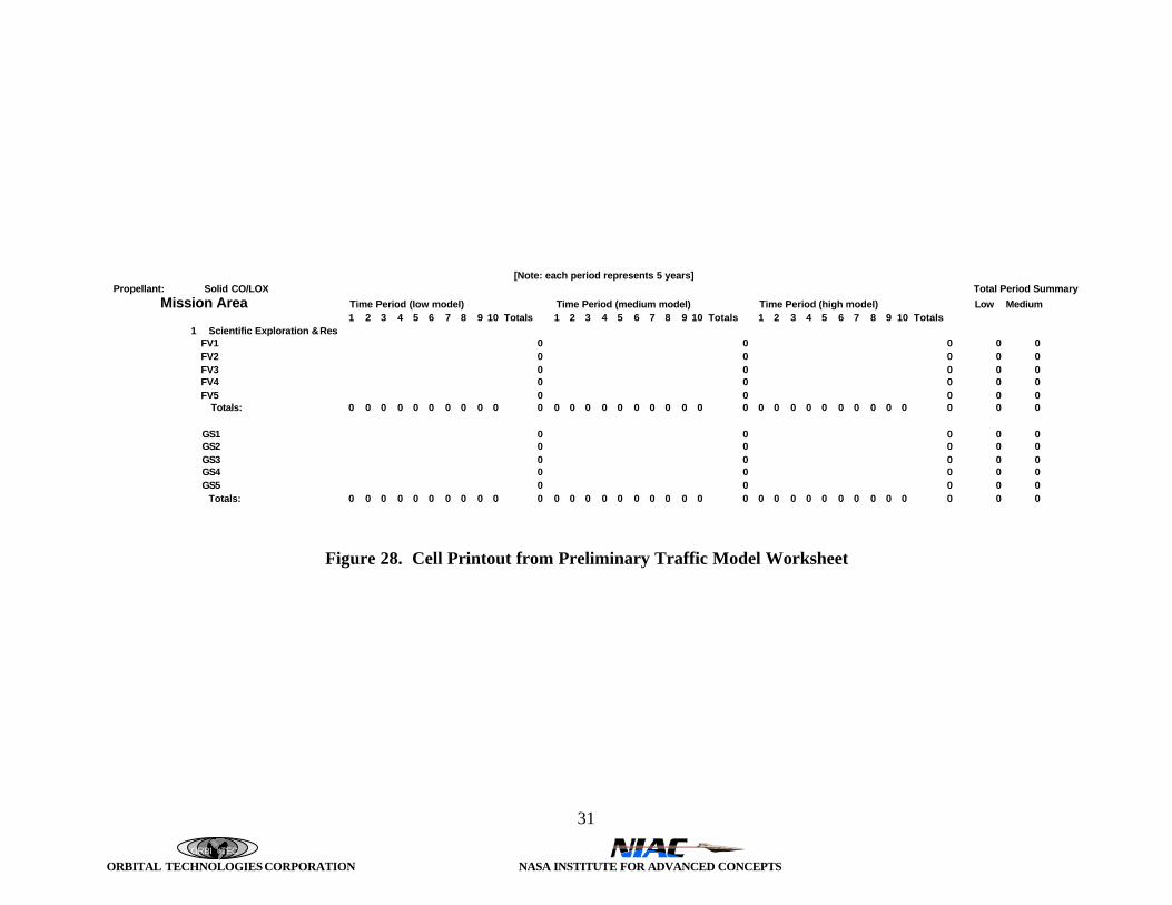
Once we have assigned a defined vehicle to the mission, the next task is to identify how often themission needs to be accomplished. Figure 28 shows a cell printout from Excel spreadsheet thatwas created in Phase I to eventually provide the means to input the traffic model of all vehiclesfor the low, medium and high scenarios for the given mission categories and propellant family.
• Scientific Exploration & Research• Commercial Exploration• Terraforming• Infrastructure Construction• Agriculture/Farming• Manufacturing/Industrial Activities• Resource Mining• Weather/Environmental• Communications Navigation Services• Surveying/Mapping• Personal Transportation• Package/Mail Delivery/Product Delivery/Food
Delivery/Goods/Services/Cargo• Government Activity/Law Enforcement/Emergency Rescue/Response• Launch/Space Transport Satellite/Earth Cargo Launch/Space
Transport• Auxiliary Power/Emergency Power• Life Support• Waste/Trash Management• Health Care/Maintenance• Virtual Travel Market

ORBI TEC ORBITAL TECHNOLOGIES CORPORATION NASA INSTITUTE FOR ADVANCED CONCEPTS
Mission Category: Scientific Exploration and Research
Mission/Submission Scope? # of Crew/Robotic
MissionDuration
Distance fromBase (km)
TravelTime
PayloadMass (kg)
Vehicle TypeRequired
Past/Current Life on Mars – search for evidence of past life, geology of the planet, ice at poles or permafrost (tools, sample boxes, life support, rover, sample rocks/dust, measureseismic activity)
2/Robotic2/Robotic2/Robotic
1-5 days1 day
3-7 days
4000 km500 km
10,000 km
MinutesHours
Minutes
300300300
Ballistic FlightGround
Ballistic Flight
Meteorology – study/characterize atmosphere, dust storms, other weather Delivery VehiclePhenomena (temperate, pressure, wind velocity, solar radiation, humidity) Recovery Vehicle Sounding Rocket
RoboticRoboticRobotic
1 day1 day< day
10,000 km10,000 km? altitude
MinutesMinutesMinutes
10102
Ballistic FlightBallistic FlightBallistic Flight
Astronomy – any orbiting systems supplied from Earth- any ground-based systems located at base, so no requirement
for transport
Solar Monitoring – located at base, so no need for transport
Other Science – study meteorites, characterize poles 2/Robotic2/Robotic2/Robotic
1-5 days1 day
3-7 days
4000 km500 km
10,000 km
MinutesHours
Minutes
20050200
Ballistic FlightGround
Ballistic Flight
Mars Moon Exploration(landing equipment, tools similar to the search for life/geology mission)
3/Robotic 1 week Moon Orbits Hours 100 Flight vehicle
Mission to Asteroid Belt 3/Robotic Months Asteroid Belt Hours 100 Flight vehicle
Figure 27. Example of a Mars Mission Worksheet for Scientific Exploration and Research
ORBI TEC
ORBITAL TECHNOLOGIES CORPORATION NASA INSTITUTE FOR ADVANCED CONCEPTS
31
[Note: each period represents 5 years]Propellant: Solid CO/LOX Total Period Summary Mission Area Time Period (low model) Time Period (medium model) Time Period (high model) Low Medium
1 2 3 4 5 6 7 8 9 10 Totals 1 2 3 4 5 6 7 8 9 10 Totals 1 2 3 4 5 6 7 8 9 10 Totals1 Scientific Exploration &Res
FV1 0 0 0 0 0FV2 0 0 0 0 0FV3 0 0 0 0 0FV4 0 0 0 0 0FV5 0 0 0 0 0 Totals: 0 0 0 0 0 0 0 0 0 0 0 0 0 0 0 0 0 0 0 0 0 0 0 0 0 0 0 0 0 0 0 0 0 0 0
GS1 0 0 0 0 0GS2 0 0 0 0 0GS3 0 0 0 0 0GS4 0 0 0 0 0GS5 0 0 0 0 0 Totals: 0 0 0 0 0 0 0 0 0 0 0 0 0 0 0 0 0 0 0 0 0 0 0 0 0 0 0 0 0 0 0 0 0 0 0
Figure 28. Cell Printout from Preliminary Traffic Model Worksheet

ORBI TEC
ORBITAL TECHNOLOGIES CORPORATION NASA INSTITUTE FOR ADVANCED CONCEPTS
32
3.8 Vehicle/System Families Scenarios
After we have developed the mission, we will assign the appropriate type of vehicle to themission. The types of vehicles are listed below in Figure 29 under the three vehicle categories.
Flight Vehicles Ground Vehicles Power SystemsMAVs for Sample Return Automated Rovers TurbineBallistic Hoppers Personal Closed Rovers Fuel CellSurface to Orbit 2-Person Open RoversInterplanetary Multi-Person Closed RoverPowered Balloons Large Cargo TransportsWinged AerocraftSingle Rocket BackpacksSingle Rocket Platforms
Figure 29. Vehicle Categories to Be Considered to Satisfy Mission Requirements
For each of these vehicles, we will define a vehicle concept/design with an estimated dry payloadMars and propellant storage/use capability that will allow the mission to be satisfied. Forexample a hopper vehicle for LH2/LOX would be expected to be smaller and carry lesspropellant than an equivalent SCO/LOX-based hopper. In addition to these vehicles, theinfrastructure/support systems also have to be conceptualized.
Examples of vehicles defined for mission applications are provided in the next section of thereport.
3.9 Assignment of Vehicles/Systems to Missions and Traffic/Use Model
In the all-up study that we are planning for Phase II, the assignment of the defined vehicle typesand sizes (propellant dependant) and infrastructure/ISRU systems would be made and a trafficmodel developed such that costs can be determined. Obviously, in Phase I we did not have theresources to do a complete analysis. Therefore, we chose to pick 4 missions and definevehicles/systems that could provide us some cost-benefit answers based on an estimated ELMcost. Four systems were defined; they were:
• MAV Replacement for Mars Sample Return Mission
• Ballistic Surface Hopper, Assuming H/O, CO/O,CH4/O,C/O and Single Stage, 1000 KgPayload, Fly to 500, 1000 Km Distances
• Rover/Transporter to 300 Km Distance Once Per Day, Using Fuel Cell or Brayton Cycle
• Outpost Chemical Power Using Fuel Cell or Brayton Cycle and H/O, CO/O, CH4/O,CH3OH/O
In the sections that follow, these four applications are analyzed and characterized.

ORBI TEC
ORBITAL TECHNOLOGIES CORPORATION NASA INSTITUTE FOR ADVANCED CONCEPTS
33
3.9.1 TSTO Mars Ascent Vehicle (MAV)
The effects of using different terrestrial and ISRU propellants were explored by determining themass characteristics of a two-stage-to orbit (TSTO) Mars Ascent Vehicle (MAV) for a variety ofpropellant and engine combinations. The analysis included an estimation of the propellant,vehicle, and ELM required for each system. The mission characteristics and vehicle assumptionscommon to all propellants are summarized in Table 4. The overall MAV mission is to place a3.6-kg payload into orbit for retrieval by an Earth-bound vehicle. The initial launch velocityrefers to the velocity supplied by the rotation of Mars at the launch site. As a first approximationfor the Phase I effort, the subsystem masses were assumed to be the same for each MAV,comprised of the power systems; guidance, navigation, and control; thermal control; auxiliarycold gas propulsion; and structures. A rendering of one possible MAV configuration is shown inFigure 30.
Table 4. Mission Characteristicsand Assumptions
Orbit: 600 kmOrbit Type: CircularPayload Mass: 3.6 kgStage 1 Subsystem Mass: 16.9 kgStage 2 Subsystem Mass: 1.7 kgInitial Launch Velocity: 241 m/sFirst Stage Delta-V: 2382 m/sSecond Stage Delta-V: 1514 m/sTotal Delta-V: 4137 m/s
Figure 30. TSTO Mars Ascent Vehicle
Performance characteristics for each system are summarized in Table 5. The propulsion systemmass fractions, defined by Equation 1, were assumed to be the same for bi-propellant and hybridsystems while those used for the solid system were slightly lower. The ideal ISP was calculated

ORBI TEC
ORBITAL TECHNOLOGIES CORPORATION NASA INSTITUTE FOR ADVANCED CONCEPTS
34
for each propellant combination using the NASA/GRC Chemical Equilibrium Analysis (CEA)program and the delivered ISP was determined by applying the appropriate efficiency for eachtype of propulsion system. No attempt was made to optimize the mixture ratio from a systemspoint of view; the engines were assumed to run at the mixture ratio yielding the highest ISP. Anexplanation of the CEA performance calculations and results is given in Section 3.6.2.
(1) p
drypsps M
MMF ,=
where:
mass propellant total M
systempropulsionprimary of massdry M
fraction mass systempropulsion MF
p
dryps
ps
=
=
=
,
Table 5. Performance Characteristics for Each Propellant Combination
Propellants PropulsionSystem
MixtureRatio
Stage 1PSMF*
Stage 2PSMF*
ISP
Efficiency(%)
Stage 1DeliveredISP (sec)
Stage 2DeliveredISP (sec)
SCO/LOX Hybrid 0.57 0.27 0.66 92 253.7 267.0SC/LOX Hybrid 2.1 0.27 0.66 92 294.3 307.7
SC-H2/LOX** Hybrid 2.2 0.27 0.66 92 311.1 324.6
SC2H2/LOX Hybrid 1.8 0.27 0.66 92 355.6 368.6HTPB/LOX Hybrid 2.5 0.27 0.66 92 331.2 341.3
LCH4/LOX Bi-Propellant 3.2 0.27 0.66 95 367.0 381.6
CTPB binder Solid - 0.24 0.63 95 268.0 279.4*PSMF = Propulsion System Mass Fraction**Solid carbon with 5% H2 additive by mass
The Engineering Equation Solver (EES) software was employed to simultaneously solve for theMAV system unknowns for each propellant combination. The required program input andresulting output are listed below.
MAV Program InputØ Delivered ISP for stage 1Ø Delivered ISP for stage 2Ø Payload massØ Subsystem mass for stage 1Ø Subsystem mass for stage 2Ø Propulsion system mass fraction for stage 1Ø Propulsion system mass fraction for stage 2Ø Delivered Delta-V required by stage 1

ORBI TEC
ORBITAL TECHNOLOGIES CORPORATION NASA INSTITUTE FOR ADVANCED CONCEPTS
35
Ø Delivered Delta-V required by stage 2
MAV Program OutputØ Mass of propellant required for stage 1Ø Mass of propellant required for stage 2Ø Mass of stage 1 propulsion systemØ Mass of stage 2 propulsion system
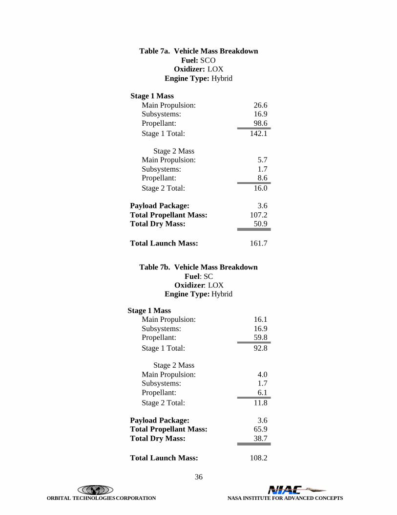
The results of the analysis are summarized in Table 6, including the propellant and vehicle drymasses; GLOW (Gross Lift Off Weight of the Mars Launch Mass); and ELM (Earth LaunchMass - the total mass of the MAV systems and propellant transported from Earth). Terrestrialpropellants are those which are transported to Mars from Earth, and ISRU propellants areassumed to be manufactured by existing Martian infrastructure, and hence, are not reflected inthe ELM. While carbon is available on Mars, it was assumed that the hydrogenated solid carbongrain was manufactured on Earth. The resulting grain is a highly storable, compact, and inertpackage, and eliminates the need to transport LH2, or manufacture it on Mars.
In this case it was assumed that the entire MAV system (minus any ISRU propellants) is broughtfrom Earth. However, these results do not take into account the various subsystems that wouldbe required for transporting the different propellants. In this regard, the more storable solidcarbon, HTPB, and solid grains would require less thermal control and packaging than the liquidhydrogen. Note that in the case of a pure ISRU propellant all of the chemicals are derived fromthe Martian environment, as in the case of SCO/LOX, rendering the vehicle dry mass identical tothe ELM. The ELM is reduced between 42-68% through the use of ISRU, depending upon thepropellant combination. Per the aforementioned ground rules, the lowest ELM for the casesconsidered here would be realized by the use of solid acetylene, reducing the ELM to 32.1 kg.As expected, the largest ELM is associated with the only non-ISRU system considered (solid)where the ELM is well over twice as high as for the heaviest of the ISRU systems. Moredetailed mass breakdowns for most systems are given in Tables 7a through 7f (mass is in kg).
Table 6. Summary of MAV AnalysisPropellant
CombinationPropulsionSystem
TerrestrialPropellants
PropellantMass (kg)
Dry Mass*
(kg)GLOW
(kg)ELM (kg)
SCO/LOX Hybrid - 107.2 50.9 161.7 50.9SC/LOX Hybrid - 65.9 38.7 108.2 38.7SC-H2/LOX** Hybrid C, H2 56.3 36.0 95.9 53.3SC2H2/LOX Hybrid H2 40.4 31.0 75.0 32.1HTPB/LOX Hybrid HTPB 48.2 33.5 85.3 47.3LCH4/LOX Bi-Propellant H2 37.5 30.2 71.3 32.4CTPB binder Solid Solid 81.3 40.7 125.6 122.0
*Dry mass does not include 3.6 kg payload**SC with 5% H2 additive by mass
ORBI TEC
ORBITAL TECHNOLOGIES CORPORATION NASA INSTITUTE FOR ADVANCED CONCEPTS
36
Table 7a. Vehicle Mass BreakdownFuel: SCO
Oxidizer: LOXEngine Type: Hybrid
Stage 1 MassMain Propulsion: 26.6Subsystems: 16.9Propellant: 98.6Stage 1 Total: 142.1
Stage 2 MassMain Propulsion: 5.7Subsystems: 1.7Propellant: 8.6Stage 2 Total: 16.0
Payload Package: 3.6Total Propellant Mass: 107.2Total Dry Mass: 50.9
Total Launch Mass: 161.7
Table 7b. Vehicle Mass BreakdownFuel: SC
Oxidizer: LOXEngine Type: Hybrid
Stage 1 MassMain Propulsion: 16.1Subsystems: 16.9Propellant: 59.8Stage 1 Total: 92.8
Stage 2 MassMain Propulsion: 4.0Subsystems: 1.7Propellant: 6.1Stage 2 Total: 11.8
Payload Package: 3.6Total Propellant Mass: 65.9Total Dry Mass: 38.7
Total Launch Mass: 108.2

ORBI TEC
ORBITAL TECHNOLOGIES CORPORATION NASA INSTITUTE FOR ADVANCED CONCEPTS
37
Table 7c. Vehicle Mass BreakdownFuel: SC with 5% H2 additive (by mass)
Oxidizer: LOXEngine Type: Hybrid
Stage 1 MassMain Propulsion: 13.8Subsystems: 16.9Propellant: 50.9Stage 1 Total: 81.6
Stage 2 MassMain Propulsion: 3.6Subsystems: 1.7Propellant: 5.4Stage 2 Total: 10.7
Payload Package: 3.6Total Propellant Mass: 56.3Total Dry Mass: 36.0
Total Launch Mass: 95.9
Table 7d. Vehicle Mass BreakdownFuel: LCH4
Oxidizer: LOXEngine Type: Bi-Propellant
Stage 1 MassMain Propulsion: 9.0Subsystems: 16.9Propellant: 33.6Stage 1 Total: 59.5
Stage 2 MassMain Propulsion: 2.6Subsystems: 1.7Propellant: 3.9Stage 2 Total: 8.2
Payload Package: 3.6Total Propellant Mass: 37.5Total Dry Mass: 30.2
Total Launch Mass: 71.3

ORBI TEC
ORBITAL TECHNOLOGIES CORPORATION NASA INSTITUTE FOR ADVANCED CONCEPTS
38
Table 7e. Vehicle Mass BreakdownPropellant: CTPBEngine Type: Solid
Stage 1 MassMain Propulsion: 17.5Subsystems: 16.9Propellant: 74.0Stage 1 Total: 108.4
Stage 2 MassMain Propulsion: 4.6Subsystems: 1.7Propellant: 7.3Stage 2 Total: 13.6
Payload Package: 3.6Total Propellant Mass: 81.3Total Dry Mass: 40.7
Total Launch Mass: 125.6
Table 7f. Vehicle Mass BreakdownFuel: SC2H2
Oxidizer: LOXEngine Type: Hybrid
Stage 1 MassMain Propulsion: 9.8Subsystems: 16.9Propellant: 36.2Stage 1 Total: 62.9
Stage 2 MassMain Propulsion: 2.8Subsystems: 1.7Propellant: 4.2Stage 2 Total: 8.7
Payload Package: 3.6Total Propellant Mass: 40.4Total Dry Mass: 31.0
Total Launch Mass: 75.0

ORBI TEC
ORBITAL TECHNOLOGIES CORPORATION NASA INSTITUTE FOR ADVANCED CONCEPTS
39
3.9.2 Martian Hopper Analysis
The effects of using different terrestrial and ISRU propellants were also explored by determiningthe mass characteristics of a Mars ballistic hopper for four propellant combinations. Theanalysis included an estimation of the amount of propellant, vehicle mass, and earth launch massrequired for each system. The hopper is designed to transport personnel, supplies, andequipment from one base to another, using a powered landing, refueling at each base.
Analysis was conducted to determine the optimum launch angle and required propulsion systemdelta-V for a given trip distance. The geometry of a ballistic trajectory is defined in Figure 31.From the initial value problem (Thomson, pp. 93), the angular position can be shown to be:
( )( ) 1cosKRv
cossinKRv2
tano
22o
oo2o
−β
ββ−=
φ
The optimum βο and minimum ∆V can be found by solving the above equation for vo, taking thederivative of the resulting equation with respect to βo, and setting the numerator equal to zero:
φ
=β2
cotarctan21
o
( )( )
β+
β=
o
omin 2cos1
2cos2RK
v
The eccentricity of the elliptical path, the height of apogee, and the time of flight can also bedetermined by following Thomson’s analysis in Section 4.17.
Figure 31. Geometry of Ballistic Trajectory

ORBI TEC
ORBITAL TECHNOLOGIES CORPORATION NASA INSTITUTE FOR ADVANCED CONCEPTS
40
With the velocity increment known, the rocket equation can be used to determine the vehiclemass fraction (neglecting gravity and drag losses):
∆=
gIv
expMM
spf
i
The following charts (Figures 32-40) were produced using a spreadsheet analysis of this basicapproach and allows the payload mass, structural mass fraction, and propellant specific impulseto vary parametrically.
∆∆V and Optimum Heading Angle for Mars Hopper on Ballistic Trajectories
0
500
1000
1500
2000
2500
3000
3500
4000
0 1000 2000 3000 4000 5000 6000 7000 8000 9000 10000
Range, km
∆∆V
, m
/s
0
5
10
15
20
25
30
35
40
45
50
Optim
um H
eading Angle, ββo
Figure 32. Delta V and Optimum Heading Angle for Mars Hopper

ORBI TEC
ORBITAL TECHNOLOGIES CORPORATION NASA INSTITUTE FOR ADVANCED CONCEPTS
41
Apogee and Time of Flight for Mars Hopper on Ballistic Trajectories
0
100
200
300
400
500
600
700
800
0 1000 2000 3000 4000 5000 6000 7000 8000 9000 10000
Range, km
Apo
gee,
km
0
500
1000
1500
2000
2500
3000
3500
Tim
e of F
ligh
t, s
Figure 33. Apogee and Time of Flight for Mars Hopper
Overall Mass Fractions (M f/Mi) for Mars Hopper on Ballistic Trajectories
0.000
0.100
0.200
0.300
0.400
0.500
0.600
0 1000 2000 3000 4000 5000 6000 7000 8000 9000 10000
Range, km
Mf/M
i
LOX/H2
LOX/CH4
LOX/CO
Single Stage1000 kg payloadStructural Mass Fraction = 0.10
CO 2/AL
Figure 34. Overall Mass Fractions for Mars Hopper

ORBI TEC
ORBITAL TECHNOLOGIES CORPORATION NASA INSTITUTE FOR ADVANCED CONCEPTS
42
Propellant Mass Fractions (Mp/Mi) for Mars Hopper on Ballistic Trajectories
0.400
0.500
0.600
0.700
0.800
0.900
1.000
0 1000 2000 3000 4000 5000 6000 7000 8000 9000 10000
Range, km
Mp/
Mi
Single Stage1000 kg payloadStructural Mass Fraction = 0.10
LOX/H2
LOX/CH4
LOX/CO
CO2/AL
Figure 35. Propellant Mass Fractions for Mars Hopper
Payload Mass Fractions (Mpay/Mi) for Mars Hopper on Ballistic Trajectories
0.000
0.050
0.100
0.150
0.200
0.250
0.300
0.350
0.400
0.450
0.500
0 1000 2000 3000 4000 5000 6000 7000 8000 9000 10000
Range, km
Mpa
y/M
i
Single Stage1000 kg payloadStructural Mass Fraction = 0.10
LOX/H2
LOX/CH4
LOX/CO
CO2/AL
Figure 36. Payload Mass Fractions for Mars Hopper

ORBI TEC
ORBITAL TECHNOLOGIES CORPORATION NASA INSTITUTE FOR ADVANCED CONCEPTS
43
Vehicle Masses for Mars Hopper on Ballistic TrajectoriesUsing LOX/LH2
0
2000
4000
6000
8000
10000
12000
0 1000 2000 3000 4000 5000 6000 7000 8000 9000 10000
Range, km
Mas
s, k
g
Initial
Propellant
Final
Structure
Single Stage1000 kg payloadStructural Mass Fraction = 0.10Isp = 451 s
Figure 37. Vehicle Masses for Mars Hopper using LOX/LH2
Vehicle Masses for Mars Hopper on Ballistic TrajectoriesUsing LOX/CH4
0
5000
10000
15000
20000
25000
0 1000 2000 3000 4000 5000 6000 7000 8000 9000 10000Range, km
Mas
s, k
g
Single Stage1000 kg payloadStructural Mass Fraction = 0.10Isp = 370 s
Initial
Propellant
Final
Structure
Figure 38. Vehicle Masses for Mars Hopper using LOX/CH4

ORBI TEC
ORBITAL TECHNOLOGIES CORPORATION NASA INSTITUTE FOR ADVANCED CONCEPTS
44
Vehicle Masses for Mars Hopper on Ballistic TrajectoriesUsing LOX/CO
(Can Not Complete 5,000 and 10,000 km Missions)
0
200
400
600
800
1000
1200
1400
1600
1800
2000
0 500 1000 1500 2000 2500 3000
Range, km
Mas
s, k
g
Single Stage1000 kg payloadStructural Mass Fraction = 0.10Isp = 285 s
Initial
Propellant
FinalStructure
Figure 39. Vehicle Masses for Mars Hopper using LOX/CO
Vehicle Masses for Mars Hopper on Ballistic TrajectoriesUsing CO2/AL
(Can Not Complete 5,000 and 10,000 km Missions)
0
1000
2000
3000
4000
5000
6000
7000
8000
9000
10000
0 500 1000 1500
Range, km
Mas
s, k
g
Single Stage1000 kg payloadStructural Mass Fraction = 0.10Isp = 230 s
Initial
Propellant
Final
Structure
Figure 40. Vehicle Masses for Mars Hopper using CO2/Al

ORBI TEC
ORBITAL TECHNOLOGIES CORPORATION NASA INSTITUTE FOR ADVANCED CONCEPTS
45
Three specific hopper distances were selected for comparison: 500, 1000, and 2500 km. Thetotal vehicle delta-V required for a one-way trip with a powered landing is shown in Table 8 foreach case. The total non-propulsion hopper mass, comprised of a two-man crew, life support,transport payload, and miscellaneous vehicle systems and supplies, was assumed to be the samefor all distances and propellants. A mass summary is shown in Table 9 and a rendering of onepossible hopper configuration is shown in Figure 41. This mass breakdown is assumed for allhopper results presented in this section.
Table 8. Delta-V RequiredTrip Distance
(km)Total Vehicle Delta-V
Required(km/sec)
500 26361000 36002500 5168
Table 9. Hopper Mass BreakdownDescription Mass (kg)
Two Man Crew: 158.8Crew Cabin and Life Support: 453.6Transport Payload: 1000Misc. Vehicle Systems and Supplies: 260.3
Total Non Propulsion Hopper Mass: 1873

ORBI TEC
ORBITAL TECHNOLOGIES CORPORATION NASA INSTITUTE FOR ADVANCED CONCEPTS
46
Figure 41. Mars Ballistic Hopper
The amount of propellant required, propulsion system mass (propellant tanks, engine, fluiddelivery system, and nozzle) and total vehicle mass were parametrically calculated as a functionof the propellant combination, structural mass fraction (defined by Equation 2), and trip distance,using the rocket equation. Specific impulse, efficiency, and mixture ratio data for the propellantswere the same as shown in Table 2 for the second stage of the MAV, for LH2/LOX: ISP = 436sec, delivered ISP efficiency = 95%, and O/F ratio = 6.0.
(2) drypsp
drypss MM
MMF
,
,
+=
where:
mass propellant total M
systempropulsionprimary of massdry M
fraction mass l structuraMF
p
dryps
s
=
==
,
The results for a structural mass fraction of 0.10 are shown in Table 10 including the propellantand vehicle dry masses; GLOW (Ground Lift Off Weigh - the Mars Launch Mass); and ELM(Earth Launch Mass). Terrestrial propellants are those which are transported to Mars from Earth,

ORBI TEC
ORBITAL TECHNOLOGIES CORPORATION NASA INSTITUTE FOR ADVANCED CONCEPTS
47
and ISRU propellants are assumed to be manufactured by existing Martian infrastructure andhence are not reflected in the ELM. In this case it is assumed that the fully equipped hoppervehicles are also Martian infrastructure, and do not factor into the ELM calculation.
The GLOW increases exponentially with the distance traveled due to the need to acceleratelarger amounts of propellants, including the propellant required for the powered landing. It alsoappears that the lower performing propellants, which are more easily derived from the Martianenvironment, are more attractive for the shorter trips. For example, the mass of SCO/LOXrequired for a 500 km trip is 2.3 times that of the LH2/LOX system whereas this ratio jumps to6.3 for the 2500-km trip. There is a similar affect on the mass of the propulsion system that isreflected in the dry mass listed in the table.
Table 10. Summary of Martian Hopper Analysis for a Structural Mass Fraction = 0.10Propellant PROPULSION
SystemTerrestrialPropellants
DISTANCE(km)
PropellantMass (kg)
DRYMass(kg)
GLOW(kg)
ELM(kg)
SCO/LOX Hybrid - 500 4040 2320 6360 0
SC/LOX Hybrid - 500 3090 2220 5310 0
LCH4/LOX Bi-Propellant H2 500 2160 2110 4270 129
LH2/LOX Bi-Propellant H2, O2 500 1760 2070 3830 1760
SCO/LOX Hybrid - 1000 8250 2790 11,040 0
SC/LOX Hybrid - 1000 5770 2520 8290 0
LCH4/LOX Bi-Propellant H2 1000 3690 2280 5970 220
LH2/LOX Bi-Propellant H2, O2 1000 2900 2190 5090 2900
SCO/LOX Hybrid - 2500 37,470 6040 43,510 0
SC/LOX Hybrid - 2500 17,170 3780 20,950 0
LCH4/LOX Bi-Propellant H2 2500 8320 2800 11,120 500
LH2/LOX Bi-Propellant H2, O2 2500 5950 2530 8480 5950
The effects of varying the structural mass fraction were also explored. Figures 42 through 44 area plot of the mass of propellant required vs. structural mass fraction for the three trip distances.Note that as the structural mass fraction increases, the lower performing SCO/LOX pays a higherpenalty than the other two systems. Conversely, the SCO/LOX system will benefit much moreby future materials and system technology that reduce the overall weight of the propulsionsystem. This is most clearly illustrated by Figure 44.

ORBI TEC
ORBITAL TECHNOLOGIES CORPORATION NASA INSTITUTE FOR ADVANCED CONCEPTS
48
0
1000
2000
3000
4000
5000
6000
0.05 0.075 0.1 0.125 0.15Structural Mass Fraction
Tot
al P
rop
ella
nt
Mas
s (k
g)LH2/LOXLCH4/LOXSCO/LOX
Figure 42. Total Propellant Mass Required for a 500 km Ballistic Hop vs. Structural MassFraction
0
2000
4000
6000
8000
10000
12000
0.05 0.075 0.1 0.125 0.15
Structural Mass Fraction
Tot
al P
rop
ella
nt
Mas
s (k
g)
LH2/LOXLCH4/LOXSCO/LOX
Figure 43. Total Propellant Mass Required for a 1000 km

ORBI TEC
ORBITAL TECHNOLOGIES CORPORATION NASA INSTITUTE FOR ADVANCED CONCEPTS
49
0
10000
20000
30000
40000
50000
60000
0.05 0.075 0.1 0.125 0.15Structural Mass Fraction
Tot
al P
rop
ella
nt
Mas
s (k
g)LH2/LOX
LCH4/LOX
SCO/LOX
Figure 44. Total Propellant Mass Required for a 2500 km Ballistic Hop vs. StructuralMass Fraction
3.9.3 Rover
A rover was conceptualized and is shown is Figure 45.
Figure 45. ISRU Powered Rover
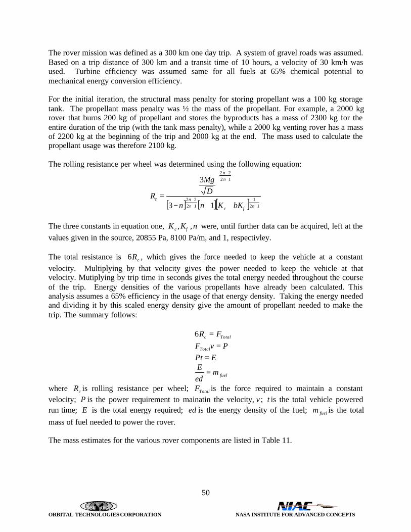
ORBI TEC
ORBITAL TECHNOLOGIES CORPORATION NASA INSTITUTE FOR ADVANCED CONCEPTS
50
The rover mission was defined as a 300 km one day trip. A system of gravel roads was assumed.Based on a trip distance of 300 km and a transit time of 10 hours, a velocity of 30 km/h wasused. Turbine efficiency was assumed same for all fuels at 65% chemical potential tomechanical energy conversion efficiency.
For the initial iteration, the structural mass penalty for storing propellant was a 100 kg storagetank. The propellant mass penalty was ½ the mass of the propellant. For example, a 2000 kgrover that burns 200 kg of propellant and stores the byproducts has a mass of 2300 kg for theentire duration of the trip (with the tank mass penalty), while a 2000 kg venting rover has a massof 2200 kg at the beginning of the trip and 2000 kg at the end. The mass used to calculate thepropellant usage was therefore 2100 kg.
The rolling resistance per wheel was determined using the following equation:
[ ] [ ][ ] 121
1222
1222
13
3
+++
++
++−
=ncn
n
nn
c
bKKnn
DMg
Rφ
The three constants in equation one, nKK c ,, φ were, until further data can be acquired, left at thevalues given in the source, 20855 Pa, 8100 Pa/m, and 1, respectivley.
The total resistance is cR6 , which gives the force needed to keep the vehicle at a constantvelocity. Multiplying by that velocity gives the power needed to keep the vehicle at thatvelocity. Mutiplying by trip time in seconds gives the total energy needed throughout the courseof the trip. Energy densities of the various propellants have already been calculated. Thisanalysis assumes a 65% efficiency in the usage of that energy density. Taking the energy neededand dividing it by this scaled energy density give the amount of propellant needed to make thetrip. The summary follows:
Totalc FR =6
PvFTotal =EPt =
fuelmedE =
where cR is rolling resistance per wheel; TotalF is the force required to maintain a constantvelocity; P is the power requirement to mainatin the velocity, v ; t is the total vehicle poweredrun time; E is the total energy required; ed is the energy density of the fuel; fuelm is the total
mass of fuel needed to power the rover.
The mass estimates for the various rover components are listed in Table 11.

ORBI TEC
ORBITAL TECHNOLOGIES CORPORATION NASA INSTITUTE FOR ADVANCED CONCEPTS
51
Table 11. Rover Mass EstimationsRover Mass Summary
LightDuty
MidDuty
HeavyDuty
Life Support Hardware 32 32 32Pressurized Cabin 454 454 454Waste Management 2.3 2.3 2.3Medical Supplies 0.1 0.1 0.1Windows 0.5 0.5 0.5Crew Accommodations 11.5 11.5 11.5Lighting 0.1 0.1 0.1Radiation Shielding 18.1 18.1 18.1Water, Food and Oxygen 4 4 4
External Lighting 0.5 0.5 0.5Controls, Navigation,Avionics, Instruments, GPS
6 6 6
Wheels/Tires (Each) 5 7.5 10Frame 150 600 1500Mechanical Delivery System 50 100 200
Cargo Bay (un-pressurized) 80 160 500
Insulation 9.1 9.1 9.1Electric Power Distribution 5 5 5
Turbine (kg/kJ) 1000 1500 2000Vehicle Mass 1339 2422 4264
Payload 1000 4000 10000Total Dry Mass 2339 6422 14264
Assessment of fuel needs for H2/O2, CH4/O2, and CO/O2 was made and is shown in Table 12below.
Table 12. Fuel Needs for a 300km, Ten-Hour Turbine-Powered, Rover Mission
Fuel Type H2 /O2 CH4 /O2 CO/O 2
Fuel Use, Exhaust
Recovered (kg)113* 154 (13*) 249
Fuel Use, Exhaust
Not Recovered (kg)104* 142 (12*) 223
* M a s s S u p p l i e d f r o m E a r t h o r M o o n a s H y d r o g e n

ORBI TEC
ORBITAL TECHNOLOGIES CORPORATION NASA INSTITUTE FOR ADVANCED CONCEPTS
52
3.9.4 Auxiliary Power
Use of CO/O2 in fuel cell energy production has already been proven feasible (AIAA Paper 98-0650, K. R. Sridhar), over the next century technology advances driven by attractiveness of thisprocess on Mars should drive efficiencies to 60% and higher with combined cycle processesutilizing waste heat for base/rover heating. Molten Carbonate fuel cells already have efficienciesclose to 85% for combined cycle hydrogen fuels (DOE), indicating that high efficiencies couldbe attained for an in situ CO/O2 system. The molten carbonate fuel cell has to be run in anelectrolyzer mode to remove chemisorbed CO from the catalyst, but this process is onlynecessary daily and occurs quickly. New catalysts can lessen or eliminate this problem as well.
Fuel cells have the capability of supplying power on demand without the rundown associatedwith low batteries and a modular design would provide for daily power fluctuations and for theincreased loads of a growing outpost. An RTG would be used for startup heating of the fuel celland for powering essential systems when the base is uninhabited; a battery or solar system wouldmost likely be invoked on a rover.
Parametric equations have been developed for varying fuel cell efficiencies and fuels of H2/O2,CO/O2, and CH4/O2. Calculations were preformed to determine the amounts of various fuelsneeded to power a Mars base at varying energy loads and production efficiencies. Thesecalculations only consider the energy density of the fuels, the base’s power load requirements,and the efficiency of the process in determining fuel requirements so the results can be applied toboth a fuel cell and turbine energy system. Existing power loads for Mir and the InternationalSpace Station are given in Table 13 as a reference, and power requirements are given inkWh/day. Fuel energy densities are given in kWh/kg fuel. The fuel requirements are thencalculated using the formula:
ηρe
EF =
where:F = Fuel Mass Required per DayE = Daily Base Energy Requirementρe = Fuel Energy Densityη = Efficiency

ORBI TEC
ORBITAL TECHNOLOGIES CORPORATION NASA INSTITUTE FOR ADVANCED CONCEPTS
53
Table 13. Fuel Requirements of a proposed Mars Outpost
Fuel Energy DensitiesISS: 105 kW 2520 kWh/day H2/O2 13500 kJ/kg = 3.75 kWh/kgMir: 30 kW 720 kWh/day CO/O2 6540 kJ/kg = 1.82 kWh/kg
CH4/O2 10080 kJ/kg = 2.80 kWh/kg
Turbine/Fuel Cell Combined Cycle Fuel RequirementsFacility
kWh/day CO/O2 CH4/O2 H2/O2 CO/O2 CH 4/O2 H2/O2 CO/O2 CH4/O2 H 2/O2 CO/O2 CH4/O2 H2/O2 CO/O2 CH 4/O2 H2/O2 CO/O2 CH4/O2 H2/O2
1200 1651 1071 800 1321 857 640 1101 714 533 944 612 457 826 536 400 734 476 4571440 1982 1286 960 1585 1029 768 1321 857 640 1132 735 549 991 643 480 881 571 5491680 2312 1500 1120 1850 1200 896 1541 1000 747 1321 857 640 1156 750 560 1028 667 6401920 2642 1714 1280 2114 1371 1024 1761 1143 853 1510 980 731 1321 857 640 1174 762 7312160 2972 1929 1440 2378 1543 1152 1982 1286 960 1699 1102 823 1486 964 720 1321 857 8232400 3303 2143 1600 2642 1714 1280 2202 1429 1067 1887 1224 914 1651 1071 800 1468 952 9142640 3633 2357 1760 2906 1886 1408 2422 1571 1173 2076 1347 1006 1817 1179 880 1615 1048 10062880 3963 2571 1920 3171 2057 1536 2642 1714 1280 2265 1469 1097 1982 1286 960 1761 1143 10973120 4294 2786 2080 3435 2229 1664 2862 1857 1387 2453 1592 1189 2147 1393 1040 1908 1238 11893360 4624 3000 2240 3699 2400 1792 3083 2000 1493 2642 1714 1280 2312 1500 1120 2055 1333 12803600 4954 3214 2400 3963 2571 1920 3303 2143 1600 2831 1837 1371 2477 1607 1200 2202 1429 13713840 5284 3429 2560 4228 2743 2048 3523 2286 1707 3020 1959 1463 2642 1714 1280 2349 1524 14634080 5615 3643 2720 4492 2914 2176 3743 2429 1813 3208 2082 1554 2807 1821 1360 2495 1619 15544320 5945 3857 2880 4756 3086 2304 3963 2571 1920 3397 2204 1646 2972 1929 1440 2642 1714 16464560 6275 4071 3040 5020 3257 2432 4183 2714 2027 3586 2327 1737 3138 2036 1520 2789 1810 17374800 6606 4286 3200 5284 3429 2560 4404 2857 2133 3775 2449 1829 3303 2143 1600 2936 1905 1829
kg Fuel at 70% Efficiency kg Fuel at 80% Efficiency kg Fuel at 90% Efficiency
Current Space Requirements
kg Fuel at 50% Efficiency kg Fuel at 60% Efficiencykg Fuel at 40% Efficiency
An analysis of fuel requirements for base energy loads at various efficiencies were calculated foreach prospective fuel system, with the results for the CO/O2 system given in Figure 46, CH4/O2
in Figure 47, and H2/O2 in Figure 48. For a 70% efficient process, the fuels’ energy densitieswere contrasted in Figure 49.
CO/O System Fuel Requirements at Various Efficiencies
0
1000
2000
3000
4000
5000
6000
7000
0 1000 2000 3000 4000 5000 6000Power Requirements (kWh/day)
Mas
s of
Fue
l (kg
)
40% Efficiency
50% Efficiency
60% Efficiency
70% Efficiency
80% Efficiency
90% Efficiency
Figure 46. CO/O2 System Fuel Requirements at Various Efficiencies

ORBI TEC
ORBITAL TECHNOLOGIES CORPORATION NASA INSTITUTE FOR ADVANCED CONCEPTS
54
0
500
1000
1500
2000
2500
3000
3500
4000
4500
0 1000 2000 3000 4000 5000 6000Power Requirements (kWh/day)
Mas
s of
Fue
l (kg
)40% Efficiency
50% Efficiency
60% Efficiency
70% Efficiency
80% Efficiency
90% Efficiency
Figure 47. CH4/O2 System Fuel Requirements at Various Efficiencies
0
500
1000
1500
2000
2500
3000
3500
0 1000 2000 3000 4000 5000 6000Power Requirements (kWh/day)
Mas
s of
Fue
l (kg
)
40% Efficiency
50% Efficiency
60% Efficiency
70% Efficiency
80% Efficiency
90% Efficiency
Figure 48. H2/O2 System Fuel Requirements at Various Efficiencies

ORBI TEC
ORBITAL TECHNOLOGIES CORPORATION NASA INSTITUTE FOR ADVANCED CONCEPTS
55
0
500
1000
1500
2000
2500
3000
3500
4000
0 1000 2000 3000 4000 5000 6000
Power Requirements (kWh/day)
Fuel
Mas
s (k
g/da
y)
CO/O2
CH4/O2
H2/O2
Figure 49. Fuel Requirements for System Power at 70% Overall Efficiency
3.10 Cost Models/Cost-Benefit Analysis
3.10.1 Cost Models
Several cost estimating models were investigated during the Phase I effort for use in Phase II. Abrief description of some of these models is listed below.
Advanced Missions Cost Model♦ This is a simple online advanced missions cost model (AMCM) that provides a useful
method for quick turnaround, rough-order-of-magnitude estimating. The model can be usedfor estimating the development and production cost of spacecraft, space transportationsystems, aircraft, missiles, ships, and land vehicles.
Cost Estimating Guidelines♦ Online guide to cost estimating practices and principles
Cost Spreading Calculator♦ This is a simple online cost spreading calculator that can be used to spread the estimated cost
of a program up to 8 years. The calculator uses a beta curve to determine the amount ofmoney to be spent in each year based on the fraction of the total time that has elapsed. Theuser enters the total cost to be spread, the beginning and ending years.

ORBI TEC
ORBITAL TECHNOLOGIES CORPORATION NASA INSTITUTE FOR ADVANCED CONCEPTS
56
DSN Cost Estimating Cost Model♦ This is a simple on-line model for estimating the cost required to do a cost estimate for Deep
Space Network (DSN) projects that range from $0.1 to $100 million. The cost of the costestimate in thousands of dollars, CE, is found to be approximately given by CE = K*CP^0.35 where CP is the cost of the project being estimated in millions of dollars and K is aconstant depending on the accuracy of the estimate. For an order-of-magnitude estimate, K =24; for a budget estimate, K = 60; and for a definitive estimate, K = 115. That is, for aspecific project, the cost of doing a budget estimate is about 2.5 times as much as that for anorder-of-magnitude estimate, and a definitive estimate costs about twice as much as a budgetestimate. Use of this model should help provide the level of resources required for doing costestimates and, as a result, provide insights towards more accurate estimates with lesspotential for cost overruns.
Expendable Launch Vehicles - International and US♦ Online data♦ Gives an estimate of launch cost vs. vehicle used, orbit achieved, and payload weight in
FY94$
Inflation Collectors♦ Wide variety of different inflation calculators
Learning Curve Calculator♦ The calculator uses the learning curve to estimate the unit, average, and total effort required
to produce a given number of units. Effort can be expressed in terms of cost, man-hours, orany other measure of effort. The calculator can be set to compute the Wright learning curveor the Crawford learning curve. The user is required to enter the effort (in terms of cost, man-hours, etc.) required to produce the first unit, the total number of units, and the learningpercent.
Missions Cost Operations Cost Model♦ This is a simple online mission operations cost model (MOCM) that provides a useful
method for quick turnaround, rough-order-of-magnitude cost estimating. The model can beused for estimating the mission operations cost of manned, unmanned, and planetaryspacecraft. The MOCM is based on NASA data for spacecraft flown between 1962 and 1990.The MOCM provides an estimate of the basic mission operations and data analysis (MODA)cost for a given spacecraft. MODA is defined as the cost of: maintaining and upgradingground systems; mission control; tracking; telemetry; command functions; mission planning;data reduction and analysis; crew training and related activities. The MOCM does not includethe cost of launch vehicles or launch services. The model estimates the average annualMODA based on the type of mission and the investment cost of the spacecraft. Theinvestment cost is defined as the total development and production cost of the spacecraft,experiments and ground systems. Note that the investment cost does not include launchvehicle or service costs.
NASA/Air Force Cost Model

ORBI TEC
ORBITAL TECHNOLOGIES CORPORATION NASA INSTITUTE FOR ADVANCED CONCEPTS
57
♦ The NAFCOM96 Cost Model is an innovative computer model for estimating aerospaceprogram costs. NAFCOM96 is a user friendly estimating tool which operates in theMicrosoft Windows environment. The model gives users flexibility in estimating byaccommodating up to five systems and ten WBS levels, and by providing the user with theoption of inputting hardware or integration cost or allowing the model to calculate the costusing NAFCOM96 estimating methodology or user defined equations.
Small Satellite Cost Model♦ The Small Satellite Cost Model, SSCM, is a parametric cost model which runs on any
Microsoft Excel-supported platform. The latest version, SSCM98, estimates the developmentand production costs of a small satellite bus for Earth-orbiting or near-planetary spacecraft.
Space Operations Cost Model♦ NASA’s Space Operations Cost Model (SOCM) study team is currently developing a suite of
tools to estimate space mission operations costs for future NASA projects. The estimatingmethodology is based on a mix of parametric estimating relationships derived from collecteddata and constructive approaches capturing assessments of advanced technology impacts andreflecting experience from current mission planning teams. The study team includes cost,technical, and programmatic experts from each NASA Center.
Spacecraft/Vehicle Level Cost Model♦ This is a simple on-line cost model that provides a useful method for quick turnaround,
rough-order-of-magnitude cost estimating. The model can be used for estimating thedevelopment and production cost of spacecraft, launch vehicle stages, engines and scientificinstruments. The SVLCM is a top-level model derived from the NASA/Air Force CostModel (NAFCOM) database.
TRANSCOST Model♦ This model is designed for the initial conceptual design phase of all propulsive space
transportation system elements and engines. It is a "transparent model" with graphicaldisplay of the reference data that is based on a comprehensive 30-year database from US andEuropean space vehicle and engine projects. TRANSCOST is a system-level model, basedon the actual cost of completed projects with careful data evaluation for analytical processingand application of specific regression factors.
3.10.2 Cost-Benefit Analysis
Table 14 presents a cost-benefit comparison of propellants under consideration for use on Mars.An Earth launch mass (ELM) cost of $10,000/kg was assumed. The ISRU savings is thedifference between the cost to launch a baseline (completely Earth-supplied) mission and thecost to launch the ISRU mission. Carbon and oxygen availability on Mars is assumed; hydrogenwould be from Earth. Propellant/propulsion combinations, mass requirements and missionprofiles were originally presented for the MAV (Table 6), hopper (Table 10), rover (Table 12)and outposts (Table13). The outpost is assumed occupied 50 days per year. The ISRU costsavings for the Mars hoppers and rovers are significant.

ORBI TEC
ORBITAL TECHNOLOGIES CORPORATION NASA INSTITUTE FOR ADVANCED CONCEPTS
58
Table 14. Cost-Benefit Comparison of ISRU Propellants
MissionELM per Mission
(kg)
ELM Cost
($M)
ISRU Savings per
Mission ($M)
Missions
per Year
ISRU Savings per
Year ($M)
MAV Sample ReturnBaseline Solid 122 1.22 ---- 1 ----SC2H2/LOX Hybrid 32.1 0.32 0.90 1 0.90LCH 4/LOX Bi-Prop 32.4 0.32 0.90 1 0.90SC/LOX Hybrid 38.7 0.39 0.83 1 0.83HTPB/LOX Hybrid 47.3 0.47 0.75 1 0.75SCO/LOX Hybrid 50.9 0.51 0.71 1 0.71SC-H2/LOX Hybrid 53.3 0.53 0.69 1 0.69
One Way Hopper (1000 km)
LH2/LOX Bi-Prop Baseline 2,900 29.0 ---- 10 ----LCH 4/LOX Bi-Prop 220 2.20 26.8 10 268SC/LOX Hybrid 0 0 29.0 10 290SCO/LOX Hybrid 0 0 29.0 10 290
Turbine Powered Rover (300km)
LH2/LOX Turbine Baseline 113 1.13 ---- 100 ----LCH 4/LOX Turbine 7.7 0.08 1.05 100 105SCO/LOX Turbine 0 0 1.13 100 113
Outpost Auxiliary Power
LH2/LOX Turbine Baseline 1400 14.00 ---- 50 ----LCH 4/LOX Turbine 100 1.00 13.00 50 650LCO/LOX Turbine 0 0 14.00 50 700
Note: Processing equipment not amortized over ISRU derived propellant ELM
3.11 Recommendations for ISRU Propellant Technology Development
Significant technology development will be required before the Mars ISRU architecture can beput into place. ORBITEC is proposing to determine the feasibility of two of the promisingpropellant performers (SC/LOX and SC2H2/LOX) by conducting small-scale rocket engine testfirings early in the Phase II so that they remain possible or are dropped from consideration.Propulsion technology for advanced cryogenic hybrids needs to be developed further thanORBITEC has taken it to date. The ORBITEC flight type LH2/SOX engine tests should provevery useful here. More work is needed to develop efficient cryogenic coolers to support ISRUmissions.
A significant amount of technology development in space-qualified ISRU processing systemswill be necessary and should begin now. Very small-scale-systems for the Mars 2001 Lander areto be flown; however, larger systems need to be flight qualified.
As a result of the Phase II architecture study, we expect to identify and subsequentlyrecommended technology development for critical times. The technology for processing thepropellants from the atmosphere appears to be in hand for CO and O2 production via theUniversity of Arizona. K. R. Sridhar has provided us data that indicates that electrolyticprocessing scales favorably as it get larger (see Section 3.6.3).

ORBI TEC
ORBITAL TECHNOLOGIES CORPORATION NASA INSTITUTE FOR ADVANCED CONCEPTS
59
4.0 CONCLUSIONS
The conclusions that have been made as a result of this Phase I NIAC study are as follows:
• ISRU will be a significant benefit to the Mars Exploration Program
• The SCO/LOX propellant system is likely good for short ballistic hops and wide use inground systems; it will likely require staging or other propellant saving measures forlarge orbital operations
• Improving mass fraction helps lower-performance systems
• Cryogenic solid grains can be made and stored in Mars propellant facilities
• CH4/LOX propellants are excellent for large orbital operations
• Carbon/LOX and acetylene hybrids also are excellent for more demanding missions andrequire further consideration
• H2/O2 systems would be best suited for high-performance missions, if Mars can supply it
• Large cargo transports are best accommodated by ground transport vehicles
• Ballistic rocket flight makes sense for high priority missions
• O/F choice can make a significant cost-benefit difference
• For ground-based systems, hydrogen in the exhaust can and should be recovered
• Consider savings attributed to wings, aeroshells, parachutes, etc
• Likely need nuclear power systems in many sizes
• The ISRU analysis approach we are pursuing is a complex problem
• Need to do a reasonable concept design on vehicles and process equipment to arrive atcorrect answer.

ORBI TEC
ORBITAL TECHNOLOGIES CORPORATION NASA INSTITUTE FOR ADVANCED CONCEPTS
60
5.0 RECOMMENDATIONS
This section presents ORBITEC's study recommendations that have been based on the Phase Iwork. Our recommendations are:
1. NIAC fund ORBITEC's proposed Phase II effort
2. Gain participation of key NASA staff in the Phase II Workshop
3. Gain participation of Dr. Robert Cassanova, NIAC Director, in the development of the Marspropellant architecture study workshop
4. Conduct feasibility testing for SC/GOX and SC2H2/GOX in Phase II
5. Carry out the system architecture study to determine the best overall ISRU approach
6. Study, analyze, and develop the most promising ISRU processing techniques
7. NIAC develop contact with Dr. Gerald Sanders, NASA/JSC, because of his significantinterest and responsibilities in NASA’s ISRU program.
ORBI TEC
ORBITAL TECHNOLOGIES CORPORATION NASA INSTITUTE FOR ADVANCED CONCEPTS
A-1
APPENDIX A
BIBLIOGRAPHY
ORBI TEC
ORBITAL TECHNOLOGIES CORPORATION NASA INSTITUTE FOR ADVANCED CONCEPTS
A-2
AIAA, “Need for a NASA Indigenous Space Resource Utilization (ISRU) Program,” An AIAAPosition Paper, Prepared by the AIAA Space Processing Technical Committee, January 6, 1997.
Ash, R., Dowler, W., and Varsi, G., “Feasibility of Rocket Propellant Production on Mars,” ActaAstronautica, Vol 5, pp. 705-724, 1978.
Carrick, P. G., “Specific Impulse Calculations of High Energy Density Solid Cryogenic RocketPropellants 1: Atoms in Solid H2,” Air Force Technical Report, PL-TR-93-3014, 1993. (a)
Clark, D.L., “In-Situ Propellant Production on Mars: A Sabatier/Electrolysis DemonstrationPlant”, AIAA 97-2764, 33rd AIAA/ASME/SAE/ASEE Joint Propulsion Conference and Exhibit,July, 1997.
Crow, Steven C., “The MOXCE Project: New Cells for Producing Oxygen on Mars”, AIAA 97-2766, 33rd AIAA/ASME/SAE/ASEE Joint Propulsion Conference & Exhibit, July 1997.
Forch, B., and Merrow, C., “Photodissociation Processes in Carbon Monoxide at 193 nm,”Journal of Chemistry Physics, Vol. 95, 1991.
French, J., “The Impact of Martian Propellant Manufacturing on Early Manned Exploration,”AAS 84-178, Proceedings of the Second Case for Mars Conference, Boulder, CO 1984.
Frisbee, R., French, J., and Lawton, E., “A New Look at Oxygen Production on Mars - In-SituPropellant Production (ISPP)” AIAA-87-0236, AIAA 25th Aerospace Sciences Meeting, January1987.
Guernsey, C, Thunnissen, D., and Adler, M, “Evaluation of Some Candidate PropulsionTechnologies for Mars Ascent”, AIAA 98-0651, 36th Aerospace Sciences Meeting & Exhibit,January 12-15, 1998, Reno NV.
Hepp, A., Landis, G., and Linne, D., “Material Processing with Hydrogen and Carbon Monoxideon Mars,” NASA TM 104405, May, 1991.
Jacobs, M., Deal, S., German, D., and Stancati, M., “An Assessment of In-Situ PropellantProduction for Low Cost Mars Sample Return,” SAIC Final Report SAIC-95/1158 on ContractNASW-4491. Presented to the Solar System Exploration Division, NASA HQ, April, 1995.
Linne, D., “Experimental Evaluation of the Ignition Process of Carbon Monoxide and Oxygen in aRocket Engine,” NASA TM 107267, AIAA-96-2943, 33rd Joint Propulsion Conference, June1996.Linne, D., “Performance and Heat Transfer Characteristics of a Carbon Monoxide/Oxygen RocketEngine,” NASA TM 105897, 28th Joint Propulsion Conference (June 1992), February 1993.
Linne, D., “Carbon Monoxide and Oxygen Combustion Experiments: A Demonstration of MarsIn-Situ Propellants,” NASA TM 104473, AIAA-91-2443, 27th Joint Propulsion Conference, June1991.

ORBI TEC
ORBITAL TECHNOLOGIES CORPORATION NASA INSTITUTE FOR ADVANCED CONCEPTS
A-3
Linne, D., Roncace, J., and Groth, M., “Mars InSitu Propellants: Carbon Monoxide and OxygenIgnition Experiments,” NASA TM 103202, AIAA-90-1894, 26th Joint Propulsion Conference,June 1990.
Meyer, T., and McKay, C., “The Atmosphere of Mars - Resources for the Exploration andSettlement of Mars,” Proceedings of the Case for Mars Conference, Boulder, CO 1981.
Rapp, D., Karlmann, P.B., Clark, D.L., and Carr, C.M., “Adsorption Compressor for Acquisitionand Compression of Atmospheric CO2 on Mars,” AIAA 97-2763, 33rd AIAA/ASME/SAE/ASEEJoint Propulsion Conference and Exhibit, July 1997.
Rice, E.E., Knuth, W.H., St. Clair, C.P, and Gramer, D.J., “Advanced Cryogenic Solid HybridRocket Engine Developments for HEDM and NON-HEDM Demonstrations” 34th
AIAA/ASME/SAE/ASEE Joint Propulsion Conference and Exhibit, Cleveland, OH, July 13-15,1998, Orbital Technologies Corporation, Madison, WI, 1998.
Rice E.E., Gramer, D.J., Knuth W.H., St. Clair, C.P. “Experimental Investigation of a MetallizedCryogenic Hybrid Rocket Engine” 34th AIAA/ASME/SAE/ASEE Joint Propulsion Conferenceand Exhibit, Cleveland, OH, July 13-15, 1998, Orbital Technologies Corporation, Madison, WI,1998.
Rice, E.E., “ORBITEC Advanced Cryogenic Solid Hybrid Rocket Engine and PropellantDevelopments” 50th OSU/AAE Anniversary, Orbital Technologies Corporation, Madison, WI,June 5, 1998.
Rice, E.E., St. Clair, C.P., Knuth, W.H., Gustafson, R.J., Gramer, D.J., and Chiaverini, M.J.,“ORBITEC’s First Test Firing Results for Solid CO/GOX”, ORBITEC Technical MemorandumOTC-TM-R499-98-1, Orbital Technologies Corporation, Madison, WI, February 1998.
Rice, E.E., Knuth, W.H., and St.Clair, C. “Status Report of Cryogenic Solid Hybrid RocketEngine Development for HEDM Demonstrations”, Orbital Technologies Corporation, Madison,WI, paper presented at the 1997 HEDM Conference, VA, June 1997.Rice, E.E., Knuth, W.H., “Status Report of Cryogenic Solid Hybrid Rocket Engine Developmentfor HEDM Demonstrations”, Orbital Technologies Corporation, Madison, WI, paper presented atthe 1996 HEDM Conference, Boulder, CO, June 1996.
Rice, E.E., Knuth, W.H., St. Clair, C.P., Gramer, D.J., Rothbauer, W.J., and Heinen, G.W.,“Storage and Delivery Device for Solid Oxygen Final Report”, PL-TR-96-3022, OrbitalTechnologies Corporation, Madison, WI, October 1996.Rice, E.E., Gramer, D.J., St. Clair, C.P., Knuth, W.H., Bemowski, P.A., and Hermes, P.A.,“Metallized Cryogen for Advanced Hybrid Engines”, OTC-G030-FR-96-1, Orbital TechnologiesCorporation, Madison, WI, December 1996.
Rice, E.E., Knuth, W.H., Kohles, D.R., Rothbauer, W.J., Heinen, G.W., St. Clair, C.P., Vermaak,A.G., “Cryogenic Hydrogen/Oxygen Solid Propellant Rocket Motor”, OTC-G034-FR-95-1,
ORBI TEC
ORBITAL TECHNOLOGIES CORPORATION NASA INSTITUTE FOR ADVANCED CONCEPTS
A-4
NASA/LeRC Phase I SBIR Contract NAS3-27503, Orbital Technologies Corporation, Madison,WI, June 14, 1995.
Rice, E E., et al., "Storage and Delivery Device for Solid Hydrogen," NASA Contract F04611-93-C-0085, OTC-G019-FR-94-1, Orbital Technologies Corporation (ORBITEC), Madison, WI, April1994.
Rice, E. E., Crabb, T. M., Hanley, G. M., and Teeter, R. R., "Aluminum/Oxygen Propellant RocketEngines for Lunar Transport Applications", NASA/HQ Contract NASW-4476, OTC-FR-G007-90-1, Orbital Technologies Corporation (ORBITEC), Madison, WI, May 23, 1990.
Rice, E.E., T.M. Crabb, G.M. Hanley and R.R. Teeter, "Use of Tethered Platforms to Recover,Store and Utilize CO2 from the Mars Atmosphere for On-Orbit Propellants," NASA/HQ ContractNASW-4478, OTC-FR-G008-90-1, Orbital Technologies Corporation (ORBITEC), Madison, WI,May 1990.
Sridhar, K.R.,and Foerstner, R., “Regenerative CO/O2 Solid Oxide Fuel Cells for MarsExploration”, AIAA 98-0650, 36th Aerospace Sciences Meeting & Exhibit, January 12-15, 1998,Reno NV.
Sridhar, K. R., and Vaniman, B.T., “Oxygen Production on Mars Using Solid Oxide Electrolysis”,Solid State Ionics, 93, pp.321-328, 1997.
Sullivan, T., Linne, D., Bryant, L., and Kennedy, K., “In-Situ-Produced Methane andMethane/Carbon Monoxide Mixtures for Return Propulsion From Mars,” Journal of Propulsionand Power, Vol. 11, No. 5, pp. 1056-1062, September - October, 1995.
Zubrin, R.M., "Mars and Lunar Direct: Maximizing the Leverage of In-Situ Propellant Productionto Develop a Coherent Architecture for the Space Exploration Initiative," AIAA Space Programsand Technologies Conf., Huntsville AL (Mar. 1992).

ORBI TEC
ORBITAL TECHNOLOGIES CORPORATION NASA INSTITUTE FOR ADVANCED CONCEPTS
B-1
APPENDIX B
MARS INFORMATION DATA BASE
ORBI TEC
ORBITAL TECHNOLOGIES CORPORATION NASA INSTITUTE FOR ADVANCED CONCEPTS
B-2
Abrego, Anita, “Project Hyreus Mars Sample Return Mission Utilizing In Situ PropellantProduction: Final Report”, NASA, 1994.
Acosta, Francisco Garcia, “Project Genesis Mars In Situ Technology Demonstrator Mission:Final Report”, NASA, 1994.
Ad Astra, 1998, July/August.
“Ancient Life on Mars?”, 1996, Summer.
Anderson, John E., Fester, Dale A., and Czysz, Paul M., “Evaluation of Long-Term CryogenicStorage System Requirements”, Martin Marietta Space Systems, 1990, pp. 1725-1731.
Arif, Hugh; Aydelott, John C.; Chato, David J., “Evaluation of Supercritical Cryogen Storageand Transfer Systems for Future NASA Missions”, NASA, LRC, 28th Aerospace SciencesMeeting, 1990, January 8-11.
Armstrong, Elizabeth S., “Cooling of In-Situ Propellant Rocket Engines for Mars Mission”,NASA, 1991.
Aviation Week & Space Technology, 1996, December 9.
Back, Dwight D.; Scaringe, Robert P.; Ramos, Charlie; Tapia, Per Eric, “Passive, IntermittentCryocooler for Vibration-free and Load-Leveling Space Applications”, Mainstream EngineeringCorp., 31st Intersociety Energy Conversion Engineering Conference, Part 2, 1996, August 11-16,pp. 1349-1354.
Bailey, Stephen, IB and Weary, Dwayne, IB., “Artemis Boilerplate Lander - FlightDemonstration Project Proposal to the Office of Space Systems Development”, NASA JSC,1993, June 18.
Baillif, Faye F.; Bodepudi, Venu P.; Brewer, Robert A., “Cryogenic Insulation Selection and itsEffects on Thermal Protection System Sizing for Reusable Launch Vehicles”, Martin Marietta,36th Structures, Structural Dynamics and Materials Conference, 1995, April 10-12.
Baird, R.S., Sridhar, K.R. and Gottmann, M., “2001 Mars In-Situ Oxygen Production FlightDemonstration”, NASA JSC/University of Arizona, 35th Joint Propulsion Conference andExhibit, 1999, June 20-24.
Bard, Steven and Jones, Jack A., “Regenerative Sorption Compressors for CryogenicRefrigeration”, JPL, 1990, pp.1357-1365.
Bard, Steven, “Development of a High-Performance Cryogenic Radiator with V-GrooveRadiation Shields”, JPL, 1987, May-June, pp. 193-197.

ORBI TEC
ORBITAL TECHNOLOGIES CORPORATION NASA INSTITUTE FOR ADVANCED CONCEPTS
B-3
Benoit, A.; Caussigac, M.; Pujol, S., “New Types of Dilution Refrigerator and SpaceApplications”, C.N.R.S., 20th International Conference on Low Temperature Physics, Part 3.,1993, August, pp. 48-53.
Berry, D.; Carrington, H.; Gully, W.J.; Kittel, P., “Two-stage Cryogenic Refrigerator for HighReliability Applications”, Ball Aerospace Syst. Div., 1995 Cryogenic Materials Conference,1995, July 17-21, pp. 1585-92.
“Beyond-the-Horizon Mars Technology Study”, 1994, September 29.
Bhosri, Wisuwat; Cojanis, Philip; Gupta, Madhu; Khopkar, Manasi; Kiely, Aaron; Myers,Michael; Oxnevad, Knut; Sengupta, Anita; Sexton, Adam; Shaw, Don; Tellez, Joe; Tsuchiya,Takayuki and Wolford, Mark, “The Exploration of Mars: Crew Surface Activities”, Universityof Southern California, 1999.
Blamont, Jacques, “Piggybacking to Mars”, 48th International Astronautical Congress, 1997,October 6-10.
Blevins, Elana, “Experimental Strategies in the Development of a Polyisocyanurate FoamInsulation with HCFC 141b Blowing Agent”, Lockheed Martin Manned Space Systems., 2ndAerospace Environmental Technology Conference, 1997, August 6-8, pp. 85-92.
Blevins, Elana; Sharpe, Jon, “A Water Blown Urethane Insulation for Use in CryogenicEnvironments”, Martin Marietta Manned Space Systems, Aerospace Environmental TechnologyConference, 1994, August 10-11, pp. 201-206.
“Blueprint for the 21st Century: The Moon/Mars Initiative”, NASA, 1989, November 6.
Bozek, John M. and Cataldo, Robert L., “Power Generation Technology Options for a MarsMission”, NASA LRC, Symposia on Space Nuclear Power Systems, 1994, January 9-13.
“Bringing Mars Home: Opportunities and Challenges Presented by the Mars Sample ReturnMission”, 1998, Fall.
Brown, Norman, “Mars Transit Vehicle Thermal Protection System: Issues, Options, andTrades”, pp. 745-754.
Bruckner, A.P.; Nill, L.; Schubert, H.; Thill, B.; Warwick, R., “Mars Rover Sample ReturnMission Utilizing In Situ Production fo the Return Propellants”, 1993, June.
Budden, Nancy Ann and Duke, Michael B., ed., “HEDS-UP Mars Exploration Forum”, Lunarand Planetary Institute, 1998, May 4-5.
“Building Solar Cells for Mars”, SpaceDaily, 1999, May 19.

ORBI TEC
ORBITAL TECHNOLOGIES CORPORATION NASA INSTITUTE FOR ADVANCED CONCEPTS
B-4
Caplan, David E., “Mars Sample Return Using In-Situ Propellant Production”, NASA, JSC, 5thInternational Conference on Space '96, 1996, June 1-6, pp. 717-723.
Cerimele, M. and Connolly, J., “The Mars ISRU Sample Return Mission Study Report”, 1994,October 1.
“Cold Facts”, Newsletter of Cryogenic Society of America, Inc., 1998, Spring.
Collaudin, B., “Use of Mechanical Coolers for Space Application”, Aerospatiale Cannes, 24thInternational Conference on Environmental Systems and 5th European Symposium on SpaceEnvironmental Control Systems, 1994, June 20-23.
Connolly, John, “MISR - Sampling Mars on a Budget”, NASA JSC.
Cooke, Douglas R., Weary, Dwayne P. and Kaplan, David I., “Analysis of the Synthesis Group'sMars Exploration Architecture (Half of document)”, Lunar and Mars Exploration ProgramOffice, 1991, October 25.
Coons, S.C.; Curtis, R.M; McLain, C.; Williams, J.D.; Warwick, R.; Bruckner, A.P., “In SituPropellant Production Strategies and Applications for a Low-Cost Mars Sample ReturnMission”, Univ. of Washington, 31st Joint Propulsion Conference, 1995, July 10-12.
Deveny, M., “Mirror Fusion Propulsion System- A Performance Comparison with AlternatePropulsion Systems for the Manned Mars Mission”, McDonnell Douglas Aerospace SpaceSystems, 1993.
Dexter, Carol E.; Kos, Larry, “An Overview of Mars Vicinity Transportation Concepts for aHuman Mars Mission”, NASA, Marshall, 1998, October 26.
Drake, Bret G., ed., “Reference Mission Version 3.0 - Addendum to the Human Exploration ofMars: The Reference Mission of the NASA Mars Exploration Study Team”, 1998, June.
Duke, M.B., “Mars Surface Mission Workshop”, Lunar and Planetary Institute, 1997, October 4-5.
Duke, Michael B. and Budden, Nancy Ann., “Mars Exploration Study Workshop II: report of aworkshop sponsored by NASA Lyndon B. Johnson Space Center and held at the Ames ResearchCenter”, NASA, JSC, Mars Exploration Study Workshop, 1993, May 24-25.
Duke, Michael B., “Opportunities for ISRU Applications in the Mars Reference Mission”, Lunarand Planetary Institute, Workshop on Using In Situ resources for Construction of PlanetaryOutposts, 1998, January 1, pp. 34-35.
Dyer, K., Acosta, J. and Yankura, George, “Low Mass Components for Mars AscentPropulsion”, VACCO Industries/JPL, 35th Joint Propulsion Conference and Exhibit, 1999, June20-24.

ORBI TEC
ORBITAL TECHNOLOGIES CORPORATION NASA INSTITUTE FOR ADVANCED CONCEPTS
B-5
Ehrlich, C.F., Jr., “TPS/Insulation System Concepts for Vehicles with Reusable Cryotanks”,Rockwell International, AIAA Space Programs and Technologies Conference, 1994, September27-29.
“Experiment Lays Groundwork for 'Living Off the Land' On Mars”, JPL, 1999, March 25.
“Extraction of Atmospheric Water: Mars In Situ Resource Utilization (Abstract only)”,University of Washington, 1998, April 30.
Finn, John E., Kliss, Mark H. and Sridhar, K.R., “ISRU Technologies for Mars Life Support”,NASA Ames/University of Arizona, 1999.
Flynn, Thomas M., “Method for Making and Storing Cryogenic Monopropellant ContainingMethane and Oxygen.”, 1998, September 8.
Frahmand, T.; Razani, A., “Thermal Analysis of a Multi-Tank Cryogenic Storage System forSpace Applications”, Univ. of New Mexico, 29th Intersociety Energy Conversion EngineeringConference, Part 2, 1994, August 7-11, pp. 700-705.
French, J.R., “Concepts for In-Situ Resource Utilization on Mars - A Personal Perspective”, JRFEngineering Services, 1995, July, pp. 311-313.
Frisbee, R., “Mass and Power Estimates for Martian In-Situ Propellant Production Systems”,1986.Gaseor, Thomas, “Advanced Refrigerator/Freezer Technology Development TechnologyAssessment”, NASA, 1996.
Gefert, L., et al., “Options for the Human Exploration of Mars Using”, 1999.
Gibson, Jr., Everett K., McKay, David S., Thomas-Kerpta, Kathie and Romanek, Christopher S.,“The Case for Relic Life on Mars,” Scientific American, Vol. 277, 1997, December, pp. 58-65.
Goroshin, S., Higgins, A.J. and Lee, J.H.S., “Powdered Magnesium-Carbon Dioxide PropulsionConcepts for Mars Missions”, Combustion Technologies International/McGill University, 35thJoint Propulsion Conference and Exhibit, 1999, June 20-24.
Green, S.T., Deffenbaugh, D.M. and Miller, M.A., “A Comparison of Five ISPP Systems for aMars Sample Return Mission”, Southwest Research Institute, 35th Joint Propulsion Conferenceand Exhibit, 1999, June 20-24.
Grover, M.R, et al., “Ares Explore: A Study of Human Mars Exploration Alternatives Using InSitu Propellant Production and Current Technology”, University of Washington, The Case forMars VI Conference, University of Colorado at Boulder, 1996, July 17.

ORBI TEC
ORBITAL TECHNOLOGIES CORPORATION NASA INSTITUTE FOR ADVANCED CONCEPTS
B-6
Guernsey, C., Thunnissen, D. and Adler, M./French, J., “Evaluation of Some CandidatePropulsion Technologies for Mars Ascent”, California Institute of Technology/JRF EngineeringServices, 36th Aerospace Sciences Meeting and Exhibit, 1998, January 12-15.
Gulick, V.C., ed., “Mars 2005 Sample Return Workshop”, NASA Ames Research Center, 1996,March 25-27.
Hickey, G.S.; Braun, D.; Wen, L. and Eisen, H., “Integrated Lightweight Structure and ThermalInsulation for Mars Rover”, JPL Division 35, 1995.
Hickman, J.M., “Solar Electric Propulsion for Mars Transport Vehicles”, NASA, 1991.
Hirata, Christopher; Greenham, Jane; Brown, Nathan; Shannon, Derek and Burke, James D., “ANew Plan for Sending Humans to Mars: The Mars Society Mission”, California Institute ofTechnology/JPL.
Hoffman, Stephen J. and Kaplan, David L., ed., “Human Exploration of Mars: The ReferenceMission of the NASA Mars Exploration Study Team”, NASA JSC, 1997, July.
Hoffman, Stephen J. and Kaplan, David L., ed., “Human Exploration of Mars: The ReferenceMission of the NASA Mars Exploration Study Team (Draft)”, NASA JSC, 1997, March.
Imbert, M.D.; Faure, A.; Ravex, A.; Seyfert, M.P.; Duwelz, A., “Evaluation Study of MechanicalRefrigeration Systems for Application to Space Missions”, Air Liquide/Societe Europeene dePropulsion.
“In-Situ Materials Utilization”.
“The International Exploration of Mars”, The Case for Mars VI Conference, University ofColorado at Boulder, 1996, July 17.
Jacobs, Mark K.; Deal, Steven V.; German, Darla J.; Stancati, Michael L., “An Assessment of InSitu Propellant Production for Low Cost Mars Sample Return”, Science ApplicationsInternational Corp., 25th International Conference on Environmental Systems, 1995, July 10-13.
Jones, J.A.; Britcliffe, M., “Sorption Compressor/Mechanical Expander Hybrid Refrigeration”,pp. 21-26.Joosten, Kent; George, Jeff; Condon, Gerald; Hoffman, Stephen J., “Continuing Development ofthe NASA Human Mars Mission Design”, NASA, JSC, 6th International Conference andExposition on Engineering Construction and Operations in Space, 1998, April 26-30, pp. 563-570.
Kaloupis, P.; Nolan, P. and Cutler, A., “Martian Resource Utilization I. Plant Design andTransportation Selection Criteria”, 1992, pp. 343-375.

ORBI TEC
ORBITAL TECHNOLOGIES CORPORATION NASA INSTITUTE FOR ADVANCED CONCEPTS
B-7
Kaplan, D.I., “Mars ISRU Sample Return - A Mission Description”, NASA, JSC, 27th Lunarand Planetary Science Conference, 1996, March 18-22.
Kaplan, D.I.; Ratliff, J.E.; Baird, R.S.; Sanders, G.B.; Johnson, K.R.; Karlmann, P.B.; Juanero,K.J.; Baraona, C.R.; Landis, G.A.; Jenkins, P.P. and Scheiman, D.A., “In-Situ PropellantProduction on Mars: The First Flight Demonstration”, NASA, JSC/JPL/NASA, Glenn/OhioAerospace Institute, 30th Lunar and Planetary Science Conference, 1999, March 15-19.
Kaplan, Dave, “Construction and Operation of a Mars In Situ Propellant Production Unit”,NASA JSC.Kaplan, David, “HEDS Strategy for Robotic Mars Missions”, NASA JSC.
Knoll, Richard H.; Stochl, Robert J.; Sanabria, Rafael, “A Review of Candidate MultilayerInsulation Systems for Potential Use on Wet-Launched LH2 Tankage for the Space ExplorationInitiative Lunar Missions”, 1991.
Kuznetsov, G.V.; Rudzinskaya, N.V., “Numerical Estimation of the Efficiency of ThermalInsulation for the Main Elements of an Aerospace Vehicle”, Res. Institute of Appl. Math &Mech., 1996, March-April, pp. 263-8.
Landis, G., “Footsteps to Mars: An Incremental Approach to Mars Exploration”, 1995.
Landis, Geoffrey A. and Jenkins, Phillip P., “Dust Accumulation and Removal Technology(DART) Experiment on the Mars 2001 Surveyor Lander”, NASA Glenn Research Center, 1998.
Landis, Geoffrey A., “Solar Cell Selection for Mars”, NASA, LRC - Ohio Aerospace Institute,2nd World Conference on Photovoltaic Solar Energy Conversion, 1998, July 6-10.
Ledord, Otto C., Jr., “An Overview of Spacecraft Cryocooler Development in the USA”,Consultant, 24th International Conference on Environmental Systems and 5th EuropeanSymposium on Space Environmental Control Systems, 1994, June 20-23.
Levenduski, R. and Scarlotti, R., “Joule-Thomson Cryocooler for Space Applications”, BallAerospace Systems Division, 1996, pp. 859-866.
Linne, Diane L., “A Rocket Engine for Mars Sample Return Using In Situ Propellants”, NASA,1997.
Linne, Diane L., “Carbon Monoxide and Oxygen Combustion Experiments- A Demonstration ofMars In Situ Propellants”, NASA, 1991.
Linne, Diane L., “Experimental Evaluation of the Ignition Process of Carbon Monoxide andOxygen in a Rocket Engine”, NASA Lewis Research Center, 32nd Joint Propulsion Conference,1996, July 1-3.
ORBI TEC
ORBITAL TECHNOLOGIES CORPORATION NASA INSTITUTE FOR ADVANCED CONCEPTS
B-8
Linne, Diane L.; Roncace, James and Groth, Mary F., “Mars In Situ Propellants CarbonMonoxide and Oxygen Ignition Experiments”, NASA, 1990.
Littman, Franklin D., “Mars Power System Concept Definition Study”, NASA, 1994.
Mankins, J., “A Fresh Look at Space Solar Power: New Architectures, Concepts andTechnologies”, 48th International Astronautical Congress, 1997, October 6-10.
Mankins, J., “Technology and Mars Exploration”, AIAA Space Programs and TechnologiesConference, 1990, September 25-28.
Mankins, John C., “Technologies for Future Exploration”, NASA, 43rd Annual AAS NationalConference, 1996, December 9-11.
“The Many Faces of Mars: A Portfolio of Global Surveyor Images”, 1998, Spring.
“Mars Atmospheric Resources”.
“Mars Exploration: A Tour of Past, Present, and Future Exploration”, NSSDC.
“Mars Sample Return”, Lockheed-Martin Corp.
“Mars will Require a Hardier Breed of Pioneer”, 1996, March.
Martin, James J.; Smith, James W., “Cryogenic Testing of a Foam-Mulitlayer Insulation Conceptin a Simulated Orbit Hold Environment”, NASA, Marshall, 1993.
“MISR Goals, Objectives Capabilities, Constraints, and Top-Level Requirements (Final Draft)”,1995, January 6.
Mendell, Wendell W., “A Mission Design for International Manned Mars Mission: (From the1991 International Space University (ISU) Design Project)”, NASA JSC.
“A Messenger from Mars?”, Final Frontier, 1996, December, p. 24.
Meyer, Thomas R. and McKay, Christopher P., “Using the Resources of Mars for HumanSettlement”, Boulder Center for Science and Policy/ NASA, Ames, 1996, pp. 393-442.
Morgenthaler, George W., “Some Realistic Barriers to International Mars Human ExplorationNow: Work to be Done - New Approaches”, University of Colorado at Boulder, 1996 AIAASpace Programs and Technologies Conference, 1996, September 24-26.
“More Findings About Life on the Red Planet”, Science News, Vol. 157”, 1997, February 8, p.87.

ORBI TEC
ORBITAL TECHNOLOGIES CORPORATION NASA INSTITUTE FOR ADVANCED CONCEPTS
B-9
Mueller, P.J. and Batty, J.C./Zubrin, R.M., “Hydrogen Storage System for a Mars Sample ReturnMission: Analysis of a Non-Venting Approach”, Utah State University/Pioneer Astronautics,32nd Joint Propulsion Conference, 1996, July 1-3.
Nakanishi, Shigeo, “Space Environmental Considerations for a Long-Term Cryogenic StorageVessel”, Cryogenic Fluid Management Technology Workshop, pp. 175-191.
“NASA's Mars Design Reference Mission”, 1993.
Niebur, C.S.; Arvidson, R.E.; Bowman, J., “A Mission Model for the 2001 Mars Rover/AthenaPayload”, Washington Univ., Saint Louis, 29th Lunar and Planetary Science Conference, 1998,March 16-20.
Noever, David A.; Smith, David D.; Sibille, Laurent; Brown, Scott C.; Cronise, Raymond J. andLehoczky, Sandor L., “High Performance Materials Applications to Moon/Mars Missions andBases”, NASA Marshall/Universities Space Research Association/Southern Research Institute.
Pelaccio, Dennis, et al., “Engine System Assessment Study Using Martian Propellants, FinalReport”, Science Applications International Corp., 1990.
Preiss, Bruce Kenneth, “A Quantitative Figure-of-Merit Approach for Optimization of anUnmanned Mars Sample Return Mission”, Univ. of Arizona, 1991, pp. 334.
Preiss, Bruce; Pan, Thomas; Ramohalli, Kumar, “Further Applications of a Figure-of-Merit inSpace Missions”, NASA, Space Engineering Research Center, 27th Joint Propulsion Conference,1991, June 24-26.
Preiss, Bruce; Pan, Tom; Ramohalli, Kumar, “Oxygen Production on Mars: A Figure-of-MeritApproach”, p. 33.
“Project Ares Acquire: Mars Sample Return Mission Utilizing In Situ Propellant Production”,University of Washington.
“Pumping Up the Gas”, SpaceDaily, 1999, February 22.
Radebaugh, R.; Haruyama, T.; Mitsui, T.; Yamafuji, K., “Advances in Cryocoolers”, Nat.Institute of Stand. & Technol., 16th International Cryogenic EngineeringConference/International Cryogenic Materials Conference, 1997, pp. 33-44.
Ramohalli, Kumar and Lewis, John, “A Survey of Technology Advances in In-Situ ResourceUtilization for Economical Space Missions”, Univ. of Arizona, 46th International AstronauticalCongress, 1995, October 2-6.
Ramohalli, Kumar; Brod, Stephen; Colvin, James; Crockett, Richard; Seymour, Nathaneal,“Recent Advances in Mars ISRU Technologies”, Univ. of Arizona, 31st Joint PropulsionConference, 1995, July 10-12.

ORBI TEC
ORBITAL TECHNOLOGIES CORPORATION NASA INSTITUTE FOR ADVANCED CONCEPTS
B-10
Ramohalli, Kumar; Marcozzi, Massimilano, “A Quantitative Methodology for MissionArchitecture and Figure-of-Merit with ISRU and Comparisons with a Baseline (Abstract only)”,Univ. of Arizona, 1997, January 1.
Ramohalli, Kumar; Marcozzi, Massimiliano, “Cost Reductions through ISRU - RecentDevelopments”, Univ. of Arizona, 48th International Astronautical Congress, 1997, October 6-10.
Ramohalli, Kumar; Preiss, Bruce, “Quantitative Figure-of-Merit for Space Missions: Importanceof the Life-Cycle Costs”, Univ. of Arizona, 1992, pp. 29-41.
Reichert, M., “Cost Benefits for Future Space Programs by Using Lunar and MartianPropellants”, Deutsche Forschungsanstalt fuer Luft- und Raumfahrt (DLR), 1996.
“Reusable Cryogenic Foam Insulation Has Space and Earth-Bound Uses”, NASA,Langley/Lockheed California/National Bureau of Standards, 1990, September 10, p. 4.
Roberts, Barney B. and Theillier, Francis, “Strategic Approach for Surface Systems andOperations for an International Mars Mission”, 1993, October.
Romero, M.; Bourrieau, J.; Mandeville, J.C.; Fernandez-Maillard, A., “Main EnvironmentalHazards for Mars Missions”, 1993, September.
Roncace, Elizabeth A., “In-Situ Propellant Rocket Engines for Mars Mission Ascent Vehicle”,NASA, 1991.
Sanders, J.B., “Integrated Propulsion and ISRU Propellant Production Systems for Mars SampleReturn”, NASA, JSC, 31st Joint Propulsion Conference, 1995, July 10-12.
Schlif, L., “The MBB-Vacuum Super Insulation”, Oak Ridge National Lab, 1993 Non-fluorocarbon Insulation, Refrigeration and Air-conditioning Technology Workshop, 1993,September 27-29.
Seybold, Calina C.; Fowler, Wallace T., “Human Mars Exploration - Student Designed Missionsand the Current NASA Reference Mission”, Univ. of Texas at Austin, AAS/AIAA Space FlightMechanics Meeting, 1998, February 9-11, pp. 537-550.
“Several Drawings and Photographs”.
Shafirovich, E. Ya. And Goldshleger, U.I., “Comparison of Potential Fuels for CO2 UsingMartian Rockets”, Institute of Structural Macrokinetics, 32nd Joint Propulsion Conference, 1996,July 1-3.
“Smaller, Cheaper, Faster Missions to the Moon and Mars”, NASA Space Engineering ResearchCenter, University of Arizona, 1993, February 18-19.

ORBI TEC
ORBITAL TECHNOLOGIES CORPORATION NASA INSTITUTE FOR ADVANCED CONCEPTS
B-11
Smith Joseph L., Jr., “Cryogenic Refrigeration for Space Exploration, A Challenge for theFuture”, MIT, 18th International Congress of Refrigeration, 1991."The Space Solar Power Option," Aerospace America, 1997, May, p. 30.
Sridhar, K.R. and Foerstner, R., “Regenerative CO/O2 Solid Oxide Fuel Cells for MarsExploration”, University of Arizona, 36th Aerospace Sciences Meeting and Exhibit, 1998,January 12-15.
Sridhar, K.R., “Mars Sample Return Mission with In-Situ Resource Utilization”, University ofArizona, 1995, November-December.
Stancati, Michael L.; Jacobs, Mark K.; Niehoff, John C., “Programmatic Evaluation ofTechnologies for Mars Propellant Manufacture”, Science Applications International Corp., 34thJoint Propulsion Conference, 1998, July 13-15.
Stoker, C.R.; McKay, C.P.; Haberle, R.M. and Andersen, D.T., “Science Strategy for HumanExploration of Mars”, 1990.
Sullivan, Thomas A. and McKay, David S., “Using Space Resources”, Mission Science andTechnology Office Solar System Exploration Division, JSC, 1991.
Sullivan, Thomas A., “ISRU Approaches to Mars Sample Return Missions”, 1993, September.
Sullivan, Thomas A.; Linne, Diane; Bryant, Lee; Kennedy, Kriss, “ISRU-Produced Methane andMethane/Carbon Monoxide Mixtures for Return Propulsion from Mars”, NASA, JSC/NASA,LRC, 30th Joint Propulsion Conference, 1994, June 27-29.
“Surveyor: Final Engineering Report”, Volume 1, Summary, Hughes Aircraft Company, 1968,June.
Tillotson, B., “Mars Transfer Vehicle Using Regolith as Propellant”, 1994.
Tupper, M.L; Pulley, A.L.; Johnson, E.F.; Munshi, N.A.; Fabian, P.E.; O'Leary, J., “A Spray-OnCryogenic Insulating Material for NASA Which Prevents the Formation of Liquid Oxygen onLiquid Hydrogen Vent Lines”, Composite Technology Development, NASA Stennis, Advancesin Cryogenic Engineering Engineering Materials, 1993, July 12-16, pp. 1177-1182.
“An Unmanned Mission to Mars with Sample Return and In-Situ Resource Utilization PDR-2Report: Project MARVIN”, Exploratory Technologies, 1994.
Wadel, Mary A., “Benefits of In Situ Propellant Utilization for a Mars Sample Return Mission”,1993, June.
Wadel, Mary F., “Propulsion Systems Using In Situ Propellants for a Mars Ascent Vehicle”,NASA, 199.

ORBI TEC
ORBITAL TECHNOLOGIES CORPORATION NASA INSTITUTE FOR ADVANCED CONCEPTS
B-12
Walberg, G., “How Shall We Go to Mars? A Review of Mission Scenarios”, 1993.
Wallace, R.A., “Low Cost Mars Sample Return Study”, JPL, 1995, February 13.
Ward, Mark, “Hop, Skip and Jump”, 1997, December.
Weaver, David B. and Duke, Michael B., “Mars Exploration Strategies: A Reference Programand Comparison of Alternative Architectures”, NASA JSC, 1993.
Wickman, J.H., “In-Situ Mars Rocket and Jet Engines Burning Carbon Dioxide”, WickmanSpacecraft & Propulsion Co., 35th Joint Propulsion Conference and Exhibit, 1999, June 20-24.
Wittman, David A., “Cryogenic Insulation and TPS System Demonstration for RLV ReusableComposite Hydrogen Tank”, Rockwell Space Systems, 37th Annual Structures, StructuralDynamics and Materials Conference, 1996, April 15-17, pp. 925-934.
“Workshop on Research for Space Exploration: Physical Sciences and Process Technology”,NASA Lewis Research Center, 1998, May.
Zubrin, R. and Price, S., “Mars Sample Return Mission Utilizing In-Situ Propellant Production”,Lockheed-Martin Corp., 1995, March 31.
Zubrin, R., “A Comparison of Methods for the Mars Sample Return Mission”, 32nd JointPropulsion Conference, 1996, July 1-3.
Zubrin, R., “Missions to Mars and the Moons of Jupiter and Saturn Utilizing Nuclear ThermalRockets with Indigenous Propellants”, 28th Aerospace Sciences Meeting, 1990, January 8-11.
Zubrin, Robert and Baker, David, “Humans to Mars in 1999!”, Martin Marietta Astronautics.
Zubrin, Robert M.; Baker, David A. and Gwynne, Owen, “Mars Direct: A Simple, Robust, andCost Effective Architecture for the Space Exploration Initiative”, Martin MariettaAstronautics/NASA Ames, 1991.
Zubrin, Robert, “Athena: A Possible First Step in a Program of Human Mars Exploration”,Pioneer Astronautics, 32nd Joint Propulsion Conference, 1996, July 1-3.
Zubrin, Robert, “Methods for Achieving Long Range Mobility on Mars”, Martin MariettaAstronautics, 1992.
Zubrin, Robert, “The Economic Viability of Mars Colonization”, Lockheed Martin Astronautics.
Zubrin, Robert; Price, Steve; Mason, Larry and Clark, Larry, “Report on the Construction andOperation of a Mars In-Situ Propellant Production Plant”, Martin Marietta Astronautics, 30thJoint Propulsion Conference, 1994,

ORBI TEC
ORBITAL TECHNOLOGIES CORPORATION NASA INSTITUTE FOR ADVANCED CONCEPTS
C-1
APPENDIX C
MISSION MODEL WORKSHEETS

ORBI TEC
ORBITAL TECHNOLOGIES CORPORATION NASA INSTITUTE FOR ADVANCED CONCEPTS
C-1
Mission Category: Scientific Exploration and Research
Mission/Submission Scope? # OFCREW/
ROBOTIC
MISSIONDURATI
ON
DISTANCEFROM
BASE (KM)
TRAVEL
TIME
PAYLOAD
MASS(KG)
VEHICLETYPE
REQUIRED
Past/Current Life on Mars – search for evidence of past life, geology of the planet, ice at poles or permafrost(tools, sample boxes, life support, rover, sample rocks/dust, measure seismic activity)
2/Robotic2/Robotic2/Robotic
1-5 days1 day
3-7 days
4000 km500 km
10,000 km
MinutesHours
Minutes
300300300
Ballistic FlightGround
Ballistic Flight
Robotic Infinite Infinite N/A 50 Ground
Meteorology – study/characterize atmosphere, dust storms, other weather phenomena Delivery Vehicle(temperate, pressure, wind velocity, solar radiation, humidity) Recovery Vehicle Sounding Rocket
RoboticRoboticRobotic
1 day1 day< day
10,000 km10,000 km? altitude
MinutesMinutesMinutes
10102
Ballistic FlightBallistic FlightBallistic Flight
Astronomy – any orbiting systems supplied from Earth - any ground-based systems located at base, so no requirement for transport
Solar Monitoring – located at base, so no need for transport
Other Science – study meteorites, characterize poles 2/Robotic2/Robotic2/Robotic
1-5 days1 day
3-7 days
4000 km500 km
10,000 km
MinutesHours
Minutes
20050200
Ballistic FlightGround
Ballistic Flight
Mars Moon Exploration(landing equipment, tools similar to the search for life/geology mission)
3/Robotic 1 week Moon Orbits Hours 100 Flight vehicle
Mission to Asteroid Belt 3/Robotic Months Asteroid Belt Hours 100 Flight vehicle

ORBI TEC
ORBITAL TECHNOLOGIES CORPORATION NASA INSTITUTE FOR ADVANCED CONCEPTS
C-2
Mission Category: Commercial Exploration
Mission/Submission Scope? # OFCREW/
ROBOTIC
MISSIONDURATI
ON
DISTANCEFROM
BASE (KM)
TRAVEL
TIME
PAYLOAD
MASS(KG)
VEHICLETYPE
REQUIRED
Identify Resources – similar to past/current life and geology missions(look for water, mineral and metal deposits, fuels and other valuable resources)
2/Robotic2/Robotic2/Robotic
1-5 days1 day
3-7 days
4000 km500 km
10,000 km
MinutesHours
Minutes
300300300
Ballistic flightGroundBallistic
Robotic Infinite Infinite N/A Ground

ORBI TEC
ORBITAL TECHNOLOGIES CORPORATION NASA INSTITUTE FOR ADVANCED CONCEPTS
C-3
Mission Category: Terraforming
Mission/Submission Scope? # OFCREW/
ROBOTIC
MISSIONDURATI
ON
DISTANCEFROM
BASE (KM)
TRAVEL
TIME
PAYLOAD
MASS(KG)
VEHICLETYPE
REQUIRED
Terraform Planet Small Scale Robotic2/RoboticRobotic
Infinite3-7 days
< day
Infinite10,000 km? altitude
NAMinutesMinutes
5010020
GroundBallistic
Sounding
Large Scale RoboticRobotic
InfiniteWeeks
Infinite10,000+ km
NANA
50010
GroundLong-Duration
AtmosphereVehicle
ORBI TEC
ORBITAL TECHNOLOGIES CORPORATION NASA INSTITUTE FOR ADVANCED CONCEPTS
C-4

ORBI TEC
ORBITAL TECHNOLOGIES CORPORATION NASA INSTITUTE FOR ADVANCED CONCEPTS
C-5
Mission Category: Infrastructure Construction
Mission/Submission Scope? # OFCREW/
ROBOTIC
MISSIONDURATI
ON
DISTANCEFROM
BASE (KM)
TRAVEL
TIME
PAYLOAD
MASS(KG)
VEHICLETYPE
REQUIRED
Survey Mission – transport people to site for survey purposes(carry life support equipment, return samples, survey tools)
3 1-5 days 10,000 km Minutes 300 Ballistic
Construction Equipment – bulldozer, soil mover, digger, drill, Construction Equipment portable habitat Transport Equipment
11
< 1 day1-2 days
__
GroundGround
Heavy Lift Air Vehicle 2/Robotic < 1 day 10,000 Balloon

ORBI TEC
ORBITAL TECHNOLOGIES CORPORATION NASA INSTITUTE FOR ADVANCED CONCEPTS
C-6

ORBI TEC
ORBITAL TECHNOLOGIES CORPORATION NASA INSTITUTE FOR ADVANCED CONCEPTS
C-7
Mission Category: Agriculture/ Farming
Mission/Submission Scope? # OFCREW/
ROBOTIC
MISSIONDURATI
ON
DISTANCEFROM
BASE (KM)
TRAVEL
TIME
PAYLOAD
MASS(KG)
VEHICLETYPE
REQUIRED
No requirement for additional transportation system.

ORBI TEC
ORBITAL TECHNOLOGIES CORPORATION NASA INSTITUTE FOR ADVANCED CONCEPTS
C-8

ORBI TEC
ORBITAL TECHNOLOGIES CORPORATION NASA INSTITUTE FOR ADVANCED CONCEPTS
C-9
Mission Category: Manufacturing/Industry
Mission/Submission Scope? # OFCREW/
ROBOTIC
MISSIONDURATI
ON
DISTANCEFROM
BASE (KM)
TRAVEL
TIME
PAYLOAD
MASS(KG)
VEHICLETYPE
REQUIRED
No requirement for additional transportation system.

ORBI TEC
ORBITAL TECHNOLOGIES CORPORATION NASA INSTITUTE FOR ADVANCED CONCEPTS
C-10

ORBI TEC
ORBITAL TECHNOLOGIES CORPORATION NASA INSTITUTE FOR ADVANCED CONCEPTS
C-11
Mission Category: Resource Mining
Mission/Submission Scope? # OFCREW/
ROBOTIC
MISSIONDURATI
ON
DISTANCEFROM
BASE (KM)
TRAVEL
TIME
PAYLOAD
MASS(KG)
VEHICLETYPE
REQUIRED
Resource Transport – move raw materials from mine site to processing site Rover Flatbed Truck
2/Robotic1
< 1 day1-2 days
350 km 10,000500
GroundGround
Heavy – Lift Air Transport Large Robotic < 1 day
10,000Long-duration
Air vehicle
Ballistic Launch Trajectory (catapult) – move raw materials from mine site to processing site Robotic < 1 day ? 100 Ballistic
««Explosives - Al/O2, other propellant combinations
Excavation equipment – drilling, rock crushing, loaders Excavating Equipment 1 < 1 day Ground

ORBI TEC
ORBITAL TECHNOLOGIES CORPORATION NASA INSTITUTE FOR ADVANCED CONCEPTS
C-12

ORBI TEC
ORBITAL TECHNOLOGIES CORPORATION NASA INSTITUTE FOR ADVANCED CONCEPTS
C-13
Mission Category: Weather/Environmental
Mission/Submission Scope? # OFCREW/
ROBOTIC
MISSIONDURATI
ON
DISTANCEFROM
BASE (KM)
TRAVEL
TIME
PAYLOAD
MASS(KG)
VEHICLETYPE
REQUIRED
Deploy/maintain/update weather stations 10 – 10,000 stationsCall NOAA office UW – what we could need
RoboticRobotic
Indefinitedays
5000 km5000+ km
5station
GroundBallistic
Satellite Launch – satellites supplied from Earth Robotic < 1 day Orbit Minutes 50-100 Launch vehicle

ORBI TEC
ORBITAL TECHNOLOGIES CORPORATION NASA INSTITUTE FOR ADVANCED CONCEPTS
C-14
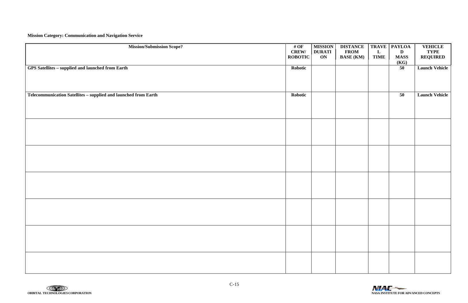
ORBI TEC
ORBITAL TECHNOLOGIES CORPORATION NASA INSTITUTE FOR ADVANCED CONCEPTS
C-15
Mission Category: Communication and Navigation Service
Mission/Submission Scope? # OFCREW/
ROBOTIC
MISSIONDURATI
ON
DISTANCEFROM
BASE (KM)
TRAVEL
TIME
PAYLOAD
MASS(KG)
VEHICLETYPE
REQUIRED
GPS Satellites – supplied and launched from Earth Robotic 50 Launch Vehicle
Telecommunication Satellites – supplied and launched from Earth Robotic 50 Launch Vehicle

ORBI TEC
ORBITAL TECHNOLOGIES CORPORATION NASA INSTITUTE FOR ADVANCED CONCEPTS
C-16

ORBI TEC
ORBITAL TECHNOLOGIES CORPORATION NASA INSTITUTE FOR ADVANCED CONCEPTS
C-17
Mission Category: Surveying/Mapping
Mission/Submission Scope? # OFCREW/
ROBOTIC
MISSIONDURATI
ON
DISTANCEFROM
BASE (KM)
TRAVEL
TIME
PAYLOAD
MASS(KG)
VEHICLETYPE
REQUIRED
Satellites – supplied and launched from Earth
Mapping/Surveying 30 Long-DurationAir Vehicle

ORBI TEC
ORBITAL TECHNOLOGIES CORPORATION NASA INSTITUTE FOR ADVANCED CONCEPTS
C-18

ORBI TEC
ORBITAL TECHNOLOGIES CORPORATION NASA INSTITUTE FOR ADVANCED CONCEPTS
C-19
Mission Category: Personal Transportation
Mission/Submission Scope? # OFCREW/
ROBOTIC
MISSIONDURATI
ON
DISTANCEFROM
BASE (KM)
TRAVEL
TIME
PAYLOAD
MASS(KG)
VEHICLETYPE
REQUIRED
Car/Van Electric/ISRU
1-6 < 1 day 160 km 5 Hours 100 Rover
Bus 40 < 1 day 300 km 6 Hours 100 Bus
All-Terrain vehicle 1-2 < 1 day 50 km 5 Hours 200 Small rover
Motorized sled 1 < 1 day 50 km 1 Hour 50 Rover
Ballistic Vehicle Personal Transport < 1 day 10,000 km Minutes 100 Ballistic

ORBI TEC
ORBITAL TECHNOLOGIES CORPORATION NASA INSTITUTE FOR ADVANCED CONCEPTS
C-20

ORBI TEC
ORBITAL TECHNOLOGIES CORPORATION NASA INSTITUTE FOR ADVANCED CONCEPTS
C-21
Mission Category: Package/Mail Delivery
Mission/Submission Scope? # OFCREW/
ROBOTIC
MISSIONDURATI
ON
DISTANCEFROM
BASE (KM)
TRAVEL
TIME
PAYLOAD
MASS(KG)
VEHICLETYPE
REQUIRED
Cargo delivery Robotic 1 week 10,000 km DAYS 2,000 kg Ground
Emergency Robotic < 1 day VARIED Minutes 10 kg Ballistic
ORBI TEC
ORBITAL TECHNOLOGIES CORPORATION NASA INSTITUTE FOR ADVANCED CONCEPTS
C-22

ORBI TEC
ORBITAL TECHNOLOGIES CORPORATION NASA INSTITUTE FOR ADVANCED CONCEPTS
C-23
Mission Category: Government Activity
Mission/Submission Scope? # OFCREW/
ROBOTIC
MISSIONDURATI
ON
DISTANCEFROM
BASE (KM)
TRAVEL
TIME
PAYLOAD
MASS(KG)
VEHICLETYPE
REQUIRED
Emergency Response (medical supplies, life support) Large Small
66
< 1 day< 1 day
10,0001,000
MinutesMinutes
10010
BallisticBallistic
Law Enforcement (use personal transportation vehicles) Robotic Infinite Infinite NA 50 Ground

ORBI TEC
ORBITAL TECHNOLOGIES CORPORATION NASA INSTITUTE FOR ADVANCED CONCEPTS
C-24
Mission Category: Launch/Space Transport
Mission/Submission Scope? # OFCREW/
ROBOTIC
MISSIONDURATI
ON
DISTANCEFROM
BASE (KM)
TRAVEL
TIME
PAYLOAD
MASS(KG)
VEHICLETYPE
REQUIRED
Orbital vehicle Passenger Cargo
1,0001,000
Launch VehicleLaunch Vehicle

ORBI TEC
ORBITAL TECHNOLOGIES CORPORATION NASA INSTITUTE FOR ADVANCED CONCEPTS
C-25

ORBI TEC
ORBITAL TECHNOLOGIES CORPORATION NASA INSTITUTE FOR ADVANCED CONCEPTS
C-26
Mission Category: Auxiliary Power
Mission/Submission Scope? # OFCREW/
ROBOTIC
MISSIONDURATI
ON
DISTANCEFROM
BASE (KM)
TRAVEL
TIME
PAYLOAD
MASS(KG)
VEHICLETYPE
REQUIRED
Base emergency back-up power.
Portable power source.

ORBI TEC
ORBITAL TECHNOLOGIES CORPORATION NASA INSTITUTE FOR ADVANCED CONCEPTS
C-27

ORBI TEC
ORBITAL TECHNOLOGIES CORPORATION NASA INSTITUTE FOR ADVANCED CONCEPTS
C-28
Mission Category: Life Support
Mission/Submission Scope? # OFCREW/
ROBOTIC
MISSIONDURATI
ON
DISTANCEFROM
BASE (KM)
TRAVEL
TIME
PAYLOAD
MASS(KG)
VEHICLETYPE
REQUIRED
See resource mining transport and cargo transport.Rest of equipment on the base site.No requirement for additional transportation system.

ORBI TEC
ORBITAL TECHNOLOGIES CORPORATION NASA INSTITUTE FOR ADVANCED CONCEPTS
C-29

ORBI TEC
ORBITAL TECHNOLOGIES CORPORATION NASA INSTITUTE FOR ADVANCED CONCEPTS
C-30
Mission Category: Waste/Trash Management
Mission/Submission Scope? # OFCREW/
ROBOTIC
MISSIONDURATI
ON
DISTANCEFROM
BASE (KM)
TRAVEL
TIME
PAYLOAD
MASS(KG)
VEHICLETYPE
REQUIRED
Reprocess on site or shipped via cargo transport
High-level nuclear waste transport (Iron Ore transport)
2 10,000+ km Ground

ORBI TEC
ORBITAL TECHNOLOGIES CORPORATION NASA INSTITUTE FOR ADVANCED CONCEPTS
C-31
ORBI TEC
ORBITAL TECHNOLOGIES CORPORATION NASA INSTITUTE FOR ADVANCED CONCEPTS
C-32
Mission Category: Health Care/Maintenance
Mission/Submission Scope? # OFCREW/
ROBOTIC
MISSIONDURATI
ON
DISTANCEFROM
BASE (KM)
TRAVEL
TIME
PAYLOAD
MASS(KG)
VEHICLETYPE
REQUIRED
No additional transport required.

ORBI TEC
ORBITAL TECHNOLOGIES CORPORATION NASA INSTITUTE FOR ADVANCED CONCEPTS
C-33

ORBI TEC
ORBITAL TECHNOLOGIES CORPORATION NASA INSTITUTE FOR ADVANCED CONCEPTS
C-34
Mission Category: Virtual Travel Market
Mission/Submission Scope? # OFCREW/
ROBOTIC
MISSIONDURATI
ON
DISTANCEFROM
BASE (KM)
TRAVEL
TIME
PAYLOAD
MASS(KG)
VEHICLETYPE
REQUIRED
No additional transport required. Use existing rover to mount video/control system.

ORBI TEC
ORBITAL TECHNOLOGIES CORPORATION NASA INSTITUTE FOR ADVANCED CONCEPTS
C-35