final sampling port design addendum 08-2013 · shallow foundations bearing capacity and settlement....
TRANSCRIPT

ONONDAGA LAKE CAPPING, DREDGING, HABITAT AND PROFUNDAL ZONE (SMU 8) FINAL DESIGN
CAP SAMPLING PORT ADDENDUM
Prepared for:
301 Plainfield Road, Suite 330
Syracuse, NY 13212
Prepared by:
PARSONS
301 Plainfield Road, Suite 350 Syracuse, NY 13212
290 Elwood Davis Road, Suite 318
Liverpool, NY 13088
AUGUST 2013
ONONDAGA LAKE CAPPING, DREDGING , HABITAT ANDPROFUNDAL ZONE (SMU 8) FINAL DESIGN
CAP SAMPLING PORT ADDENDUM
PARSONS
P:\Honeywell -SYR\446232 - Cap Design\09 Reports\9.3 Final Design Report\Sampling Port Addendum\Final Sampling Port Addendum\August 2013 Final Version\Final Sampling PORT DESIGN ADDENDUM 08-2013.DOCX
August 2013 1
As detailed in the Final Design, the Onondaga Lake sediment cap has been designed to provide a high level of long-term protection and to be resistant to disruption by forces such as wind-generated waves. Post-construction monitoring of the capped areas will be performed to verify that the overall integrity of the cap is maintained so that it remains physically stable (i.e., does not erode) and chemically protective over time. This will include both physical and chemical monitoring.
Chemical monitoring will involve collection of samples for measuring chemical concentrations within the habitat and chemical isolation layers to verify that contaminants are not moving through the cap at rates and concentrations that exceed specified remedy success metrics. Details of the chemical monitoring methods, frequencies, locations, sampling intervals, procedures, and response actions are provided in the Onondaga Lake Monitoring and Maintenance Scoping (OLMMS) Document.
In some shallow water portions of the cap, the habitat/erosion protection substrate overlying the chemical isolation layer consists of fine or coarse gravel or gravelly-cobble. Solid phase and porewater sampling methods in these areas will be evaluated in the field in 2013 following placement of these cap materials in representative areas. It is anticipated that porewater peepers can be advanced through this material to allow porewater collection from the habitat and chemical isolation layers. However, these substrates are likely too coarse to allow collection of cores for chemical analysis. In addition, the coarse gravel and gravelly-cobble may be too coarse to allow collection of a representative core sample from the underlying chemical isolation layer. Because the ability to sample in these areas has not been verified, sampling “ports” will be installed in initial capping areas where these substrates are present.
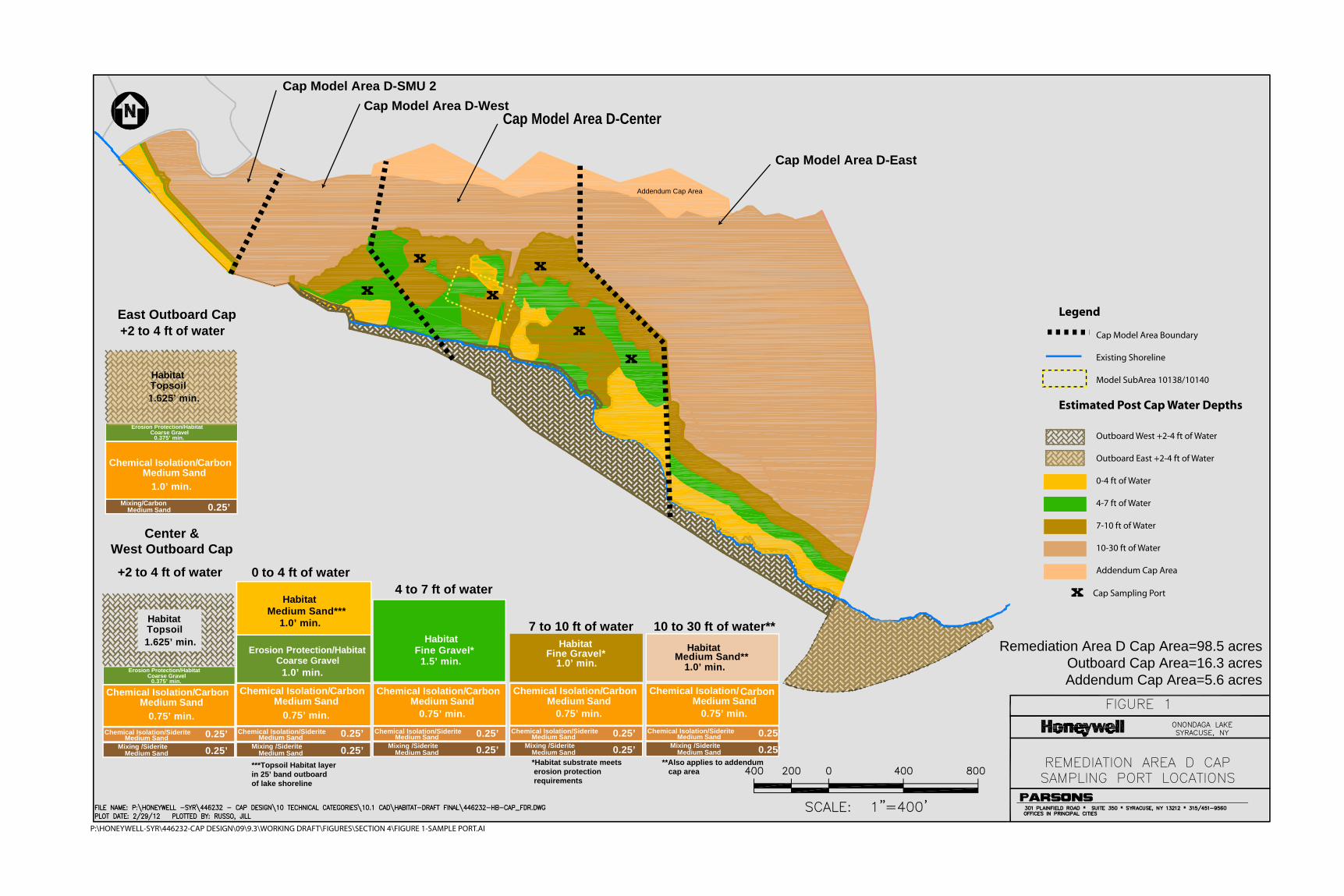
Planned sampling port locations in Remediation Area D, most of which is anticipated to be capped by the end of 2013, are shown in Figure 1. These sampling port locations were selected based on the presence of coarse substrate in the habitat/erosion protection layer. Coarse substrate is also present in the area adjacent to the DOT turnaround area that was capped in 2012. However, no sampling ports are located in this area due to potential concerns that they could present a navigational hazard in this area, which is the site of an anticipated future boat launch. The dredging depth in this area will result in the removal of the vast majority of contaminated sediment inventory, therefore cap chemical performance in this area is not a significant concern. Capping will also be completed in the deeper portions of Remediation Area E in 2013. However, none of these areas include coarse substrate where sampling may be impacted, therefore, no sampling ports are included in this portion of Remediation Area E.
Following completion of the sampling method evaluation, the need for sampling ports in other cap areas, including the remaining areas to be capped in Remediation Area E, will be reassessed. Depending on the timing of the field sampling methods evaluation and the progression of capping, some of the sampling port locations shown on Figure 1 may not be required, subject to review and approval by New York State Department of Environmental Conservation (NYSDEC).

ONONDAGA LAKE CAPPING, DREDGING , HABITAT ANDPROFUNDAL ZONE (SMU 8) FINAL DESIGN
CAP SAMPLING PORT ADDENDUM
PARSONS
P:\Honeywell -SYR\446232 - Cap Design\09 Reports\9.3 Final Design Report\Sampling Port Addendum\Final Sampling Port Addendum\August 2013 Final Version\Final Sampling PORT DESIGN ADDENDUM 08-2013.DOCX
August 2013 2
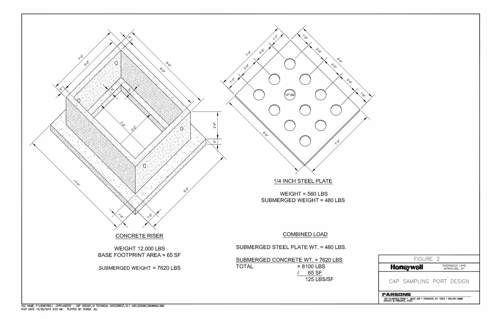
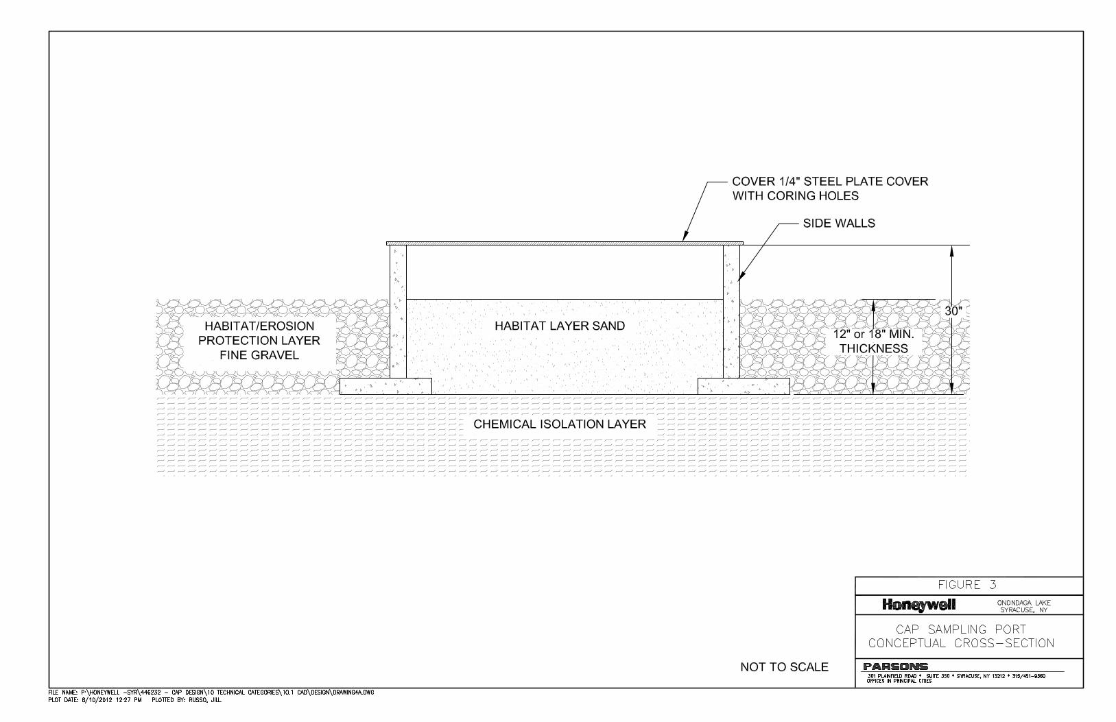
The sampling ports will consist of concrete manhole-type riser sections that will be placed on top of the chemical isolation layer and filled with a finer-grained material (sand) in lieu of the larger armor stone surrounding it (Figures 2 and 3). This finer-grained material will allow collection of core and porewater samples within the habitat/erosion protection and chemical isolation layers from within the sampling port. The sampling ports will include a steel cover to minimize the erosive forces on the sand within the sampling port. Holes within the cover will allow collection of cores and porewater samples from within the ports without removing the cover.
To verify that the bearing capacity of the underlying sediment is not exceeded by the loading associated with the sampling port, a bearing capacity analysis was completed and is included in Appendix A.
ONONDAGA LAKE CAPPING, DREDGING , HABITAT ANDPROFUNDAL ZONE (SMU 8) FINAL DESIGN
CAP SAMPLING PORT ADDENDUM
PARSONS
P:\Honeywell -SYR\446232 - Cap Design\09 Reports\9.3 Final Design Report\Sampling Port Addendum\Final Sampling Port Addendum\August 2013 Final Version\Final Sampling PORT DESIGN ADDENDUM 08-2013.DOCX
August 2013
FIGURES
Legend
Cap Model Area Boundary
Existing Shoreline Model SubArea 10138/10140
Estimated Post Cap Water Depths
Outboard West +2-4 ft of Water
Outboard East +2-4 ft of Water
0-4 ft of Water
4-7 ft of Water
7-10 ft of Water
10-30 ft of Water
Addendum Cap Area
Cap Sampling Port
X
P:\HONEYWELL-SYR\446232-CAP DESIGN\09\9.3\WORKING DRAFT\FIGURES\SECTION 4\FIGURE 1-SAMPLE PORT.AI
X
X
XX
X
X
Addendum Cap Area
*Habitat substrate meets erosion protection requirements
4 to 7 ft of water
Habitat
1.5’ min.Fine Gravel*
10 to 30 ft of water**Habitat
1.0’ min.Medium Sand**
7 to 10 ft of waterHabitat
1.0’ min.Fine Gravel*
**Also applies to addendum cap area
Chemical Isolation/ Carbon Medium Sand
0.75’ min. Chemical Isolation/Siderite
Medium SandMixing /Siderite 0.25’ Medium Sand
Chemical Isolation/ Carbon Medium Sand
0.75’ min. Chemical Isolation/Siderite
Medium SandMixing /Siderite 0.25’ Medium Sand
Chemical Isolation/ Carbon Medium Sand
0.75’ min. Chemical Isolation/Siderite
Medium SandMixing /Siderite 0.25’ Medium Sand
0.25’ 0.25’ 0.25’
+2 to 4 ft of water
Center &West Outboard Cap
0.25’
East Outboard Cap
Chemical Isolation/ Carbon Medium Sand
Chemical Isolation/Siderite Medium Sand
Mixing /Siderite
0.75’ min.
0.25’ Medium Sand
0.25’
Erosion Protection/Habitat Coarse Gravel
0.375’ min.
0 to 4 ft of water
Chemical Isolation/ Carbon Medium Sand
Chemical Isolation/Siderite Medium Sand
Mixing /Siderite
0.75’ min.
0.25’ Medium Sand
0.25’
Erosion Protection/Habitat Coarse Gravel
Habitat Medium Sand***
1.0’ min.
1.0’ min.
***Topsoil Habitat layer in 25’ band outboardof lake shoreline
+2 to 4 ft of water
Chemical Isolation/ Carbon Medium Sand
Mixing/Carbon
1.0’ min.
0.25’ Medium Sand
Remediation Area D Cap Area=98.5 acresOutboard Cap Area=16.3 acresAddendum Cap Area=5.6 acres
Cap Model Area D-SMU 2Cap Model Area D-West
Cap Model Area D-Center
Cap Model Area D-East
Erosion Protection/Habitat Coarse Gravel
0.375’ min.
Habitat Topsoil1.625’ min.
E i P t ti /H bit t
Habitat Topsoil1.625’ min.
ONONDAGA LAKE CAPPING, DREDGING , HABITAT ANDPROFUNDAL ZONE (SMU 8) FINAL DESIGN
CAP SAMPLING PORT ADDENDUM
PARSONS
P:\Honeywell -SYR\446232 - Cap Design\09 Reports\9.3 Final Design Report\Sampling Port Addendum\Final Sampling Port Addendum\August 2013 Final Version\Final Sampling PORT DESIGN ADDENDUM 08-2013.DOCX
August 2013
APPENDIX A BEARING CAPACITY ANALYSIS

CALCULATION COVER SHEET
PROJECT: Onondaga Lake CALC NO. 1 SHEET 1 of 5
SUBJECT: Attachment X – Cap Sampling Port Bearing Capacity Analysis – Example Calculation
Objective: To determine the factor of safety relative to bearing capacity for the placement of the cap sampling port.
References:
Das, B.M. 1999. Shallow Foundations Bearing Capacity and Settlement. CRC Press.
Das, B.M. 1990. Principles of Geotechnical Engineering. Second Edition. PWS-Kent Publishing Company.
Determination of Bearing Loads Due to cap Sampling Port Structure: The following presents a detailed summary
and example calculation for determining the factor of safety relative to bearing capacity for the placement of a concrete
cap sampling port structure on sediment caps in Onondaga Lake. The calculation was performed by assuming the
sampling port structure is similar to a shallow foundation that rests on a layered material (the sand and gravel cap over
the native sediments in Onondaga Lake). The Terzaghi-Meyerhof method was used to compute the general bearing
capacity of the cap and underlying sediments to support the cap sampling port.
Sediment Cap Properties:
The sediment cap (i.e. top layer) was conservatively assumed to be comprised of sand only (no overlying armor layer,
which would provide for a higher bearing capacity) with the following soil properties:
Cohesion (c) = 0 pounds per square foot (psf)
Soil friction angle () = 32 degrees
Unit weight () = 120 pounds per cubic foot (pcf) for sand
Submerged unit weight (’) = 120 pcf for sand – 62.4 pcf for water = 57.6 pcf
Thickness of the sediment cap layer (H) = 1.25 feet (15 inches)
The Bearing Capacity Factors for the cap (general shear failure) are:
Nc = 35.49 (from Table 10.1 of Das 1990)
Nq = 23.18 (from Table 10.1 of Das 1990)
N = 30.21 (from Table 10.1 of Das 1990)
Cap Sampling Port Properties:
The cap sampling port has been analyzed for placement below the water surface. The following properties for
width (B), length (L), height (h), footprint area (A), and weight (Q) have been provided by Parsons (a detail of the cap
sampling port is attached):
B= 9.17 feet
L = 11 feet
A= 64 square feet
Q = 12,556 pounds (above water bearing elevation)
Unit weight () = 150 pcf for concrete
Submerged unit weight (’) = 150 pcf for concrete – 62.4 pcf for water = 87.6 pcf or (60% of the above water unit
weight)
Based on the percentage reduction in weight of concrete in the submerged condition (60% of Unit weight ()), a similar
reduction has also been used to estimate the submerged weight of the structure.
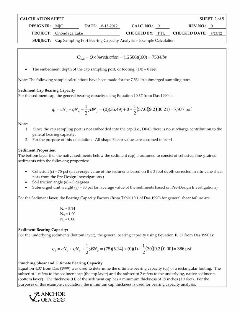
CALCULATION SHEET SHEET 2 of 5
DESIGNER: MJC DATE: 8-15-2012 CALC. NO.: 0 REV.NO.: 0
PROJECT: Onondaga Lake CHECKED BY: PTL CHECKED DATE: 8/23/12
SUBJECT: Cap Sampling Port Bearing Capacity Analysis – Example Calculation
lbsreductionQQsub 7534)60)(.12566(%
The embedment depth of the cap sampling port, or footing, (Df) = 0 feet
Note: The following sample calculations have been made for the 7,534 lb submerged sampling port.
Sediment Cap Bearing Capacity
For the sediment cap, the general bearing capacity using Equation 10.37 from Das 1990 is:
psf 977,721.302.96.572
10)49.35)(0(
2
11 BNqNcNq qc
Note:
1. Since the cap sampling port is not embedded into the cap (i.e., Df=0) there is no surcharge contribution to the
general bearing capacity.
2. For the purpose of this calculation - All shape Factor values are assumed to be =1.
Sediment Properties:
The bottom layer (i.e. the native sediments below the sediment cap) is assumed to consist of cohesive, fine-grained
sediments with the following properties:
Cohesion (c) = 75 psf (an average value of the sediments based on the 3 foot depth corrected in situ vane shear
tests from the Pre-Design Investigations )
Soil friction angle () = 0 degrees
Submerged unit weight () = 30 pcf (an average value of the sediments based on Pre-Design Investigations)
For the Sediment layer, the Bearing Capacity Factors (from Table 10.1 of Das 1990) for general shear failure are:
Nc = 5.14
Nq = 1.00
N = 0.00
Sediment Bearing Capacity:
For the underlying sediments (bottom layer), the general bearing capacity using Equation 10.37 from Das 1990 is:
psf 38600.02.9302
1)1)(0()14.5)(75(
2
12 BNqNcNq qc
Punching Shear and Ultimate Bearing Capacity
Equation 4.37 from Das (1999) was used to determine the ultimate bearing capacity (qu) of a rectangular footing. The
subscript 1 refers to the sediment cap (the top layer) and the subscript 2 refers to the underlying, native sediments
(bottom layer). The thickness (H) of the sediment cap has a minimum thickness of 15 inches (1.3 feet). For the
purposes of this example calculation, the minimum cap thickness is used for bearing capacity analysis.
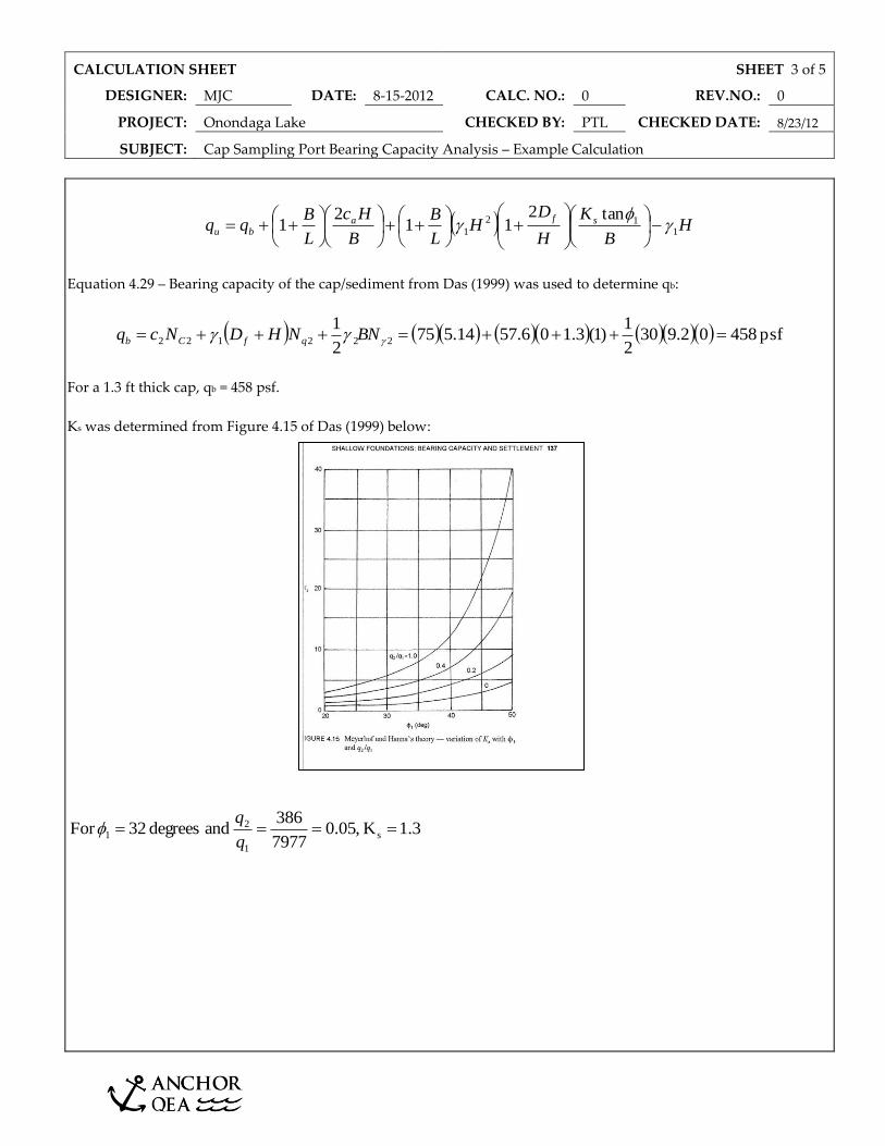
CALCULATION SHEET SHEET 3 of 5
DESIGNER: MJC DATE: 8-15-2012 CALC. NO.: 0 REV.NO.: 0
PROJECT: Onondaga Lake CHECKED BY: PTL CHECKED DATE: 8/23/12
SUBJECT: Cap Sampling Port Bearing Capacity Analysis – Example Calculation
HB
K
H
DH
L
B
B
Hc
L
Bqq sfa
bu 112
1
tan211
21
Equation 4.29 – Bearing capacity of the cap/sediment from Das (1999) was used to determine qb:
psf 45802.9302
1)1(3.106.5714.575
2
1222122 BNNHDNcq qfCb
For a 1.3 ft thick cap, qb = 458 psf.
Ks was determined from Figure 4.15 of Das (1999) below:
3.1K ,05.07977
386 and degrees 32For s
1
21
q
q
CALCULATION SHEET SHEET 4 of 5
DESIGNER: MJC DATE: 8-15-2012 CALC. NO.: 0 REV.NO.: 0
PROJECT: Onondaga Lake CHECKED BY: PTL CHECKED DATE: 8/23/12
SUBJECT: Cap Sampling Port Bearing Capacity Analysis – Example Calculation
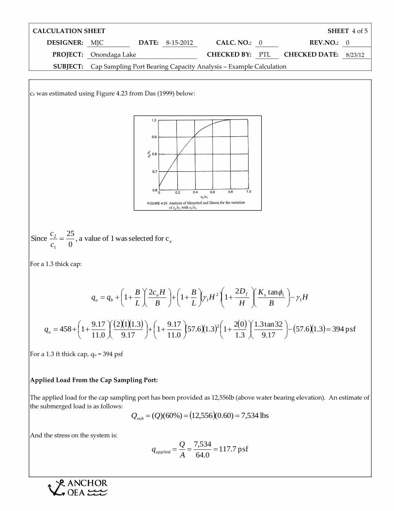
ca was estimated using Figure 4.23 from Das (1999) below:
a
1
2 cfor selected was1 of valuea ,0
25 Since c
c
For a 1.3 thick cap:
HB
K
H
DH
L
B
B
Hc
L
Bqq sfa
bu 112
1
tan211
21
psf 3943.16.57
17.9
32tan3.1
3.1
0213.16.57
0.11
17.91
17.9
3.112
0.11
17.91458
2
uq
For a 1.3 ft thick cap, qu = 394 psf
Applied Load From the Cap Sampling Port:
The applied load for the cap sampling port has been provided as 12,556lb (above water bearing elevation). An estimate of
the submerged load is as follows:
lbs 534,7)60.0(556,12%)60)(( QQsub
And the stress on the system is:
psf 7.1170.64
534,7
A
Qqapplied

CALCULATION SHEET SHEET 5 of 5
DESIGNER: MJC DATE: 8-15-2012 CALC. NO.: 0 REV.NO.: 0
PROJECT: Onondaga Lake CHECKED BY: PTL CHECKED DATE: 8/23/12
SUBJECT: Cap Sampling Port Bearing Capacity Analysis – Example Calculation
Factor of Safety:
Therefore, the Factors of Safety (FOS) for the 1.3 thick cap is:
35.3117.7
394 FOS capft thick -1.3
applied
u
q
q
A factor FOS of 3 is typically considered acceptable for punching shear failure. Therefore, with a FOS of 3.35, the case
analyzed above is considered stable.
RECORD OF REVISIONS
NO. REASON FOR REVISION BY CHECKED APPROVED/ ACCEPTED
DATE