final seminar report
TRANSCRIPT
SUBMITTED BY : Pankaj Kunjwal ROLL NO. : 100070520648 BRANCH :
Electrical Engineering COLLEGE : BHSBIET

INTRODUCTIONy Power Station (also referred to as
generating station or power plant) is anindustrial facility for the generation ofelectric power.
y Power plant is also used to refer to theengine in ships, aircraft and other largevehicles. Some prefer to use the termenergy center because it moreaccurately describes what the plantsdo, which is the conversion of otherforms of energy, like chemicalenergy, gravitational potential energyor heat energy into electrical energy.
y Power station and power plant are bothwidely used, power station prevailing inmany Commonwealth countries andespecially in the United Kingdom

POWER GENERATION IN INDIAy NTPC s core business is engineering, construction
and operation of power generating plants.
y Consultant in the power plant constructions andpower generation to companies in India andabroad.
y Installed capacity of NTPC is 27,904 MW throughits 15 coal based (22,895 MW), 7 gas based (3,955MW) & 4 Joint Venture Projects (1,054 MW).

Overall Power Generation
Unit
Installed Capacity
Generation
No. of employees
Generation/employee
MW
MUs
No.
MUs
1997-98
16,847
97,609
23,585
4.14
2006-07
26,350
1,88,674
24,375
7.74
% of increase
56.40
93.29
3.34
86.95
OPERATIONAL PERFORMANCE OF COAL BASED NTPC STATIONS
Unit 97- 98-99
98
99-00 00-01 01-02 02-03 03-04 04-05 05-06 06-07
Generation BU 106. 109.5
2
118.7 130.1 133.2 140.86 149.16 159.11 170.88 188.67
PLF % 75.2 76.60
0
80.39 81.8 81.1 83.6 84.4 87.51 87.54 89.43
Availability
Factor
% 85.0 89.36
3
90.06 88.54 81.8 88.7 88.8 91.20 89.91 90.09

ABOUT NTPCy NTPC Limited is the largest
thermal power generatingcompany of India.
y It was incorporated in the year1975 to accelerate powerdevelopment in the country as awholly owned company of theGovernment of India.
y At present, Government of Indiaholds 89.5% of the total equityshares of the company .
y NTPC has emerged as a trulynational power company, withpower generating facilities in allthe major regions of the country.

COAL BASED(Owned by NTPC) STATECOMMISSIONEDCAPACITY(MW)
1. Singrauli Uttar Pradesh 2,000
2. Korba Chhattisgarh 2,600
3. Ramagundam Andhra Pradesh 2,600
4. Farakka West Bengal 2,100
5. Vindhyachal Madhya Pradesh 3,760
6. Rihand Uttar Pradesh 2,500
7. Kahalgaon Bihar 2,340
8. Dadri Uttar Pradesh 1,820
9. Talcher Kaniha Orissa 3,000
10. Feroze Gandhi, Unchahar Uttar Pradesh 1,050
11. Talcher Thermal Orissa 460
12. Simhadri Andhra Pradesh 2,000
13. Tanda Uttar Pradesh 440
14. Badarpur Delhi 705
15. Sipat Chhattisgarh 2,980
16. Mauda Maharashta 500
Total 30,855
With 16 coal based power stations, NTPC is the largest thermal power generating company in the country. The company has a coal based installed capacity of 30,855 MW.

Turnaround Capabilty
NTPC has played an extremely important role in turning around sub-optimally performing stations. The phenomenal improvement in the performance of Badarpur, Unchahar, Talcher and Tanda by NTPC make them our big success stories.
The expertise in R&M and performance turnaround was developed and built up by NTPC with the operational turnaround of Badarpur TPS through scientifically engineered R&M initiatives. The PLF of the power station improved from 31.94% at the time of the takeover to 86.46% for the year 2007-08.
Badarpur (705 MW)

The Feroze Gandhi Unchahar Power Station was taken over by NTPC whereby the cash strapped UPSEB was rescued by the turnaround expertise of NTPC.The remarkable speed and extent of the turnaround achieved can be seen in the table.
Unchahar (420 MW)

An even more challenging turnaround story was being scripted at the OSEB's old power plant at Talcher. Taken over in June 1995, the table indicates the dramatic gains in the performance of the power plant as a result of NTPC’s expertise.
Talcher (460 MW)
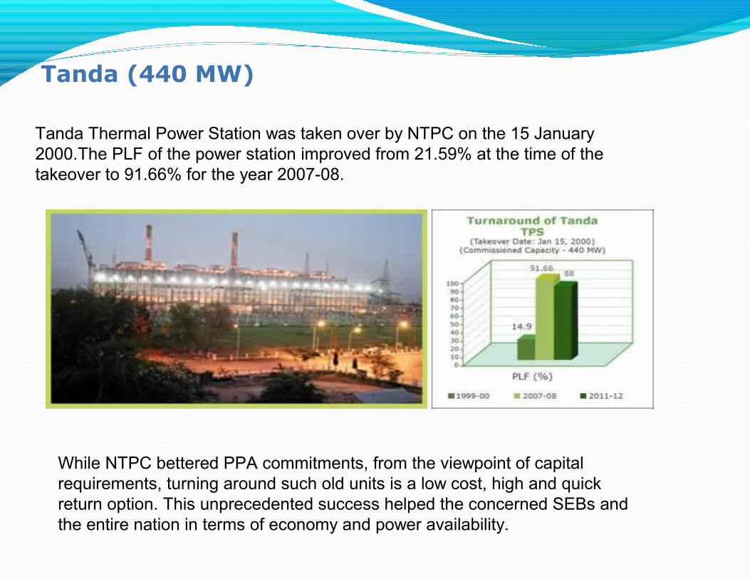
Tanda Thermal Power Station was taken over by NTPC on the 15 January 2000.The PLF of the power station improved from 21.59% at the time of the takeover to 91.66% for the year 2007-08.
Tanda (440 MW)
While NTPC bettered PPA commitments, from the viewpoint of capital requirements, turning around such old units is a low cost, high and quick return option. This unprecedented success helped the concerned SEBs and the entire nation in terms of economy and power availability.

NTPC Environment Policy andEnvironment Management Systemy Environment Management, Occupational Health
and Safety Systems
y Pollution Control systems
y Cooling Tower
y Liquid Waste Treatment Plants & ManagementSystem
y Sewage Treatment Plants & Facilities

INTRODUCTION TO THERMAL POWER PLANT•A thermal power station is a power plant in which the prime mover is steam driven. Water is heated, turns into steam and spins a steam turbine which drives an electrical generator.
•After it passes through the turbine, the steam is condensed in a condenser and recycled to where it was heated; this is known as a Rankine cycle.
•The greatest variation in the design of thermal power stations is due to the different fuel sources
•Electric power plants typically use three-phase electrical generators to produce alternating current (AC) electric power at a frequency of 50 Hz or 60 Hz

FUNCTIONING

FUNTIONING OF BADARPUR PLANT(Introduction)Coal supply Coal pulverizerBoilerPrecipitators and stack Turbine and generatorCondensers and cooling
water systemWater purificationAsh systemstransformer and
transmission lines

1. Cooling tower 10. Steam governor valve 19. Superheater
2. Cooling water pump 11. High pressure turbine 20. Forced draught fan
3. Transmission line (3-phase) 12. Deaerator 21. Reheater
4. Unit transformer (3-phase) 13. Feed heater 22. Air intake
5. Electric generator (3-phase) 14. Coal conveyor 23. Economizer
6. Low pressure turbine 15. Coal hopper 24. Air preheater
7. Boiler feed pump 16. Pulverized fuel mill 25. Precipitator
8. Condenser 17. Boiler drum 26. Induced draught fan
9. Intermediate pressure turbine
18. Ash hopper 27. Chimney Stack

STEAM GENERATOR OR BOILERBoiler is a rectangular furnace about 50ft on a side and 130ft tall which produces steam at high purity. Pressure and temprature required for the steam turbine that drives the electrical generator.Pulverized coal is air-blown into the furnace from fuel nozzels and it rapidly burns ,forming a large fireball at the center. As the water in the boiler circulates it absorbs heat and changes into steam at 700F (370C) and 3,200psi(22.1MPa).The steam is then superheated to 1000f(540C) tp prepare it for the turbine.The air and flue gas path eqipment include Forced draft fanAir preheatedBoiler furnace Induced draft fanFly ash collectorsFlue gas stack

STEAM TURBINE
Steam turbines are used in all of our major coal fired power stations to drive the generators ,which produce electricity.The turbine normaly consists of several stages with each stage consisitng of stationary blade and a rotating balde.Stationary blades convert the potential energy of the steam to kinetic energy .The rotating blades convert the kinetic energy into forces ,caused by pressure drop ,which results in the rotation of the turbine shaft.In badarpur plant (large power stations),the steam turbines are split int0three separate stages a.High pressure b.Intermediate pressurec.Low pressure the rotational speed is 3000 RPM for indian system (50hz).

TURBINE OPERATION

A 210MW TURBINE GENERATOR ATBADARPUR THERMAL POWER STATION
NEW DELHI
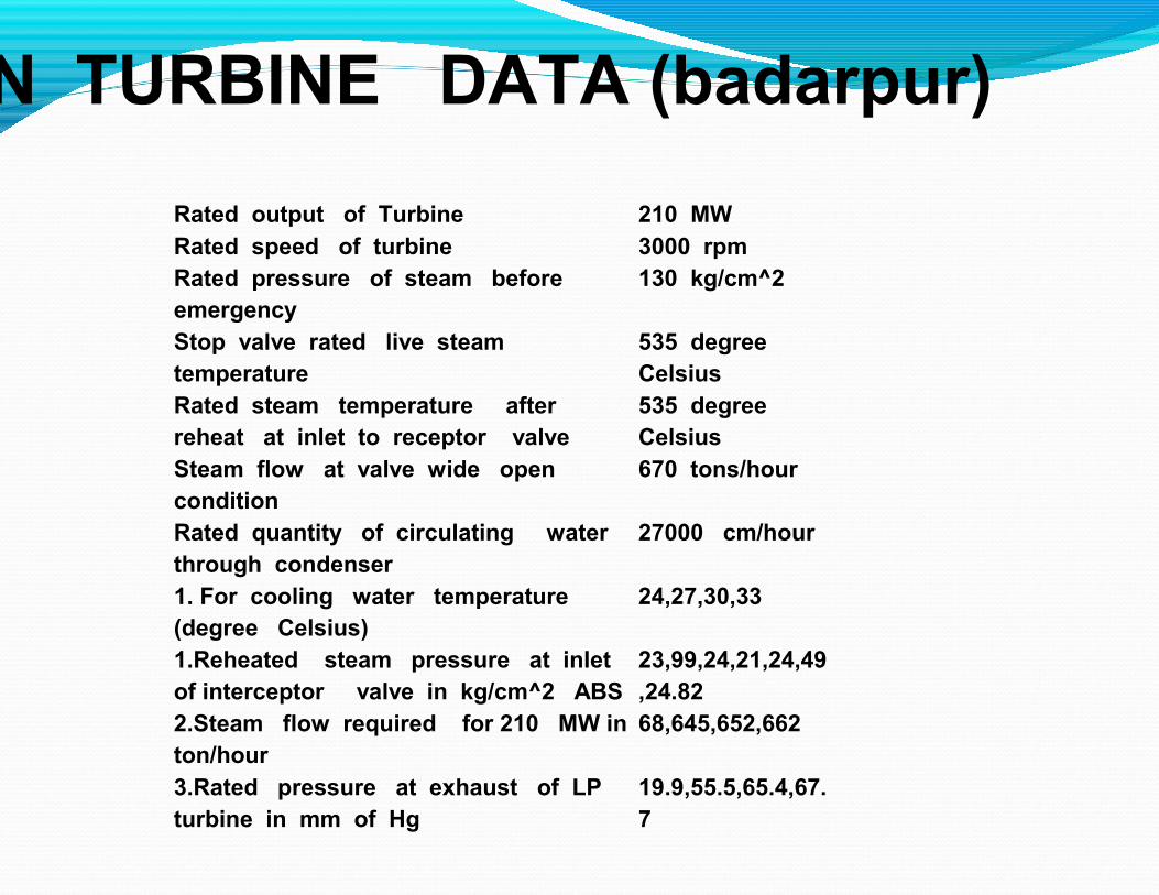
MAIN TURBINE DATA (badarpur)
Rated output of TurbineRated speed of turbineRated pressure of steam beforeemergencyStop valve rated live steamtemperatureRated steam temperature afterreheat at inlet to receptor valveSteam flow at valve wide openconditionRated quantity of circulating waterthrough condenser1. For cooling water temperature(degree Celsius)1.Reheated steam pressure at inletof interceptor valve in kg/cm^2 ABS2.Steam flow required for 210 MW inton/hour3.Rated pressure at exhaust of LPturbine in mm of Hg
210 MW3000 rpm130 kg/cm^2
535 degreeCelsius535 degreeCelsius670 tons/hour
27000 cm/hour
24,27,30,33
23,99,24,21,24,49,24.8268,645,652,662
19.9,55.5,65.4,67.7
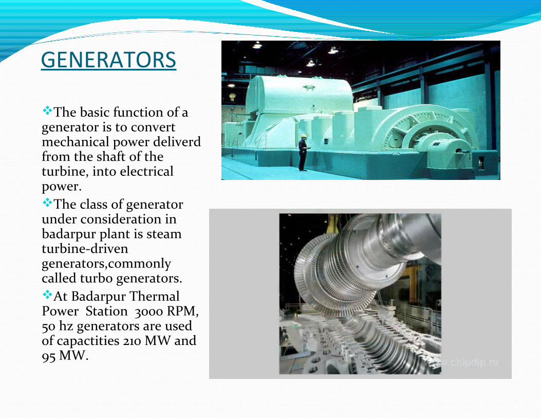
GENERATORS
The basic function of a generator is to convert mechanical power deliverd from the shaft of the turbine, into electrical power.The class of generator under consideration in badarpur plant is steam turbine-driven generators,commonly called turbo generators.At Badarpur Thermal Power Station 3000 RPM, 50 hz generators are used of capactities 210 MW and 95 MW.
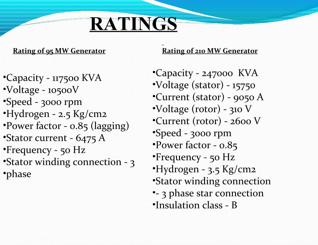
•Capacity - 117500 KVA•Voltage - 10500V•Speed - 3000 rpm•Hydrogen - 2.5 Kg/cm2•Power factor - 0.85 (lagging)•Stator current - 6475 A•Frequency - 50 Hz•Stator winding connection - 3•phase
Rating of 95 MW Generator
•Capacity - 247000 KVA•Voltage (stator) - 15750 •Current (stator) - 9050 A•Voltage (rotor) - 310 V•Current (rotor) - 2600 V•Speed - 3000 rpm•Power factor - 0.85•Frequency - 50 Hz•Hydrogen - 3.5 Kg/cm2•Stator winding connection•- 3 phase star connection•Insulation class - B
Rating of 210 MW Generator
RATINGS
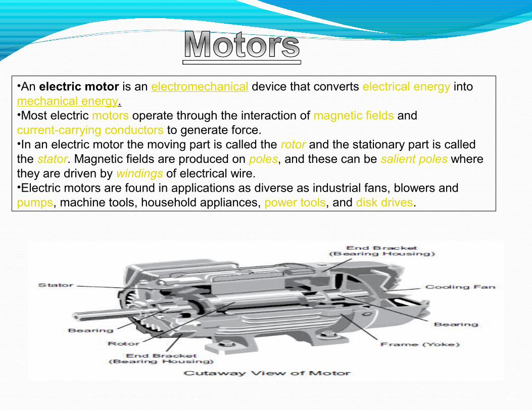
•An electric motor is an electromechanical device that converts electrical energy into mechanical energy.•Most electric motors operate through the interaction of magnetic fields and current-carrying conductors to generate force.•In an electric motor the moving part is called the rotor and the stationary part is called the stator. Magnetic fields are produced on poles, and these can be salient poles where they are driven by windings of electrical wire. •Electric motors are found in applications as diverse as industrial fans, blowers and pumps, machine tools, household appliances, power tools, and disk drives.
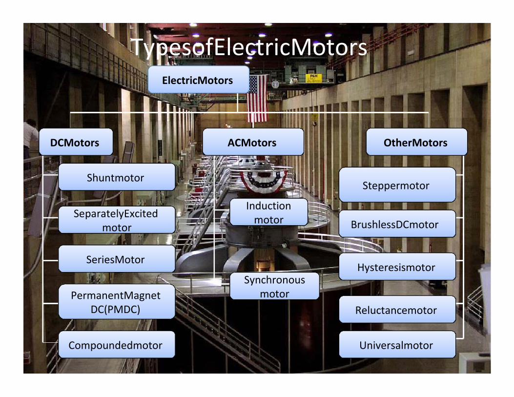
TypesofElectricMotorsElectricMotors
DCMotors
Shuntmotor
SeparatelyExcitedmotor
SeriesMotor
PermanentMagnetDC(PMDC)
Compoundedmotor
ACMotors OtherMotors
Steppermotor
Inductionmotor BrushlessDCmotor
HysteresismotorSynchronous
motorReluctancemotor
Universalmotor
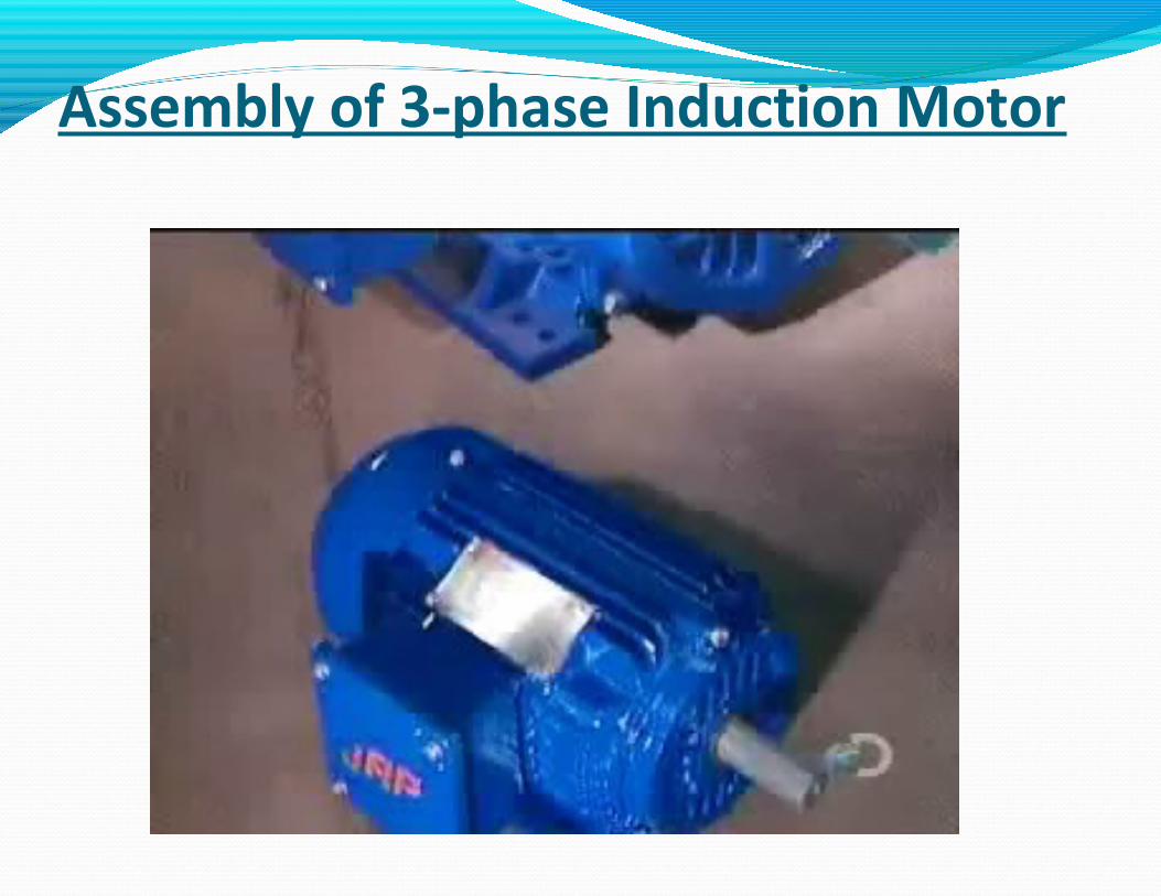
Assembly of 3-phase Induction Motor

Construction Of 3-phase AC Induction Motor
Three-phase AC induction motors are commonly used in industrial applications. This type of motor has three main parts, rotor, stator, and enclosure. The stator and rotor do the work, and the enclosure protects the stator and rotor.
Stator Core:- The stator is the stationary part of the motor’s electromagnetic circuit. The stator core is made up of many thin metal sheets, called laminations. Laminations are used to reduce energy loses that would result if a solid core were used. Generally choice of material is steel to keep down hysteresis losses.

Stator Windings:- Stator laminations are stacked together forming a hollow cylinder. Coils of insulated wire are inserted into slots of the stator core.When the assembled motor is in operation, the stator windings are connected directly to the power source. Each grouping of coils, together with the steel core it surrounds, becomes an electromagnet when current is applied.
Rotor Construction:- The rotor is the rotating part of the motor’s electromagnetic circuit. The most common type of rotor used in a three-phase induction motor is a squirrel cage rotor. Other types of rotor construction is discussed later in the course. The squirrel cage rotor is so called because its construction is reminiscent of therotating exercise wheels found in some pet cages.

ENCLOSURE The enclosure consists of a frame (or yoke) and two end brackets (or bearing housings). The stator is mounted inside the frame. The rotor fits inside the stator with a slight air gap separating it from the stator. There is no direct physical connection between the rotor and the stator.

Layout of C.H.P.

Coal handling division of Badarpurplant
y Coal handling plant catersto the need of units
coal to unitsy whereas the latter supplies
y C.H.P. supplies coal tosecond and third stages inthe advent coal to usableform (crushed)
where it is send to furnace.y Send it to bunkers, from

NEW COAL HANDLING PLANT(N.C.H.P)

Major Components
1. Wagon Tippler: -a. Wagons from the coal yard come to thetippler and are emptied here. The process is performed by a slip ringmotor of rating: 55 KW, 415V, 1480 RPM.
b.This motor turns the wagon by 135 degrees and coal falls directly onthe conveyor through vibrators.
2.Conveyor: - a. There are 14 conveyors in the plant. They arenumbered so that their function can be easily demarcated.
b.Conveyors are made of rubber and more with a speed of 250-300m/min. Motors employed for conveyors has a capacity of 150 HP.
3.Zero Speed Switch:-It is safety device for motors, i.e., if belt isnot moving or may burn.
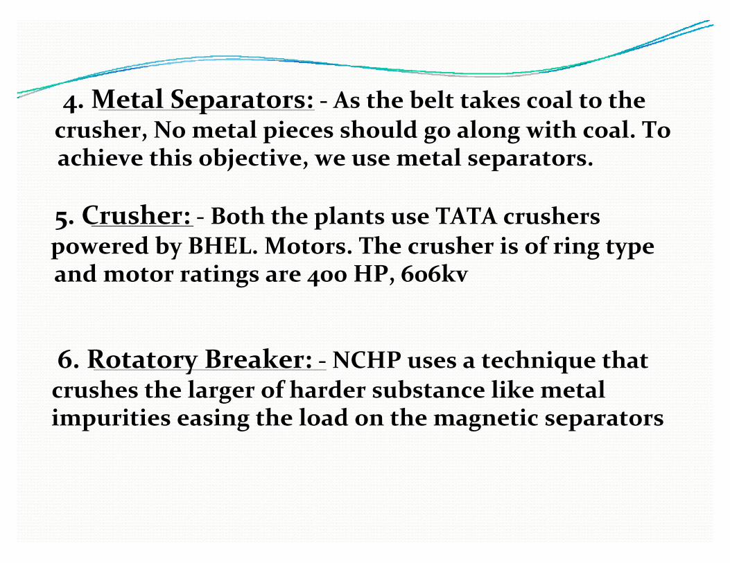
4. Metal Separators: - As the belt takes coal to thecrusher, No metal pieces should go along with coal. Toachieve this objective, we use metal separators.
5. Crusher: - Both the plants use TATA crusherspowered by BHEL. Motors. The crusher is of ring typeand motor ratings are 400 HP, 606kv
6. Rotatory Breaker: - NCHP uses a technique thatcrushes the larger of harder substance like metalimpurities easing the load on the magnetic separators

•In an electric power system, switchgear is the combination of electrical disconnect switches, fuses or circuit breakers used to control, protect and isolate electrical equipment. •Switchgear is used both to de-energize equipment to allow work to be done to clear faults downstream. •High voltage switchgear was invented at the end of the 19th century for operating motors and other electric machines.
•The technology has been improved over time and can be used with voltages up to 1,100 kV.
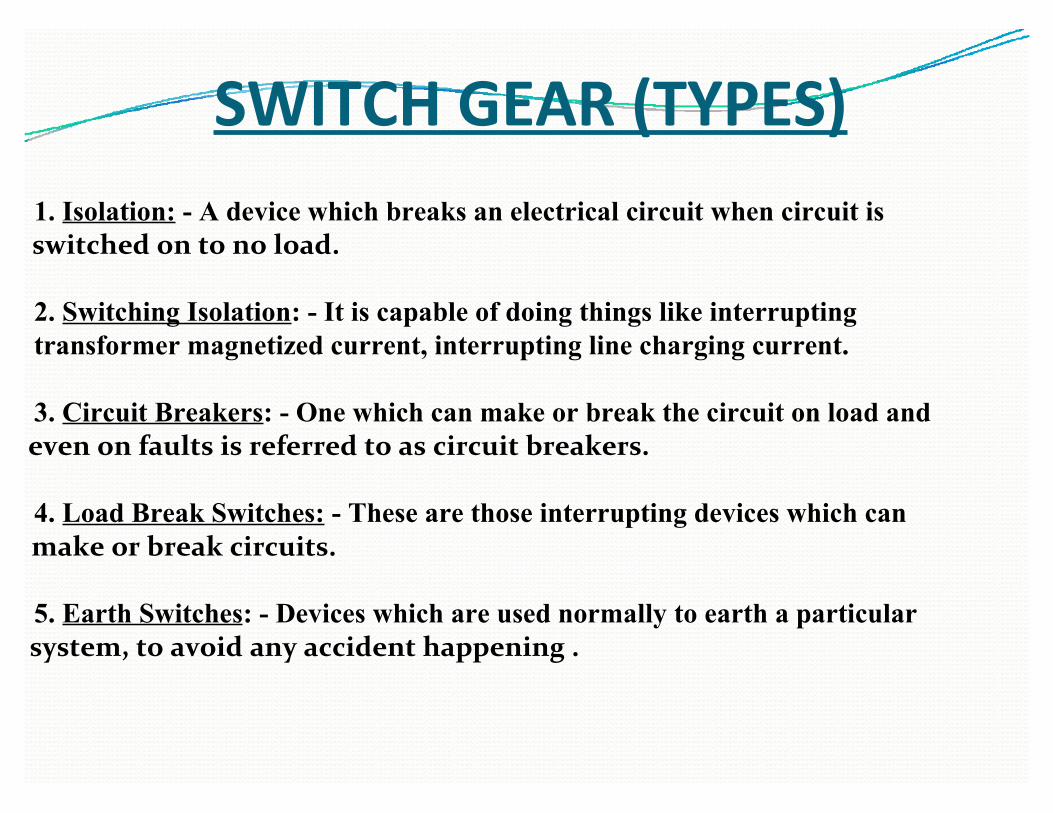
SWITCH GEAR (TYPES)1. Isolation: - A device which breaks an electrical circuit when circuit isswitched on to no load.
2. Switching Isolation: - It is capable of doing things like interruptingtransformer magnetized current, interrupting line charging current.
3. Circuit Breakers: - One which can make or break the circuit on load andeven on faults is referred to as circuit breakers.
4. Load Break Switches: - These are those interrupting devices which canmake or break circuits.
5. Earth Switches: - Devices which are used normally to earth a particularsystem, to avoid any accident happening .
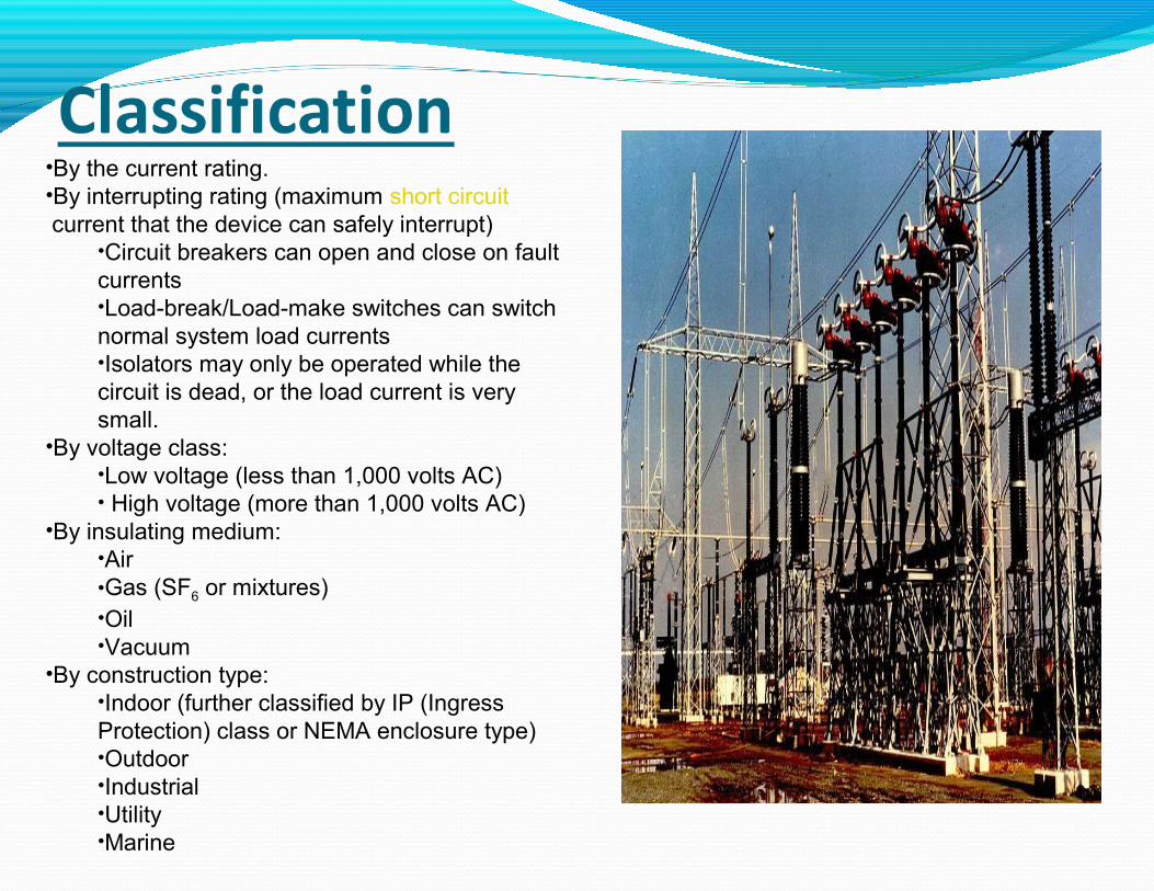
•By the current rating.•By interrupting rating (maximum short circuit current that the device can safely interrupt)
•Circuit breakers can open and close on fault currents•Load-break/Load-make switches can switch normal system load currents•Isolators may only be operated while the circuit is dead, or the load current is very small.
•By voltage class:•Low voltage (less than 1,000 volts AC)• High voltage (more than 1,000 volts AC)
•By insulating medium:•Air•Gas (SF6 or mixtures)•Oil•Vacuum
•By construction type:•Indoor (further classified by IP (Ingress Protection) class or NEMA enclosure type)•Outdoor•Industrial•Utility•Marine
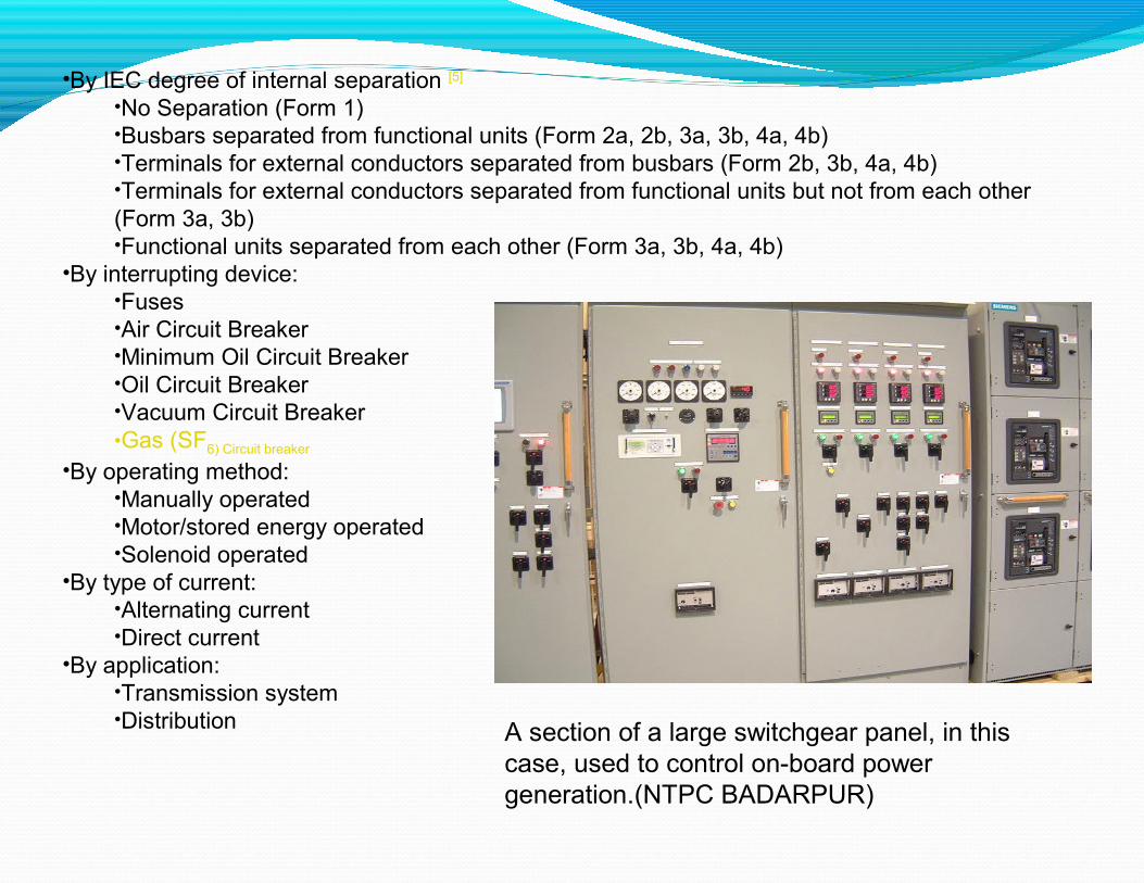
•By IEC degree of internal separation [5]
•No Separation (Form 1)•Busbars separated from functional units (Form 2a, 2b, 3a, 3b, 4a, 4b)•Terminals for external conductors separated from busbars (Form 2b, 3b, 4a, 4b)•Terminals for external conductors separated from functional units but not from each other (Form 3a, 3b)•Functional units separated from each other (Form 3a, 3b, 4a, 4b)
•By interrupting device:•Fuses•Air Circuit Breaker•Minimum Oil Circuit Breaker•Oil Circuit Breaker•Vacuum Circuit Breaker•Gas (SF6) Circuit breaker
•By operating method:•Manually operated•Motor/stored energy operated•Solenoid operated
•By type of current:•Alternating current•Direct current
•By application:•Transmission system•Distribution A section of a large switchgear panel, in this
case, used to control on-board power generation.(NTPC BADARPUR)

SWITCHGEAR(Mf. By Bhel)

Circuit breaker
• circuit breaker (popularly known as CB) is an automatically operated electrical switch designed to protect an electrical circuit from damage caused by overload or short circuit.
• Its basic function is to detect a fault condition and, by interrupting continuity, to immediately discontinue electrical flow.
400 kV SF6 live tank circuit breakers
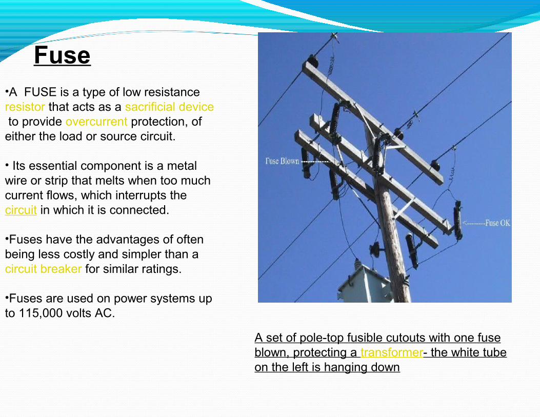
Fuse•A FUSE is a type of low resistance resistor that acts as a sacrificial device to provide overcurrent protection, of either the load or source circuit.
• Its essential component is a metal wire or strip that melts when too much current flows, which interrupts the circuit in which it is connected.
•Fuses have the advantages of often being less costly and simpler than a circuit breaker for similar ratings.
•Fuses are used on power systems up to 115,000 volts AC.
A set of pole-top fusible cutouts with one fuse blown, protecting a transformer- the white tube on the left is hanging down

Contactor
•A contactor is an electrically controlled switch used for switching a power circuit, similar to a relay except with higher current ratings. . Unlike a circuit breaker, a contactor is not intended to interrupt a short circuitcurrent. •Contactors range from those having a breaking current of several amperes to thousands of amperes and 24 V DC to many kilovolts.
•Contactors are used to control electric motors, lighting, heating, capacitor banks, and other electrical loads.
480 VOLT CONTACTOR PANEL.
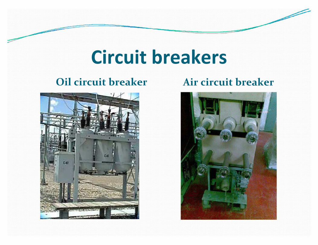
Circuit breakersOil circuit breaker Air circuit breaker

Sf6 Circuit breaker Vaccum circuit breaker

STATOR•The stator winding is made up of insulated copper conductor bars that are distributed around the the inside diameter of the stator core.
•Each slot contains two conductor bars,one on top of the other .
•The stator winding is divided into three phases,which are alwys wye connected.
•The distribution is done to produce 120 degree difference in the voltage peaks from one phase to the other,hence the term “three-phase voltage.

ROTOR•.The rotor winding is installed in the slots machined and is distributed symmetrically around the rotor between the poles.
•. The coils are wound into the winding slots in the forging ,concentrically in corresponding positions on opposite sides of a pole.
•.The series connection essentially creates a single multi-turn overall, that develops the total ampere-turns of the rotor
•Silver bearing copper is used for the winding with mica as the insulation A mechanically strong insulator such as minacity is used for lining the slots.

Power Transformer• Transformer is a device that transfers electrical energy from one circuit to another by magnetic coupling with out requiring relative motion between its parts.
•It usually comprises two or more coupled windings, and inmost cases, a core to concentrate magnetic flux.
•An alternating voltage applied to one winding creates a time-varying magnetic flux in the core, which includes a voltage in the other windings.

•No load voltage (hv) - 229 KV•No load Voltage (lv) -10.5 KV•Line current (hv) - 315.2 A•Line current (lv) - 873.2 A•Temp rise - 45 Celsius•Oil quantity -40180 lit•Weight of oil -34985 Kg•Total weight - 147725 Kg•Core & winding - 84325 Kg•Phase - 3•Frequency - 50 Hz
Rating of transformer (NTPC BADARPUR)

REFERENCES
The following matter has been taken from the following-
y NTPC libraryy Google internet browsery P.S Bhimbra

THANKYOU