finaldraft best practices for installation 170410
TRANSCRIPT

MoCA® TechnologyInstallation Best Practices for a Home Network
MoCA® Technology Installation Best Practices for a Home Network
March2017

Copyright © 2017 Multimedia Over Coax Alliance. All Rights Reserved. MoCA is a trademark or registered trademark of the Multimedia Over Coax Alliance in the United States and other countries.
IMPORTANTNOTICE.THISDOCUMENTANDTHEINFORMATIONCONTAINEDHEREINAREPROVIDED"ASIS"AND“WITH ALL FAULTS”. NEITHER MOCA NOR ANY MEMBER OF MOCA MAKES ANY REPRESENTATIONS ORWARRANTIES OF ANY KINDWHATSOEVERWITH RESPECT TO (A) THIS DOCUMENT, (B) ANY PRODUCT THAT ISDEVELOPEDORMANUFACTURED IN ACCORDANCEWITH THE SPECIFICATIONS IN THIS DOCUMENT OR (C) THEINTEROPERABILITYOFANYSUCHPRODUCTWITHANYOTHERPRODUCT. MOCAANDMOCAMEMBERSDISCLAIMALL IMPLIEDWARRANTIES, INCLUDINGWITHOUTLIMITATIONTHEIMPLIEDWARRANTIESOFMERCHANTABILITY,FITNESS FOR A PARTICULAR PURPOSE, ACCURACY, NON-INFRINGEMENT AND TITLE. NEITHERMOCA NOR ANYMEMBEROFMOCAMAKESANYREPRESENTATIONSORWARRANTIESTHATTHECONTENTSOFTHEDOCUMENTARE COMPLETE, ACCURATE OR SUITABLE FOR ANY PURPOSE OR THAT ANY PRODUCT OR OTHERIMPLEMENTATIONOFSUCHCONTENTSWILLNOTINFRINGEANYPATENTS,COPYRIGHTSOROTHERRIGHTS. INNOEVENTWILLMOCAORANYMOCAMEMBERBELIABLEFORANYLOSSES,INVESTMENTSMADE,LIABILITIES,LOSSOF PROFITS, LOSS OF BUSINESS, LOSS OF USE OF DATA, INTERRUPTION OF BUSINESS, OR FOR ANY DIRECT,INDIRECT, SPECIAL OR EXEMPLARY, INCIDENTIAL, PUNITIVE OR CONSEQUENTIAL DAMAGES OF ANY KIND, INCONTRACT, TORT, NEGLIGENCE OR OTHER LEGAL THEORY, INCLUDINGWITHOUT LIMITATION IN CONNECTIONWITH THE USE OF THIS DOCUMENT, THE INFORMATION CONTAINED HEREIN OR ANY PRODUCT ORIMPLEMENTATION,EVEN IFADVISEDOFTHEPOSSIBILITY THEREOF. USEOFTHISDOCUMENT ISATYOURSOLERISK. FROMTIMETOTIMEMOCAMAY ISSUE IMPROVEMENTS,ENHANCEMENTSANDOTHERCHANGESTOTHESPECIFICATIONDESCRIBEDINTHISDOCUMENT.
TableofContents1 Introduction..........................................................................................................................................4
1.1 Overview........................................................................................................................................51.2 MoCAtechnology,areview...........................................................................................................51.3 MoCAVersionsandProfiles...........................................................................................................51.4 TermsandDefinitions....................................................................................................................7
2 KeyMoCAParameters..........................................................................................................................92.1 Frequency......................................................................................................................................9
2.1.1 FrequencyBands....................................................................................................................92.1.2 MoCAChannels......................................................................................................................9
2.2 PHYRate.......................................................................................................................................102.3 Power...........................................................................................................................................11
2.3.1 TransmitPower....................................................................................................................112.3.2 ReceivePower......................................................................................................................11
2.4 PhysicalMedium&Devices..........................................................................................................122.4.1 Coax.....................................................................................................................................122.4.2 F-Connectors.......................................................................................................................132.4.3 Splitters................................................................................................................................132.4.4 DirectionalCoupler..............................................................................................................142.4.5 POEFilter.............................................................................................................................142.4.6 Amplifiers.............................................................................................................................15
3 InstallationPractice.............................................................................................................................153.1 InstallationSummary...................................................................................................................15
3.1.1 LocationandWiring.............................................................................................................163.1.2 POEFilterInstallation...........................................................................................................173.1.3 MoCANodeInstallationandVerification.............................................................................17
3.2 CoaxCableSelection....................................................................................................................173.3 FrequencySelection.....................................................................................................................183.4 POEFilterSelection......................................................................................................................183.5 SplitterSelection..........................................................................................................................183.6 MoCACompatibleAmplifiers.......................................................................................................183.7 CornerCases................................................................................................................................18
3.7.1 LongCableRun.....................................................................................................................183.7.2 MultipleMoCANetworks.....................................................................................................19
4 Troubleshooting..................................................................................................................................215 Appendix.............................................................................................................................................23
5.1 Power–dBmtodBmVConversion..............................................................................................23

ListofFiguresFigure1ExampleMoCAConnection...................................................................................................................5Figure2MoCATechnologyComparison..............................................................................................................6Figure3MoCA4-NodePHYRateExample........................................................................................................10Figure4Exampleof1:2and1:4Splitters..........................................................................................................13Figure5UnityGainAmplifier(UGA)..................................................................................................................15Figure6ExampleofHomeRunWiring..............................................................................................................16Figure7ExampleofAddinga2ndDevice.........................................................................................................16Figure8TypicalPOEFilterInstallation..............................................................................................................17Figure9LongCableRunwithoutSTBs.............................................................................................................19Figure10LongCableRunwithSTB...................................................................................................................19Figure11ManyNodes.......................................................................................................................................20Figure12ManyNodeswithoutSTBs.................................................................................................................21
ListofTablesTable1SummaryofMoCAVersions...................................................................................................................6Table2MoCAFrequencyBands..........................................................................................................................9Table3BandDChannelFrequencyAssignment.................................................................................................9Table4BandEChannelFrequencyAssignment................................................................................................10Table5BandFChannelFrequencyAssignment................................................................................................10Table6ExpectedMaximumPHYRates.............................................................................................................11Table7SummaryofMoCATransmitPower......................................................................................................11Table8MinimumRecievePower......................................................................................................................12Table9TypicalCoaxCableAttenuationat1GHzper100ft.............................................................................13Table10TypicalSplitterAttenuation................................................................................................................14
1 Introduction
1.1 OverviewThis document describes the best practices for installation of a Home Network using MoCA®technology.TheintendedaudienceishomenetworkingandserviceproviderinstallersaswellasanyonedevelopingmethodsandproceduresforinstallationofMoCAtechnology.Thefollowing isasummaryofMoCAtechnologyusedfor installation.PleaserefertotheMoCAspecificationsformoredetailaboutdesign,implementation,testing,andcertification.MoCA® technology is the fastest andmost reliable in-homebackbone forWi-Fi® andhasbeenadopted by cable, telco/IPTV and satellite operators worldwide. MoCA 2.0 offers actualthroughputs (MAC rate) up to 1 Gbps and MoCA 2.5 is capable of up to 2.5 Gbps actualthroughput.MoCA2.1andMoCA2.5alsooffer anadditional setofnetworkmanagementandsecurityfeatures.TheAlliancehasrecentlyenteredintothebroadbandaccessmarkettargetingMDUswithMoCAAccess™.ItisbasedonMoCA2.0/2.5andusestheexistingcoaxialcabling.TheAlliancehas225certifiedproductsand45membersworldwide.
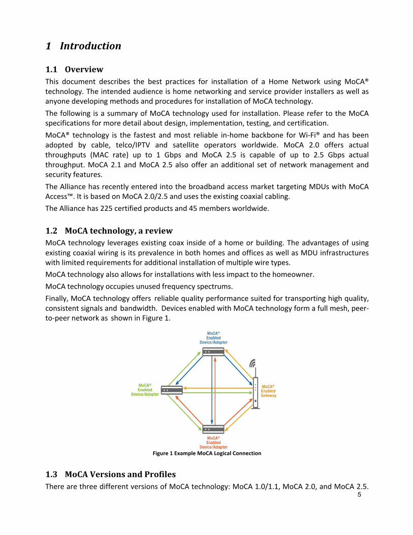
1.2 MoCAtechnology,areviewMoCAtechnology leveragesexistingcoax insideofahomeorbuilding.TheadvantagesofusingexistingcoaxialwiringisitsprevalenceinbothhomesandofficesaswellasMDUinfrastructureswithlimitedrequirementsforadditionalinstallationofmultiplewiretypes.MoCAtechnologyalsoallowsforinstallationswithlessimpacttothehomeowner.MoCAtechnologyoccupiesunusedfrequencyspectrums.Finally,MoCAtechnologyoffers reliablequalityperformancesuitedfortransportinghighquality,consistentsignalsand bandwidth. DevicesenabledwithMoCAtechnologyformafullmesh,peer-to-peernetworkas showninFigure1.
Figure1ExampleMoCALogicalConnection
1.3 MoCAVersionsandProfilesTherearethreedifferentversionsofMoCAtechnology:MoCA1.0/1.1,MoCA2.0,andMoCA2.5.
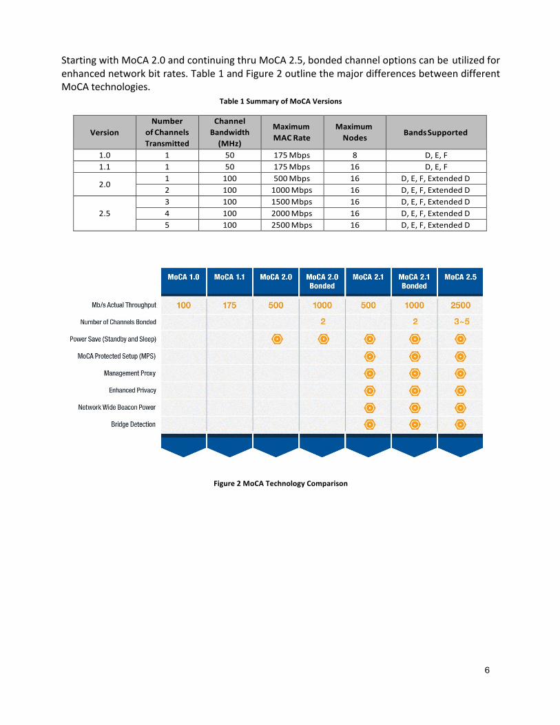
StartingwithMoCA2.0andcontinuingthruMoCA2.5,bondedchanneloptionscanbeutilizedforenhancednetworkbitrates.Table1andFigure2outlinethemajordifferencesbetweendifferentMoCAtechnologies.
Table1SummaryofMoCAVersions
VersionNumber
ofChannelsTransmitted
ChannelBandwidth(MHz)
MaximumMACRate
MaximumNodes BandsSupported
1.0 1 50 175Mbps 8 D,E,F1.1 1 50 175Mbps 16 D,E,F
2.01 100 500Mbps 16 D,E,F,ExtendedD2 100 1000Mbps 16 D,E,F,ExtendedD
2.53 100 1500Mbps 16 D,E,F,ExtendedD4 100 2000Mbps 16 D,E,F,ExtendedD5 100 2500Mbps 16 D,E,F,ExtendedD
Figure2MoCATechnologyComparison
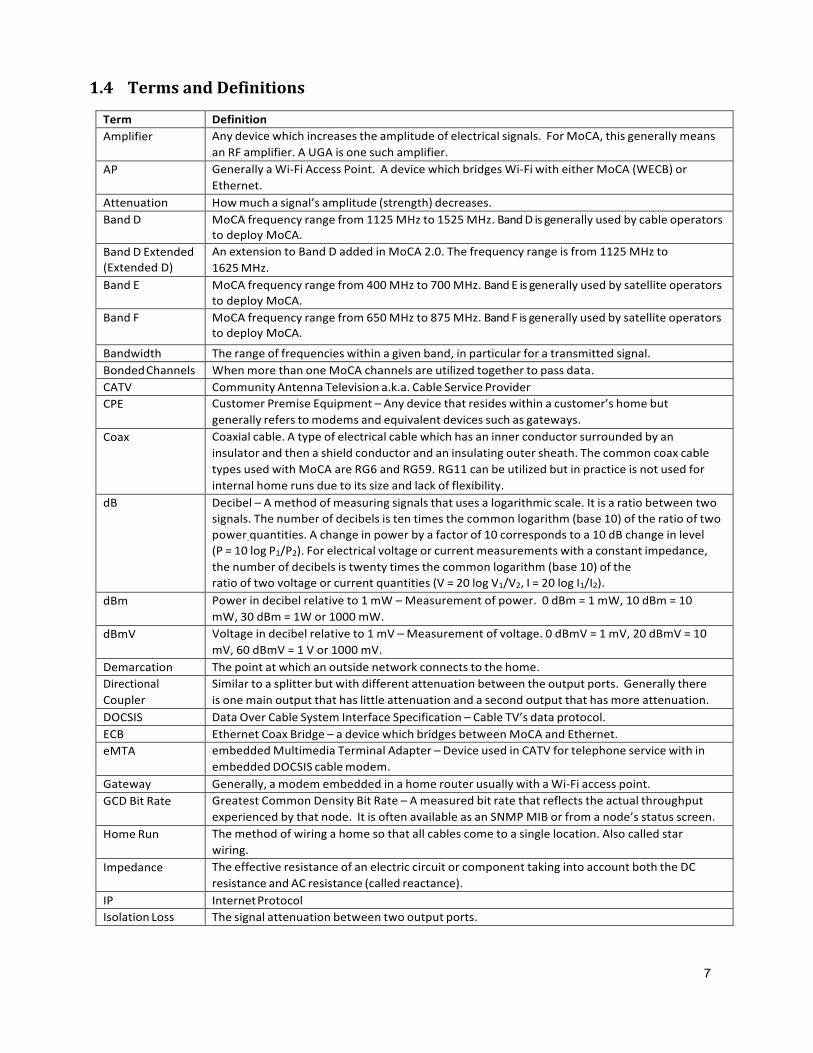
1.4 TermsandDefinitionsTerm DefinitionAmplifier Anydevicewhichincreasestheamplitudeofelectricalsignals. ForMoCA,thisgenerallymeans
anRFamplifier.AUGAisonesuchamplifier.AP GenerallyaWi-FiAccessPoint. AdevicewhichbridgesWi-FiwitheitherMoCA(WECB)or
Ethernet.Attenuation Howmuchasignal’samplitude(strength)decreases.BandD MoCAfrequencyrangefrom1125MHzto1525MHz.BandDisgenerallyusedbycableoperators
todeployMoCA.BandDExtended(ExtendedD)
AnextensiontoBandDaddedinMoCA2.0.Thefrequencyrangeisfrom1125MHzto1625MHz.
BandE MoCAfrequencyrangefrom400MHzto700MHz.BandEisgenerallyusedbysatelliteoperatorstodeployMoCA.
BandF MoCAfrequencyrangefrom650MHzto875MHz.BandFisgenerallyusedbysatelliteoperatorstodeployMoCA.
Bandwidth Therangeoffrequencieswithinagivenband,inparticularforatransmittedsignal.BondedChannels WhenmorethanoneMoCAchannelsareutilizedtogethertopassdata.CATV CommunityAntennaTelevisiona.k.a.CableServiceProviderCPE CustomerPremiseEquipment–Anydevicethatresideswithinacustomer’shomebut
generallyreferstomodemsandequivalentdevicessuchasgateways.Coax Coaxialcable.Atypeofelectricalcablewhichhasaninnerconductorsurroundedbyan
insulatorandthenashieldconductorandaninsulatingoutersheath.ThecommoncoaxcabletypesusedwithMoCAareRG6andRG59.RG11canbeutilizedbutinpracticeisnotusedforinternalhomerunsduetoitssizeandlackofflexibility.
dB Decibel–Amethodofmeasuringsignalsthatusesalogarithmicscale.Itisaratiobetweentwosignals.Thenumberofdecibelsistentimesthecommonlogarithm(base10)oftheratiooftwopowerquantities.Achangeinpowerbyafactorof10correspondstoa10dBchangeinlevel (P=10logP1/P2).Forelectricalvoltageorcurrentmeasurementswithaconstantimpedance,thenumberofdecibelsistwentytimesthecommonlogarithm(base10)oftheratiooftwovoltageorcurrentquantities(V=20logV1/V2,I=20logI1/I2).
dBm Powerindecibelrelativeto1mW–Measurementofpower. 0dBm=1mW,10dBm=10mW,30dBm=1Wor1000mW.
dBmV Voltageindecibelrelativeto1mV–Measurementofvoltage.0dBmV=1mV,20dBmV=10mV,60dBmV=1Vor1000mV.
Demarcation Thepointatwhichanoutsidenetworkconnectstothehome.DirectionalCoupler
Similartoasplitterbutwithdifferentattenuationbetweentheoutputports. Generallythereisonemainoutputthathaslittleattenuationandasecondoutputthathasmoreattenuation.
DOCSIS DataOverCableSystemInterfaceSpecification–CableTV’sdataprotocol.ECB EthernetCoaxBridge–adevicewhichbridgesbetweenMoCAandEthernet.eMTA embeddedMultimediaTerminalAdapter–DeviceusedinCATVfortelephoneservicewithin
embeddedDOCSIScablemodem.Gateway Generally,amodemembeddedinahomerouterusuallywithaWi-Fiaccesspoint.GCDBitRate GreatestCommonDensityBitRate–Ameasuredbitratethatreflectstheactualthroughput
experiencedbythatnode. ItisoftenavailableasanSNMPMIBorfromanode’sstatusscreen.HomeRun Themethodofwiringahomesothatallcablescometoasinglelocation.Alsocalledstar
wiring.Impedance TheeffectiveresistanceofanelectriccircuitorcomponenttakingintoaccountboththeDC
resistanceandACresistance(calledreactance).IP InternetProtocolIsolationLoss Thesignalattenuationbetweentwooutputports.
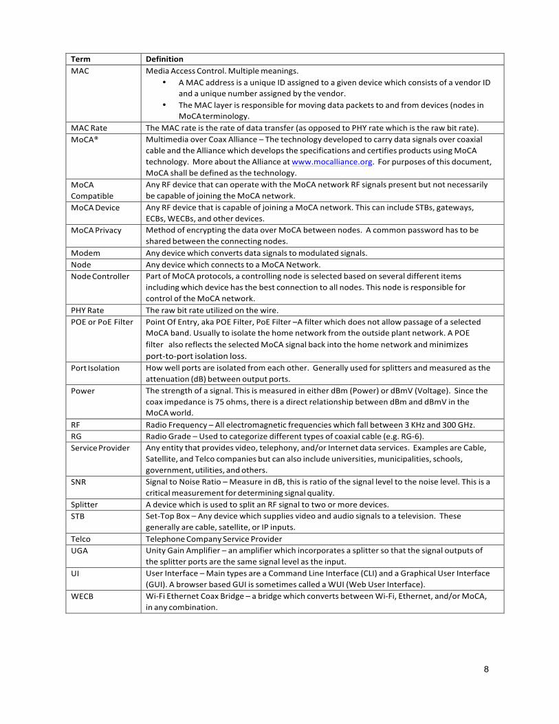
Term DefinitionMAC MediaAccessControl.Multiplemeanings.
• AMACaddressisauniqueIDassignedtoagivendevicewhichconsistsofavendorIDandauniquenumberassignedbythevendor.
• TheMAClayerisresponsibleformovingdatapacketstoandfromdevices(nodesinMoCAterminology.
MACRate TheMACrateistherateofdatatransfer(asopposedtoPHYratewhichistherawbitrate).MoCA® MultimediaoverCoaxAlliance–Thetechnologydevelopedtocarrydatasignalsovercoaxial
cableandtheAlliancewhichdevelopsthespecificationsandcertifiesproductsusingMoCAtechnology.MoreabouttheAllianceatwww.mocalliance.org. Forpurposesofthisdocument,MoCAshallbedefinedasthetechnology.
MoCACompatible
AnyRFdevicethatcanoperatewiththeMoCAnetworkRFsignalspresentbutnotnecessarilybecapableofjoiningtheMoCAnetwork.
MoCADevice AnyRFdevicethatiscapableofjoiningaMoCAnetwork.ThiscanincludeSTBs,gateways,ECBs,WECBs,andotherdevices.
MoCAPrivacy MethodofencryptingthedataoverMoCAbetweennodes. Acommonpasswordhastobesharedbetweentheconnectingnodes.
Modem Anydevicewhichconvertsdatasignalstomodulatedsignals.Node AnydevicewhichconnectstoaMoCANetwork.NodeController PartofMoCAprotocols,acontrollingnodeisselectedbasedonseveraldifferentitems
includingwhichdevicehasthebestconnectiontoallnodes.ThisnodeisresponsibleforcontroloftheMoCAnetwork.
PHYRate Therawbitrateutilizedonthewire.POEorPoEFilter PointOfEntry,akaPOEFilter,PoEFilter–Afilterwhichdoesnotallowpassageofaselected
MoCAband.Usuallytoisolatethehomenetworkfromtheoutsideplantnetwork.APOEfilter alsoreflectstheselectedMoCAsignalbackintothehomenetworkandminimizesport-to-portisolationloss.
PortIsolation Howwellportsareisolatedfromeachother. Generallyusedforsplittersandmeasuredastheattenuation(dB)betweenoutputports.
Power Thestrengthofasignal.ThisismeasuredineitherdBm(Power)ordBmV(Voltage). Sincethecoaximpedanceis75ohms,thereisadirectrelationshipbetweendBmanddBmVintheMoCAworld.
RF RadioFrequency–Allelectromagneticfrequencieswhichfallbetween3KHzand300GHz.RG RadioGrade–Usedtocategorizedifferenttypesofcoaxialcable(e.g.RG-6).ServiceProvider Anyentitythatprovidesvideo,telephony,and/orInternetdataservices. ExamplesareCable,
Satellite,andTelcocompaniesbutcanalsoincludeuniversities,municipalities,schools,government,utilities,andothers.
SNR SignaltoNoiseRatio–MeasureindB,thisisratioofthesignalleveltothenoiselevel.Thisisacriticalmeasurementfordeterminingsignalquality.
Splitter AdevicewhichisusedtosplitanRFsignaltotwoormoredevices.STB Set-TopBox–Anydevicewhichsuppliesvideoandaudiosignalstoatelevision. These
generallyarecable,satellite,orIPinputs.Telco TelephoneCompanyServiceProviderUGA UnityGainAmplifier–anamplifierwhichincorporatesasplittersothatthesignaloutputsof
thesplitterportsarethesamesignallevelastheinput.UI UserInterface–MaintypesareaCommandLineInterface(CLI)andaGraphicalUserInterface
(GUI).AbrowserbasedGUIissometimescalledaWUI(WebUserInterface).WECB Wi-FiEthernetCoaxBridge–abridgewhichconvertsbetweenWi-Fi,Ethernet,and/orMoCA,
inanycombination.
2 KeyMoCAParametersThefollowingisadescriptionofthekeyMoCAparameterswithrespecttoinstallation.
2.1 Frequency
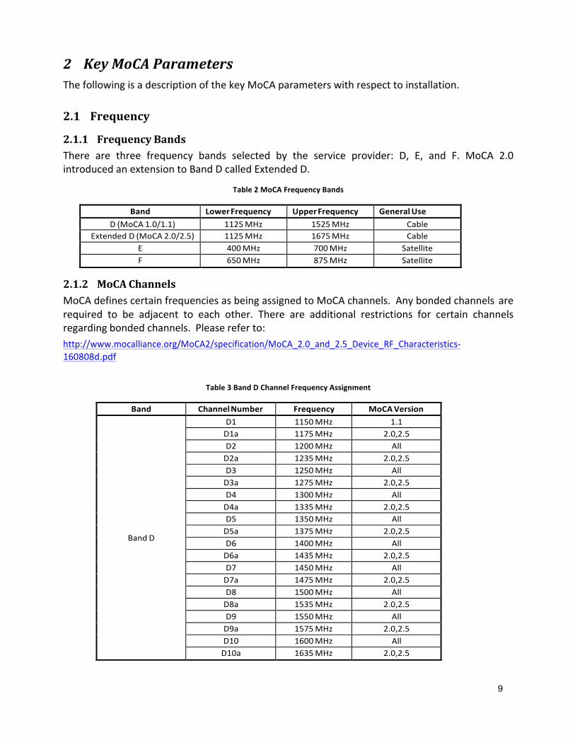
2.1.1 FrequencyBandsThere are three frequency bands selected by the service provider: D, E, and F. MoCA 2.0introducedanextensiontoBandDcalledExtendedD.
Table2MoCAFrequencyBands
Band LowerFrequency UpperFrequency GeneralUseD(MoCA1.0/1.1) 1125MHz 1525MHz Cable
ExtendedD(MoCA2.0/2.5) 1125MHz 1675MHz CableE 400MHz 700MHz SatelliteF 650MHz 875MHz Satellite
2.1.2 MoCAChannelsMoCAdefinescertainfrequenciesasbeingassignedtoMoCAchannels. Anybondedchannels arerequired to be adjacent to each other. There are additional restrictions for certain channelsregardingbondedchannels. Pleasereferto:http://www.mocalliance.org/MoCA2/specification/MoCA_2.0_and_2.5_Device_RF_Characteristics-160808d.pdf
Table3BandDChannelFrequencyAssignment
Band ChannelNumber Frequency MoCAVersion
BandD
D1 1150MHz 1.1D1a 1175MHz 2.0,2.5D2 1200MHz AllD2a 1235MHz 2.0,2.5D3 1250MHz AllD3a 1275MHz 2.0,2.5D4 1300MHz AllD4a 1335MHz 2.0,2.5D5 1350MHz AllD5a 1375MHz 2.0,2.5D6 1400MHz AllD6a 1435MHz 2.0,2.5D7 1450MHz AllD7a 1475MHz 2.0,2.5D8 1500MHz AllD8a 1535MHz 2.0,2.5D9 1550MHz AllD9a 1575MHz 2.0,2.5D10 1600MHz AllD10a 1635MHz 2.0,2.5
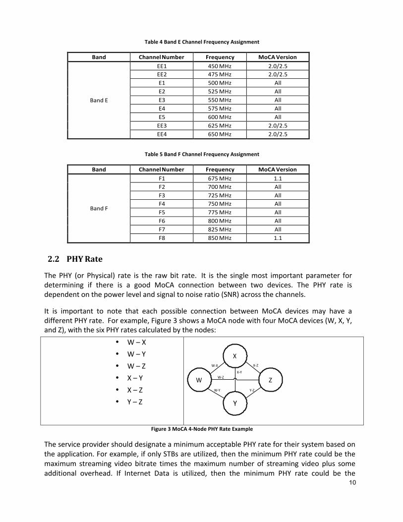
Table4BandEChannelFrequencyAssignment
Band ChannelNumber Frequency MoCAVersion
BandE
EE1 450MHz 2.0/2.5EE2 475MHz 2.0/2.5E1 500MHz AllE2 525MHz AllE3 550MHz AllE4 575MHz AllE5 600MHz AllEE3 625MHz 2.0/2.5EE4 650MHz 2.0/2.5
Table5BandFChannelFrequencyAssignment
Band ChannelNumber Frequency MoCAVersion
BandF
F1 675MHz 1.1F2 700MHz AllF3 725MHz AllF4 750MHz AllF5 775MHz AllF6 800MHz AllF7 825MHz AllF8 850MHz 1.1
2.2 PHYRate
ThePHY (or Physical) rate is the rawbit rate. It is the singlemost important parameter fordetermining if there is a good MoCA connection between two devices. The PHY rate isdependentonthepowerlevelandsignaltonoiseratio(SNR)acrossthechannels.
It is important to note that each possible connection between MoCA devices may have adifferentPHYrate. Forexample,Figure3showsaMoCAnodewithfourMoCAdevices(W,X,Y,andZ),withthesixPHYratescalculatedbythenodes:
• W–X• W–Y• W–Z• X–Y• X–Z• Y–Z
Figure3MoCA4-NodePHYRateExample
TheserviceprovidershoulddesignateaminimumacceptablePHYratefortheirsystembasedontheapplication.Forexample,ifonlySTBsareutilized,thentheminimumPHYratecouldbethemaximum streaming video bitrate times themaximumnumber of streaming video plus someadditional overhead. If Internet Data is utilized, then the minimum PHY rate could be the
X-Z
X-Y
Z
Y

expectedmaximumPHYrate.PleasecheckwithyourserviceproviderforthelowestacceptablePHYrate.Table6showsthemaximumPHYratesforthedifferentMoCAversionsandprofiles.
Table6ExpectedMaximumPHYRates
Version BandChannels ExpectedMaximum
PHYRate11(Mesh)
1.0/1.1D 1 225MbpsE,F 1 240Mbps
2.0 D,ExtD,E,F1 600Mbps2 1200Mbps
2.5
D,ExtD,E,F 1 600MbpsD,ExtD,E,F 2 1200MbpsD,ExtD 3 1800MbpsD,ExtD 4 2400MbpsD,ExtD 5 3000Mbps
NOTE:There is amode inMoCA2.0 calledTurbomode,whichexistswhen thereareonly twoMoCAdevicespresent.Whenthisisrecognized,someoftheoverheadtransactionsareremovedtherebygivinga12%increaseinPHYrate.
2.3 PowerThis is the strength of theMoCA signal, both transmitted and received. The received power isdependentontheattenuationbetweenthetransmitdeviceandthereceivedevice.The power values give a good indication of the quality of the signal between differentMoCAdeviceswhichrelatesdirectlytothePHYrate.
2.3.1 TransmitPowerMoCA performs a ranging function such that the power level transmitted from one node toanothernode isdependentontheattenuation.Thehighest level is theMaximumOutputvaluewhichhasawiderangeduetomanufacturingissues.Table7outlinesthedifferentpowerlevelsforthedifferentversionsandprofilesofMoCA.
Table7SummaryofMoCATransmitPower
Version
NumberofChannelsTransmitted
ChannelBandwidth(MHz)
MaximumOutputPowerperChannel
MaximumOutputPowerTotal forall
TransmittedChannels1.0/1.1 1 50 -1dBmto+7dBm -1dBmto+7dBm
2.01 100 -3dBmto+5dBm 0dBmto+8dBm2 100 -4.5dBmto+3.5dBm +0.3dBmto+8.3dBm
2.5
3 100 -5.3dBmto+2.7dBm +0.7dBmto+8.7dBm4 100 -6dBmto+2dBm +1dBmto+9dBm5 100 -1dBmto+7dBm -1dBmto+7dBm
2.3.2 ReceivePower1 Actual value may be higher depending on vendor implementation. These values are theminimumsrequiredbytheMoCAspecifications.

TheminimumPHYrateforaMoCAdeviceisdependentonaminimumsignallevelatthechannelfrequencyaswellastheSNR.Signal levelsbelowthisratewillstillcommunicatebutata lowerPHYrate.ForanexplanationofdBmVanddBm,pleaserefertosection5.1TheminimumsignalleveltomeettheminimumPHYrateisdependentonthefrequencybandasshowninTable8.
Table8MinimumRecievePower
Version BandMinimumReceive
PowerPHYRate
1.0/1.1D -51dBm(-2.25dBmV) 225MbpsE,F -49dBm(-0.25dBmV) 240Mbps
2.0 D -44dBm 600Mbps/ChannelE,F -43dBm 600Mbps/Channel
2.5 D,E,F -42dBm 650Mbps/Channel
2.4 PhysicalMedium&Devices
2.4.1 CoaxCoaxial cable, also called coax, is any cable that consists of an inner conductor surrounded byinsulation,ashieldconductor,andaninsulatingjacket.
Each typeof coax cable isdesigned toprovidea characteristic impedance. For thepurposesofMoCAdiscussion,only75ohmcableisutilized.Therearethreemaintypesof75ohmcoaxtypicallyutilizedinMoCAdeployments:
• RG-6 –Most common used today for in-homewiring, very flexiblewith relatively lowattenuation.
• RG-11 – Larger and less flexible than RG-6, primarily used for outside wiring, lowestattenuation.
• RG-59–Smallestofthecommon75-ohmcoaxcables,rarelyusedfornewinstallations,highestattenuation.
Themost importantconsiderationforagoodMoCAconnection isattenuation,especially inthecoaxcable.Theattenuationisdependentonthetypeofcable,theMoCAchannelfrequency,andthelengthofcable.Table9canbeusedtocalculatetheattenuation.
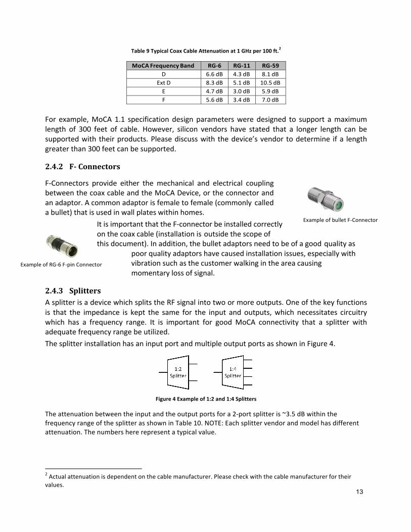
Table9TypicalCoaxCableAttenuationat1GHzper100ft.2
MoCAFrequencyBand RG-6 RG-11 RG-59D 6.6dB 4.3dB 8.1dB
ExtD 8.3dB 5.1dB 10.5dBE 4.7dB 3.0dB 5.9dBF 5.6dB 3.4dB 7.0dB
For example,MoCA1.1 specification design parameterswere designed to support amaximumlength of 300 feet of cable. However, silicon vendors have stated that a longer length can besupportedwith theirproducts.Pleasediscusswith thedevice’svendor todetermine ifa lengthgreaterthan300feetcanbesupported.
2.4.2 F-Connectors
F-Connectors provide either the mechanical and electrical couplingbetweenthecoaxcableandtheMoCADevice,ortheconnectorandanadaptor.Acommonadaptorisfemaletofemale(commonly calledabullet)thatisusedinwallplateswithinhomes.
ItisimportantthattheF-connectorbeinstalledcorrectlyonthecoaxcable(installationisoutsidethescopeofthisdocument).Inaddition,thebulletadaptorsneedtobeofagoodqualityas
poorqualityadaptorshavecausedinstallationissues,especiallywithvibrationsuchasthecustomerwalkingintheareacausingmomentarylossofsignal.
2.4.3 SplittersAsplitterisadevicewhichsplitstheRFsignalintotwoormoreoutputs.Oneofthekeyfunctionsis that the impedance is kept the same for the input and outputs,which necessitates circuitrywhich has a frequency range. It is important for goodMoCA connectivity that a splitter withadequatefrequencyrangebeutilized.ThesplitterinstallationhasaninputportandmultipleoutputportsasshowninFigure4.
Figure4Exampleof1:2and1:4Splitters
Theattenuationbetweentheinputandtheoutputportsfora2-portsplitteris~3.5dBwithinthefrequencyrangeofthesplitterasshowninTable10.NOTE:Eachsplittervendorandmodelhasdifferentattenuation.Thenumbershererepresentatypicalvalue.
2Actualattenuationisdependentonthecablemanufacturer.Pleasecheckwiththecablemanufacturerfortheirvalues.
ExampleofbulletF-Connector
ExampleofRG-6F-pinConnector
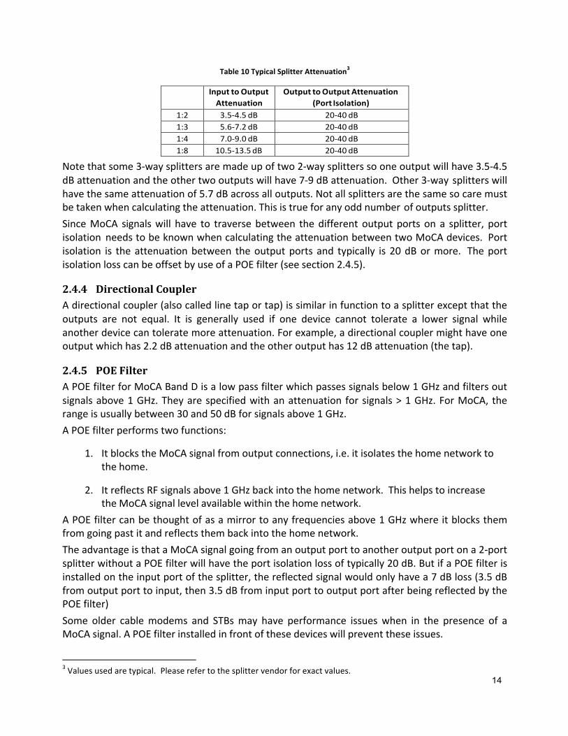
Table10TypicalSplitterAttenuation3
InputtoOutputAttenuation
OutputtoOutputAttenuation(PortIsolation)
1:2 3.5-4.5dB 20-40dB1:3 5.6-7.2dB 20-40dB1:4 7.0-9.0dB 20-40dB1:8 10.5-13.5dB 20-40dB
Notethatsome3-waysplittersaremadeupoftwo2-waysplitterssooneoutputwillhave3.5-4.5dBattenuationandtheothertwooutputswillhave7-9dBattenuation. Other3-way splitterswillhavethesameattenuationof5.7dBacrossalloutputs.Notallsplittersarethesamesocaremustbetakenwhencalculatingtheattenuation.Thisistrueforanyoddnumberofoutputssplitter.SinceMoCA signalswill have to traversebetween thedifferentoutputportson a splitter, portisolation needstobeknownwhencalculatingtheattenuationbetweentwoMoCAdevices. Portisolation is theattenuationbetween theoutputports and typically is 20dBormore. TheportisolationlosscanbeoffsetbyuseofaPOEfilter(seesection2.4.5).
2.4.4 DirectionalCouplerAdirectionalcoupler(alsocalledlinetaportap)issimilarinfunctiontoasplitterexceptthattheoutputs are not equal. It is generally used if one device cannot tolerate a lower signal whileanotherdevicecantoleratemoreattenuation.Forexample,adirectionalcouplermighthaveoneoutputwhichhas2.2dBattenuationandtheotheroutputhas12dBattenuation(thetap).
2.4.5 POEFilterAPOEfilterforMoCABandDisalowpassfilterwhichpassessignalsbelow1GHzandfiltersoutsignalsabove1GHz.Theyarespecifiedwithanattenuation forsignals>1GHz.ForMoCA, therangeisusuallybetween30and50dBforsignalsabove1GHz.APOEfilterperformstwofunctions:
1. ItblockstheMoCAsignalfromoutputconnections,i.e.itisolatesthehomenetworktothehome.
2. ItreflectsRFsignalsabove1GHzbackintothehomenetwork. ThishelpstoincreasetheMoCAsignallevelavailablewithinthehomenetwork.
APOEfiltercanbethoughtofasamirrortoanyfrequenciesabove1GHzwhereitblocksthemfromgoingpastitandreflectsthembackintothehomenetwork.TheadvantageisthataMoCAsignalgoingfromanoutputporttoanotheroutputportona2-portsplitterwithoutaPOEfilterwillhavetheportisolationlossoftypically20dB.ButifaPOEfilterisinstalledontheinputportofthesplitter,thereflectedsignalwouldonlyhavea7dBloss(3.5dBfromoutputporttoinput,then3.5dBfrominputporttooutputportafterbeingreflectedbythePOEfilter)Some older cablemodems and STBsmay have performance issueswhen in the presence of aMoCAsignal.APOEfilterinstalledinfrontofthesedeviceswillpreventtheseissues.
3Valuesusedaretypical. Pleaserefertothesplittervendorforexactvalues.
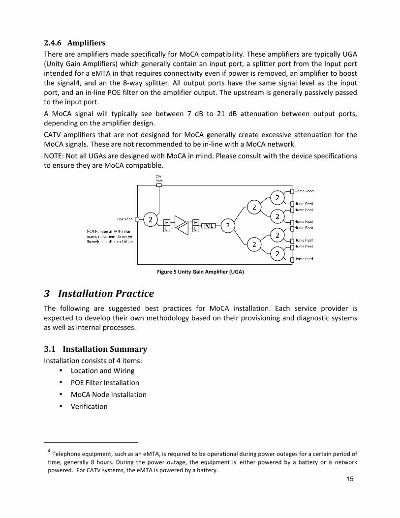
2.4.6 AmplifiersThereareamplifiersmadespecificallyforMoCAcompatibility.TheseamplifiersaretypicallyUGA(UnityGainAmplifiers)whichgenerallycontainaninputport,asplitterportfromtheinputportintendedforaeMTAinthatrequiresconnectivityevenifpowerisremoved,anamplifiertoboostthe signal4, andan the8-way splitter.All outputportshave the same signal level as the inputport,andanin-linePOEfilterontheamplifieroutput.Theupstreamisgenerallypassivelypassedtotheinputport.A MoCA signal will typically see between 7 dB to 21 dB attenuation between output ports,dependingontheamplifierdesign.CATVamplifiers that arenotdesigned forMoCAgenerally createexcessiveattenuation for theMoCAsignals.Thesearenotrecommendedtobein-linewithaMoCAnetwork.NOTE:NotallUGAsaredesignedwithMoCAinmind.PleaseconsultwiththedevicespecificationstoensuretheyareMoCAcompatible.
Figure5UnityGainAmplifier(UGA)
3 InstallationPracticeThe following are suggested best practices for MoCA installation. Each service provider isexpectedtodeveloptheirownmethodologybasedontheirprovisioninganddiagnosticsystemsaswellasinternalprocesses.
3.1 InstallationSummaryInstallationconsistsof4items:
• LocationandWiring• POEFilterInstallation• MoCANodeInstallation• Verification
4Telephoneequipment,suchasaneMTA,isrequiredtobeoperationalduringpoweroutagesforacertainperiodoftime, generally 8 hours. During the power outage, the equipment is either powered by a battery or is networkpowered. ForCATVsystems,theeMTAispoweredbyabattery.
3.1.1 LocationandWiring
3.1.1.1 LocationAnalysisMake a determination onwhere theMoCA devices need to reside. For example, if theMoCAdevice isaSTB, then itwillbe locatedby the television. If it isaWi-Fiaccesspoint (AP),and ifwiringalreadyexistsinthegeneralareaofthedesiredlocationoftheAP,itissuggestedthatitbeplacedthere.
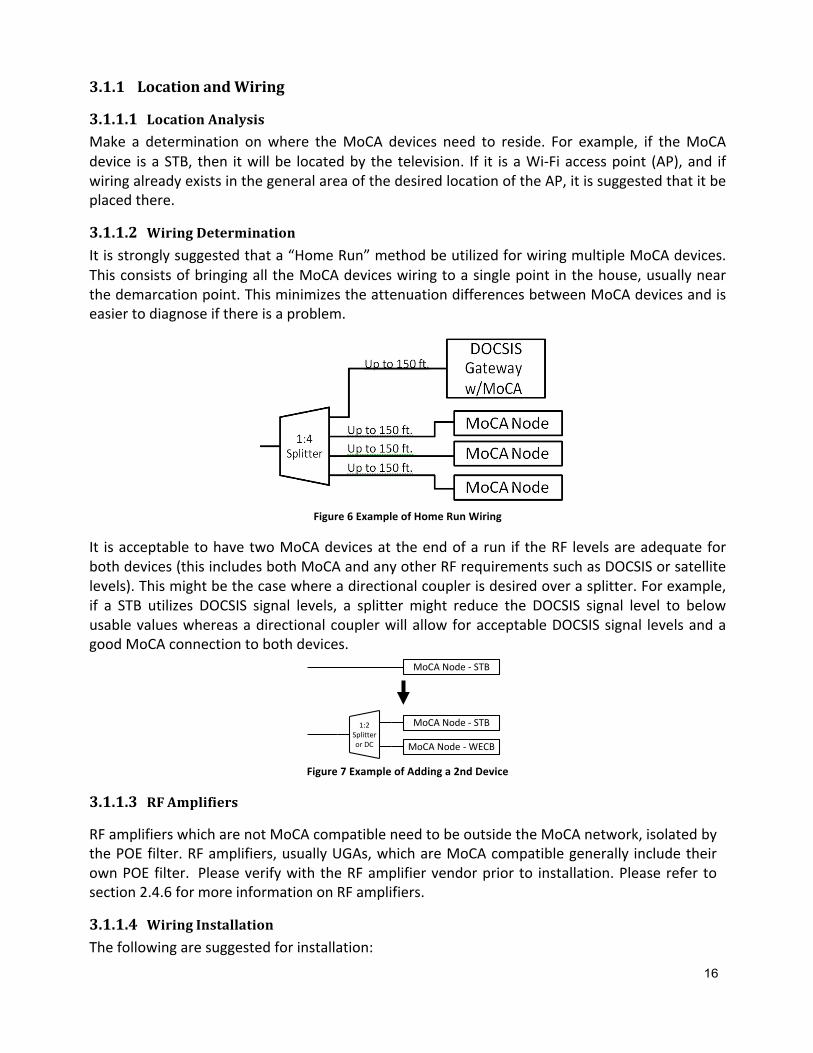
3.1.1.2 WiringDeterminationItisstronglysuggestedthata“HomeRun”methodbeutilizedforwiringmultipleMoCAdevices.ThisconsistsofbringingalltheMoCAdeviceswiringtoasinglepoint inthehouse,usuallynearthedemarcationpoint.ThisminimizestheattenuationdifferencesbetweenMoCAdevicesandiseasiertodiagnoseifthereisaproblem.
Figure6ExampleofHomeRunWiring
It isacceptabletohavetwoMoCAdevicesattheendofarun if theRF levelsareadequateforbothdevices(thisincludesbothMoCAandanyotherRFrequirementssuchasDOCSISorsatellitelevels).Thismightbethecasewhereadirectionalcouplerisdesiredoverasplitter.Forexample,if a STB utilizes DOCSIS signal levels, a splittermight reduce the DOCSIS signal level to belowusablevalueswhereasadirectionalcouplerwillallowforacceptableDOCSISsignal levelsandagoodMoCAconnectiontobothdevices.
Figure7ExampleofAddinga2ndDevice
3.1.1.3 RFAmplifiers
RFamplifierswhicharenotMoCAcompatibleneedtobeoutsidetheMoCAnetwork,isolatedbythePOEfilter.RFamplifiers,usuallyUGAs,whichareMoCAcompatiblegenerally includetheirownPOEfilter. PleaseverifywiththeRFamplifiervendorpriorto installation.Pleaserefer tosection2.4.6formoreinformationonRFamplifiers.
3.1.1.4 WiringInstallationThefollowingaresuggestedforinstallation:
1:2SplitterorDC
MoCANode- STB
MoCANode- WECB
MoCANode- STB

1. UtilizeaHomeRunwiringmethod2. AllowfortwoMoCAdevicestobeonthesamewiringrun
a. Utilizeasplitterifnon-MoCAsignallevelsallowb. Utilizeadirectionalcouplerifnon-MoCAsignallevelsdonotallowasplitter
3. Minimize the cable length. If the cable length between any two nodes is >300 feet,connectwithRG-6orRG-11cableandverifycorrectPHYrates.Recommendcalculatingthe attenuation prior towiring to determinewhich cable to utilize, or if a separateMoCAnetworkneedstobecreated(seesection3.7).
Selecttheappropriatecoaxcabletype(seesection3.2).
3.1.2 POEFilterInstallation
ThePOEfilter isrequiredtopreventMoCAsignals fromleavingthehouseaswellasactasareflectorbackintothehousetogivebetterconnectivity.ThefollowingrulesaresuggestedforPOEfilterinstallation:
1. PlacethePOEfilteratthedemarcationpoint,afteranyRFamplifieroutputa. Ensurethatanynon-MoCAcompatibleRFamplifierisoutsideoftheMoCA
network(seeFigure10)2. Ifanoldercablemodem,gateway,orSTBexists,aPOEfiltermightberequiredinfront
ofthedevicetopreventissueswiththeMoCAsignals.Pleasecheckwiththevendors.a. NotethatnewergatewayssupportMoCAandshouldneverhavePOEfilter
installed in frontof them.Pleasecheckwith thevendor if thereareanyquestions.
Figure8TypicalPOEFilterInstallation
3.1.3 MoCANodeInstallationandVerificationConnecttheMoCAnodedevices,thenverifythatthePHYratesareacceptable. Thiscanbedoneeitheronadiagnostic screenon thedeviceorutilize the serviceprovider toolwhich reads thevaluesusingeitherSNMPorTR-069/TR-181.
3.2 CoaxCableSelectionWhenpossible,RG-59coaxcableshouldnotbeusedduetothehigherattenuation.RG-11canbedifficulttoutilizewithinahomeduetoitsinflexibilityeventhoughithasthelowestattenuation.Therefore, RG-6 is recommended for in-home wiring as the best compromise betweenattenuationandeaseofinstallation.(Seesection2.4.1)
3.3 FrequencySelectionThefrequencyusedbyaserviceprovidermightbefixedandnotagile.Ingeneral,thelowerthefrequency selected then the less attenuation through the coax cable. Splitter and directionalcoupler frequency ranges should be selected to pass the selected frequency with minimalattenuation.
3.4 POEFilterSelectionThe primary purpose of the POE filter is to keep theMoCA signal within the home andmostimportantly,nottoestablishaconnectionwithanadjacenthome.SincebothhomeswillhaveaPOE filter, thePOE filterattenuationwilldouble. Forexample, if a30dBPOE filter is selected,therewillbea60dBattenuationbetweentwohomesjustfromthePOEfiltersandignoringthetapandcoaxcableattenuation.Theserviceproviderwillneedtodetermine ifgreaterattenuation is requiredtopreventMoCAsignalsfromaccessingtheoutsideplantoranadjacenthome.
3.5 SplitterSelectionTheprimaryfactortoconsideristhefrequencybandwidthofthesplitter.IfbandEorFisutilized,thentopassMoCA,a1GHzsplitterissufficient(NOTE:Therecanbeotherrequirements,suchasinaSatellitesystem,whichrequireahigherbandwidthsuchas2GHz).IfbandDisutilized,thena2GHzsplitterissuggested,especiallyasMoCAisexpectedtouseevenhigherfrequenciesinthefuture.
3.6 MoCACompatibleAmplifiersAny non-MoCA amplifier needs to be outside the MoCA network. Only MoCA compatibleamplifiersshouldbeinstalledwithintheMoCAhomenetwork.
3.7 CornerCasesWhilethereareanumberofdifferentcornercases,themostcommononesarepremiseswhichrequirealongcablerunandthosethathavemanynodes.
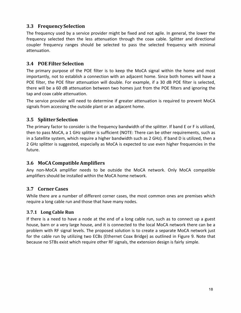
3.7.1 LongCableRunIf there isaneedtohaveanodeat theendofa longcablerun,suchastoconnectupaguesthouse,barnoraverylargehouse,anditisconnectedtothelocalMoCAnetworktherecanbeaproblemwithRFsignal levels.TheproposedsolutionistocreateaseparateMoCAnetworkjustforthecablerunbyutilizingtwoECBs(EthernetCoaxBridge)asoutlined inFigure9.NotethatbecausenoSTBsexistwhichrequireotherRFsignals,theextensiondesignisfairlysimple.
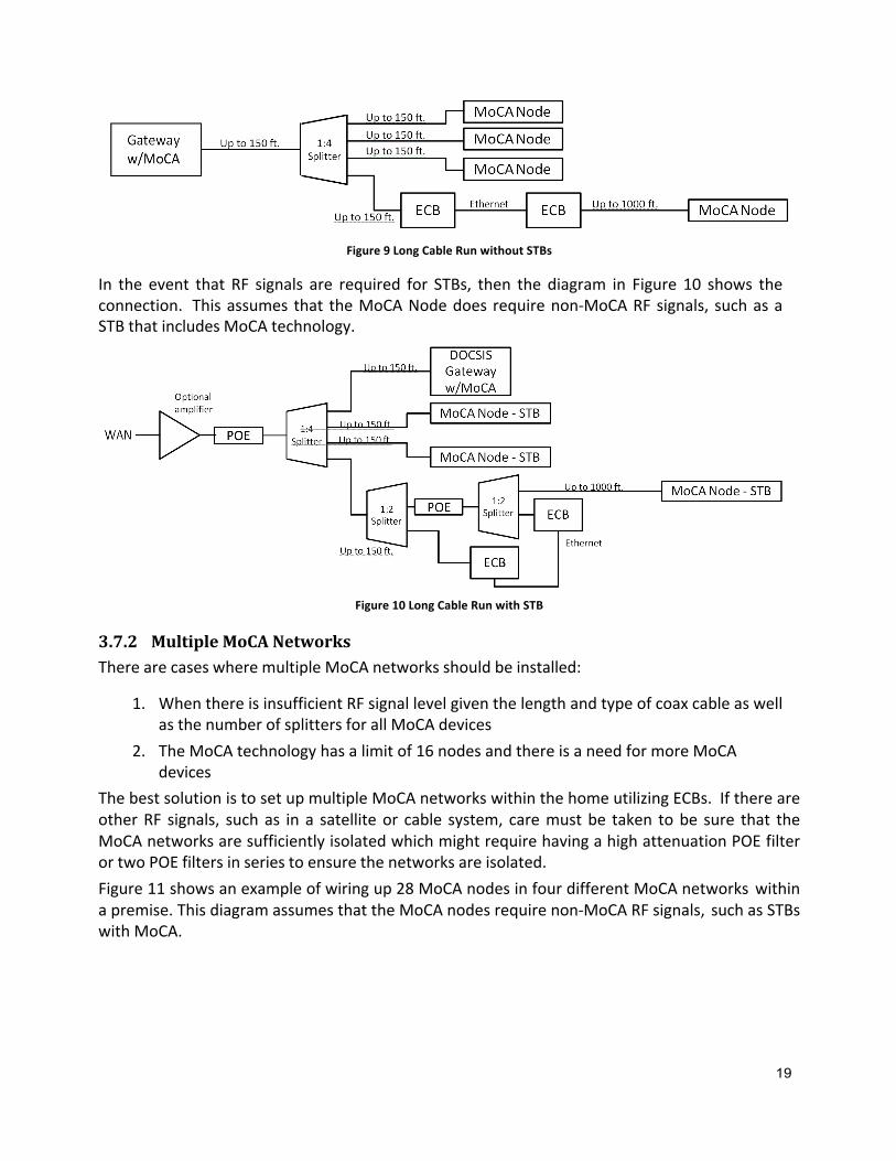
Figure9LongCableRunwithoutSTBs
In the event that RF signals are required for STBs, then the diagram in Figure 10 shows theconnection. Thisassumes that theMoCANodedoesrequirenon-MoCARFsignals, suchasaSTBthatincludesMoCAtechnology.
Figure10LongCableRunwithSTB
3.7.2 MultipleMoCANetworksTherearecaseswheremultipleMoCAnetworksshouldbeinstalled:
1. WhenthereisinsufficientRFsignallevelgiventhelengthandtypeofcoaxcableaswellasthenumberofsplittersforallMoCAdevices
2. TheMoCAtechnologyhasalimitof16nodesandthereisaneedformoreMoCAdevices
ThebestsolutionistosetupmultipleMoCAnetworkswithinthehomeutilizingECBs. IfthereareotherRF signals, suchas in a satelliteor cable system, caremustbe taken tobe sure that theMoCAnetworksaresufficientlyisolatedwhichmightrequirehavingahighattenuationPOEfilterortwoPOEfiltersinseriestoensurethenetworksareisolated.Figure11showsanexampleofwiringup28MoCAnodesinfourdifferentMoCAnetworkswithinapremise.ThisdiagramassumesthattheMoCAnodesrequirenon-MoCARFsignals, suchasSTBswithMoCA.

Figure11ManyNodes

Figure12isanexampleofwiringmultiplenodesiftherearenootherRFsignals,suchaswhentherearenoSTBs.
Figure12ManyNodeswithoutSTBs
4 TroubleshootingMostMoCAinstallshavenoissuesthatcanbetieddirectlybacktoMoCAtechnology.Ifthereisan issue, it’s likelytobefound inthehomewiringorsomeotherpieceofequipmentsuchasahiddenamplifier.Thissectionprovidesyouwithtipsfortroubleshootingthosesituations.MoCAtechnologyreliesontheimpedancequalityofthecoaxialhomedropsystemandthehostor terminal devices. Improper home network configurations can negatively impact a MoCAnetwork. ResolvingimpairmentsiseasysolongasyouknowwhattolookforinaMoCAnetwork.ThebestmethodoftroubleshootingaMoCAnetworkistofirstusetheMoCAdevicediagnosticsandreadthePHYrateoftheMoCAdevices.
IfthePHYrateisnotpresent(i.e.deviceisnotconnectingtotheMoCAnetwork),theneithertheconnection isopenorthere is toomuchattenuation.Severe impedanceandmismatches in thecoaxialdropsystemcannegativelyimpactaMoCAnetwork.Stepstofollow:
1. Verifythecontinuityofthecoaxcable2. EnsurethattheFconnectorsareproperlyinstalled(e.g.centerconductorisofsufficient
length)3. Ensurethatsplittersarecorrectlyinstalled4. EnsurethatPOEfiltersarecorrectlyinstalled
After verifying the home is configured correctly, start by looking for cable and connectordeficiencies in the network. Remember, once two MoCA technology enabled devices areconnectedtogether,aMoCAnetworkinthehomeisformed.IfthePHYrateispresentbutlowthenthereismostlikelytoomuchattenuationinthenetwork.Anyextremebreaks,bends,orgapsinthenetworkwillcauseimpedancechanges.AlowPHYratecanoccurbecauseofa splitterbeing incorrectly installed,badconnection,or that thenetworkneedstobesegmented(seesection3.7.2).Impendencemismatchcouldbein-betweenanyoftheMoCAenableddevicesInterferenceproblemscanalsooccurifthewrongbandisused.Checkwiththeserviceprovidertodeterminewhichbandshouldbeused.(seesection2.1).ThekeyistoreviewthoseconnectedMoCAtechnologyenableddeviceswiththelowestPHYRatesignalpath.ThedeviceswiththelowestPHYRatepathscanbelocatedusingtheMoCAenableddevice’sdiagnostictools.Stepstofollow:
1. Ensurethatsplittersarecorrectlyinstalled2. EnsurethatFconnectorsareproperlyinstalledandtight3. EnsurethatPOEfiltersareproperlyinstalled4. IfRG-59coaxcableisutilized,upgradetoRG-6
CalculatetheattenuationtodeterminewhetherthenetworkneedstobesegmentedTroubleshootingTips
1. A POE Filter must be present and installed before any Splitter or Unity Gain Amplifier(UGA)set-ups;ascloseaspossibletothecentrallylocatedSplitter,UGA,orGroundBlock.
2. Configure coaxial network (Splitters and UGAs) in a centrally located network. Always,minimizedaisychainedandloop-systemsplitterconfigurationswhenatallpossible.
3. BegintroubleshootingatDeviceswiththepoorestPHYRatesignalpaths.NotethatdeviceshaveIn/Outpaths.
5 Appendix
5.1 Power–dBmtodBmVConversion
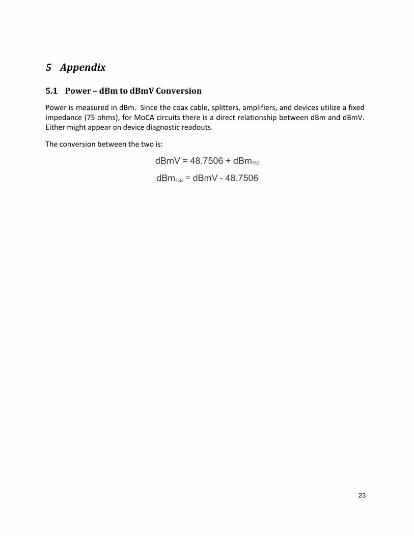
PowerismeasuredindBm. Sincethecoaxcable,splitters,amplifiers,anddevicesutilizeafixedimpedance(75ohms),forMoCAcircuitsthereisadirectrelationshipbetweendBmanddBmV.Eithermightappearondevicediagnosticreadouts.
Theconversionbetweenthetwois:
dBmV = 48.7506 + dBm75Ω
dBm75Ω = dBmV - 48.7506
ONLINE
www.mocalliance.orgMoCAinYourHouse.comMoCA4Installers.com
SOCIAL
facebook.com/MoCAlliance
twitter.com/MoCAlliance
linkedin.com/company/846994
youtube.com/MoCAlliance
CONTAC T
Rob GelphmanVice President Marketing and Member Relations [email protected]
Roberta SilversteinManaging [email protected]