fine temperature measurement and fabrication of on …
TRANSCRIPT
1 Copyright © 2013 by ASME
Proceedings of the ASME 2013 Micro/Nanoscale Heat & Mass Transfer International Conference MNHMT2013
December 11-14, 2013, Hong Kong, China
MNHMT2013-22003
FINE TEMPERATURE MEASUREMENT AND FABRICATION OF ON-CHIP WHISPERING-GALLERY MODE MICRO-SENSORS
Matthew Frenkel Department of Mechanical and
Aerospace Engineering Rutgers University
Piscataway, New Jersey 08854
Marlon Avellan Department of Mechanical and
Aerospace Engineering Rutgers University
Piscataway, New Jersey 08854
Zhixiong Guo1 Department of Mechanical and
Aerospace Engineering Rutgers University
Piscataway, New Jersey 08854
1 Address all correspondence to this author.
ABSTRACT
Whispering-Gallery mode based optical micro-devices have been demonstrated to have extremely high sensitivity to changes in local temperature owing to their high quality factors and frequency-based measurements. In this paper, we first examine different fabrication techniques for integrating whispering-gallery mode sensors directly onto heating components to realize on-chip in-situ dynamic temperature measurements and monitoring. The merits and drawbacks of each fabrication technique are discussed. Then, the capability of the fabricated on-chip micro-sensors to perform precise real-time thermal measurements was tested, and the findings are discussed. Finally, the advantages of such on-chip sensors are established through heat transfer analysis.
INTRODUCTION
The use of optical whispering-gallery mode (WGM)
resonators as sensing devices has been a highly active area of research over the past two decades [1-6]. A WGM sensor consists of near-field optical light coupled into a dielectric micro-device that must have a circular geometry to support the total internal reflection (TIR) of the coupled light around its surface. Commonly, spherical, cylindrical, and toroidal geometries are used. If the path length of the TIR light is equal to an integer number of the coupled light’s wavelength then the resonance criterion is met and the dielectric device will act as a WGM resonator. The nature of this resonance criterion and the intrinsic high quality (Q-factor) make WGM resonator a highly attractive sensing choice.
The resonance criterion of the WGM sensor is dependent on both the diameter of the resonator as well the
index of refraction of the resonator material, thus, any environmental effects that cause a change in either of these resonator properties or interfere with the evanescent field will result in shifts in the resonance frequencies. The inherent high Q-factor of the resonators and the capabilities of modern data acquisition systems allow for extremely high precision when monitoring shifts in the resonance wavelengths or frequencies. The Q-factor of the resonator is the ratio of energy stored in a WGM to the energy dissipation rate of the resonator. The quality of the resonator depends on both material property and the fabrication technique used. Sensors with polydimethylsiloxane (PDMS) layers have been demonstrated with Q’s of 105 – 106 [7,8], fused silica based resonators have been found with Q’s of 107 - 1010 [3,9], and other materials such as calcium fluoride have been fabricated with Q’s of 1011 [10].
There are demonstrations in literature of sensors designed for molecular [4,6,11], temperature [9], pressure [12], and gas sensing [13]. In all these cases, the WGM sensor demonstrates very high resolution. In the above examples, the WGM resonator is used as an independent component that exists within the larger environment. Recent work [8] demonstrated that a WGM resonator can be directly fabricated onto an already existing component. It is the aim of this paper to examine different techniques that can be used to fabricate WGM annular resonators directly onto a slender cylinder and if the coated resonators can be used to monitor, in real time, changes in the cylinder’s temperature.
FABRICATION The first method utilized in our experiment was briefly discussed in reference [8]. In this technique, PDMS was used to form the WGM resonator and a 127-micron diameter nichrome

2 Copyright © 2013 by ASME
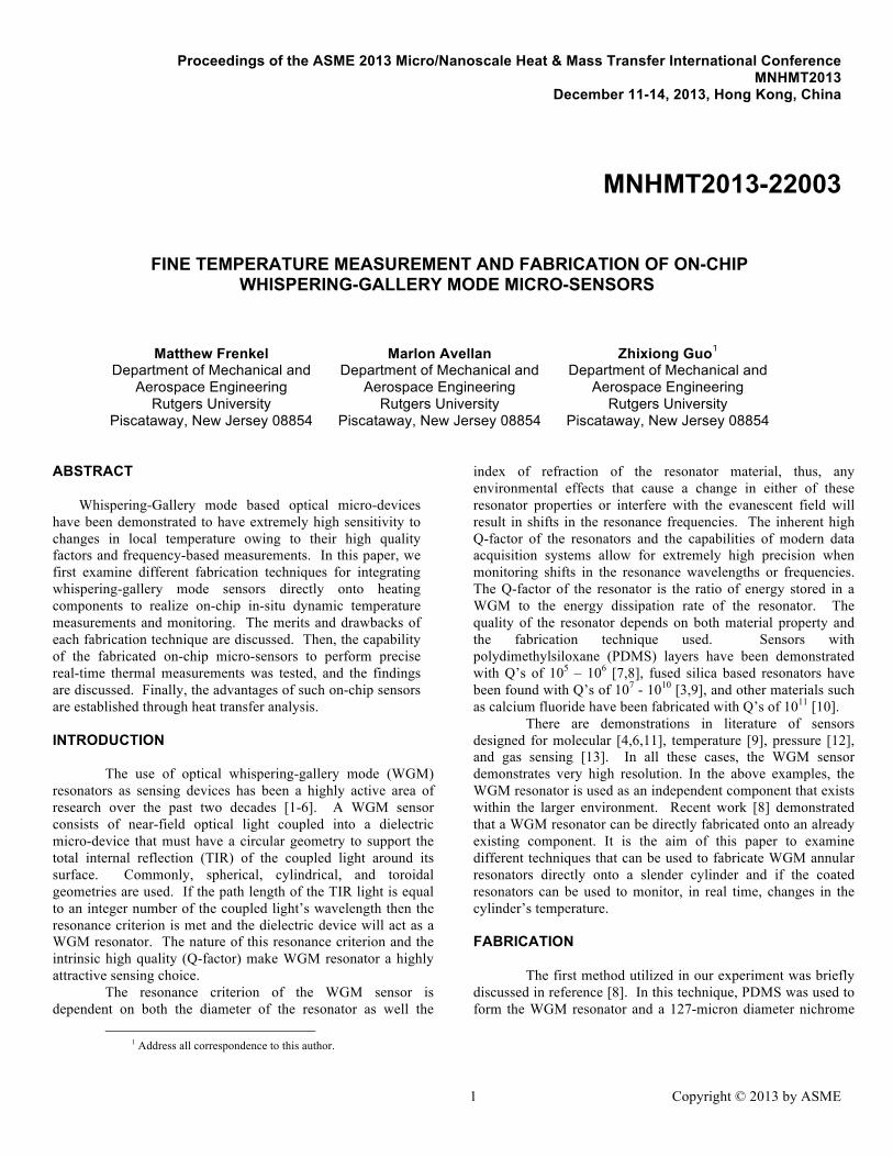
wire was chosen as the slender cylinder of an electronic chip in operation. PDMS was mixed in a 10:1 weight ratio. After mixing, the PDMS was degassed in a vacuum chamber. The nichrome wire was suspended, in tension, vertically. The wire was then attached in series to a DC power supply so that it could be directly heated. PDMS was placed on the wire using the stripped and cleaned end of an optical fiber. Dipping the optical fiber into the PDMS and quickly removing it forms small droplets at the end of the fiber. These droplets were then placed directly onto the wire. Fig. 1A shows a diagram of the setup for fabrication. By using this technique, droplets with diameters from ~200 µm to ~1000 µm were formed. After the droplets were placed on the wire, the power supply was turned on so that approximately 300mA were sent through the nichrome causing the wire to heat up, curing the PDMS. It was found that droplets below 500 µm were cured in place, whereas droplets >500 µm would slowly slide down the wire leaving a thin PDMS layer, approximately 10-15 µm, surrounding the wire. This process could be repeated multiple times to build up the thickness of the shell. Using this technique, we were able to produce ellipsoid shells with outer diameters between 200 – 500 µm and cylindrical annuli with thicknesses between 10 – 100 µm. Figs. 2A and 2B show examples of these two geometries.
In efforts to form thinner shells, a second method was tested for fabricating PDMS layers on a nichrome wire. The PDMS used here was prepared in the same manner as before. In this technique, the nichrome wire is again suspended, in tension, vertically, but instead of being attached to a power supply; it is attached to a DC motor. Droplets are placed on the wire as before, but running an electrical current through the wire is no longer used to cure them. Instead the system is externally heated to 50 - 60°C by enclosing it in a greenhouse chamber and using a heating lamp. While enclosed in this chamber, the DC motor is used to spin the nichrome wire about its axis at ~75RPM. Fig. 1B shows a diagram of this setup. The wire is left rotating in the greenhouse chamber for several hours to ensure that the beads have fully cured.
During the curing process, like in method one, the larger beads slid down the wire. However, they did not leave a cylindrical annulus in their wake as in method one. Instead, a number of small ellipsoid shells were found along the length of the wire. These shells have for the most part, very small variation in their diameters; shells next to each other had diameters within 5 µm. Additionally, these ellipsoid shells were fabricated with smaller outer diameters than what was achieved in method one. Outer diameters of ~150 µm could be produced with method two. There was also a thin layer of PDMS, ~5 µm connecting the two consecutives shells. A representative shell is shown in Fig. 2C. The major drawback of this method was the difficulty in aligning the center of rotation with the axis of the wire in our lab-made facility.
Fused silica resonators have an intrinsically higher quality factor than that of PDMS based resonators, and so, efforts were made to develop methods for forming a fused silica layer onto a wire. The first technique attempted was to directly
Figure 1. FOUR DIFFERENT TECHNIQUES USED FOR THE FABRICATION OF MICRO-RESONATORS A) METHOD ONE: INTERNALLY HEATED PDMS B) METHOD TWO: EXTERNALLY HEATED PDMS WITH SPINNING C) METHOD THREE: HEAT AND PULL OF SILICA GLASS. D-1) METHOD FOUR: GLASS FIBER ATTACHED TO WIRE. D-2) GLASS BEAD FORMED UNDER SURFACE TENSION
fuse silica based glass onto a wire. The wire was suspended horizontally and a piece of hollow silica tubing (borosilicate glass) was placed around the wire. An oxygen/hydrogen torch was used to heat one end of the glass tubing to its softening point. While softened, the glass forms around the inner wire. By gently pulling the heated tubing, a cylindrical annulus can be formed around the inner wire. Fig. 1C shows a diagram of this method. The nichrome wire failed within the environment heated by the torch, therefore, we used a 255 µm diameter tungsten wire.
This method proved to be very difficult to control. Inconsistence in the pulling rate of the glass tubing and the flame temperature resulted in large variations in the coatings thickness along the wire. At the thinnest points, coatings had a thickness of 20 µm, but thicknesses >100 µm were also found. Fig. 2D
3 Copyright © 2013 by ASME
Figure 2. IMAGES OF THE FABRICATED RESONATORS A) ELLIPSOID SHELL: METHOD ONE, B) CYLINDRICAL ANNULUS:
METHOD ONE, C) ELLOPSOID SHELL: METHOD TWO, D) CYLINDRICAL ANNULUS: METHOD THREE. NOT PICTURED) METHOD FOUR - BEADS LOOK THE SAME AS IN METHODS ONE AND TWO UNDER OPTICAL MICROSCOPE.
shows a coated tungsten wire. Another major drawback of this method was the high temperatures required to soften the glass. These high temperatures greatly limit the available materials that our sensors could be fabricated onto. Lastly, the resonators fabricated onto the tungsten were found to be very brittle. If the wire was bent, the silica coating would facture or shatter off, making it useless as a WGM resonator. Maker et. al. [14] demonstrated doped silica coatings with 350nm thickness around a silica micro-torroid using a sol-gel procedure. The sol-gel procedure is an attractive method for fabricating thin films because it is a chemical process, and although there is an annealing phase, it requires lower temperatures than direct fusing of silica. We have made some preliminary tests in efforts to utilize this method for creating micrometer coatings. To date our coatings, after the annealing phase, are fractured and cannot support WGMs. We believe this is caused by the stresses developed in the coating due to the mismatched thermal expansions of the silica and our wires. A fourth overall method, and second method for fusing silica based glass beads, was developed where the glass was first pulled into fibers before being fused to the chip element. Fibers were created from commercially obtained BK-7, borosilicate, and flint glass. The glass was placed inside a crucible where it was heated and then pulled to form a thin fiber. Each glass was heated and pulled in separate crucibles to avoid cross
contamination. A 127 µm wire was then positioned in the same manner as method one. For this method, the power supply is turned on so that approximately 1.5A of current is sent through the wire, causing it to reach temperatures > 1000 °C. The glass fiber is then placed in contact with the hot wire and pulled away leaving a small glass taper attached to the wire, as seen in Fig. 1D-1. In the case of both the BK-7 and flint glass if the current continues to run through the wire the attached glass taper will melt and surface tension will form a bead around the wire as seen in Fig. 1D-2, but there is not enough heat provided by the wire to melt the borosilicate taper. Beads formed by this method are not shown in Fig. 2 because under the optical microscope they appear the same as beads fabricated in methods one and two. TESTING AND DISCUSSION
Upon fabrication, tests were run to determine the
quality of the WGM resonators. The WGM sensors were placed in contact with a tapered optical fiber, used to couple light into the resonator. A 1516 nm DFB laser was delivered into the fiber taper at one end. This wavelength of the laser can be controlled using a function generator and a laser controller. The other end of the tapered fiber outputted to a photodetector.

4 Copyright © 2013 by ASME
Figure 3. SCHEMATIC OF EXPERIMENTAL SETUP
This photodetector was attached to a digital oscilloscope allowing us to read the spectrum of the WGM resonator. A dip in the laser output seen by the oscilloscope indicates a resonance frequency. Fig. 3 is a schematic of the experimental setup. A complete description of this setup can be found in reference 8. The Q-factor of the resonator can be determined by examining the dips in the recorded spectrum, where Q = λ/Δλ [10]. Fig. 4 shows representative spectra from the resonators produced via each of the above-mentioned four fabrication methods. Method one demonstrated a quality factor of PDMS resonators to the level of 105~106. The ellipsoid shells consistently had better Q-factors than the cylindrical annuli because the diameter of the shells is larger.
It was thought that by using a spin coating technique, we could create a more uniform PDMS surface that would increase the Q-factor. Although we were able to fabricate thinner coatings via this method, the Q-factors were consistent with those seen in method one. Ellipsoid shells with diameters of ~150 µm supported WGMs, but the Q-factors achieved were not high. Since PDMS was unable to provide extremely high Q-factors with small thickness, we made efforts to fabricate fused silica resonators.
In terms of Q-factor, the silica resonators fabricated, via method three, worked very well. The thinnest coating thickness as described before demonstrated Q-factors of high 105, and thicker resonators demonstrate Q-factors of 106. In previous work of our group [9], Q-factor greater than 107 was achieved. We developed method four in hopes it would allow for better consistence and finer control of resonator diameters than we could achieve with method three, while still maintaining the higher Q-factor of fused glass resonators. While our control was greatly improved, the Q-factor suffered. BK-7 glass never provided WGM resonance and flint glass provided WGMs with low 105 Q-factors. We are currently investigating how to improve the Q-factor of resonators formed with this method.
PDMS provides the great advantage of not requiring high temperature for curing. Because of this, resonators can be fabricated easily around different devices, either by directly placing a PDMS droplet, or by using a spin coating technique. Unfortunately, when a thin coating layer is required for precision measurements, as can be the case for temperature monitoring [8], PDMS does not exhibit a high enough Q-factor to act as a ultrafine sensor. Fused silica, on the other hand, demonstrates Q-factors high enough to support 1-10 mK resolution even at thin coating thickness. Nevertheless, the fabrication techniques for fusing silica directly onto an area of interest require very high temperatures and thus greatly limit its applications.
Figure 4. SPECTRA COLLECTED FROM WGM RESONATORS (TOP) METHOD ONE: 242 µm RESONATOR, (MIDDLE) METHOD TWO: ~400 µm RESONATOR, (BOTTOM) METHOD THREE: ~300 µm RESONATOR. METHOD FOUR: FLINT GLASS 400 µm.

5 Copyright © 2013 by ASME
Resonators fabricated via methods one, three, and four were also tested directly as temperature sensors. Method two was neglected in these experiments because it provided no significant improvements from method one. In order to test the resonators as temperature sensors, the coated wires were placed inside an externally heated chamber. A thermocouple was placed in contact with the test wire and within a several millimeters of the resonator. The temperature inside the chamber was increased 10°C from room temperature by a rate of 1°C every 3-5 minutes. The temperature was increased at this slow rate to ensure that both the resonator and the thermocouple would be in thermal equilibrium. Data was recorded simultaneously from the resonator and the thermocouple every minute. Each recorded data point consists of 10 waveforms collected with a rate of 100 Hz and averaged together. Fig. 5 graphs the relationship between resonance frequencies shifts and changes in the temperature, and Table 1 lists the values of the resonators sensitivities as well as the linear correlation coefficient.
Figure 5. TEMPERATURE RISE VS. WAVELENGTH SHIFT FOR VARIOUS COATED RESONATORS.
Both Fig 5. and Table 1 demonstrates that the sensitivity of the PDMS sensor depends on the thickness of the coating. Eq. (1) represents the current theory used to find the sensitivity of a WGM resonator:
€
dλdT
= λ01ndndT
+1DdDdT
#
$ %
&
' ( = λ0
1nα + β
#
$ %
&
' ( (1)
Here T is the temperature n is the refractive index, D is the resonator diameter. α and β are the thermal optical and thermal expansion coefficients of the resonator respectively, and λ is the wavelength of laser light used. In order to address the composite nature of our device, effective thermal optical and thermal expansion coefficients need to be considered.
An argument is put forth in [8] demonstrating that the thermal optical coefficient of the coating material can be used in Eq. 2. This argument is based on the thicknesses of the coating layers as well as the optical properties of the core
wire. To find the effective thermal expansion coefficient, a model is adopted from Tummala and Friendberg [15]:
€
βeff = β2 −V1(1+υ2) 2E2
[(1+υ2) 2E2]+ [(1− 2υ1) /E1](β2 − β1) (2)
In this equation, subscripts, 1, represent the core material and subscript, 2, represent the coated layer. E and υ are the Young’s modulus and Poisson ratio respectively. V is the volume fraction of the core inside the coated layer. By replacing β in Eq. (1) with βeff found in Eq. (2), we are able to explain the experimental behavior seen in Fig. 5. The blue and red shifts found depending on the PDMS thickness, as well as, the asymptotic behavior of the sensitivity, are both accounted for through definition of βeff.
It is worth noting that the sensitivity of a pure silica resonator of similar diameter was found experimentally to be 10.82 pm/K at room temperature and analytically to be approximately 9.5 pm/K [9,16]. Our sensitivity was found to be 10.35 pm/K. Our sensitivity is between the experimental and analytical sensitivities put forth in these papers. We anticipate that more testing well demonstrate the same diameter dependence for fused silica as was seen with the PDMS coatings.
Figure 6. DIRECT HEATING AND COOLING OF A COATED WIRE AT THREE DIFFERENT CURRENTS (I = 0.03 A, I = 0.04 A, I = 0.05 A): A) HEATING CURVES, B) COOLING CURVES

6 Copyright © 2013 by ASME
Table 1. THE SENSITIVITY OF FOUR DIFFERENT DIAMETER MICRO-RESONATORS, ONE PDMS CYLINDRICAL ANNULUS, TWO PDMS SPHERICAL SHELLS, AND ONE SILICA CYLINDRICAL ANNULUS.
Resonator Diameter (µm) Sensitivity (nm/K) Correlation Coefficient
172 (PDMS cylindrical annulus) -0.0657 ± 0.0036 0.999 81 345 (PDMS spherical shell) 0.0874 ± 0.0048 0.999 94
368 (Silica cylindrical annulus) 0.01035 ± 0.0057 0.998 33 400 (Flint Glass spherical shell) 0.0119 ± 0.0057 0.996 62
512 (PDMS spherical shell) 0.1078 ± 0.0059 0.999 79
Additionally, it can be observed from both Fig. 5 and Table 1, that when comparing PDMS and fused glass based resonators of similar sizes the PDMS resonator provides a sensitivity of almost an order of magnitude larger than the glass counterpart. This can be explained through Eq. 1. The thermal expansion and thermal optical coefficients of PDMS are approximately 2 orders of magnitude larger than those of the glass used in this paper, which accounts for the difference in sensitivity.
Finally, using the calibrations found by externally heating the resonator, we can test its ability to directly measure temperature changes of the core material. We raise the temperature of the core material via joule heating. Running small currents through the core keeps our temperatures within the bounds of our calibrations. To date, we have only been able to collect data on sensors fabricated via method one (PDMS on nichrome). In this experiment, data is simultaneously collected from both our resonator and our thermocouple every 2-3 seconds. This data collection rate is fast enough to allow us to monitor changes in the wires temperature, but slow enough to ensure our sensors are responding properly. The governing equation for our coated system is as follows:
€
π4D12ρ1Cp1 + D2
2 −D12( )ρ2Cp2[ ] dTdt =
4I2σ e
πD12 −πD2h T −T∞( )
(3) here I is the current within the core, σe is the electrical resistivity of the core, h is the heat transfer coefficient of
convection, T∞ is the ambient air temperature, t is time, and ρ and Cp are the density and specific heat respectively. Eq. (3) can be solved to find the temperature of the wire as a function of time. It should be noted that the heat transfer coefficient of convection is found using Churchill and Chu’s correlation for a horizontal cylinder [17]. Fig. 6 plots the data collected for both heating and cooling of the wire. To cool the wires, the current was removed and they were allowed to relax in the ambient air.
Results from Fig. 6 show that the WGM sensors are able to perform accurate temperature monitoring for the heating and cooling of the wire. Additionally, we can see that the WGM resonators outperformed the thermocouple in these experiments. We attribute the superior performance of the WGM sensor to that fact that when using high gauge wires it
is very difficult to ensure perfect contact between the thermocouple and the wire. In this paper, we have demonstrated several different techniques for the fabrication of micro-annular resonators directly onto an element of interest. We have shown, experimentally, how each technique affects the Q-factor. We have demonstrated that these micro-resonators can be used both to detect environmental temperature changes as well temperature changes caused by the direct heating of the element they have been fabricated onto.
ACNOWLEDGMENTS This material is based upon work supported by the National Science Foundation under Grant No. CBET- 1067141. We would also like to thank John Petrowski and Joseph Vanderveer for their assistance in designing and machining different experimental components, and Professor Lisa Klein for her assistance with the sol-gel technique.
REFERENCES [1] Serpenguzer, A., Arnold, S., and Griffel, G., 1995, “Excitation of resonances of microspheres on an optical fiber,” Opt. Lett., 20, pp. 654-656. [2] Knight, J.C., Dubreuil, N., Sandoghdar, V., Hare, J., Lefevre-Seguin, V., Raimond, J.M., and Haroche, S., 1995, “ Mapping whispering-gallery modes in microshperes with a near-field probe,” Opt. Lett., 20, pp. 1515-1517 [3] Gorodtsky, M., Savchenkov, A., and Ilchenko, V., 1996, “Ultimate Q of optical microspehere resonators,” Opt. Lett., 21, pp. 453-455. [4] Arnold, S., Khoshsima, M., Teraoka, I., Holler, S., and Vollmer, F., 2003, “ Shift of whispering-gallery modes in microspheres by protein adsorption,” Opt. Lett., 28, pp. 272-274. [5] Vahala, K., 2003 “Optical microcavities,” Nature, 424, pp. 839-846. [6] Vollmer, F, and Arnold, S., 2008, “Whispering-gallery- mode biosensing: label-free detection down to single molecules,” Nature Methods 5, pp. 591 - 596. [7] Li, B. B., Wang, Q. Y., Xiao, Y. F., Jiang, X. F, Li, Y. Xiao, L., and Cong, Q., 2010, “On chip, high-sensitivity
7 Copyright © 2013 by ASME
thermal sensor based on high-Q polydimethylsiloxane-coated microresonator,” Appl. Phys. Lett. 96, (251109). [8] Frenkel, M., Avellan, M., and Guo, Z., 2013,“Whispering-gallery mode composite sensors for on-chip dynamic temperature monitoring,” Meas. Sci. Tech., 24. (075103). [9] Ma, Q., Rossmann, T., and Guo, Z., 2010, “Whispering-gallery mode silica microsensors for cryogenic to room temperature measurement,” Meas. Sci. Technol. 21, (025310). [10] Savchenkov, A., Matsko, A., Ilchenko, V., and Maleki, L., 2007, “Optical resonators with ten million finesse,” Opt. Express., 15, pp. 6768-6773. [11] Quan, H., and Guo, Z., 2007 “Simulation of single transparent molecule interaction with optical microcavity,” Nanotechnology 18, (375702). [12] Ioppolo, T., Kozhevnikov, M., Stepaniuk, V., Otugen, M., and Sheverev, V., 2008 “Micro-optical force sensor concept based on whispering gallery mode resonators,” App. Opt. 47, pp. 3009-3014. [13] Ma, Q., Huang, L., and Guo, Z., 2010,“Spectral shift response of optical whispering-gallery modes due to water vapor adsorption and desorption,” Meas. Sci. Technol. 21, (115206). [14] Maker, A., Rose, B., and Armani, A., 2012, “Tailoring the behavior of optical microcavities with high refractive index sol-gel coatings,” Opt. Let., 37. pp. 2844-2846. [15] Tummala, R. R., and Friedberg A. L., 1970, “Thermal Expansion of Composite Materials”. J. Appl. Phys. 41, pp. 5104-5107 [16] Ma, Q., Rossmann, T., Guo, Z., 2008, “Temperature sensitivity of silica micro-resonators,” J. Phys. D: Appl. Phys., 41. (245111). [17] Bejan, A., 2004, Convection Heat Transfer, 3rd edn., Wiley, Hoboken, NJ, Chap. 4.