fingersim set - gossenmetrawatt.com€¦ · fingersim set for seculife nibp in ... 7.3 quiescent...
TRANSCRIPT

Operating Manual
FINGERSIM SET for SECULIFE NIBP in Combination with SECULIFE OX1
3-349-631-03 1/5.11

GMC-I Messtechnik GmbH 3
CONTENTS
1 GENERAL WARNINGS AND CAUTIONS........................... 4 2 PURPOSE ........................................................................... 5 3 DESCRIPTION .................................................................... 6 4 THEORY OF OPERATION.................................................. 8 5 CONDITIONS THAT AFFECT USE................................... 11
5.1 Ambient Temperature............................................... 11 5.2 Movement Artifact..................................................... 13 5.3 Sensor Alignment and Position ................................ 13
6 CHECK OUT...................................................................... 14 7 OPERATING INSTRUCTIONS.......................................... 14
7.1 Insert the FingerSim™ into the Holder ..................... 14 7.2 Attach the Sensor..................................................... 15 7.3 Quiescent Test ......................................................... 16 7.4 Oxygen Saturation Test............................................ 16 7.5 Pulse Rate Test........................................................ 17 7.6 Pulse Amplitude Test................................................ 17
8 SPECIFICATIONS............................................................. 18 8.1 FingerSimTM ............................................................. 18 8.2 B. Holder .................................................................. 18
9 SERVICE AND MAINTENANCE ....................................... 19 10 WARRANTY ...................................................................... 19 11 ACCESSORIES................................................................. 20 12 TROUBLE SHOOTING CHART......................................... 21 FIGURES
Figure 1 Seculife FingerSim™.................................................. 6 Figure 2 Seculife Replacement Holder ..................................... 7 Figure 3 80 % SpO2 Absorption Spectrum ............................. 9 Figure 4 90 % SpO2 Absorption Spectrum ............................. 9 Figure 5 97 % SpO2 Absorption Spectrum ........................... 10 Figure 6 80 % SpO2 Temperature Dependence..................... 11 Figure 7 90 % SpO2 Temperature Dependence..................... 12 Figure 8 97 % SpO2 Temperature Dependence..................... 12 Figure 9 Sensor Cable Routing Through Holder .................... 13 Figure 10 Positioning the FingerSim™ in the Holder................ 15 Figure 11 Sensor Cable Routing Through Holder .................... 16 Figure 12 Generating a Simulated Pulse.................................. 17

4 GMC-I Messtechnik GmbH
1 GENERAL WARNINGS AND CAUTIONS CONTRAINDICATION:
Do not use with reflectance or ear clip sensors. Use only with transmittance type, finger or toe sensors.
WARNING: FingerSimsTM are fragile and must be handled with care, they contain glass.
CAUTION: Federal law restricts this device to sale by or on the order of a physician.
CAUTION: The movement of the FingerSimTM relative to the oximeter sensor may cause erroneous pulse rate and/or oxygen saturation readings. Use the FingerSimTM Holder to facilitate pulse generation without introducing FingerSim™ movement relative to the oximeter sensor.
CAUTION: Do not use a FingerSimTM that is cracked or leaking fluid.
CAUTION: Avoid extended exposure to sunlight. CAUTION: The SpO2 simulation by the FingerSimTM is
temperature dependent. See Charts 6, 7 and 8 for the appropriate adjustment. Allow at least one-hour stabilization at room temperature before using.
CAUTION: Do not store the FingerSimTM outside the recommended Long Term Storage Temperature range (32 °F - 104 °F / 0 °C - 40 °C). NOTE: Temperatures outside this range for short duration are acceptable (for example during shipping).
CAUTION: When testing flexible sensors, ensure the emitter and detector are vertically aligned on opposite sides of the FingerSimTM
CAUTION: Do not use beyond the calibration date. CAUTION: No test system can simulate all possible operating
conditions a pulse oximeter may encounter. Use the FingerSimTM as an adjunct to other indications to determine proper pulse oximeter operation.
CAUTION: Improper insertion of the FingerSimTM into the Holder can cause breakage. Insert the Phantom as shown in Figure 7

GMC-I Messtechnik GmbH 5
2 PURPOSE The FingerSimTM Pulse Oximeter Test System enables the healthcare professional to evaluate pulse oximeter and sensor function at three simulated light absorption conditions. These absorption conditions are set to simulate a typical finger at nominally 97 %, 90 %, and 80 % SpO2 levels. In addition, a pulse oximeter’s response to various pulse amplitudes and rates can be simulated. Before the availability of the Seculife FingerSimTM, pulse oximetry systems (oximeter plus sensor) were not easily tested. The oximeter’s measurement of the small pulsatile blood component and the interrelationship of the oximeter calibration curve with the light emitting characteristics of the sensor made a true oximeter system tester difficult to conceive. The Seculife FingerSimTM System, when used as an adjunct to other indicators, aids the healthcare professional in assessing performance of both oximeter and sensor. CONTRAINDICATION:
Do not use with reflectance or ear clip sensors. Use
only with transmittance type, finger or toe sensors.
CAUTION: No test system can simulate all possible operating
conditions a pulse oximeter may encounter. Use the FingerSimTM as an adjunct to other indicators to determine proper pulse oximeter operation.

6 GMC-I Messtechnik GmbH
3 DESCRIPTION The Seculife FingerSimTM system provides a rapid, inexpensive and convenient means of assessing the function of the entire pulse oximeter system including the oximeter sensor. A set of three FingerSimsTM are included in each kit. Each of the three FingerSimsTM contain a fluid with precisely controlled light absorption characteristics sandwiched between two glass slides. The concentration of the substances in the three mixtures allow the FingerSim™ to mimic the light absorbing qualities of arterial blood as measured by an oximeter at different oxygen saturation values (nominally 97 %, 90 %, and 80 %). The 97 %, 90 %, and 80 % FingerSimsTM are easily identified by the color coded end caps (Red - 97 %, Blue - 90 %, and Black - 80 %). Squeezing the colored coded flat end will produce a pulsatile movement of the solution. This pulsation is detected as a pulse by the oximeter system being tested, and thus allows the oximeter to calculate and display an SpO2
value which corresponds to the fixed light absorbing characteristics of the particular FingerSimTM being used.
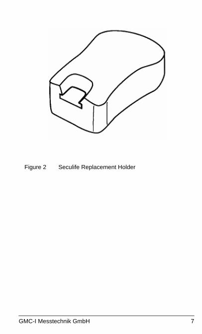
Figure 1 Seculife FingerSim™ A holder is provided to stabilize the FingerSim™ while the pulsatile movement of the internal solution is generated.
GMC-I Messtechnik GmbH 7
Figure 2 Seculife Replacement Holder

8 GMC-I Messtechnik GmbH
4 THEORY OF OPERATION The principle of differential light absorption is used by a pulse oximeter to determine the oxygen saturation of arterial blood (SpO2). Red light and infrared light are differentially absorbed by oxygenated and deoxygenated hemoglobin. The pulse oximeter has a sensor with light emitting diodes (LEDs) that provides these wavelengths of light for transmittance through a measurement site, usually a finger. Based on the relative absorption of these two wavelengths of light at the measurement site, the pulse oximeter determines the relative amount of oxygenated and deoxygenated hemoglobin, which is calculated as SpO2. In order to make this calculation independent of skin color, finger size, etc., the pulse oximeter uses only the time varying light absorption component generated by the patient’s pulse. In addition, the pulse oximeter uses the period of pulsation to measure the pulse rate. The FingerSim™ absorbs light very much like a human finger. The overall red and infrared light absorption of the FingerSim™ approximates the overall light absorption of a typical finger. In addition, the red and infrared photo spectrometric light absorption of the inner solution approximates arterial blood as seen by the oximeter at 80 %, 90 % and 97 % oxygen saturation levels (see Figures 3, 4, and 5). Minor SpO2 variations will be seen between oximeter manufacturers because standards correlating red and infrared light absorption to oxygen saturation in pulse oximetry are not available. Each manufacturer has developed its own correlation and inevitably some differences have developed (see “Health Devices” June 1989). In addition, minor SpO2 variations between sensors will be observed due to the fact that red and infrared emitting light sources vary slightly between sensors. The FingerSim™ enables the healthcare professional to repeatedly test and evaluate the pulse oximeter system (oximeter and sensor) under controlled light absorption conditions.
GMC-I Messtechnik GmbH 9
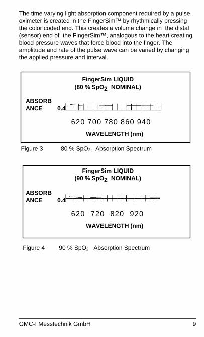
The time varying light absorption component required by a pulse oximeter is created in the FingerSim™ by rhythmically pressing the color coded end. This creates a volume change in the distal (sensor) end of the FingerSim™, analogous to the heart creating blood pressure waves that force blood into the finger. The amplitude and rate of the pulse wave can be varied by changing the applied pressure and interval.
FingerSim LIQUID (80 % SpO2 NOMINAL)
ABSORB ANCE 0.4
620 700 780 860 940
WAVELENGTH (nm)
Figure 3 80 % SpO2 Absorption Spectrum
FingerSim LIQUID (90 % SpO2 NOMINAL)
ABSORB ANCE 0.4
620 720 820 920
WAVELENGTH (nm)
Figure 4 90 % SpO2 Absorption Spectrum

10 GMC-I Messtechnik GmbH
FingerSim LIQUID (97 % SpO2 NOMINAL)
ABSORB ANCE 0.4
620 720 820 920
WAVELENGTH (nm)
Figure 5 97 % SpO2 Absorption Spectrum
GMC-I Messtechnik GmbH 11
5 CONDITIONS THAT AFFECT USE
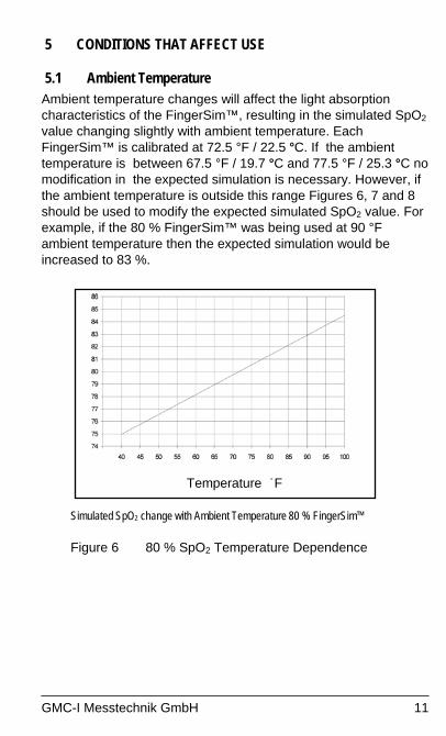
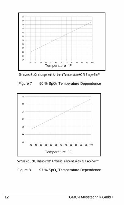
5.1 Ambient Temperature Ambient temperature changes will affect the light absorption characteristics of the FingerSim™, resulting in the simulated SpO2 value changing slightly with ambient temperature. Each FingerSim™ is calibrated at 72.5 °F / 22.5 °C. If the ambient temperature is between 67.5 °F / 19.7 °C and 77.5 °F / 25.3 °C no modification in the expected simulation is necessary. However, if the ambient temperature is outside this range Figures 6, 7 and 8 should be used to modify the expected simulated SpO2 value. For example, if the 80 % FingerSim™ was being used at 90 °F ambient temperature then the expected simulation would be increased to 83 %.
Temperature °F
Simulated SpO2 change with Ambient Temperature 80 % FingerSim™
Figure 6 80 % SpO2 Temperature Dependence
12 GMC-I Messtechnik GmbH
Temperature °F
Simulated SpO2 change with Ambient Temperature 90 % FingerSim™
Figure 7 90 % SpO2 Temperature Dependence
Temperature °F
Simulated SpO2 change with Ambient Temperature 97 % FingerSim™
Figure 8 97 % SpO2 Temperature Dependence
GMC-I Messtechnik GmbH 13
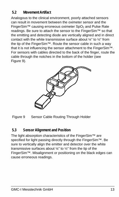
5.2 Movement Artifact Analogous to the clinical environment, poorly attached sensors can result in movement between the oximeter sensor and the FingerSim™ causing erroneous oximeter SpO2 and Pulse Rate readings. Be sure to attach the sensor to the FingerSim™ so that the emitting and detecting diode are vertically aligned and in direct contact with the white transmissive surface about ¼” to ½” from the tip of the FingerSim™. Route the sensor cable in such a way that it is not influencing the sensor attachment to the FingerSim™. For sensors with cables directed to the back of the finger, route the cable through the notches in the bottom of the holder (see Figure 9).
Figure 9 Sensor Cable Routing Through Holder
5.3 Sensor Alignment and Position The light absorption characteristics of the FingerSim™ are specified for light passing directly through the FingerSim™. Be sure to vertically align the emitter and detector over the white transmissive surfaces about ¼” to ½” from the tip of the FingerSim™. Misalignment or positioning on the black edges can cause erroneous readings.
14 GMC-I Messtechnik GmbH
6 CHECK OUT Before each use, visually inspect each FingerSim™ carefully. Do not use the FingerSim™ if the calibration date marked on the color coded handle has elapsed. Do not use the FingerSim™ if it is cracked and/or leaking fluid. CAUTION The SpO2 simulation by the FingerSim™ is
temperature dependent. See Charts 6, 7 and 8 for the appropriate adjustment. Allow at least one hour stabilization at room temperature before using.
7 OPERATING INSTRUCTIONS
7.1 Insert the FingerSim™ into the Holder Carefully insert the short, flat, color coded end of the FingerSim™ into the slot provided at one end of the FingerSim™ Holder. Grasp the sides of the color coded end and gently press the FingerSim™ into the Holder until it reaches the stop of the holder (see Figure 10). CAUTION Improper insertion of the FingerSim™ into the Holder
can cause breakage. Insert the FingerSim™ as shown in Figure 10.
CAUTION If the FingerSim™ is used without the recommended Holder, one must be very careful to prevent movement between the sensor and the FingerSim™. Be sure no forces are applied to the sensor or sensor cable (i.e. do not hold the sensor, or touch the sensor or cable) while squeezing the color coded end of the FingerSim™ to generate the pulse signal. Motion between the sensor and the FingerSim™ may cause erroneous SpO2 and/or Pulse Rate readings.
WARNING FingerSim™ are fragile and must be handled with care, they contain glass.

GMC-I Messtechnik GmbH 15
Figure 10 Positioning the FingerSim™ in the Holder
7.2 Attach the Sensor Attach the sensor under test to the FingerSim™ the same way you would to a patient’s finger. When testing a finger clip sensor be certain the FingerSim™ is inserted all the way to the stop of the sensor. Position flex sensors such that the emitter and detector are vertically aligned between ¼” and ½” from the tip of the FingerSim™. CONTRAINDICATION:
Do not use with reflectance or ear clip sensors. Use only with transmittance type, finger or toe sensors.
Route the cable in such a way that it does not influence the sensor under test. For sensors with cables directed to the back of the finger, route the cable through the Holder in the notches on the bottom (see Figure 11). Some oximeter systems may generate readings during sensor attachment due to the relative motion between the FingerSim™ and the sensor. Allow 30 seconds for stabilization before going on to the next step.

16 GMC-I Messtechnik GmbH
Figure 11 Sensor Cable Routing Through Holder
7.3 Quiescent Test After attaching the sensor allow the oximeter system under test about 30 seconds to stabilize. The oximeter system should recognize this as a no pulse condition.
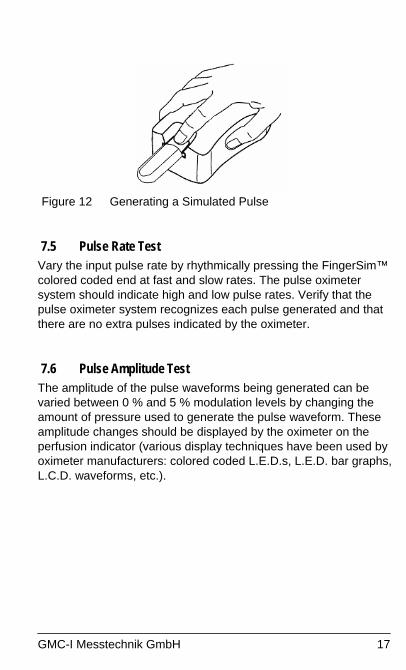
7.4 Oxygen Saturation Test Gently press the FingerSim’s™ color coded end rhythmically keeping a minimum pressure on the FingerSim™ throughout the pulse cycle (see Figure 12). Generate the pulse by slightly increasing and decreasing the pressure. Do not tap or move your finger away from the FingerSim™. This may create unwanted motion artifact by rocking the FingerSim™. The oximeter system should recognize the simulated pulse and display a pulse rate correlating to the input. The SpO2 display should approximate the nominal value of the FingerSim™. NOTE: Some slight variation in the SpO2 readings between
manufacturers is possible due to each manufacturer’s interpretation of how the SpO2 value relates to the absorption of the red and infrared light in blood (see Theory of Operation).
GMC-I Messtechnik GmbH 17
Figure 12 Generating a Simulated Pulse
7.5 Pulse Rate Test Vary the input pulse rate by rhythmically pressing the FingerSim™ colored coded end at fast and slow rates. The pulse oximeter system should indicate high and low pulse rates. Verify that the pulse oximeter system recognizes each pulse generated and that there are no extra pulses indicated by the oximeter.
7.6 Pulse Amplitude Test The amplitude of the pulse waveforms being generated can be varied between 0 % and 5 % modulation levels by changing the amount of pressure used to generate the pulse waveform. These amplitude changes should be displayed by the oximeter on the perfusion indicator (various display techniques have been used by oximeter manufacturers: colored coded L.E.D.s, L.E.D. bar graphs, L.C.D. waveforms, etc.).

18 GMC-I Messtechnik GmbH
8 SPECIFICATIONS
8.1 FingerSimTM
Width .72"
Thickness .50”
Overall Infrared Light Absorption (d.c.) 20 dB to 40 dB
Overall Red Light Absorption (d.c.) 20 dB to 40 dB
Operating Temperature Range 65 °F to 90° F
18.3 °C to 32.2 °C
Long Term Storage Temperature Range 32 °F to 104° F
0 °C to 40 °C
Typical infrared percent
modulation when squeezed 0 to 5 %
Red to Infrared Ratio (a.c.) @ 72.5 °F / 22.5 °C and
660 nm / 910 nm
80 % FingerSim™ - 1.065 to 1.100
90 % FingerSim™ - 0.765 to 0.800
97 % FingerSim™ - 0.573 to 0.598
8.2 Holder
Width 2.4”
Length 4.3”
Height 1.6”

GMC-I Messtechnik GmbH 19
9 SERVICE AND MAINTENANCE There is no service or maintenance possible with the FingerSim™ test systems. Each FingerSim™ is dated to identify its useful life. Replace any FingerSim™ that shows signs of leakage. To clean FingerSim™ wipe with isopropyl alcohol. 10 WARRANTY GMC-I Messtechnik GmbH warrants to the purchaser that each FingerSim™ shall be free of defects in materials and workmanship such that each system when properly used shall perform to specifications supplied within this manual until the calibration date marked on the FingerSim™ has elapsed. Note: This warranty specifically excludes any internal glass breakage. GMC-I Messtechnik shall replace all FingerSims™ or accessories found to be defective in accordance with this warranty, free of charge, for which GMC-I Messtechnik has been notified by the purchaser that there is a defect, provided said notification occurs within the applicable warranty period (i.e. before the calibration date). This warranty shall be the sole and exclusive remedy by the purchaser hereunder for any FingerSims™ or accessories delivered to the purchaser which are found to be defective in any manner whether such remedies be in contract, tort or by law. The FingerSim™ contains a substance prepared to very exact proportion and are assembled under precise specifications. They are not repairable and must be replaced at the first sign of deterioration or damage. Any sign of tampering or any kind of misuse or abuse shall void the warranty in its entirety. DISCLAIMER/EXCLUSIVITY OF WARRANTY. THE EXPRESS WARRANTIES SET FORTH IN THIS MANUAL (SECTION X) ARE EXCLUSIVE AND NO OTHER WARRANTIES OF ANY KIND, WHETHER STATUTORY, WRITTEN, ORAL, OR IMPLIED INCLUDING WARRANTIES OF FITNESS FOR A PARTICULAR PURPOSE OR MERCHANTABILITY SHALL APPLY.
20 GMC-I Messtechnik GmbH
11 ACCESSORIES The following accessories function with the FingerSim™ Oximeter Testing System: FingerSim™ Replacement Set Includes a set of three FingerSim™, 97 %, 90 % and 80 % SpO2 (Nominal). Replacement Holder FingerSim™ Holder

GMC-I Messtechnik GmbH 21
12 TROUBLE SHOOTING CHART Before calling Customer Support, please check the following chart for a possible solution to the problem you are experiencing. SYMPTOMS POSSIBLE CAUSE POSSIBLE SOLUTION
Oximeter measures slightly different SpO2 values than the 2 nominal FingerSim™ value.
Expected variation due to manufacturing tolerances.
Verify that minor variations in SpO2 are not clinically significant.
Oximeter measures high or low SpO2 bias compared to the nominal FingerSim™ value.
FingerSim™ is not at room temperature. Room temperature not at 72.5 °F / 22.5 °C. Cracked or leaking FingerSim™. Outside calibration date. Improper sensor attachment to the FingerSim™. Damaged Sensor Damaged Oximeter
Allow at least 1 hour stabilization at room temperature. Adjust expected SpO2 value (see Charts 6, 7, and 8). Replace FingerSim™. Replace FingerSim™. Ensure the sensor is attached to the FingerSim™ per section 8(8.1). Try another sensor. Try another oximeter.
Oximeter displays erratic SpO2 values
Motion of the sensor relative to the FingerSim™. Damaged Sensor Damaged Oximeter
Use holder provided. Route cable per 7(7.1). Be certain sensor is seated properly on FingerSim™. Try another sensor. Try another oximeter.
No pulse when the FingerSim™ is squeezed.
Cracked or leaking FingerSim™. Damaged Sensor Damaged Oximeter
Replace FingerSim™. Try another sensor. Try another oximeter.

22 GMC-I Messtechnik GmbH
Product Support If required please contact:
GMC-I Messtechnik GmbH Product Support Hotline Phone +49 911 8602-0 Fax +49 911 8602-709 E-Mail [email protected]
Service Center Repair and Replacement Parts Service Calibration Center * and Rental Instrument Service When you need service, please contact: GMC-I Service GmbH Service Center
Thomas-Mann-Strasse 20 90471 Nürnberg • Germany Phone +49 911 817718-0 Fax +49 911 817718-253 E-Mail [email protected] www.gmci-service.com
This address is only valid in Germany. Please contact our representatives or subsidiaries for service in other countries. * Calibration Laboratory for Electrical Quantities DKD – K – 19701 accredited per DIN EN ISO/IEC 17025:2005 Accredited measured quantities: direct voltage, direct current -values, DC -resistance, -alternating voltage, -alternating current -values, AC active power, AC apparent power, DC power, -capacitance, -frequency and temperature

GMC-I Messtechnik GmbH 23

Edited in Germany • Subject to change without notice • A pdf version is available on the Internet
GMC-I Messtechnik GmbH Südwestpark 15 90449 Nürnberg • Germany
Phone +49 911 8602-111 Fax +49 911 8602-777 E-mail [email protected] www.gossenmetrawatt.com