finite element analysis and design improvement of
TRANSCRIPT
FINITE ELEMENT ANALYSIS AND DESIGN IMPROVEMENT
OF AEROSPACE COMPOSITE HINGES
by
GAURANG GIRISH SONPAL
Presented to the Faculty of the Graduate School of
The University of Texas at Arlington in Partial Fulfillment
of the Requirements
for the Degree of
MASTER OF SCIENCE IN MECHANICAL ENGINEERING
THE UNIVERSITY OF TEXAS AT ARLINGTON
May 2018

ii
Copyright © by Gaurang Sonpal 2018
All Rights Reserved
iii
Acknowledgements
The completion of my research was achieved with the humble contribution from the MAE
faculty, my parents and my friends.
First and foremost, I would like to thank Dr. Andrey Beyle for guiding me throughout this
research work. Dr. Beyle’s extensive knowledge and expertise was immensely useful for
this research work.
I would like to thank Dr. Seiichi Nomura and Dr. Wen Shen for being part of my theses
defense committee and providing me with a unique perspective on this research.
I would like to thank my mother and father, Shilpa Sonpal and Girish Sonpal for their love
and support.
Lastly, I would like to thank my friends who supported me throughout this research.
May 4, 2018

iv
Abstract
FINITE ELEMENT ANALYSIS AND DESIGN IMPROVEMENT
OF AEROSPACE COMPOSITE HINGES
Gaurang Girish Sonpal, MS
The University of Texas at Arlington, 2018
Supervising Professor: Andrey Beyle
Hinges are the most commonly used mechanical bearings to connect 2 objects for relative
rotational motion. Modern day aerospace hinges are generally made using either
Aluminum, Steel or bronze. The study analyzes the use of composite material as an
alternative to traditional materials for manufacturing these hinges. The research is focused
on the Finite element Analysis of a composite hinge as well as an aluminum hinge. The
load capacity of both the types of hinges are compared. To improve the design of the
composite hinge, a combination of composite material and aluminum is used to model a
hybrid hinge design. The load capacity of this hybrid hinge is compared to that of an
aluminum hinge. The research also talks about the use of solid lubricants as an alternative
to traditional wet lubricants. This includes the different varieties of solid lubricants, their
properties and their usage in different operating conditions.
.
v
Table of Contents
Acknowledgements ............................................................................................................. iii
Abstract ............................................................................................................................... iv
List of Illustrations ............................................................................................................. viii
List of Tables ........................................................................................................................ x
Chapter 1 Hinges ................................................................................................................. 1
1.1 Hinge material ......................................................................................................... 1
1.2 Hinge nomenclature ................................................................................................ 2
1.3 Manufacturing methods for hinges .......................................................................... 3
1.4 Aerospace hinges .................................................................................................... 4
1.5 Continuous hinges ................................................................................................... 4
Chapter 2 Composite Hinges............................................................................................... 7
2.1 Composites............................................................................................................... 7
2.2 Composite hinge model........................................................................................... 9
2.3 Manufacturing methodology .................................................................................. 11
2.4 Aluminum hinge ..................................................................................................... 11
Chapter 3 Finite Element Analysis .................................................................................... 12
3.1 Meshing ................................................................................................................. 12
3.2 Loads and faulire criteria ....................................................................................... 13
3.3 Connections/ Constraints ...................................................................................... 15
3.4 Vertical load analysis............................................................................................. 16
3.5 Horizontal radial bearing load capacity ................................................................. 20
3.6 Vertical radial bearing load capacity ..................................................................... 25
3.7 FEA Summary ....................................................................................................... 28
3.8 Analytical calculations ........................................................................................... 29
vi
Chapter 4 Hybrid hinge ...................................................................................................... 33
Chapter 5 Solid lubrication Literature review ..................................................................... 36
5.1 Graphite ................................................................................................................. 37
5.2 PTFE ..................................................................................................................... 38
5.3 Polyimides ............................................................................................................. 39
5.4 UHMWPE .............................................................................................................. 39
5.5 MoS2 ...................................................................................................................... 40
5.6 Self-lubricating composites ................................................................................... 41
5.7 Mechanism for lubrication ..................................................................................... 42
5.8 Application methods for Solid lubricants ................................................................ 43
5.8 Uses of Hybrid Composite hinge ............................................................................ 44
Chapter 6 Conclusion ........................................................................................................ 45
Chapter 7 Future Work ...................................................................................................... 45
Appendix A Material properties.......................................................................................... 47
Appendix B Load capacity comparisons ............................................................................ 50
References ......................................................................................................................... 53
Biographical Information .................................................................................................... 54

vii
List of Illustrations
Figure 1. Hinge nomenclature ............................................................................................. 2
Figure 2. Guide used to model MS20001 hinge .................................................................. 5
Figure 3. Isometric view of the model ................................................................................. 6
Figure 4. Side view .............................................................................................................. 6
Figure 5. Top view...............................................................................................................6
Figure 6. Fiber reinforced composites.................................................................................7
Figure 7. Stack up sequence and Polar properties of the 20 plies stack up........................8
Figure 8. Composite hinge CAD model..............................................................................9
Figure 9. Gap in the Composite CAD model......................................................................9
Figure 10. Mold shape with layup and stacking directions...............................................10
Figure 11. Sealing of edges...............................................................................................11
Figure 12. Sol185 element.................................................................................................12
Figure 13. Meshed model..................................................................................................13
Figure 14. Loads acting on vertically installed hinge........................................................14
Figure 15. MPC face connections......................................................................................15
Figure 16. MPC connections to simulate rigid pin............................................................16
Figure 17. Vertical load illustration...................................................................................16
Figure 18. Safety factor comparison. for vertical load of 600 lb.......................................17
Figure 19. Stresses in matrix due to vertical load of 900 lb..............................................17
Figure 20. Increase in matrix stress at critical element......................................................18
Figure 21. Failure distribution due to 900 lbf vertical load ............................................... 18
Figure 22. Max shear stress distribution (Aluminum- Vertical load) ................................ 19
viii
Figure 23. Horizontal radial bearing load depiction .......................................................... 20
Figure 24. 3D model of lug joint ....................................................................................... 20
Figure 25. Meshed model of lug joint ............................................................................... 20
Figure 26. MPC connections for rigid pin (Lug joint)....................................................... 21
Figure 27. Stresses distribution in fibers (Horizontal bearing load) .................................. 22
Figure 28. Fiber stresses at critical element (Horizontal bearing load) ............................. 22
Figure 29. Failure distribution (Horizontal bearing load) ................................................. 22
Figure 30. Max shear stress distribution (Aluminum- Horizontal bearing load) (i) .......... 23
Figure 31. Max shear stress distribution (Aluminum- Horizontal bearing load) (ii) ........ 23
Figure 32. Shear failure depiction (Horizontal bearing load) ............................................ 24
Figure 33. Vertical radial load illustration ......................................................................... 25
Figure 34. Stresses in fiber (Vertical bearing load) ........................................................... 26
Figure 35. Fiber stresses at critical element (Vertical bearing load) ................................. 26
Figure 36. Failure distribution (Vertical bearing load) ...................................................... 26
Figure 37. Max shear stress distribution (Vertical bearing load) ...................................... 27
Figure 38. Shear failure depiction (Vertical bearing load) ................................................ 27
Figure 39. Lug failure modes............................................................................................. 29
Figure 40 Shear stresses on the outer surface of the lug.................................................... 31
Figure 41 Hybrid hinge design .......................................................................................... 33
Figure 42. Stack up and polar properties of hybrid hinge composite core ........................ 33
Figure 43. Vertical load capacity comparison of Hybrid hinge ........................................ 34
Figure 44. Overall mass comparison for different hinge materials ................................... 35
Figure 45. Plane view of graphite layer stacking .............................................................. 37
ix
Figure 46. PTFE chain ....................................................................................................... 38
Figure 47. Chemical structure of polyimide ...................................................................... 39
Figure 48. Chemical structure of UHMPE ........................................................................ 39
Figure 49. MoS2 crystal structure ...................................................................................... 40
Figure 50. Components of solid lubricating composites ................................................... 41
Figure 51. Solid lubrication application on the hinge........................................................ 43
Figure 52. Horizontal radial bearing load capacity [LUG]................................................ 51
Figure 53. Horizontal radial bearing load capacity [HINGE] ........................................... 51
Figure 54. Vertical radial load bearing capacity [HINGE]................................................ 52
x
List of Tables
Table 1 Finite Element Analysis results ............................................................................ 28
Table 2 Solid lubrication and wet lubrication comparison ................................................ 36
Table 3 Aluminum alloy properties ................................................................................... 48
Table 4 Carbon Epoxy composite properties..................................................................... 49
1
Chapter 1
Hinges
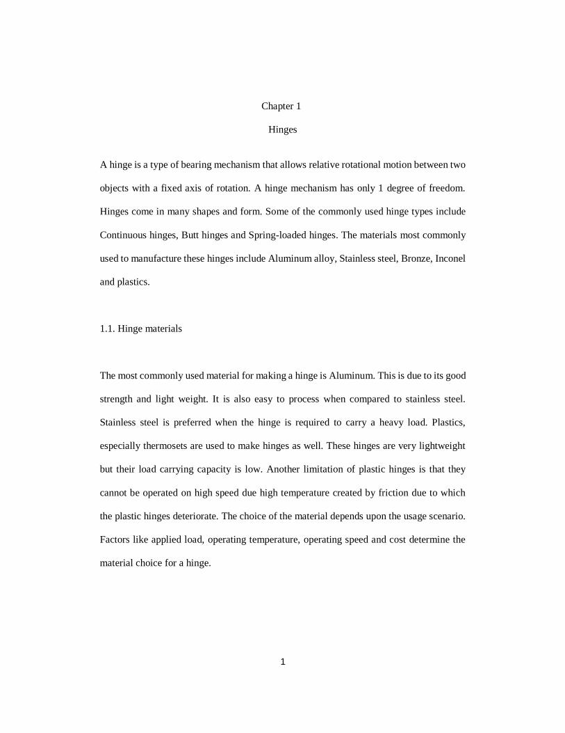
A hinge is a type of bearing mechanism that allows relative rotational motion between two
objects with a fixed axis of rotation. A hinge mechanism has only 1 degree of freedom.
Hinges come in many shapes and form. Some of the commonly used hinge types include
Continuous hinges, Butt hinges and Spring-loaded hinges. The materials most commonly
used to manufacture these hinges include Aluminum alloy, Stainless steel, Bronze, Inconel
and plastics.
1.1. Hinge materials
The most commonly used material for making a hinge is Aluminum. This is due to its good
strength and light weight. It is also easy to process when compared to stainless steel.
Stainless steel is preferred when the hinge is required to carry a heavy load. Plastics,
especially thermosets are used to make hinges as well. These hinges are very lightweight
but their load carrying capacity is low. Another limitation of plastic hinges is that they
cannot be operated on high speed due high temperature created by friction due to which
the plastic hinges deteriorate. The choice of the material depends upon the usage scenario.
Factors like applied load, operating temperature, operating speed and cost determine the
material choice for a hinge.
2
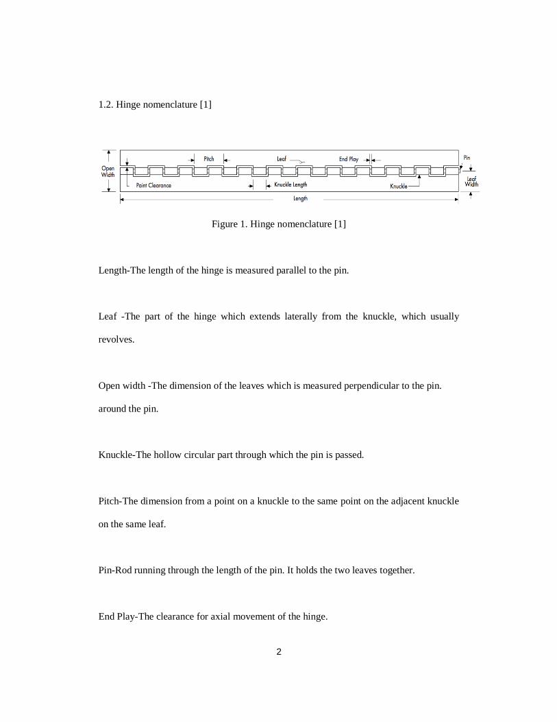
1.2. Hinge nomenclature [1]
Figure 1. Hinge nomenclature [1]
Length-The length of the hinge is measured parallel to the pin.
Leaf -The part of the hinge which extends laterally from the knuckle, which usually
revolves.
Open width -The dimension of the leaves which is measured perpendicular to the pin.
around the pin.
Knuckle-The hollow circular part through which the pin is passed.
Pitch-The dimension from a point on a knuckle to the same point on the adjacent knuckle
on the same leaf.
Pin-Rod running through the length of the pin. It holds the two leaves together.
End Play-The clearance for axial movement of the hinge.

3
1.3. Manufacturing methods for hinges [2]
Hinges are manufactured using different techniques that include Extrusion, Casting and
cold working.
Extrusion
In this method the metal component is compressed against a die. This method gives us very
strong hinges, but the manufacturing cost is much higher.
Casting
In this process the metal used has to be melted first. After this the liquid metal is poured
into a mold which is of the shape of a hinge leaf. The metal then solidifies after which the
part is removed from the mold. The strength of these hinges is less than that of the hinges
produced by extrusion.
Cold working
In this technique the metal is subjected to external force which produces mechanical
stresses which in turn changes the crystalline structure of the metal. This makes the hinges
stronger.
Thus, in conclusion the strength of a hinge is highly dependent on its manufacturing
process.
4
1.4. Aerospace hinges
Aerospace hinges are specialty hinge designed specifically for commercial and military
aerospace applications. These hinges have to endure harsh environmental conditions in
which ordinary hinges cannot function optimally. Some of these environmental factors
include zero gravity, very high and low temperatures and radiation. The dimensional
tolerance for aerospace hinges is very high. Aerospace hinges are designed according to
strict military standards for compatibility and easy replacement. These hinges can be found
on the exterior as well the interior of an aircraft. These include cargo doors, wings and tail
assemblies. These hinges are also used in space satellites and other devices that are
deployed in the outer space. [2]
1.5. Continuous Aerospace hinges
Continuous hinges are the most widely used type of hinges. This is due their ease of
manufacturing and their ability to support loads over a long length. These hinges evenly
distribute the load over an entire length thus providing stability and reducing the stresses
developed. Mounting methods for continuous hinges include welding, screwing or bolting
and using adhesives. The natural factor of safety for these continuous hinges is taken as
1.5, and for this factor of safety we consider yield load as criteria and not the ultimate
tensile load. For this research we will be focusing on the Military standard continuous
hinges. The hinges specifically taken into consideration is the MS20001 hinge.

5
Figure 2. The guide used to model a MS20001 hinge. [4]

6
Following this design criteria, a CAD model was created in Solidworks.
Figure 3. Isometric view of the model
Figure 4. Side view
Figure 5. Top view
7
CHAPTER 2
Composite Hinge
2.1. Composites
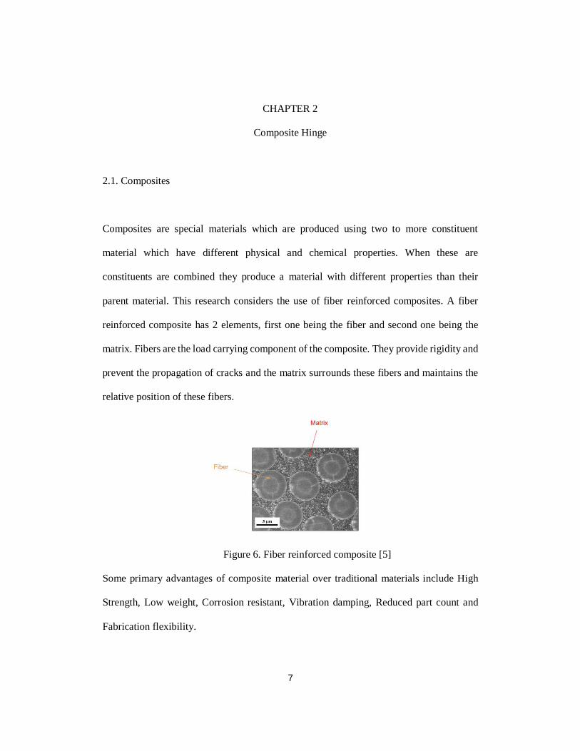
Composites are special materials which are produced using two to more constituent
material which have different physical and chemical properties. When these are
constituents are combined they produce a material with different properties than their
parent material. This research considers the use of fiber reinforced composites. A fiber
reinforced composite has 2 elements, first one being the fiber and second one being the
matrix. Fibers are the load carrying component of the composite. They provide rigidity and
prevent the propagation of cracks and the matrix surrounds these fibers and maintains the
relative position of these fibers.
Figure 6. Fiber reinforced composite [5]
Some primary advantages of composite material over traditional materials include High
Strength, Low weight, Corrosion resistant, Vibration damping, Reduced part count and
Fabrication flexibility.
8
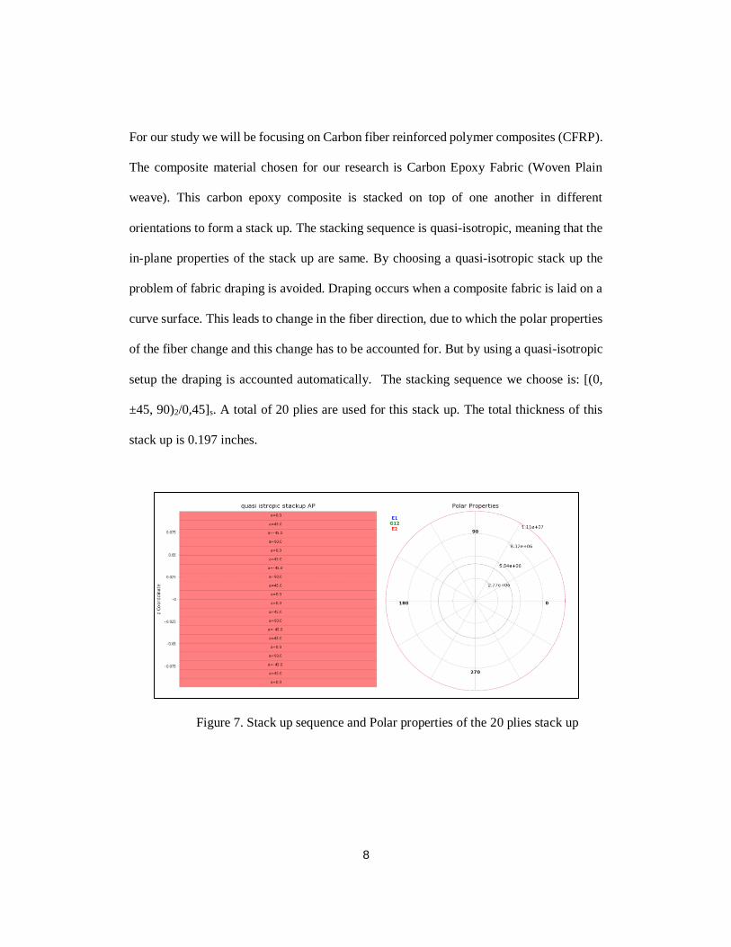
For our study we will be focusing on Carbon fiber reinforced polymer composites (CFRP).
The composite material chosen for our research is Carbon Epoxy Fabric (Woven Plain
weave). This carbon epoxy composite is stacked on top of one another in different
orientations to form a stack up. The stacking sequence is quasi-isotropic, meaning that the
in-plane properties of the stack up are same. By choosing a quasi-isotropic stack up the
problem of fabric draping is avoided. Draping occurs when a composite fabric is laid on a
curve surface. This leads to change in the fiber direction, due to which the polar properties
of the fiber change and this change has to be accounted for. But by using a quasi-isotropic
setup the draping is accounted automatically. The stacking sequence we choose is: [(0,
±45, 90)2/0,45]s. A total of 20 plies are used for this stack up. The total thickness of this
stack up is 0.197 inches.
Figure 7. Stack up sequence and Polar properties of the 20 plies stack up
9
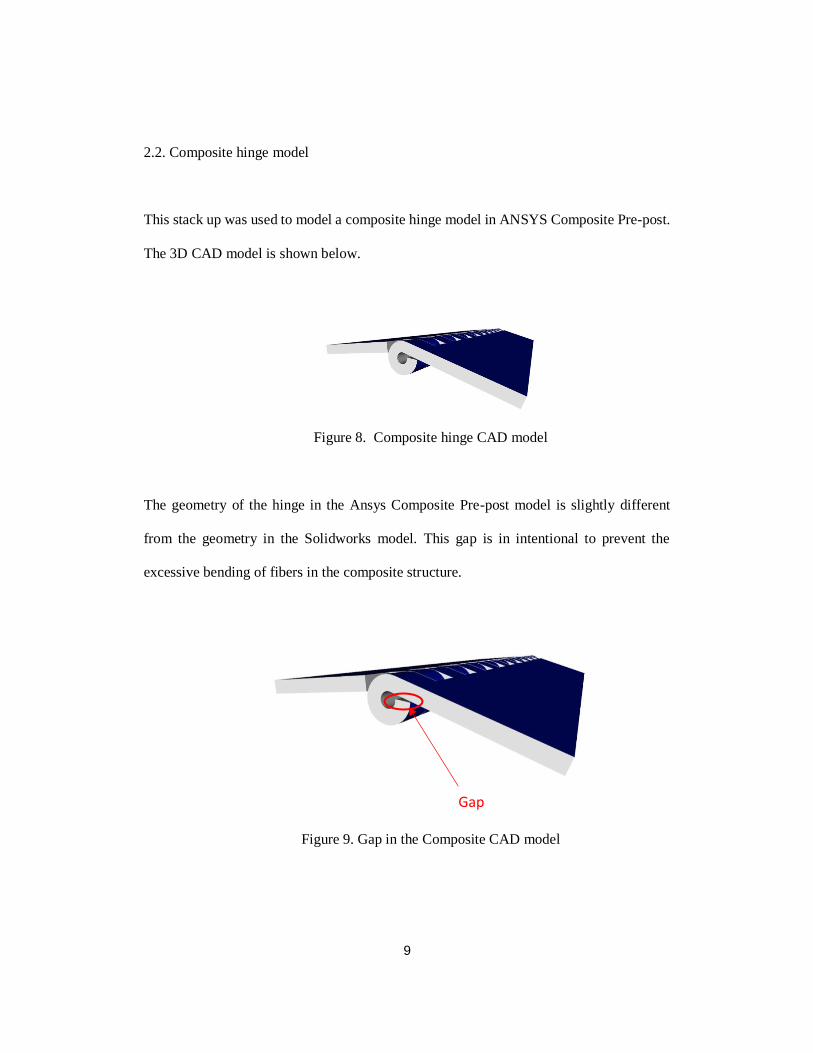
2.2. Composite hinge model
This stack up was used to model a composite hinge model in ANSYS Composite Pre-post.
The 3D CAD model is shown below.
Figure 8. Composite hinge CAD model
The geometry of the hinge in the Ansys Composite Pre-post model is slightly different
from the geometry in the Solidworks model. This gap is in intentional to prevent the
excessive bending of fibers in the composite structure.
Figure 9. Gap in the Composite CAD model
Gap
10
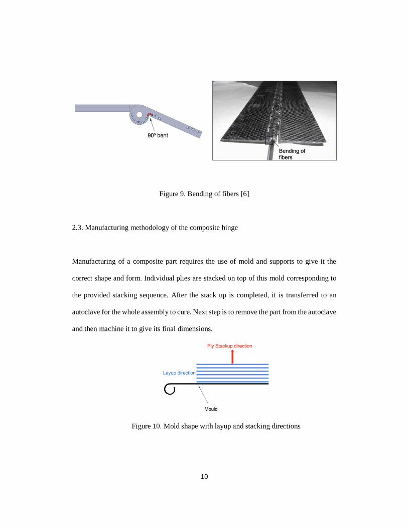
Figure 9. Bending of fibers [6]
2.3. Manufacturing methodology of the composite hinge
Manufacturing of a composite part requires the use of mold and supports to give it the
correct shape and form. Individual plies are stacked on top of this mold corresponding to
the provided stacking sequence. After the stack up is completed, it is transferred to an
autoclave for the whole assembly to cure. Next step is to remove the part from the autoclave
and then machine it to give its final dimensions.
Figure 10. Mold shape with layup and stacking directions
11
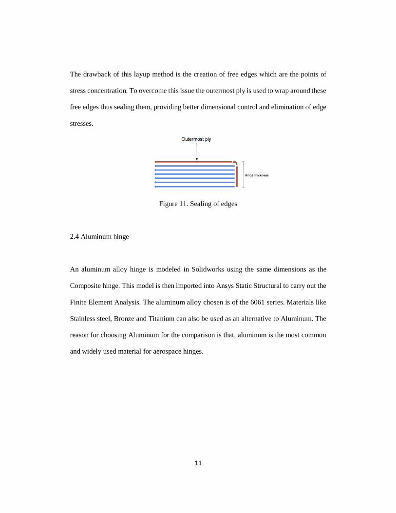
The drawback of this layup method is the creation of free edges which are the points of
stress concentration. To overcome this issue the outermost ply is used to wrap around these
free edges thus sealing them, providing better dimensional control and elimination of edge
stresses.
Figure 11. Sealing of edges
2.4 Aluminum hinge
An aluminum alloy hinge is modeled in Solidworks using the same dimensions as the
Composite hinge. This model is then imported into Ansys Static Structural to carry out the
Finite Element Analysis. The aluminum alloy chosen is of the 6061 series. Materials like
Stainless steel, Bronze and Titanium can also be used as an alternative to Aluminum. The
reason for choosing Aluminum for the comparison is that, aluminum is the most common
and widely used material for aerospace hinges.

12
CHAPTER 3
Finite Element Analysis
Both the models, the composite hinge 3D model and the aluminum hinge model are
completed. After this these models are loaded into Ansys static structural to carry out the
Finite element analysis.
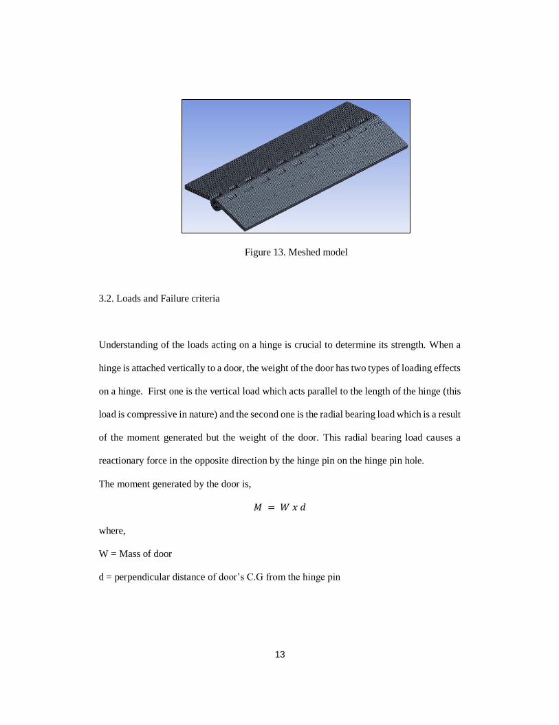
3.1. Meshing
The CAD model generated is meshed using solid elements (brick elements). The
designation of these elements is SOL185. This element type has 8 nodes. Each of these
nodes has 3 degrees of freedom which is translation in X, Y and Z directions. Other features
of this element include Plasticity, Stress stiffening, Large deflection and Large strain. This
element type has orthotropic properties. The final meshed model has 13282 elements in
total.
Figure 12. Sol185 element [7]
13
Figure 13. Meshed model
3.2. Loads and Failure criteria
Understanding of the loads acting on a hinge is crucial to determine its strength. When a
hinge is attached vertically to a door, the weight of the door has two types of loading effects
on a hinge. First one is the vertical load which acts parallel to the length of the hinge (this
load is compressive in nature) and the second one is the radial bearing load which is a result
of the moment generated but the weight of the door. This radial bearing load causes a
reactionary force in the opposite direction by the hinge pin on the hinge pin hole.
The moment generated by the door is,
𝑀 = 𝑊 𝑥 𝑑
where,
W = Mass of door
d = perpendicular distance of door’s C.G from the hinge pin
14
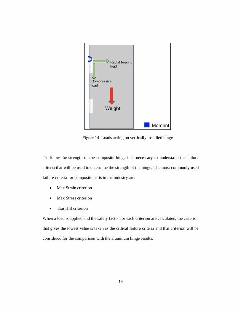
Figure 14. Loads acting on vertically installed hinge
To know the strength of the composite hinge it is necessary to understand the failure
criteria that will be used to determine the strength of the hinge. The most commonly used
failure criteria for composite parts in the industry are:
• Max Strain criterion
• Max Stress criterion
• Tsai Hill criterion
When a load is applied and the safety factor for each criterion are calculated, the criterion
that gives the lowest value is taken as the critical failure criteria and that criterion will be
considered for the comparison with the aluminum hinge results.
15
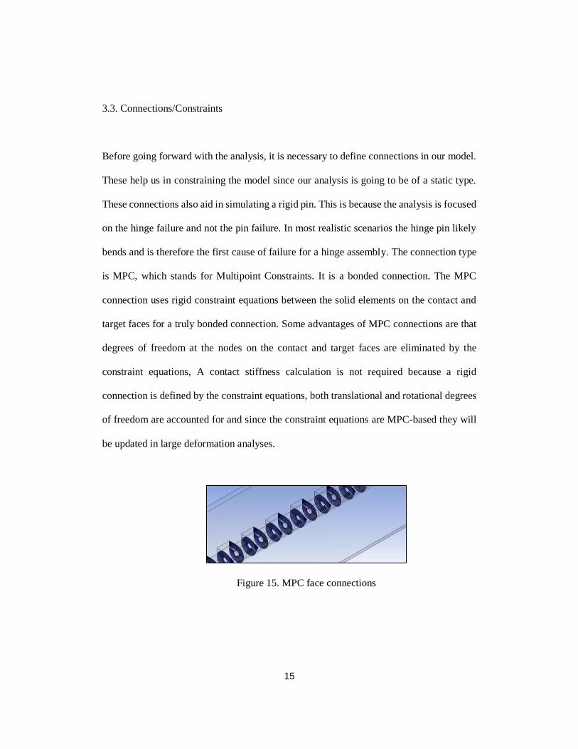
3.3. Connections/Constraints
Before going forward with the analysis, it is necessary to define connections in our model.
These help us in constraining the model since our analysis is going to be of a static type.
These connections also aid in simulating a rigid pin. This is because the analysis is focused
on the hinge failure and not the pin failure. In most realistic scenarios the hinge pin likely
bends and is therefore the first cause of failure for a hinge assembly. The connection type
is MPC, which stands for Multipoint Constraints. It is a bonded connection. The MPC
connection uses rigid constraint equations between the solid elements on the contact and
target faces for a truly bonded connection. Some advantages of MPC connections are that
degrees of freedom at the nodes on the contact and target faces are eliminated by the
constraint equations, A contact stiffness calculation is not required because a rigid
connection is defined by the constraint equations, both translational and rotational degrees
of freedom are accounted for and since the constraint equations are MPC-based they will
be updated in large deformation analyses.
Figure 15. MPC face connections

16
Figure 16. MPC connections to simulate rigid pin
3.4 Vertical load analysis
The compressive vertical acts on the leaf of hinge which is attached to the door. This leaf
is free to rotate along the hinge axis. The other leaf is considered as a fixed support.
Figure 17. Vertical load illustration
The load on the hinge is slowly increased, it is observed that a force of 600 lb. gives the
lowest safety factor. We will consider the Tsai Hill criteria since it’s the most critical out
of the 3.

17
Figure 18. Safety factor comparison. for vertical load of 600 lb.
As the force on the hinges is increased the Tsai hill (3D) criterion becomes the critical
criterion because it is the fastest to reach below the value of 1. The failure load is 900 lb.
and the mode of failure is that of the matrix compression.
Figure 19. Stresses in matrix due to vertical load of 900 lb.
18
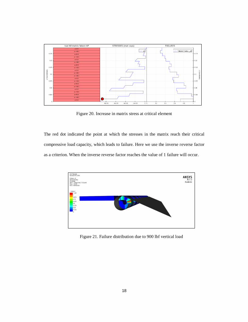
Figure 20. Increase in matrix stress at critical element
The red dot indicated the point at which the stresses in the matrix reach their critical
compressive load capacity, which leads to failure. Here we use the inverse reverse factor
as a criterion. When the inverse reverse factor reaches the value of 1 failure will occur.
Figure 21. Failure distribution due to 900 lbf vertical load

19
The aluminum hinge model is subjected to gradually increasing load. It is seen that for a
load of 1200 lb. the Maximum shear stress factor of safety reaches a value of 1.5. The
Maximum Von Misses Factor of Safety is 1.78 for the same load. Therefore, we will take
the Maximum shear stress safety criterion as the most critical one. This also indicates that
the mode of failure for the aluminum hinge is Shear failure. A load of 1800 lb. causes the
shear failure to occur on the aluminum hinge.
Figure 22. Max shear stress distribution (Aluminum- Vertical load)
Comparing the vertical load capacity of both the hinges, it is observed that the vertical
compressive load capacity for the composite hinge is 50% of that of an aluminum hinge.
Failure region
20
3.5. Horizontal Radial bearing load capacity
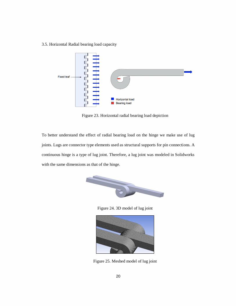
Figure 23. Horizontal radial bearing load depiction
To better understand the effect of radial bearing load on the hinge we make use of lug
joints. Lugs are connector type elements used as structural supports for pin connections. A
continuous hinge is a type of lug joint. Therefore, a lug joint was modeled in Solidworks
with the same dimensions as that of the hinge.
Figure 24. 3D model of lug joint
Figure 25. Meshed model of lug joint
21
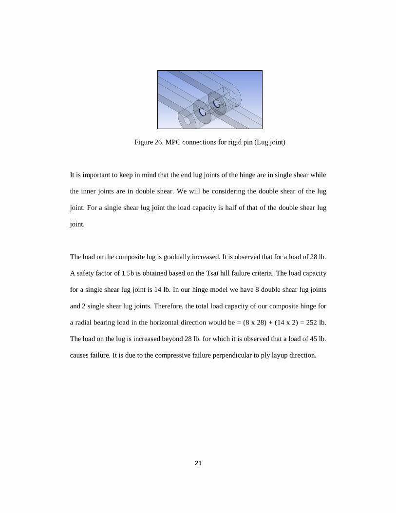
Figure 26. MPC connections for rigid pin (Lug joint)
It is important to keep in mind that the end lug joints of the hinge are in single shear while
the inner joints are in double shear. We will be considering the double shear of the lug
joint. For a single shear lug joint the load capacity is half of that of the double shear lug
joint.
The load on the composite lug is gradually increased. It is observed that for a load of 28 lb.
A safety factor of 1.5b is obtained based on the Tsai hill failure criteria. The load capacity
for a single shear lug joint is 14 lb. In our hinge model we have 8 double shear lug joints
and 2 single shear lug joints. Therefore, the total load capacity of our composite hinge for
a radial bearing load in the horizontal direction would be = (8 x 28) + (14 x 2) = 252 lb.
The load on the lug is increased beyond 28 lb. for which it is observed that a load of 45 lb.
causes failure. It is due to the compressive failure perpendicular to ply layup direction.

22
Fig 27. Stresses distribution in fibers (Horizontal bearing load)
Figure 28. Fiber stresses at critical element (Horizontal bearing load)
Figure 29. Failure distribution (Horizontal bearing load)
23
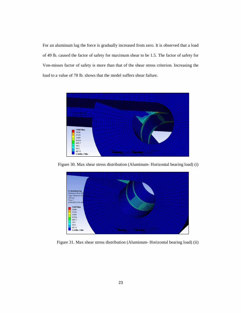
For an aluminum lug the force is gradually increased from zero. It is observed that a load
of 49 lb. caused the factor of safety for maximum shear to be 1.5. The factor of safety for
Von-misses factor of safety is more than that of the shear stress criterion. Increasing the
load to a value of 78 lb. shows that the model suffers shear failure.
Figure 30. Max shear stress distribution (Aluminum- Horizontal bearing load) (i)
Figure 31. Max shear stress distribution (Aluminum- Horizontal bearing load) (ii)
24
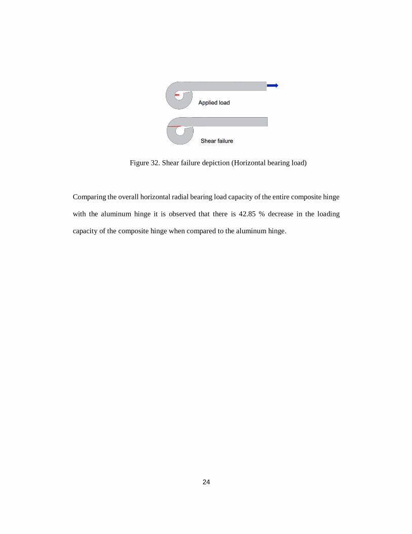
Figure 32. Shear failure depiction (Horizontal bearing load)
Comparing the overall horizontal radial bearing load capacity of the entire composite hinge
with the aluminum hinge it is observed that there is 42.85 % decrease in the loading
capacity of the composite hinge when compared to the aluminum hinge.
25
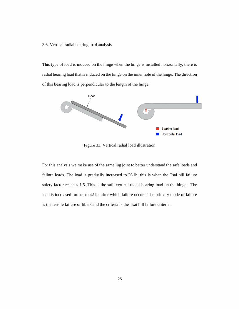
3.6. Vertical radial bearing load analysis
This type of load is induced on the hinge when the hinge is installed horizontally, there is
radial bearing load that is induced on the hinge on the inner hole of the hinge. The direction
of this bearing load is perpendicular to the length of the hinge.
Figure 33. Vertical radial load illustration
For this analysis we make use of the same lug joint to better understand the safe loads and
failure loads. The load is gradually increased to 26 lb. this is when the Tsai hill failure
safety factor reaches 1.5. This is the safe vertical radial bearing load on the hinge. The
load is increased further to 42 lb. after which failure occurs. The primary mode of failure
is the tensile failure of fibers and the criteria is the Tsai hill failure criteria.

26
Figure 34. Stresses in fiber (Vertical bearing load)
Figure 35. Fiber stresses at critical element (Vertical bearing load)
Figure 36. Failure distribution (Vertical bearing load)
27
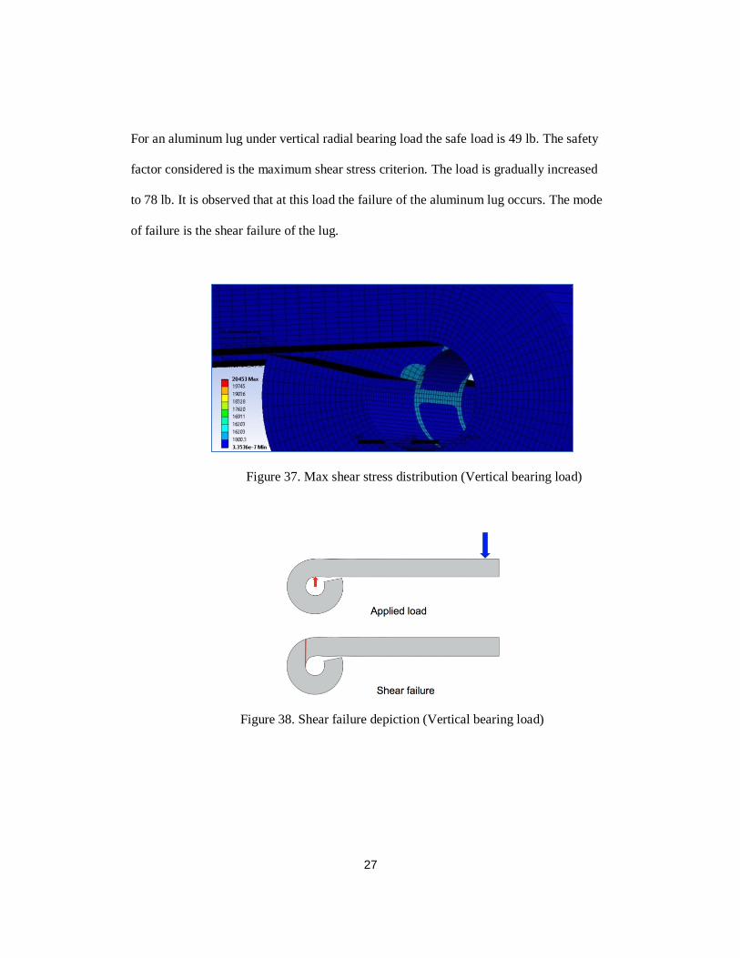
For an aluminum lug under vertical radial bearing load the safe load is 49 lb. The safety
factor considered is the maximum shear stress criterion. The load is gradually increased
to 78 lb. It is observed that at this load the failure of the aluminum lug occurs. The mode
of failure is the shear failure of the lug.
Figure 37. Max shear stress distribution (Vertical bearing load)
Figure 38. Shear failure depiction (Vertical bearing load)
28
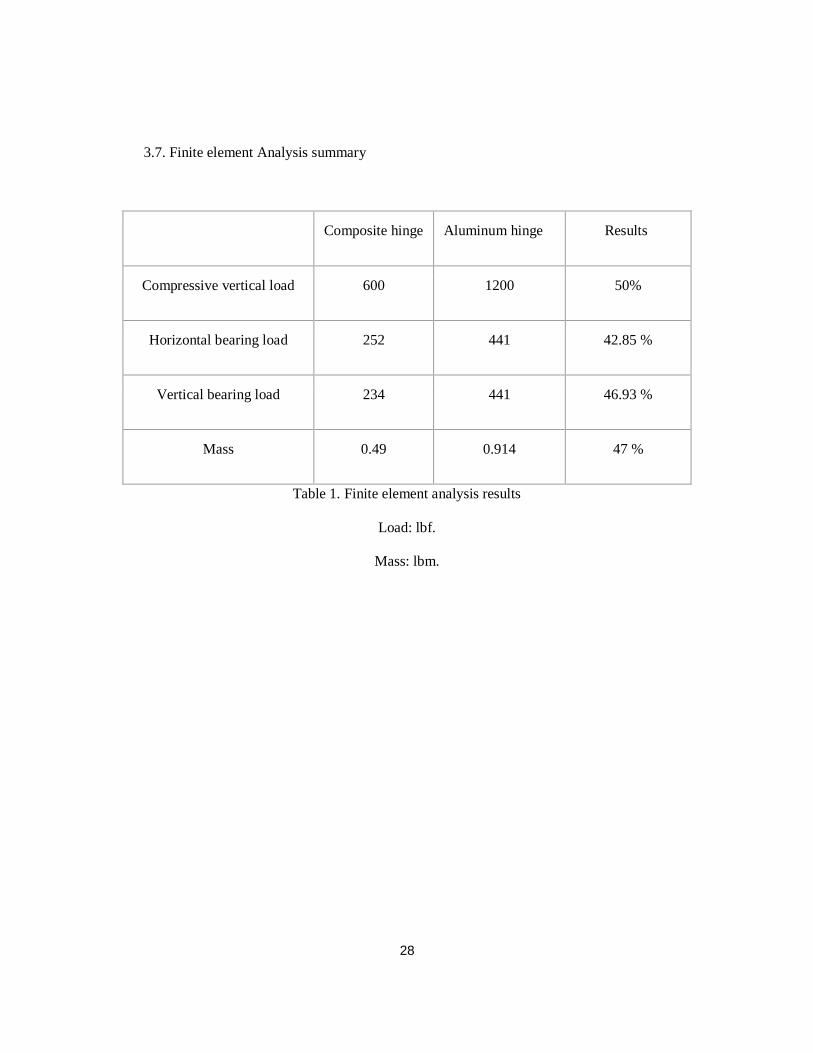
3.7. Finite element Analysis summary
Composite hinge Aluminum hinge Results
Compressive vertical load 600 1200 50%
Horizontal bearing load 252 441 42.85 %
Vertical bearing load 234 441 46.93 %
Mass 0.49 0.914 47 %
Table 1. Finite element analysis results
Load: lbf.
Mass: lbm.
29
3.8. Analytical calculations:
The accuracy of the Finite Element Analysis can be estimated by comparing the results
with analytical calculations. Since there are no analytical formulae for a composite lug
failure, we will focus on the analytical formulae for the failure of the aluminum lug.
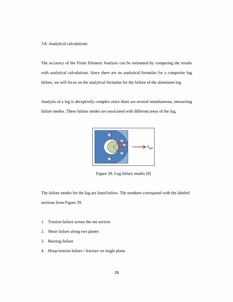
Analysis of a lug is deceptively complex since there are several simultaneous, interacting
failure modes. These failure modes are associated with different areas of the lug.
Figure 39. Lug failure modes [8]
The failure modes for the lug are listed below. The numbers correspond with the labeled
sections from Figure 39.
1. Tension failure across the net section
2. Shear failure along two planes
3. Bearing failure
4. Hoop tension failure / fracture on single plane
30
The failure of a lug joint can be predicted using 3 methods.
• Simplified Analysis
This method is based on first principles and involves making simplifying assumptions
about the nature of the failure and calculating factors of safety. [8]
• Air force method
This method follows closely with the methods presented in Melcon & Hoblit and Bruhn.
It relies heavily on curves generated by empirical data. This method takes into account
the interaction between the lug and the pin. Since our pin is rigid we do not adopt this
method for analytical failure analysis. [8]
• ASME BTH
The ASME method of lug analysis is described in ASME BTH-1, "Design of Below-the-
Hook Lifting Devices". This method also takes into account the interaction between the
lug and the pin. Since our pin is rigid we do not adopt this method for analytical failure
analysis. [8]
31
Therefore, we will be adopting the Simplified Analysis approach for calculating the failure
of the aluminum lug. The mode of failure considered will be the shear tear out, for the
aluminum lug.
𝐴𝑠 = 𝑡𝑜𝑡𝑎𝑙 𝑠ℎ𝑒𝑎𝑟 𝑝𝑙𝑎𝑛𝑒 𝑎𝑟𝑒𝑎 = 0.21 𝑖𝑛2
𝑆𝑠𝑦 = 𝑌𝑖𝑒𝑙𝑑 𝑠ℎ𝑒𝑎𝑟 𝑠𝑡𝑟𝑒𝑛𝑔𝑡ℎ
𝑆𝑠𝑦 = 0.55 ✕ 𝑡𝑒𝑛𝑠𝑖𝑙𝑒 𝑦𝑖𝑒𝑙𝑑 𝑠𝑡𝑟𝑒𝑛𝑔𝑡ℎ = 20305 𝑝𝑠𝑖
𝑃𝑠𝑦 = 𝑦𝑖𝑒𝑙𝑑 𝑠ℎ𝑒𝑎𝑟 𝑙𝑜𝑎𝑑 = 𝑆𝑠𝑦 ✕ 𝐴𝑠 = 𝟒𝟐𝟔𝟒. 𝟎𝟓 𝒍𝒃𝒇
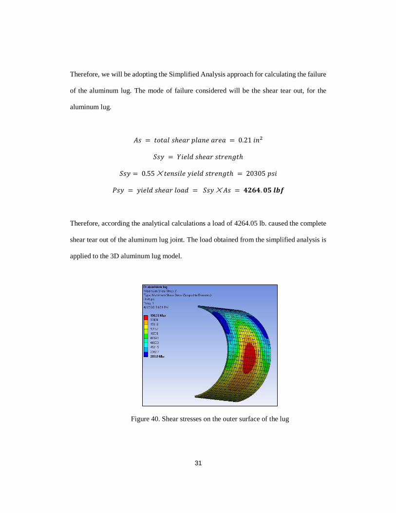
Therefore, according the analytical calculations a load of 4264.05 lb. caused the complete
shear tear out of the aluminum lug joint. The load obtained from the simplified analysis is
applied to the 3D aluminum lug model.
Figure 40. Shear stresses on the outer surface of the lug
32
The area chosen to compare is the outer surface of the lug. If the stresses on this surface go
beyond the maximum shear stress capacity of aluminum, failure occurs. Observing the
FEA results the maximum stress developed on the outer surface is 19633 psi. While for the
analytical approach the shear stress calculated is 20305 psi. Comparing both the stress
values we conclude that there is a 3.3 % variation in solutions for the analytical and FEA
analysis.
33
CHAPTER 4
Hybrid hinge
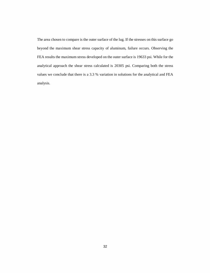
To improve the strength of the composite hinge, a new kind of. hinge design was
proposed. In this hinge design. A composite stack up is sandwiched between two
aluminum sheets. The composite stack up has 10 plies in total.
Figure 41. Hybrid hinge design
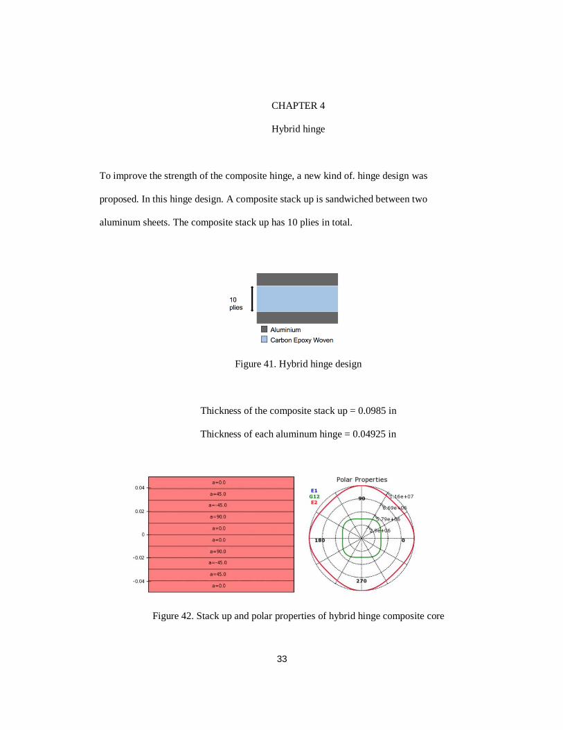
Thickness of the composite stack up = 0.0985 in
Thickness of each aluminum hinge = 0.04925 in
Figure 42. Stack up and polar properties of hybrid hinge composite core

34
When a vertical compressive load is applied on the hinge it is observed that for a load of
1100 lb. the safety factor is 1.5. When the load is increased to 1550 lb. failure is observed.
Figure 43. Vertical load capacity comparison of Hybrid hinge
We conclude that from a 50 % reduction of vertical compressive loading capacity of the
composite hinge, the hybrid hinge has a loading capacity which is just 8.3 % lower than
that of an aluminum hinge. There is no change in the bearing load capacity for the hybrid
hinge when compared to the aluminum hinge.
Comparing of the mass of hinges made using different materials it is seen that the
composite hinge is the lightest while a hinge made using steel is heaviest. The aluminum
hinge is lighter than the steel hinge but heavier than the composite hinge. The hybrid hinge
is lighter than aluminum but slightly heavier than the composite hinge. The hybrid hinge
is 23.41 % lighter than aluminum.

35
Figure 44. Overall mass comparison for different hinge materials

36
CHAPTER 5
Solid lubricants literature review
Dry lubricants or solid lubricants are materials that, despite being in the solid phase, are
able to reduce friction between two surfaces sliding against each other without the need for
a liquid oil medium. [10]
Solid lubricants Wet lubricants
Negligible vapor pressure (no contamination) Finite vapor pressure
Friction speed independent Friction speed dependent
Low temperature sensitivity Sensitive to temperature
No viscosity effects Affected by viscosity
Electrically conductive Electrically insulative
Table 2. Solid lubrication and wet lubrication comparison [10]

37
There are numerous types of solid lubricants available, some of them are:
Soft metal - Au, Ag, Pb.
Lamellar solids- MoS2, WS2.
Polymers - PTFE, Polyimide, UHWPE, Epoxy resins, Polyester.
Soft solids - Cd, Zn, Co.
For this study we will focusing on Lamellar solid and Polymer based solid lubricants.
5.1. Graphite
Figure 45. Plane view of graphite layer stacking
Graphite is lamellar solid which is extensively used as a solid lubricant. The crystal
lattice of graphite consists of hexagonal rings forming thin parallel planes (graphene). Each
carbon atom is covalently bonded to three other atoms in the plate (the angle between two
bonds is 120°). The graphene are bonded to each other by weak Van der Waals forces. The
layered structure allows sliding movement of the parallel planes. Weak bonding between
the planes provides low shear strength in the direction of the sliding movement but high
compression strength in the direction perpendicular to the sliding movement.
Friction forces cause the graphite particles to orient in the direction, in which the graphene

38
are parallel to the sliding movement. The anisotropy of the mechanical properties imparts
the combination of low coefficient of friction and high carrying load capacity to graphite.
Lubricating properties of graphite are highly dependent on the presence of vapor in the
ambient atmosphere. [10]
5.2. PTFE
Figure 46. PTFE chain
PTFE is widely used as a solid lubricant. PTFE does not have a layered structure. The
macro molecules of PTFE slip easily along each other, similar to lamellar structures. PTFE
shows one of the smallest coefficients of static and dynamic friction, down to 0.04.
Operating temperatures are limited from -73 ºC to 290ºC. PTFE is also hydrophobic.
Sometimes additional additives are required to improve the load bearing capacity of PTFE
lubricants. [10]

39
5.3. Polyimides
Figure 47. Chemical structure of polyimide
Polyimides have better load carrying capacity than PTFE with low friction. Additives are
not required in case of Polyimides since their inherent load carrying capacity is higher than
PTFE. These polymers are suited to operate in the temperature range of 25℃ to 300℃. It
is important to keep in mind that these polymers are sensitive to the presence of water vapor
hence cannot be effectively used in atmospheric conditions. Polyimides also have among
the lowest wear rate. Also, polyimide composite can be used as bearing material for several
applications. [10]
5.4. UHMWPE (Ultra high Molecular Weight Polyethylene)
Figure 48. Chemical structure of UHMPE
40
UHMWPE have excellent load carrying capacity (Highest impact strength of any
thermoplastic). These also excel at lower temperatures. The downside to UHMWPE is that
it melts at 101 ℃, therefore it cannot be used in high temperature environments. [10]
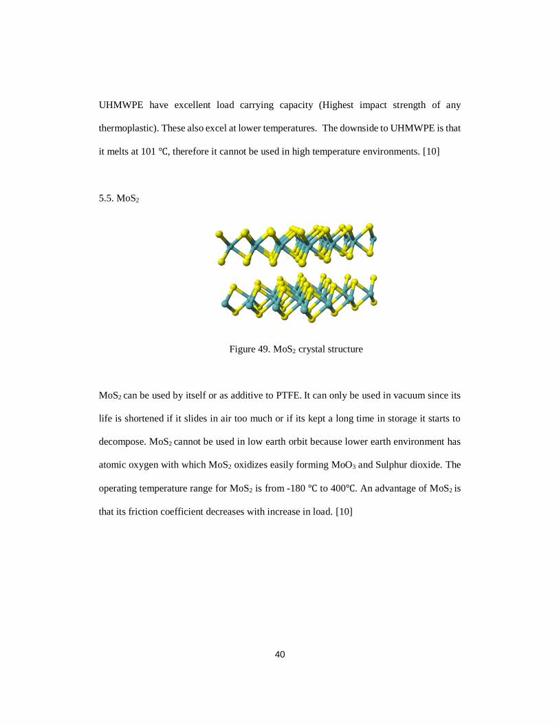
5.5. MoS2
Figure 49. MoS2 crystal structure
MoS2 can be used by itself or as additive to PTFE. It can only be used in vacuum since its
life is shortened if it slides in air too much or if its kept a long time in storage it starts to
decompose. MoS2 cannot be used in low earth orbit because lower earth environment has
atomic oxygen with which MoS2 oxidizes easily forming MoO3 and Sulphur dioxide. The
operating temperature range for MoS2 is from -180 ℃ to 400℃. An advantage of MoS2 is
that its friction coefficient decreases with increase in load. [10]
41
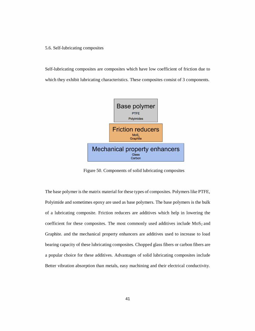
5.6. Self-lubricating composites
Self-lubricating composites are composites which have low coefficient of friction due to
which they exhibit lubricating characteristics. These composites consist of 3 components.
Figure 50. Components of solid lubricating composites
The base polymer is the matrix material for these types of composites. Polymers like PTFE,
Polyimide and sometimes epoxy are used as base polymers. The base polymers is the bulk
of a lubricating composite. Friction reducers are additives which help in lowering the
coefficient for these composites. The most commonly used additives include MoS2 and
Graphite. and the mechanical property enhancers are additives used to increase to load
bearing capacity of these lubricating composites. Chopped glass fibers or carbon fibers are
a popular choice for these additives. Advantages of solid lubricating composites include
Better vibration absorption than metals, easy machining and their electrical conductivity.
42
Some disadvantages of these solid lubricants include low thermal conductivity and
sensitivity to radiation. [10]
For this study we consider Solid lubricating composite which as PTFE as the base polymer
and MoS2 as the additive. MoS2 reduces the friction and also increases the load capacity of
the composite.2 variants of this composite are considered.
1. 15M (which has 15 % MoS2 by weight)
2. 30M ((which has 30 % MoS2 by weight)
Both of these have similar friction characteristics. From room temperature to 200 ℃ we
prefer 30M and for temperature up to 300 ℃ 15M is preferred. [11]
5.7. Mechanism for lubrication
In order to provide best lubrication some sort of shear layer must develop between sliding
surfaces. This shear layer is generated due to weak Van-der-Waals forces between
hexagonal planes. What is desired is a very thin plastically flowing transfer film (less than
2μm). This shear layer thickness depends on the contact area. If the contact area is more, it
will form ridges and cause high localized stress leading to higher friction. [10]

43
5.8. Application methods for Solid lubricants
Solid lubricants may be present in the friction area in forms of either dispersed particles or
surface films. Some of the application techniques are.
Coating (film) - In this technique solid lubricating mixture is ionized or sometimes painted
over the area that is to be lubricated.
Dispersion -Dispersion in the case of composite lubricant is done by adding particles of a
solid lubricant throughout the matrix. Dispersion is also done by introducing solid
lubricating additives in oils or greases.
Powder -Powdered solid lubricant are delivered to the contact area by rubbing these
powders (dry lubrication). This technique produces an uneven layer of lubrication. [12]
The solid lubricating composites can be used on the inner surface of the hinge to provide
lubrication to the hinge. The solid lubricating layer can be around 1 to 2 plies thick. The
lubricating composites can be cured together with the hinge composite material to give a
1-part hinge design.
Figure 51. Solid lubrication application on the hinge
44
5.9. Uses of Hybrid Composite hinge
The new hinge design can be used in deployable solar array in outer space. They can also
be used inside a space rocket to reduce its overall weight, thereby saving cost and energy.
These hinges can also be used on airplanes as hinges for cargo door and other equipment
that rely on a hinge mechanism. For cryogenic application such a hinge can be used in
electron microscopes and various other components that require precision in their motion.

45
CHAPTER 6
Conclusion
It is seen that the only composite hinge has 50 % vertical load carrying capacity of that of
the aluminum hinge. The radial bearing load capacity is also drastically low (≈ 43 % to 47
%) for the composite hinge over the aluminum hinge. The weight of the composite hinge
is 47 % percent lower than the aluminum hinge.
Sandwiching a layer of composite between 2 layers of aluminum drastically improves the
load bearing capacity over the composite only hinge while keeping the weight low. This
hybrid hinge design is a viable alternative to the current generation of aerospace hinges.
Solid lubricants are required for such a hinge design to function optimally. The ideal solid
lubricant would be PTFE + MoS2, Polyimide and MoS2.
46
CHAPTER 7
Future work
The fatigue life of such hinge design has to be determined for better understanding of the
hinge life. Dynamic FEA need to be done to see the stress distribution of the new hinge
design. Progressive damage of the hinge needs to be analyzed. Titanium can be used as an
alternative to aluminum in the hybrid hinge design. An actual physical hinge has to be
manufactured to compare the FEA results and real-world test data. Analyzing its
performance when factors related to temperature are involved. (thermal stresses).

47
Appendix A
Material properties

48
Property Value Units
Density 0.10007 lbs./in3
E 1.0298 x 10⁷ psi
0.33
G 1.0094 x 10⁷ psi
y (Tensile Yield) 40611 psi
u (Tensile Ultimate) 44962 psi
y (Compressive Yield) 40611 psi
u (Compressive Ultimate) 0 psi
3.871 x 10⁷ psi
Table 3. Aluminum alloy properties [13]

49
Property Value Units
Density 0.053468 lbs./in3
E1 1.331 x 10⁷ psi
E2 1.331 x 10⁷ psi
E3 1.305 x 10⁶ psi
12 0.05
23 0.3
13 0.3
G12 2.828 x 10⁶ psi
G23 = G13 4.351 x 10⁵ psi
1 (Tensile)= 2 (Tensile) 1.2 x 10⁵ psi
3 (Tensile) 7251.9 psi
1(Compressive)=2(Compressive) -63672 psi
3 (Compressive) -20305 psi
12 17405 psi
23 = 13 7251.9 psi
thickness 0.25 mm
Table 4. Carbon Epoxy composite properties. [9]
(HMCF - 120 Cure) [9]

50
Appendix B
Load capacity comparisons

51
Figure 52. Horizontal radial bearing load comparison [LUG]
Figure 53. Horizontal radial bearing load comparison [HINGE]

52
Figure 54. Vertical radial load bearing capacity [HINGE]
53
References
[1] Guden hinge catalog (www.guden.com)
[2] www.thomasnet.com/articles/hardware/hinge-manufacturing
[3] www.ladeau.com/hinge-type/custom-hinges/aerospace-hinges/
[4] Monroe hinges – MS20001
[5] Impact and Delamination Failure of Multiscale Carbon Nanotube-Fiber Reinforced Polymer
Composites: A Review (KHAN Shafi Ullah, Kim Jang-Kyo)
[6] Carbon Kevlar hinge by Carbinge
[7] http://www.ansys.stuba.sk/html/elem_55/chapter4/ES4-185.htm
[8] mechanicalc.com – Lug analysis
[9] www.performance-composites.com/carbonfibre/mechanicalproperties_2.asp
[10] Self-lubricating Polymer composites and Polymer transfer film lubrication for space
application – NASA (Robert L. Fusaro)
[11] New Self-Lubricating Polymer Matrix Composites For Journal and Ball Bearing
Applications in Space (SLPMC2) - A. Merstallinger , Z. Simon, G. Nuss , C.E. Paul, M.
Palladino, M. Buttery.
[12] www.engineersedge.com/lubrication/methods_applying_solid_lubricants.htm
[13] MIL -HDBK – 5J
54
Biographical Information
Gaurang Girish Sonpal is a Fall 2016 graduate student of the Mechanical Engineering
Department at the University of Texas at Arlington. He completed his Bachelor of Science
in Mechanical Engineering from the University of Mumbai. His field of interest include
Computer Aided Design, Composite Manufacturing and Design and Finite Element
Analysis. He plans to use his knowledge and expertise for his career growth and develop
better designs and products.