finite element analysis and modifications in plywood ... · department of technology savitribai...
TRANSCRIPT
International Journal of Technical Research and Applications e-ISSN: 2320-8163,
www.ijtra.com Volume 4, Issue 3 (May-June, 2016), PP. 424-435
424 | P a g e
FINITE ELEMENT ANALYSIS AND
MODIFICATIONS IN PLYWOOD STRUCTURE
TO ENHANCE IT'S STRENGTH Ajit Krushnarao Surve
M.Tech+Ph.D. integrated course
Department of Technology
Savitribai Phule Pune university,
Pune
Abstract: This paper explains the plywood. The available
sizes, stresses developed, force distribution of plywood in
different conditions. It outline the mechanics of plywood,
and calculations that relates the in-plane strain and
curvature of a plywood to the forces and bending moments
imposed on it. As plywood are not suitably used where temperatures are
higher, and it is a brittle material so temperature effect and
viscoelastic response is not considered. The analysis is done by
using Ansys software.
Analysis is done by using softwoods, and it is observed
that the plywood are less strong in the radial or bending.
To improve its strength various combinations are done by
using hardwood, softwood and ABS and the result
obtained is 27.5% decreased stress developed in
combination 3. Minimum deformation is observed in
combination2. And minimum strain intensity in
combination2 and 4. By making use of polymers like ABS
it is also possible to change the properties of plywood.
Keywords:Ply, laminates, composite, stress, strain,
deformation.
I. INTRODUCTION
Many of our modern technologies require materials with
unusual combinations of properties that cannot be met by the
conventional metal alloys, ceramics, and polymeric materials.
This is especially true for materials that are needed for
aerospace, underwater, and transportation applications.
Frequently, strong materials are relatively dense; also,
increasing the strength or stiffness generally results in a
decrease in impact strength.
Material property combinations and ranges have been, and are
yet being, extended by the development of composite
materials. Generally speaking, a composite is considered to be
any multiphase material that exhibits a significant proportion
of the properties of both constituent phases such that a better
combination of properties is realized. According to this
principle of combined action, better property combinations are
fashioned by the combination of two or more distinct
materials.
A composite, in the present context, is a multiphase material
that is artificially made, as opposed to one that occurs or forms
naturally.
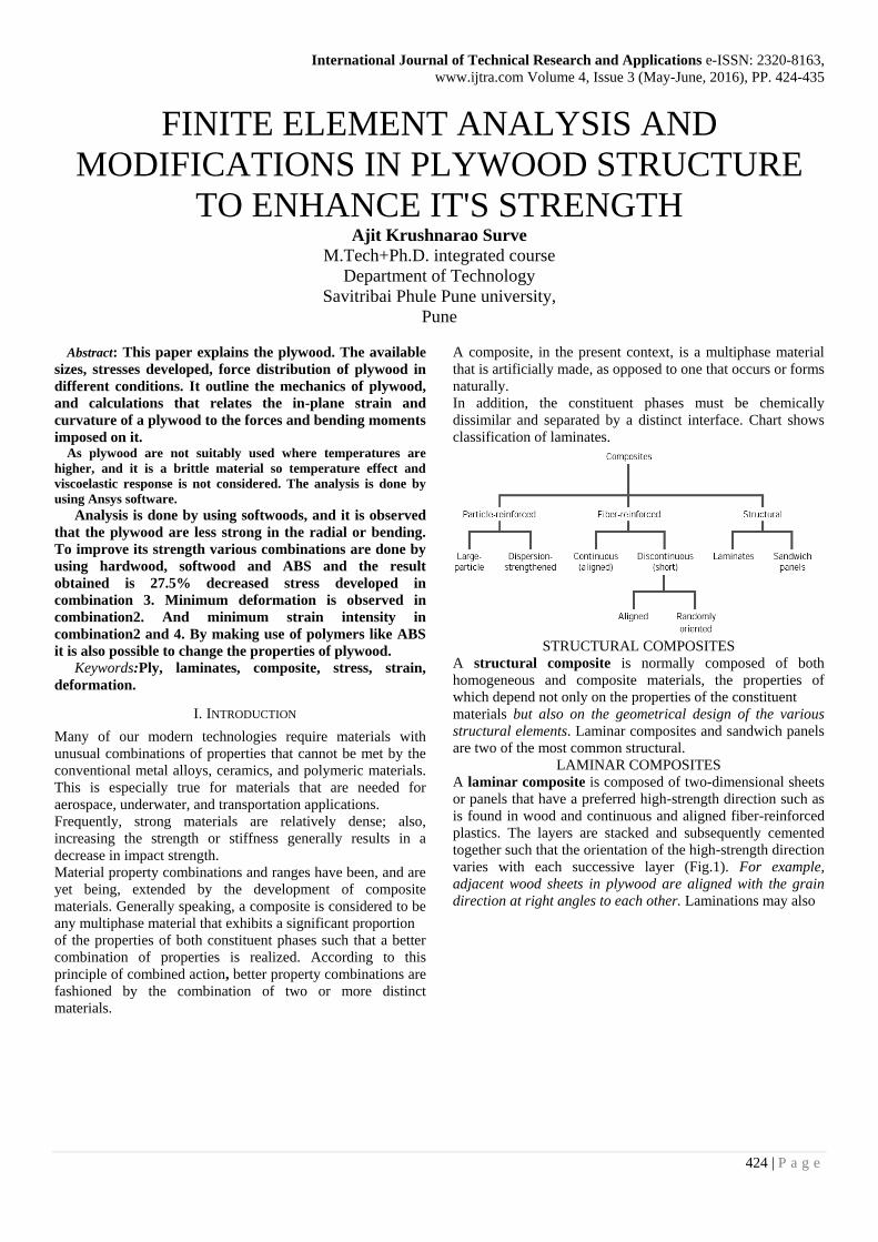
In addition, the constituent phases must be chemically
dissimilar and separated by a distinct interface. Chart shows
classification of laminates.
STRUCTURAL COMPOSITES
A structural composite is normally composed of both
homogeneous and composite materials, the properties of
which depend not only on the properties of the constituent
materials but also on the geometrical design of the various
structural elements. Laminar composites and sandwich panels
are two of the most common structural.
LAMINAR COMPOSITES
A laminar composite is composed of two-dimensional sheets
or panels that have a preferred high-strength direction such as
is found in wood and continuous and aligned fiber-reinforced
plastics. The layers are stacked and subsequently cemented
together such that the orientation of the high-strength direction
varies with each successive layer (Fig.1). For example,
adjacent wood sheets in plywood are aligned with the grain
direction at right angles to each other. Laminations may also
International Journal of Technical Research and Applications e-ISSN: 2320-8163,
www.ijtra.com Volume 4, Issue 3 (May-June, 2016), PP. 424-435
425 | P a g e
be constructed using fabric material such as cotton, paper, or
woven glass fibers embedded in a plastic matrix. Thus a
laminar composite has relatively high strength in a number of
directions in the two-dimensional plane; however, the strength
in any given direction is, of course, lower than it would be if
all the fibers were oriented in that direction.
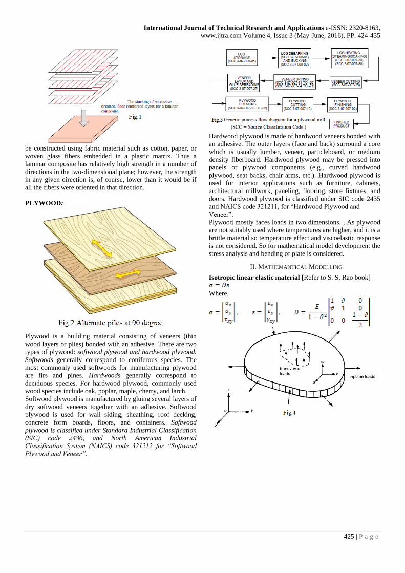
PLYWOOD:
Plywood is a building material consisting of veneers (thin
wood layers or plies) bonded with an adhesive. There are two
types of plywood: softwood plywood and hardwood plywood.
Softwoods generally correspond to coniferous species. The
most commonly used softwoods for manufacturing plywood
are firs and pines. Hardwoods generally correspond to
deciduous species. For hardwood plywood, commonly used
wood species include oak, poplar, maple, cherry, and larch.
Softwood plywood is manufactured by gluing several layers of
dry softwood veneers together with an adhesive. Softwood
plywood is used for wall siding, sheathing, roof decking,
concrete form boards, floors, and containers. Softwood
plywood is classified under Standard Industrial Classification
(SIC) code 2436, and North American Industrial
Classification System (NAICS) code 321212 for “Softwood
Plywood and Veneer”.
Hardwood plywood is made of hardwood veneers bonded with
an adhesive. The outer layers (face and back) surround a core
which is usually lumber, veneer, particleboard, or medium
density fiberboard. Hardwood plywood may be pressed into
panels or plywood components (e.g., curved hardwood
plywood, seat backs, chair arms, etc.). Hardwood plywood is
used for interior applications such as furniture, cabinets,
architectural millwork, paneling, flooring, store fixtures, and
doors. Hardwood plywood is classified under SIC code 2435
and NAICS code 321211, for “Hardwood Plywood and
Veneer”.
Plywood mostly faces loads in two dimensions. , As plywood
are not suitably used where temperatures are higher, and it is a
brittle material so temperature effect and viscoelastic response
is not considered. So for mathematical model development the
stress analysis and bending of plate is considered.
II. MATHEMANTICAL MODELLING
Isotropic linear elastic material [Refer to S. S. Rao book]
Where,
International Journal of Technical Research and Applications e-ISSN: 2320-8163,
www.ijtra.com Volume 4, Issue 3 (May-June, 2016), PP. 424-435
426 | P a g e
Where D=S-1 is the stiffness matrix. Note that the young’s
modulus can be recovered by taking the reciprocal of the 1,1
element of the compliance matrix S, but that the 1,1 position
of the stiffness matrix D contains Poisson effects and is not
equal to E.
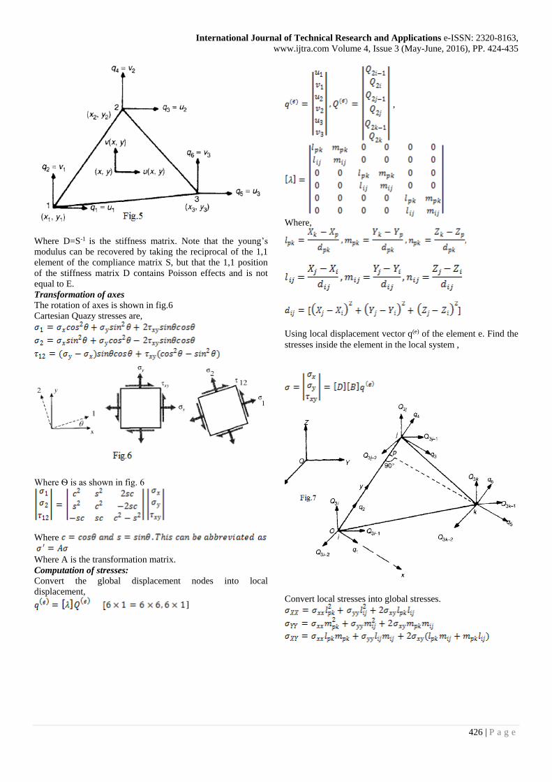
Transformation of axes
The rotation of axes is shown in fig.6
Cartesian Quazy stresses are,
Where Ѳ is as shown in fig. 6
Where
Where A is the transformation matrix.
Computation of stresses:
Convert the global displacement nodes into local
displacement,
]
,
Where,
Using local displacement vector q(e) of the element e. Find the
stresses inside the element in the local system ,
Convert local stresses into global stresses.
International Journal of Technical Research and Applications e-ISSN: 2320-8163,
www.ijtra.com Volume 4, Issue 3 (May-June, 2016), PP. 424-435
427 | P a g e
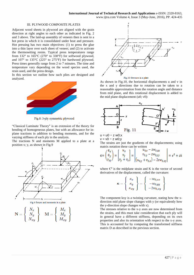
III. PLYWOOD COMPOSITE PLATES
Adjacent wood sheets in plywood are aligned with the grain
direction at right angles to each other as indicated in Fig. 2
and 3 above. The laid-up assembly of veneers then is sent to a
hot press in which it is consolidated under heat and pressure.
Hot pressing has two main objectives: (1) to press the glue
into a thin layer over each sheet of veneer; and (2) to activate
the thermosetting resins. Typical press temperatures range
from 132° to 165°C (270° to 330°F) for softwood plywood,
and 107° to 135°C (225° to 275°F) for hardwood plywood.
Press times generally range from 2 to 7 minutes. The time and
temperature vary depending on the wood species used, the
resin used, and the press design. In this section we outline how such plies are designed and
analyzed.
.
“Classical Laminate Theory" is an extension of the theory for
bending of homogeneous plates, but with an allowance for in-
plane tractions in addition to bending moments, and for the
varying stiffness of each ply in the analysis.
The tractions N and moments M applied to a plate at a
position x; y, as shown in Fig.9
As shown in Fig.10, the horizontal displacements u and v in
the x and y directions due to rotation can be taken to a
reasonable approximation from the rotation angle and distance
from mid plane, and this rotational displacement is added to
the mid plane displacement (u0; v0):
u = u0 − z w0;x v = v0 − z w0;y The strains are just the gradients of the displacements; using
matrix notation these can be written
where Є0 is the midplane strain and K is the vector of second
derivatives of the displacement, called the curvature:
The component kxy is a twisting curvature, stating how the x-
direction mid plane slope changes with y (or equivalently how
the y-direction slope changes with x).
The stresses relative to the x-y axes are now determined from
the strains, and this must take consideration that each ply will
in general have a different stiffness, depending on its own
properties and also its orientation with respect to the x-y axes.
This is accounted for by computing the transformed stiffness
matrix D as described in the previous section.
International Journal of Technical Research and Applications e-ISSN: 2320-8163,
www.ijtra.com Volume 4, Issue 3 (May-June, 2016), PP. 424-435
428 | P a g e
Recall that the ply stiffness as given, are those along the wood
and transverse directions of that particular ply. The properties
of each ply must be transformed to a common x-y axes,
chosen arbitrarily for the entire laminate. The stresses at any
vertical position are then:
σ =Dε = Dε° + zDk where here D is the transformed stiffness of the ply at the
position at which the stresses are being computed.
Each of these ply stresses must add to balance the traction per
unit width N:
where σk is the stress in the kth ply and zk is the distance from
the laminate midplane to the bottom of the kth ply. Using
above Eqn. to write the stresses in terms of the mid-plane
strains and curvatures:
The curvature k and mid plane strain ε0
are constant
throughout z, and the transformed stiffness D does not change
within a given ply. Removing these quantities from within the
integrals:
After evaluating the integrals, this expression can be written in
the compact form:
where A is an \extensional stiffness matrix" defined as:
and B is a \coupling stiffness matrix" defined as:
When the plate is pulled, the more compliant plies above the
mid plane will tend to stretch more than the stiffer plies below
the mid plane. The top half of the plywood stretches more than
the bottom half, so it takes on a concave-downward curvature.
Similarly, the moment resultants per unit width must be
balanced by the moments contributed by the internal stresses:
where D is a bending stiffness matrix" defined as:
The complete set of relations between applied forces and
moments, and the resulting mid plane strains and curvatures,
can be summarized as a single matrix equation:
The A/B/B/D matrix in brackets is the plywood stiffness
matrix, and its inverse will be the plywood compliance matrix.
The presence of nonzero elements in the coupling matrix B
indicates that the application of an in-plane traction will lead
to a curvature or warping of the ply, or that an applied bending
moment will also generate an extensional strain. These effects
are usually undesirable. However, they can be avoided by
making the laminate symmetric about the mid plane, can
reveal. (In some cases, this extension-curvature coupling can
be used as an interesting design feature.
The above relations provide a straightforward (although
tedious, unless a computer is used) means of determining
stresses and displacements in plywood subjected to in-plane
traction or bending loads:
1. For each material type in the stacking sequence, obtain by
measurement or micromechanical estimation the four
independent anisotropic parameters appearing in: (E1, E2,
V12, and G12).
2. Transform the compliance matrix for each ply from the
ply's principal material directions to some convenient
reference axes that will be used for the laminate as a whole.
3. Invert the transformed compliance matrix to obtain the
transformed (relative to x-y axes) stiffness matrix D.
4. Add each ply's contribution to the A, B and D matrices
5. Input the prescribed tractions N and bending moments M,
and form the system equations. 6. Solve the resulting system for the unknown values of in-
plane strain ε° and curvature k.
7. To determine the ply stresses for each ply in the laminate in
terms of ε0, k and z. These will be the stresses relative to the
x-y axes.
8. To transform the x-y stresses back to the principal material
axes (parallel and transverse to the ply).
9. If desired, the individual ply stresses can be used in a
suitable failure criterion to assess the likelihood of that ply
failing. The Tsai-Hill criterion is popularly used for this
purpose:

International Journal of Technical Research and Applications e-ISSN: 2320-8163,
www.ijtra.com Volume 4, Issue 3 (May-June, 2016), PP. 424-435
429 | P a g e
Here σ1 and σ2 are the ply tensile strengths parallel to and
along the fiber direction, and τ12 is the intra ply strength.
This criterion predicts failure whenever the left-hand-side of
the above equation equals or exceeds unity.
IV. CONCLUSION
-As we observe the ansys result the plywood has good strength
in tension and compression.
- It also stronger [less than in tension and compression] when
the load applied is in transverse direction.
- It is not having so much strength in bending (deformation ).
- The results are shown in table.
Property
Longitudinal Trans.
Radial
Tensile Comp.
Deform mm 0-0.057 0-0.057 0-0.87 102
Strain 0.0002 0.0002 0.0028 0.0611
Stress N/mm2 1.23 1.23 12.11 364
V. FINITE ELEMENT ANALYSIS
Geometry and longitudinal force
Deformation
Elastic Strain rate
Stress intensity
International Journal of Technical Research and Applications e-ISSN: 2320-8163,
www.ijtra.com Volume 4, Issue 3 (May-June, 2016), PP. 424-435
430 | P a g e
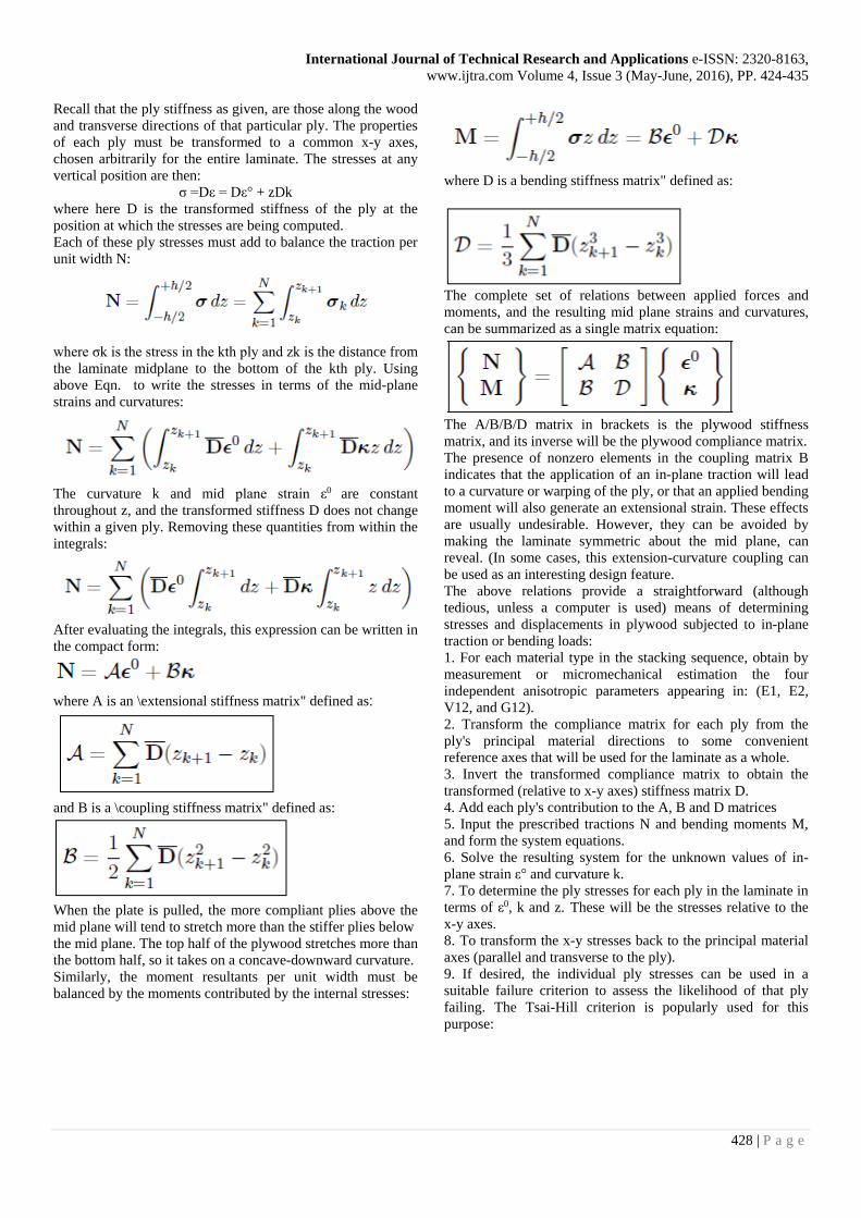
Transverse load
Deformation
Elastic Strain Rate
Stress intensity
Compression Load
Total Deformation
International Journal of Technical Research and Applications e-ISSN: 2320-8163,
www.ijtra.com Volume 4, Issue 3 (May-June, 2016), PP. 424-435
431 | P a g e
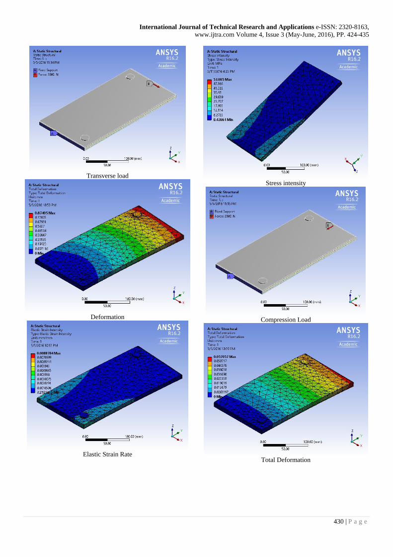
Elastic Strain intensity
Stress intensity
Z direction load [not so much strength 200N]
Total deformation
Elastic strain intensity
Stress intensity
International Journal of Technical Research and Applications e-ISSN: 2320-8163,
www.ijtra.com Volume 4, Issue 3 (May-June, 2016), PP. 424-435
432 | P a g e
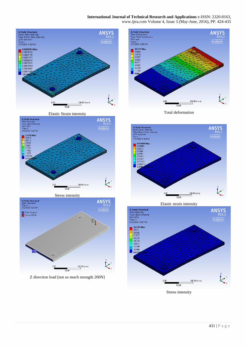
VI. MODIFICATIONS
Here in this paper some modifications by combining the
different woods layer like hardwood, softwood, ABS
polymers are analyzed and the strength and other calculations
are made on the same basis. Total six combinations are used.
There combinations shows different properties and this
becomes the basis for future research. By combining the
different layers of different wood and polymers material it is
possible to obtained plywood equally stronger in all directions
i.e. equally stronger in bending also.
The various combinations used are shown in fig. below
Combination 1
Combination 2
Combination 3
Combination 4
Combination 5
Combination6
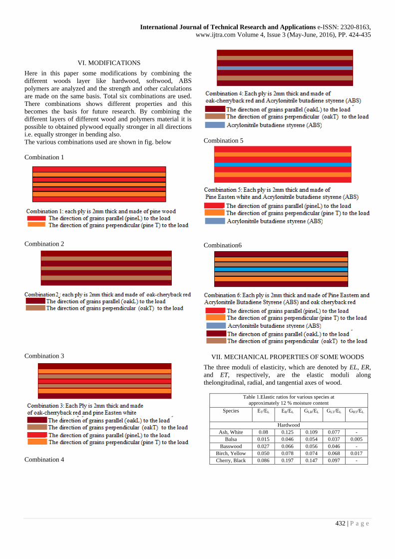
VII. MECHANICAL PROPERTIES OF SOME WOODS
The three moduli of elasticity, which are denoted by EL, ER,
and ET, respectively, are the elastic moduli along
thelongitudinal, radial, and tangential axes of wood.
Table 1.Elastic ratios for various species at
approximately 12 % moisture content
Species ET/EL ER/EL GLR/EL GLT/EL GRT/EL
Hardwood
Ash, White 0.08 0.125 0.109 0.077 -
Balsa 0.015 0.046 0.054 0.037 0.005
Basswood 0.027 0.066 0.056 0.046 -
Birch, Yellow 0.050 0.078 0.074 0.068 0.017
Cherry, Black 0.086 0.197 0.147 0.097 -

International Journal of Technical Research and Applications e-ISSN: 2320-8163,
www.ijtra.com Volume 4, Issue 3 (May-June, 2016), PP. 424-435
433 | P a g e
Cottonwood,
Eastern
0.047 0.083 0.076 0.052 -
Mahogany,
African
0.050 0.111 0.088 0.059 0.021
Mahogany,
honduss
0.064 0.107 0.066 0.086 0.028
Maple,sugar 0.065 0.132 0.111 0.063 -
Maple, red 0.067 0.140 0.133 0.074 -
Oak, red 0.082 0.154 0.089 0.081 -
Oak, White 0.072 0.163 0.086 - -
Sweet gum 0.050 0.115 0.089 0.061 0.021
Walnut, Black 0.056 0.106 0.085 0.062 0.021
Yellow- poplar 0.043 0.092 0.075 0.069 0.011
Softwood
Baldcypress 0.039 0.084 0.063 0.054 0.007
Cedar, Northern
white
0.081 0.183 0.210 0.187 0.015
Cedar, western
red
0.055 0.081 0.087 0.086 0.005
Douglass-fir 0.050 0.068 0.064 0.078 0.007
Fir, subalpine 0.039 0.102 0.070 0.058 0.006
Hemilock,
western
0.031 0.058 0.038 0.032 0.003
Larch western 0.065 0.079 0.063 0.069 0.007
P
I
n
e
Loblolly 0.078 0.113 0.082 0.081 0.013
Lodgepole 0.068 0.102 0.049 0.046 0.005
Longleaf 0.056 0.102 0.071 0.060 0.012
Pond 0.041 0.071 0.050 0.045 0.009
Pondersa 0.083 0.122 0.138 0.115 0.017
Red 0.044 0.088 0.096 0.081 0.011
Slash 0.045 0.074 0.055 0.063 0.010
Sugar 0.087 0.131 0.124 0.113 0.019
Western
White
0.078 0.052 0.048 0.005
Redwood 0.089 0.087 0.036 0.077 0.011
Sprue,sitka 0.043 0.078 0.064 0.061 0.003
Sprue,Engelman
n
0.059 0.128 0.124 0.120 0.010
These moduli are usually obtained from compression tests;
however, data for ER and ET are not extensive. Average
values of ER and ET for samples from a few species are
presented in Table1 as ratios with EL;
The elastic ratios, as well as the elastic constants themselves,
vary within and between species and with moisture content
and specific gravity.
The modulus of elasticity determined from bending, EL, rather
than from an axial test, may be the only modulus of elasticity
available for a species.
As tabulated, EL includes an effect of shear deflection; EL
from bending can be increased by 10% to remove this effect
approximately.
Acrylonitrile butadiene styrene (ABS) Properties
Table 3: Acrylonitrile butadiene styrene (ABS) Properties
Physical Properties Metric
Density 1.04g/cc
Melt flow 18-23g/10min
Mechanical Properties
Hardness Rockwell 102-112
Tensile strength, Yeild 42.5-44.8 MPa
Elongation at break 23-25%
Flexural Modulus 2.25-2.28 GPa
Flexural Yeild Strength 60.6-73.1 MPa
Izod impact, Notched 2.46-2.94 J/cm
Poisson’s ratio 0.35
Poisson’s Ratio
When a member is loaded axially, the deformation
perpendicular to the direction of the load is proportional to the
deformation parallel to the direction of the load. The ratio of
the transverse to axial strain is called Poisson’s ratio. The
Poisson’s ratios are denoted by μLR, μRL, μLT, μTL, μRT , μTR.
The first letter of the subscript refers to direction of applied
stress and the second letter to direction of lateral deformation.
For example, μLR is the Poisson’s ratio for deformation along
the radial axis caused by stress along the longitudinal axis.
Average values of Poisson’s ratios for samples of a few
species are given in Table 2. Poisson’s ratios vary within and
between species and are affected by moisture content and
specific gravity.
International Journal of Technical Research and Applications e-ISSN: 2320-8163,
www.ijtra.com Volume 4, Issue 3 (May-June, 2016), PP. 424-435
434 | P a g e
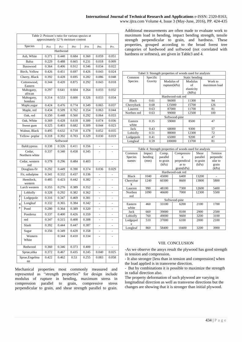
Mechanical properties most commonly measured and
represented as “strength properties” for design include
modulus of rupture in bending, maximum stress in
compression parallel to grain, compressive stress
perpendicular to grain, and shear strength parallel to grain.
Additional measurements are often made to evaluate work to
maximum load in bending, impact bending strength, tensile
strength perpendicular to grain, and hardness. These
properties, grouped according to the broad forest tree
categories of hardwood and softwood (not correlated with
hardness or softness), are given in Table3 and 4.
Tabel 3: Strength properties of woods used for analysis
Common
Species
Specific
Gravity
Static bending
Modulus of
rupture(kPa)
Modulus
of
elasticity
(MPa)
Work to
maximum load
Hardwood-oak red
Black 0.61 96000 11300 94
Cherrybark 0.68 125000 15700 126
Laurren 0.63 87000 11700 81
Northen red 0.63 99000 12500 100
Softwood-pine
Eastern
white
0.35 59000 8500 47
Jack 0.43 68000 9300 57
Lobiolly 0.51 88000 12300 72
Lodgepole 0.41 65000 9200 47
Longleaf 0.59 100000 13700 81
Table 4: Strength properties of woods used for analysis
Common
Species
names
Impact
bending
(mm)
Comp.
parallel
to grain
(kPa)
Compressio
n
perpendicul
ar to
grain(kPa)
Shear
parallel
to grain
(kPa)
Tension
perpendic
ular to
grain
(kPa)
Hardwood-oak red
Black 1040 45000 6400 13200 -
Cherrybar
k
1240 60300 8600 13800 5800
Laurren 990 48100 7300 12600 5400
Northen
red
1090 46600 7000 12300 5500
Softwood-pine
Eastern
white
460 33100 6200 2100 1700
Jack 660 39000 8100 2900 2500
Lobiolly 760 49000 9600 3200 3100
Lodgepol
e
510 37000 6100 2000 2100
Longleaf 860 58400 10400 3200 3900
VIII. CONCLUSION
-As we observe the ansys result the plywood has good strength
in tension and compression.
- It also stronger [less than in tension and compression] when
the load applied is in transverse direction.
- But by combinations it is possible to maximize the strength
in radial direction also.
The property deformation of such plywood are varying in
longitudinal direction as well as transverse directions but the
changes are showing that it is stronger than initial plywood.
Table 2: Poisson’s ratio for various species at
approximately 12 % moisture content
Species μLR μLT μRT μTR μRL μTL
Hardwood
Ash, White 0.371 0.440 0.684 0.360 0.059 0.051
Balsa 0.229 0.488 0.665 0.231 0.018 0.009
Basswood 0.364 0.406 0.912 0.346 0.034 0.022
Birch, Yellow 0.426 0.451 0.697 0.426 0.043 0.024
Cherry, Black 0.392 0.428 0.695 0.282 0.086 0.048
Cottonwood,
Eastern
0.344 0.420 0.875 0.292 0.043 0.018
Mahogany,
african
0.297 0.641 0.604 0.264 0.033 0.032
Mahogany,
honduss
0.314 0.533 0.600 0.326 0.033 0.034
Maple,sugar 0.424 0.476 0.774 0.349 0.065 0.037
Maple, red 0.434 0.509 0.762 0.354 0.063 0.044
Oak, red 0.350 0.448 0.560 0.292 0.064 0.033
Oak, White 0.369 0.428 0.618 0.300 0.074 0.036
Sweet gum 0.325 0.403 0.682 0.309 0.044 0.023
Walnut, Black 0.495 0.632 0.718 0.378 0.052 0.035
Yellow- poplar 0.318 0.392 0.703 0.329 0.030 0.019
Softwood
Baldcypress 0.338 0.326 0.411 0.356 - -
Cedar,
Northern white
0.337 0.340 0.458 0.345 - -
Cedar, western
red
0.378 0.296 0.484 0.403 - -
Douglass-fir 0.292 0.449 0.390 0.374 0.036 0.029
Fir, subalpine 0.341 0.332 0.437 0.336 - -
Hemilock,
western
0.485 0.423 0.442 0.382 - -
Larch western 0.355 0.276 0.389 0.352 - -
P
I
n
e
Loblolly 0.328 0.292 0.382 0.362 - -
Lodgepole 0.316 0.347 0.469 0.381 - -
Longleaf 0.332 0.365 0.384 0.342 - -
Pond 0.280 0.364 0.389 0.320 - -
Pondersa 0.337 0.400 0.426 0.359 - -
red 0.347 0.315 0.408 0.308 - -
Slash 0.392 0.444 0.447 0.387 - -
Sugar 0.356 0.349 0.428 0.358 - -
Western
White
0.329 0.344 0.410 0.334 - -
Redwood 0.360 0.346 0.373 0.400 - -
Sprue,sitka 0.372 0.467 0.435 0.245 0.040 0.025
Sprue,Engelma
nn
0.422 0.462 0.53 0.255 0.083 0.058
International Journal of Technical Research and Applications e-ISSN: 2320-8163,
www.ijtra.com Volume 4, Issue 3 (May-June, 2016), PP. 424-435
435 | P a g e
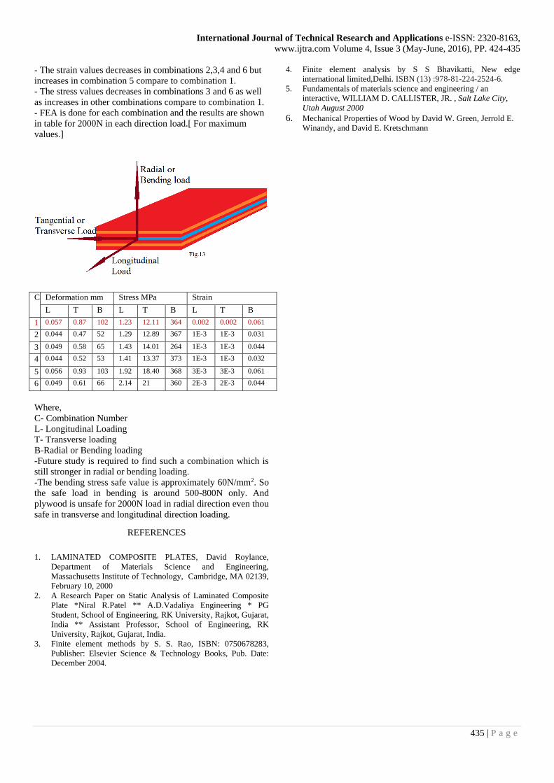
- The strain values decreases in combinations 2,3,4 and 6 but
increases in combination 5 compare to combination 1.
- The stress values decreases in combinations 3 and 6 as well
as increases in other combinations compare to combination 1.
- FEA is done for each combination and the results are shown
in table for 2000N in each direction load.[ For maximum
values.]
C Deformation mm Stress MPa Strain
L T B L T B L T B
1 0.057 0.87 102 1.23 12.11 364 0.002 0.002 0.061
2 0.044 0.47 52 1.29 12.89 367 1E-3 1E-3 0.031
3 0.049 0.58 65 1.43 14.01 264 1E-3 1E-3 0.044
4 0.044 0.52 53 1.41 13.37 373 1E-3 1E-3 0.032
5 0.056 0.93 103 1.92 18.40 368 3E-3 3E-3 0.061
6 0.049 0.61 66 2.14 21 360 2E-3 2E-3 0.044
Where,
C- Combination Number
L- Longitudinal Loading
T- Transverse loading
B-Radial or Bending loading
-Future study is required to find such a combination which is
still stronger in radial or bending loading.
-The bending stress safe value is approximately 60N/mm2. So
the safe load in bending is around 500-800N only. And
plywood is unsafe for 2000N load in radial direction even thou
safe in transverse and longitudinal direction loading.
REFERENCES
1. LAMINATED COMPOSITE PLATES, David Roylance,
Department of Materials Science and Engineering,
Massachusetts Institute of Technology, Cambridge, MA 02139,
February 10, 2000
2. A Research Paper on Static Analysis of Laminated Composite
Plate *Niral R.Patel ** A.D.Vadaliya Engineering * PG
Student, School of Engineering, RK University, Rajkot, Gujarat,
India ** Assistant Professor, School of Engineering, RK
University, Rajkot, Gujarat, India.
3. Finite element methods by S. S. Rao, ISBN: 0750678283,
Publisher: Elsevier Science & Technology Books, Pub. Date:
December 2004.
4. Finite element analysis by S S Bhavikatti, New edge
international limited,Delhi. ISBN (13) :978-81-224-2524-6.
5. Fundamentals of materials science and engineering / an
interactive, WILLIAM D. CALLISTER, JR. , Salt Lake City,
Utah August 2000
6. Mechanical Properties of Wood by David W. Green, Jerrold E.
Winandy, and David E. Kretschmann